Article

Theoretical Investigation of Laser Induced Magnetization Reversal by Spin Orbit Coupling and Stimulated Raman Scattering

1
Wuhan National Laboratory of Optoelectronics, Huazhong University of Science and Technology, Wuhan 430074, China
2
School of Physics, Huazhong University of Science and Technology, Wuhan 430074, China
3
Guangdong Provincial Key Laboratory of Optical Fiber Sensing and Communications, Institute of Photonics Technology, Jinan University, Guangzhou 510632, China
*
Author to whom correspondence should be addressed.
Appl. Sci. 2019, 9(1), 102; https://doi.org/10.3390/app9010102
Submission received: 19 November 2018 / Revised: 12 December 2018 / Accepted: 21 December 2018 / Published: 29 December 2018
(This article belongs to the Special Issue Ultrafast Electronic Dynamics in Solids)

Abstract

:
We theoretically study the mechanism of the all-optical magnetic switching by combining the Rashba effect and stimulated Raman scattering. In hydrogenlike systems, we show that the Rashba effect splits the energy band and stimulated Raman scattering transits the electrons between the lambda three-level system and controls the spin states to reverse the orientation of magnetization. The dynamics of electrons are described with the Lindblad equation in a few hundreds of femtoseconds. We further investigate the influence of laser intensity and wavelength on the probability of spin-flip in a ferromagnetic material, CoPt.

1. Introduction

It has been reported that circularly polarized femtosecond laser pulses can deterministically switch the orientations of magnetization of certain materials [1,2,3,4,5], including rare-earth transition metal alloys [3,6], CoPt [7,8,9], and their multilayer films [10]. However, the fundamental mechanism remains an open question that impedes the further development of study.
All-optical magnetic switching is phenomenologically explained as a combination of effects derived from the inverse Faraday effect (IFE) [11,12,13] and heat described as the two-temperature model [5,14,15,16,17,18], and all can be treated as effective magnetic fields [5,19,20,21]. However, in a microscopic scale, the origin of IFE and the interaction between laser pulses and magnetic materials is only studied in few publications [12,22]. The early attempt carried out by Pitaevskii et al. [11] in 1961 theoretically predicted the existence of IFE in the frame of a thermodynamic potential. The first experimental observation of IFE was published by Ziel et al. [13] in 1965; Pershan et al. [12] explained the origin of the IFE from the view of quantum mechanics, and gave a quantitative expression for the IFE field. However, the derived effective Hamiltonian and standard magnetic field by Pershan, M ( t ) E ( t ) E ( t ) , is not applicable for sub-picosecond and high-intensity laser scenarios, because the research assumed that the variation of the pulse amplitude is negligible during the magnetization switching process. The two-temperature model is proposed to reconcile the contradiction between the time scale and the magnitude of magnetic field [4]. However, heat alone can only demagnetize the magnetic materials [23], if the material is not an anti-ferromagnetic system.
To suitably fit the study for the process of ultra-fast magnetization reversal, IFE derived by stimulated Raman scattering (SRS) was proposed by Popova [24,25] who deduced the effective magnetic field from the second order of the time-dependent Hamiltonian. In her study, SRS stimulates the electron transition and changes the spin state, which is helicity dependent, in magnetic materials. Instead of the Schrodinger picture, we are going to use the density matrix formalism to describe the transitions which allows introducing the decay rate easily.
In recent studies, the Rashba effect [26,27,28] is engineered to be coupled to laser schemes [29,30,31]. The circularly polarized laser-induced Rashba effect produces an effective magnetic field on CoPt [31]. The effective field is opposite to the magnetization direction; however, the magnitude of the effective field is helicity dependent. For left-handed circularly polarized light and magnetization along the z direction that is normal to the sample, the effective field is much greater than the right-handed circularly polarized laser-induced effective field. During the oscillation of electronic dipole transition, the angular moment should obey conservation law, which forbids the transitions with spin flips. The effective field induced by the Rashba effect contributes to the angular moment injection of the three-level system during the transitions, besides the function of splitting the energy band.
According to Pitaevskii and Pershan et al., the inverse Faraday field consists of two processes: (1) the light is directly interacted with magnetic materials, and (2) this interaction produces a quasi-stationary relaxed state, which leads to the birth of magnetization in the sample. In this paper, SRS is discussed both qualitatively and quantitatively in the transient process, which corresponds to the direct interaction of light with materials. The Rashba effect, the sub-picosecond time scale process [32], is treated as the builder of the quasi-stationary state.
Here, we utilize the ab initio theorem with the two effects mentioned above to get the insight of transient process of magnetization switching on a femtosecond scale. The Rashba effect-induced fine structure is spin-dependent, so the sub-bands are exclusive for spin-up or spin-down. More importantly, the effective field supplies a tunnel to flip spins at an excited state. The laser drives electrons to oscillate between the two sub-bands and virtual excited state, and all of the three constitute a Λ three-level system. In these transitions, spin-up may transform to spin-down, and all the oscillation will be described in the Rabi model [33,34,35]. We specify the simulation on CoPt which is commonly investigated by previous studies [8,12,31]. The final probability of spin state is controllable with the intensity and wavelength of laser.

2. Interaction of Light and Medium

In consideration of the result of Qaiumzadeh et al. [31], the laser-induced Rashba effect is treated as an effective magnetic field. As shown in Figure 1, the sub-bands |1> and |3> split by the effective field and the virtual state |2> constitute the Λ three-level system. For the femtosecond laser, the monochromaticity is relatively poor. ωe and ωr correspond to different wavelengths included in the femtosecond laser. Δer) is the mismatch of the energy of the incident photos, ωer), and the energy gap between |1> and |2>, ω12 (|3> and |2>, ω23).
The dynamics of electrons shown in Figure 1 describe the process of SRS [36,37]. Electrons are originally steady at state |1> with spin-up. After the incidence of laser, electrons are stimulated to virtual state |2>. Meanwhile, the incident laser, including the frequency ωr that is approximate to ω23, stimulates electrons radiating to state |3>. Therefore, SRS transfers electrons between different energy bands; the Rashba effect-induced effective field gives states |1> and |3> with specific spin states. More importantly, the effective field does not only maintain the quasi-stationary state, but also break the transition forbidden for spin-flip.
We are going to use the Rabi model to describe the process of SRS instead of the form of nonlinear polarization, because the distribution of laser in the spatial domain is neglected. However, in the framework of the Rabi model without decay, electrons will remain on the virtual state, because of the sudden stop of the laser. Therefore, we investigate the transition in a three-level system by the Lindblad equation, which is easy to describe how a density operator evolves in an open system with decay. Diagonal elements of the density matrix represent the probability of electrons occupying the state:
ρ ˙ = i [ H , ρ ] + L ( ρ )
L ( ρ ) = C ρ C 1 2 ( C C ρ + ρ C C )
where the first term of the right-hand side of Equation (1) is the Liouville-von Neumann equation [33], describing the unitary evolution of the density operator; ρ is the density matrix of the three-level system and ρ ˙ represents the elements of density matrix take a derivative of time; H is a 3 × 3 matrix expression of Hamiltonian and the elements of the matrix are written as ωnm; C describes the decay of electrons to ground state; C* is the transpose of C. We choose specific time-dependent phases to simplify the diagonal elements of H, and define the elements as:
W 11 = 0 ,   W 22 = Δ 1 = Δ e , W 33 = Δ 2 = ( Δ e Δ r )
Δ e = ω 12 ω e ,   Δ r = ω 23 ω r
where ω12 and ω23 are the angular frequencies corresponding to the difference of energy of states |2>, |1> and |2>, |3>, respectively; ωe and ωr are the angular frequencies of incident femtosecond laser.
The off-diagonal elements of interaction Hamiltonian is considered as electric dipole transitions, dnm, for which an atomic dipole moment is affected by a classical electric field, Enm(t). Enm(t) is the envelope of a Gaussian laser. Parameters followed by the subscript of nm represent that they are related with the interaction between states |n> and |m>.
W n m = 1 2 d n m E n m ( t ) , ( n m )
Therefore, the complete Hamiltonian is:
H = [ 0 W 12 0 W 12 Δ 1 W 23 0 W 23 Δ 2 ]
For L ( ρ ) , C is determined by decay rates γ1 and γ3:
C = [ 0 γ 1 0 0 0 0 0 γ 3 0 ]
In the simulation, the time scale of incident laser is about 100 fs, which means the spectrum is extended. According to the uncertainty principle, ∆t∙∆ν ≥ 0.441; for the Gaussian pulse, frequency bandwidth, ∆ν, is at least 4.4 × 10¹⁴ Hz. As shown in Figure 3a, it is possible that ω12 and ω23 are contained in one laser beam. ω12 and ω23 are defined by ω12 = ω0 − Δω, and ω23 = ω0 + Δω, respectively. ω0 represents the energy difference between the initial ground state of material and the virtual state. ∆ω is determined by the strength of the Rashba effect-induced effective field. ∆ω = αR∙p, where αR is the Rashba coefficient and p is the momentum of electrons, which is tunable by adjusting the materials and structure. We choose the frequencies that ω23 = ωr, and ω12 = ωe which is the most sensitive and predigests the computational complexity. The Rashba effect-induced band split, 2∆ω, may variate with the intensity of incident light, but the broad spectrum of femtosecond laser insures the self-adaption, maintaining ω23 = ωr, and ω12 = ωe. The Hamiltonian is evolved to:
H = [ 0 W 12 0 W 12 0 W 23 0 W 23 0 ]
Substituting Equations (7) and (8) into Equations (1) and (2), the evolution of density matrix can be easily observed. The Hermitian Hamiltonian and Lindbladian terms guarantee the density matrix maintaining Hermitian in the duration of the laser interaction.

3. Discussion

3.1. Initial State of Material

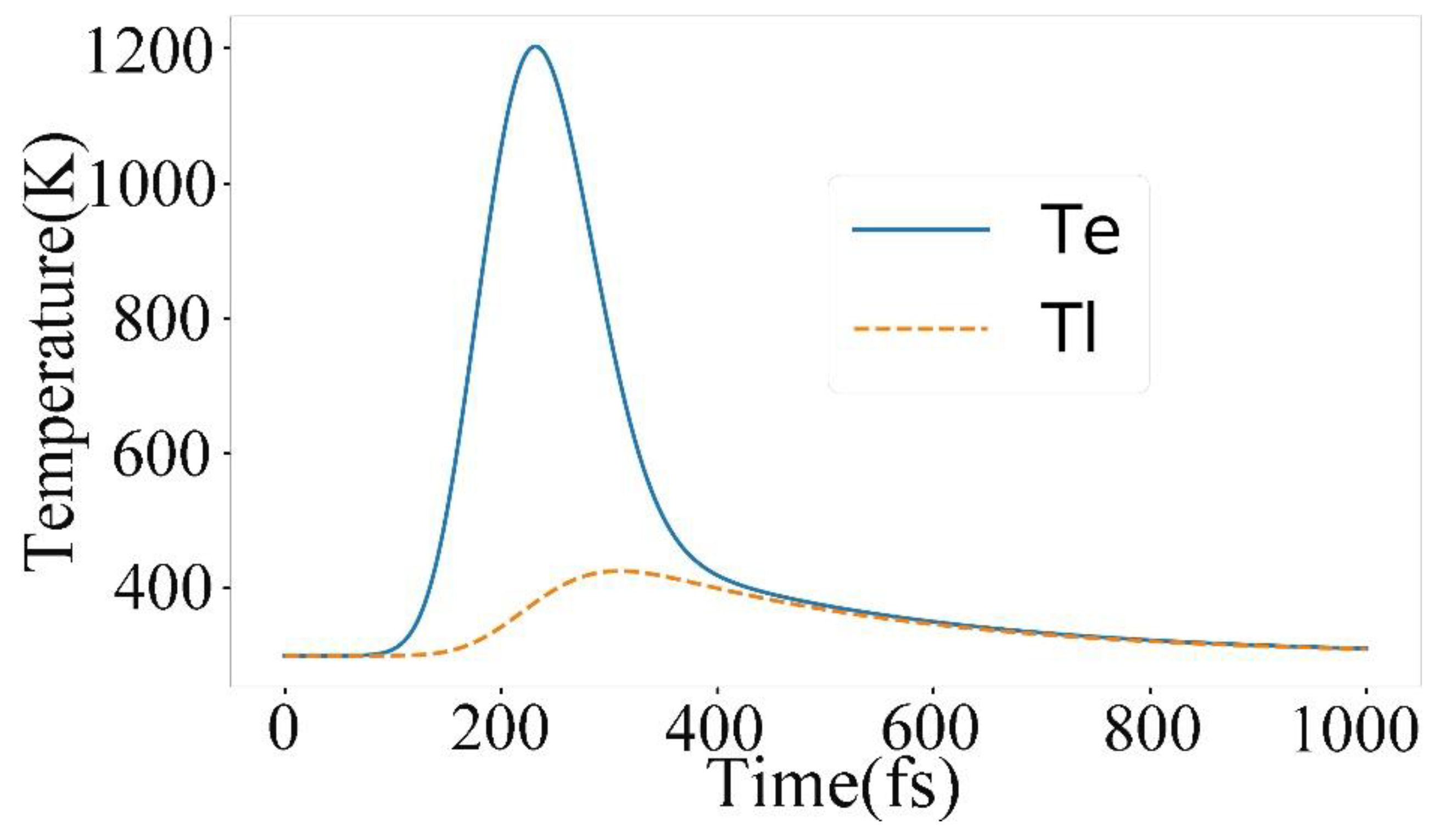
Following the previous researches [7,25,31], we specify our investigation to ferromagnetic material CoPt, on which all-optical switching is dependent on the helicity of polarization. We attribute the helicity dependence to the Rashba effect-induced effective field [31] and the transition rules of SRS [25]. In the experiment, the material is pre-magnetized. However, considering the high intensity of laser, the temperature of electrons reaches the Curie temperature before the dramatic electron oscillations. Here, we briefly introduce the two-temperature model to demonstrate the ultrafast soar of electron temperature. The process is described by the two coupled equations:
C e ( T e ) d T e d t = G · ( T e T p ) + P , d T p d t = G · ( T e T p ) / C p ( T p T 0 ) · s
where Te and Tp represent the electron and phonon temperature, respectively; Ce(Te) and Cp are the specific heats of the electron and phonon, respectively; Ce(Te) is proportional to Te, and Ce(Te) = C0∙Te; C0 is the coefficient that does not relate to temperature; P is the pump power of the pulse, which follows the Gaussian distribution in intensity vs time. Additionally, we ignore the penetration loss for less than 20-nm-thickness thin films; G and s are the electron-phonon coupling constant and the heat sink coupling constant, respectively. The main parameters of the two-temperature model and the corresponding typical values are listed in our previous work [17].
The multilayer CoPt structure was firstly discovered the phenomenon of all-optical switching, but the Curie temperature, Tc, is not mentioned in the original paper [7]. We find that the Curie temperature is varied from the thickness of Co and Pt layers, but the Curie temperature is generally less than 500 K. [38,39] Figure 2 shows the temperature fluctuation of electrons and lattice in 1 ps. When electrons near the Curie temperature before the intensity of laser reaches highest, the magnetization disappears. Therefore, even though the magnetic material is pre-magnetized in the experiment, we initialize our simulation system with the balance state of spin-up and spin-down.

3.2. Spin State Transition

ω0 is the intrinsic property of materials, but Δω is determined by the intensity of laser. By controlling Δω and the difference between the center frequencies of femtosecond laser ω and ω0, the distributions of final spin states are various. Here, Figure 3a shows a specific relation between ω, ω0 and Δω (ω12 = ω0 − Δω, ω23 = ω0 + Δω) and the electric field of laser, E12 = 2E23, where ω12 equals to the center frequency of the incident laser.
We ignore the difference of electric dipoles d12 = d23, because Δω is much less than ω0; decay rates γ1 = γ3 = 0.01, which can be neglected during the interaction between laser and materials. The pick intensity of electric field, E12, is ~109 V/m. The pulse width τ of the simulation in Figure 3 is 100 fs and the peak of the laser is reached at 2τ. In this model, the effective field induced by the Rashba effect breaks the transition forbidden with spin-flip, but the influence to the transition between |2> and |3> is not discussed. Instead, the magnitude of electric filed directly determines the speed of the transition.
Figure 3a shows the relationship between the incident laser and the energy gap of ω12 and ω23. The full line describes the distribution of frequency versus the electric field. The intersections of vertical imaginary lines and the profile of the laser are corresponding to the magnitude of electric field for the interaction of laser and material. In Figure 3b, the intensity of electric dipole transition, ω12 and ω23 are 1.4 eV and 0.7 eV, respectively. ρ1 and ρ3 are the probabilities of spin state at |1> and |3>, respectively; initially, ρ1 = ρ3 = 0.5. The results in Figure 3b can be qualitatively explained by the fact that more electrons at state |1> are excited by higher intensity of laser than those at state |3>, which maintains the population density at state |2>, while more electrons stimulated radiate to state |3>. The separate dynamics of the three states are ignored, but the process of magnetization is shown in Figure 3b, because the difference of the probability of spin-up and -down, Δρ = ρ3 − ρ1, reflects the magnetization of the sample. The final state of Δρ is steady at about 0.11, which indicates a determinate all-optical magnetic switching.
Because of the equality of γ1 and γ3 which are assigned previously, electrons decay to |1> and |3> with the same speed. Δρ keeps constant after about 300 fs when there are electrons that remain staying at the virtual state. However, the decay rate should be considered with the surrounding areas. The direction of the magnetization of material after the interaction of laser affects the tendency to decaying to spin-up or -down. Δρ should be greater than the result displayed in Figure 3b, but we still assume that γ1 equals to γ3 in the following simulations, which does not significantly affect the final probability Δρ.
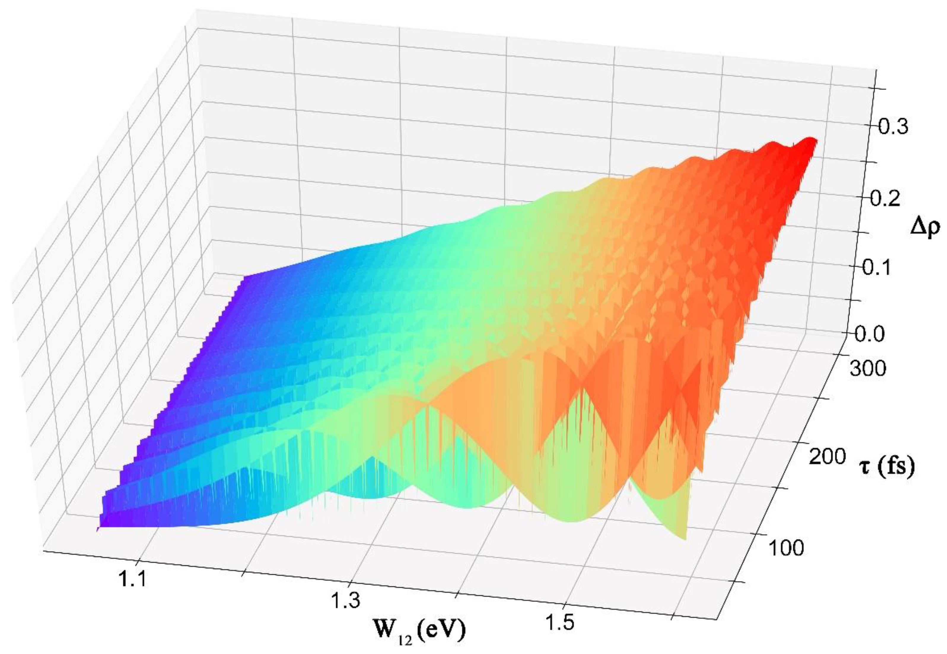
We further investigate the effect of the variation of the pulse width and the intensity of laser to the final state of Δρ. In Figure 4, the intensity variation is reflected by ω12. The summation of ω12 and ω23 is constant to be 2.1 eV and ω12 varies from 1.05 to 1.6 eV. τ represents the pulse width of laser; the peak of the intensity of laser is reached at 2τ; the simulation time is set as 6τ. Δρ oscillates when ω12 increases, but the tendency of Δρ is increased. The amplitude of the oscillation decreases with the augment of the pulse width τ. Δρ is approximately proportional to ω12 when the pulse width increases to 300 fs. Because of the short pulse width, the oscillation of electrons suddenly stops before the oscillation reaches equilibrium, whereas the envelop of the electric field with a long pulse width changes gradually so that electron oscillation can follow the variation of electric field. Therefore, the determination of the final spin state resulting from the duration of laser is not important when the pulse width is greater than 100 fs.
The wavelength and intensity-related spin-flip supplies a channel to control the final state of the magnetization. It is obvious that the spin states keep balanced when E12 = E23 in Figure 4. When the sum of ω12 and ω23 is still 2.1 eV and ω12 decreases from 1.05 to 0.5 eV, Δρ will be odd symmetric to the flat of W12 = 1.05 in Figure 4. Therefore, by adjusting the distribution of the relative intensities that correspond to ω12 and ω23, the area where the magnetization is reversed can be smaller than that of the incident laser.

4. Conclusions

All-optical magnetic switching is a sophisticated process that merges multi-effects influencing the spin state at different time scales and dominating at different times. We ignore the influence of magnetism and only investigate the first 6τ, when the interaction of laser and material preponderates. The heat breaks the initial state to the demagnetization and energy barrier for spin-flip. The Rashba effect splits the ground state to fine energy bands which are spin-dependent and keeps the angular moment conservation. SRS is treated as an adiabatic passage that transits electrons between spin-up and -down and the intermedia virtual excited state.
We utilize the framework of Rabi oscillation with the Lindblad equation to describe the process of electron transition and the dynamic of magnetization. The magnetization reflected by the difference of spin-up and -down is manipulated by the intensity of laser corresponding to a specific wavelength and a definite magnetization reversal is realized. After the pulse width is greater than 100 fs, the final state of the magnetization is approximately proportional to ω12.
The model may be rough, but it reflects the dynamic of magnetization reversal. The discovery of the wavelength and intensity-sensitive magnetization reversal supplies a possible way to reduce the area of recorded size with the far field laser in the future. The next step of our investigation will focus on the combination of the process of SRS and traditional magnetism, because traditional magnetism supplies a complete theory to describe the dynamic of magnetization in a longer time scale.

Author Contributions

Y.Z. performed the simulation; H.W. edited and audited the content; C.X. acquired funding. All authors read and approved the manuscript.

Funding

This work is funded by the National Nature Science Foundation of China (NSFC) (grant No.: 61432007).

Conflicts of Interest

The authors declare no conflict of interest.

References

  1. Kirilyuk, A.; Kimel, A.V.; Rasing, T. Ultrafast optical manipulation of magnetic order. Rew. Mod. Phys. 2010, 82, 2731. [Google Scholar] [CrossRef]
  2. Stupakiewicz, A.; Szerenos, K.; Afanasiev, D.; Kirilyuk, A.; Kimel, A. Ultrafast nonthermal photo-magnetic recording in a transparent medium. Nature 2017, 542, 71–74. [Google Scholar] [CrossRef] [PubMed] [Green Version]
  3. Stanciu, C.; Hansteen, F.; Kimel, A.; Kirilyuk, A.; Tsukamoto, A.; Itoh, A.; Rasing, T. All-optical magnetic recording with circularly polarized light. Phys. Rev. Lett. 2007, 99, 047601. [Google Scholar] [CrossRef] [PubMed]
  4. Vahaplar, K.; Kalashnikova, A.; Kimel, A.; Hinzke, D.; Nowak, U.; Chantrell, R.; Tsukamoto, A.; Itoh, A.; Kirilyuk, A.; Rasing, T. Ultrafast path for optical magnetization reversal via a strongly nonequilibrium state. Phys. Rev. Lett. 2009, 103, 117201. [Google Scholar] [CrossRef] [PubMed]
  5. Ostler, T.; Barker, J.; Evans, R.; Chantrell, R.; Atxitia, U.; Chubykalo-Fesenko, O.; El Moussaoui, S.; Le Guyader, L.; Mengotti, E.; Heyderman, L. Ultrafast heating as a sufficient stimulus for magnetization reversal in a ferrimagnet. Nat. Commun. 2012, 3, 666. [Google Scholar] [CrossRef] [PubMed] [Green Version]
  6. Alebrand, S.; Gottwald, M.; Hehn, M.; Steil, D.; Cinchetti, M.; Lacour, D.; Fullerton, E.E.; Aeschlimann, M.; Mangin, S. Light-induced magnetization reversal of high-anisotropy TbCo alloy films. Appl. Phys. A 2012, 101, 162408. [Google Scholar] [CrossRef] [Green Version]
  7. Lambert, C.-H.; Mangin, S.; Varaprasad, B.C.S.; Takahashi, Y.; Hehn, M.; Cinchetti, M.; Malinowski, G.; Hono, K.; Fainman, Y.; Aeschlimann, M. All-optical control of ferromagnetic thin films and nanostructures. Science 2014, 345, 1337–1340. [Google Scholar] [CrossRef] [PubMed] [Green Version]
  8. Cornelissen, T.; Córdoba, R.; Koopmans, B. Microscopic model for all optical switching in ferromagnets. Appl. Phys. Lett. 2016, 108, 142405. [Google Scholar] [CrossRef] [Green Version]
  9. Choi, G.-M.; Schleife, A.; Cahill, D.G. Optical-helicity-driven magnetization dynamics in metallic ferromagnets. Nat. Commun. 2017, 8, 15085. [Google Scholar] [CrossRef] [Green Version]
  10. Mangin, S.; Gottwald, M.; Lambert, C.; Steil, D.; Uhlíř, V.; Pang, L.; Hehn, M.; Alebrand, S.; Cinchetti, M.; Malinowski, G. Engineered materials for all-optical helicity-dependent magnetic switching. Nat. Mater. 2014, 13, 286–292. [Google Scholar] [CrossRef]
  11. Pitaevskii, L. Electric forces in a transparent dispersive medium. Sov. Phys. JETP 1961, 12, 1008–1013. [Google Scholar]
  12. Pershan, P.; Van der Ziel, J.; Malmstrom, L. Theoretical discussion of the inverse Faraday effect, Raman scattering, and related phenomena. Phys. Rev. 1966, 143, 574. [Google Scholar] [CrossRef]
  13. Van der Ziel, J.; Pershan, P.; Malmstrom, L. Optically-induced magnetization resulting from the inverse Faraday effect. Phys. Rev. Lett. 1965, 15, 190. [Google Scholar] [CrossRef]
  14. Jiang, L.; Tsai, H.-L. Improved two-temperature model and its application in ultrashort laser heating of metal films. J. Heat Transf. 2005, 127, 1167–1173. [Google Scholar] [CrossRef]
  15. Kimel, A.V.; Kirilyuk, A.; Rasing, T. Femtosecond opto-magnetism: Ultrafast laser manipulation of magnetic materials. Laser Photon. Rev. 2007, 1, 275–287. [Google Scholar] [CrossRef]
  16. Huang, T.; Wang, H.; Zou, Y.; Cheng, W.; Xie, C. Explorations on size limit of L10-FePt nanoparticles for practical magnetic storage. AIP Adv. 2016, 6, 115302. [Google Scholar] [CrossRef] [Green Version]
  17. Huang, T.; Wang, H.; Cheng, W.; Zou, Y.; Xie, C. Critical switching fluence of L10-FePt nanoparticles with practical size to ultrafast all-optical polarization switching. EPL 2017, 118, 67006. [Google Scholar] [CrossRef]
  18. Steil, D.; Alebrand, S.; Hassdenteufel, A.; Cinchetti, M.; Aeschlimann, M. All-optical magnetization recording by tailoring optical excitation parameters. Phys. Rev. B 2011, 84, 224408. [Google Scholar] [CrossRef]
  19. Evans, R.F.; Fan, W.J.; Chureemart, P.; Ostler, T.A.; Ellis, M.O.; Chantrell, R.W. Atomistic spin model simulations of magnetic nanomaterials. J. Phys. Condens. Matter 2014, 26, 103202. [Google Scholar] [CrossRef] [Green Version]
  20. Evans, R.F.; Ostler, T.A.; Chantrell, R.W.; Radu, I.; Rasing, T. Ultrafast thermally induced magnetic switching in synthetic ferrimagnets. Appl. Phys. Lett. 2014, 104, 082410. [Google Scholar] [CrossRef] [Green Version]
  21. Radu, I.; Vahaplar, K.; Stamm, C.; Kachel, T.; Pontius, N.; Dürr, H.; Ostler, T.; Barker, J.; Evans, R.; Chantrell, R. Transient ferromagnetic-like state mediating ultrafast reversal of antiferromagnetically coupled spins. Nature 2011, 472, 205–208. [Google Scholar] [CrossRef] [PubMed]
  22. Battiato, M.; Barbalinardo, G.; Oppeneer, P.M. Quantum theory of the inverse Faraday effect. Phys. Rev. B 2014, 89, 014413. [Google Scholar] [CrossRef]
  23. Atxitia, U.; Chubykalo-Fesenko, O.; Kazantseva, N.; Hinzke, D.; Nowak, U.; Chantrell, R.W. Micromagnetic modeling of laser-induced magnetization dynamics using the Landau-Lifshitz-Bloch equation. Appl. Phys. A 2007, 91, 232507. [Google Scholar] [CrossRef] [Green Version]
  24. Popova, D. Microscopic description of the inverse Faraday effect at subpicosecond time scales. Available online: https://core.ac.uk/download/pdf/36614088.pdf (accessed on 20 December 2018).
  25. Popova, D.; Bringer, A.; Blügel, S. Theoretical investigation of the inverse Faraday effect via a stimulated Raman scattering process. Phys. Rev. B 2012, 85, 094419. [Google Scholar] [CrossRef]
  26. Manchon, A.; Koo, H.C.; Nitta, J.; Frolov, S.; Duine, R. New perspectives for Rashba spin-orbit coupling. Nat. Mater. 2015, 14, 871–882. [Google Scholar] [CrossRef] [PubMed]
  27. Krupin, O.; Bihlmayer, G.; Starke, K.; Gorovikov, S.; Prieto, J.; Döbrich, K.; Blügel, S.; Kaindl, G. Rashba effect at magnetic metal surfaces. Phys. Rew. B 2005, 71, 201403. [Google Scholar] [CrossRef]
  28. Miron, I.M.; Gaudin, G.; Auffret, S.; Rodmacq, B.; Schuhl, A.; Pizzini, S.; Vogel, J.; Gambardella, P. Current-driven spin torque induced by the Rashba effect in a ferromagnetic metal layer. Nat. Mater. 2010, 9, 230–234. [Google Scholar] [CrossRef] [PubMed] [Green Version]
  29. Chen, X.-J. Fundamental mechanism for all-optical helicity-dependent switching of magnetization. Sci. Rep. 2017, 7, 41294. [Google Scholar] [CrossRef] [PubMed] [Green Version]
  30. Edelstein, V.M. Inverse faraday effect in conducting crystals caused by a broken mirror symmetry. Phys. Rev. Lett. 1998, 80, 5766. [Google Scholar] [CrossRef]
  31. Qaiumzadeh, A.; Titov, M. Theory of light-induced effective magnetic field in Rashba ferromagnets. Phys. Rew. B 2016, 94, 014425. [Google Scholar] [CrossRef]
  32. Etienne, T.; Mosconi, E.; De Angelis, F. Dynamical Origin of the Rashba Effect in Organohalide Lead Perovskites: A Key to Suppressed Carrier Recombination in Perovskite Solar Cells? J. Phys. Chem. Lett. 2016, 7, 1638–1645. [Google Scholar] [CrossRef] [PubMed]
  33. Shore, B.W. Manipulating Quantum Structures Using Laser Pulses; Cambridge University Press: Cambridge, UK, 2011. [Google Scholar]
  34. Batista, A.A. Rabi oscillations in two-level systems beyond the rotating-wave approximation. arXiv, 2015; arXiv:1507.05124. [Google Scholar]
  35. Hughes, S. Breakdown of the area theorem: Carrier-wave Rabi flopping of femtosecond optical pulses. Phys. Rev. Lett. 1998, 81, 3363. [Google Scholar] [CrossRef]
  36. Yang, X.; Wong, C.W. Coupled-mode theory for stimulated Raman scattering in high-Q/Vm silicon photonic band gap defect cavity lasers. Opt. Express 2007, 15, 4763–4780. [Google Scholar] [CrossRef] [PubMed]
  37. Monfared, Y.E.; Ponomarenko, S.A. Non-Gaussian statistics of extreme events in stimulated Raman scattering: The role of coherent memory and source noise. Phys. Rev. A 2017, 96, 043817. [Google Scholar] [CrossRef]
  38. Cai, W.; Muraishi, S.; Shi, J.; Nakamura, Y.; Liu, W.; Yu, R. Curie temperatures of CoPt ultrathin continuous films. Appl. Phys. A 2012, 107, 519–523. [Google Scholar] [CrossRef]
  39. Inaba, N.; Igarashi, S.; Kirino, F.; Fujita, F.; Koike, K.; Kato, H. Magnetic properties of Co/Pt-Pd multilayer thin film media. Phys. Status Solidi C 2007, 4, 4498–4502. [Google Scholar] [CrossRef]
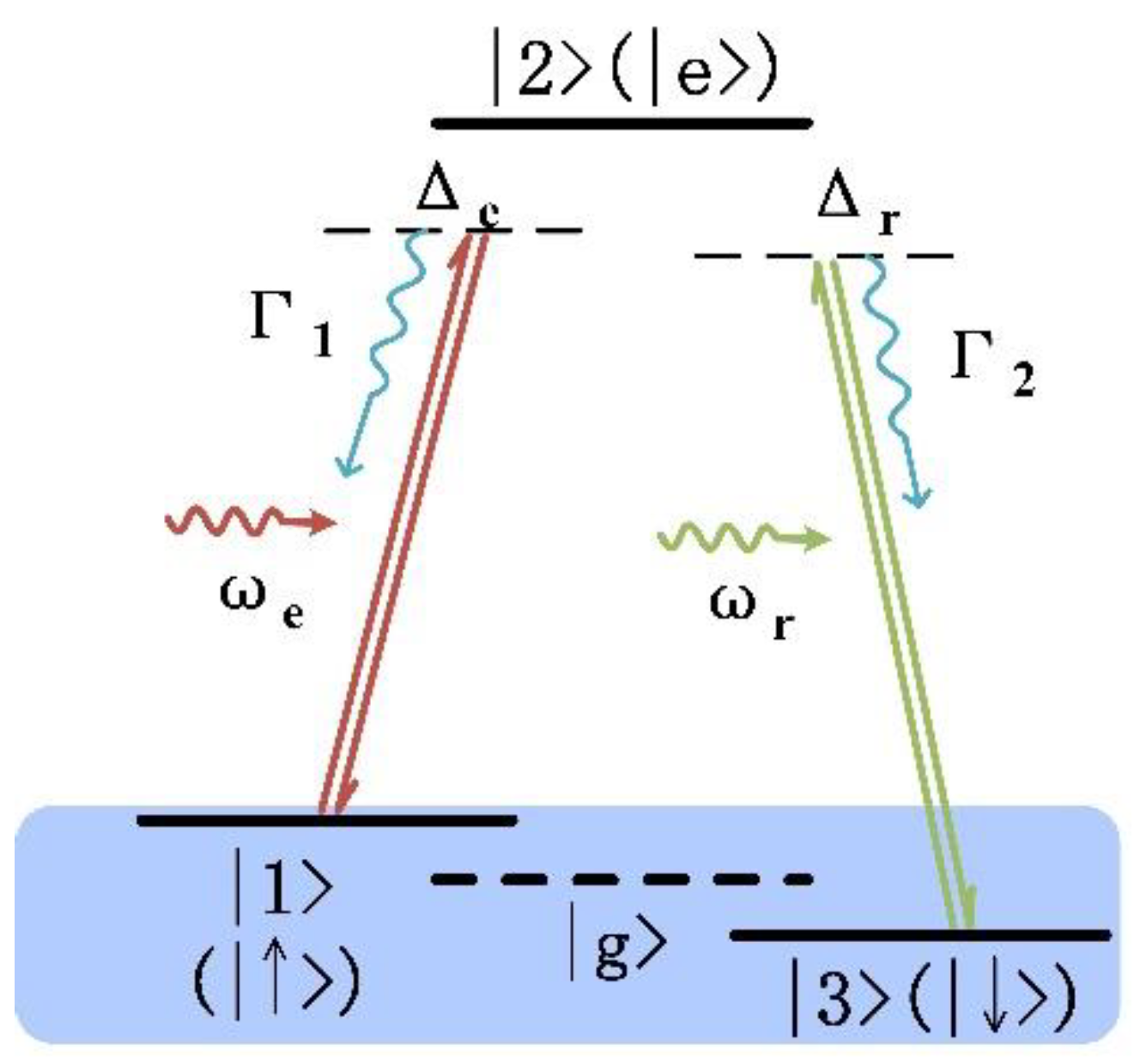
Figure 1. The schematic diagram of a Λ three-level system. The ground state is split into two fine energy bands, caused by the Rashba effect, in the ming blue background. |1> and |3> are spin-up or -down, respectively. |e> is a virtual state in the stimulated Raman scattering process, Γ1 and Γ2 are the decay rates.
Applsci 09 00102 g001
Figure 2. Two-temperature model for electrons and lattice. It can be seen that the temperature of electrons dramatically rises to Tc of 500 K from room temperature of 300K within 150 fs.
Applsci 09 00102 g002
Figure 3. (a) The frequency spectrum of the femtosecond laser compared with the energy gap between |1> and |e> (ω12), |g> and |e> (ω0), |3> and |e> (ω23). The intensity of electronic filed ω12 is twice that of ω23. (b) Dependence of ρ3 − ρ1 on time. ρ3 − ρ1 represents the occupation probability difference between states |1> (spin-up) and |3> (spin-down). The spin determines the orientation of magnetization.
Applsci 09 00102 g003
Figure 4. Δρ, the probability difference of states |3> and |1>, varies with ω12 and pulse width. When the pulse width is less than 100 fs and ω12 increases, Δρ increases with dramatic fluctuation. When the pulse width is larger than 100 fs, ω12 = 1.6, and ω23 = 0.5, Δρ approximately stabilizes at 0.28.
Applsci 09 00102 g004