Effect of Additional Shielding Gas on Welding Seam Formation during Twin Wire DP-MIG High-Speed Welding


Abstract
:1. Introduction
2. Experimental Methods and Materials
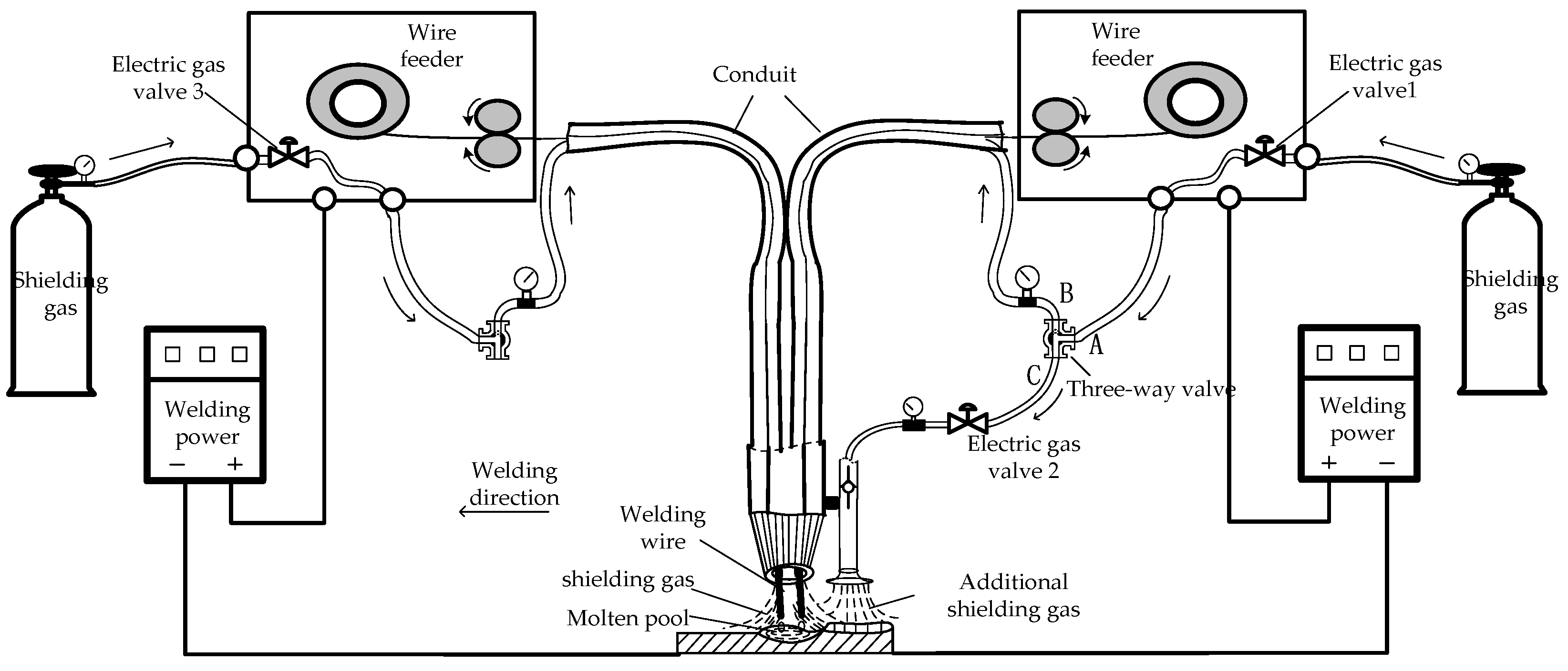
2.1. Experimental Equipment and Methods
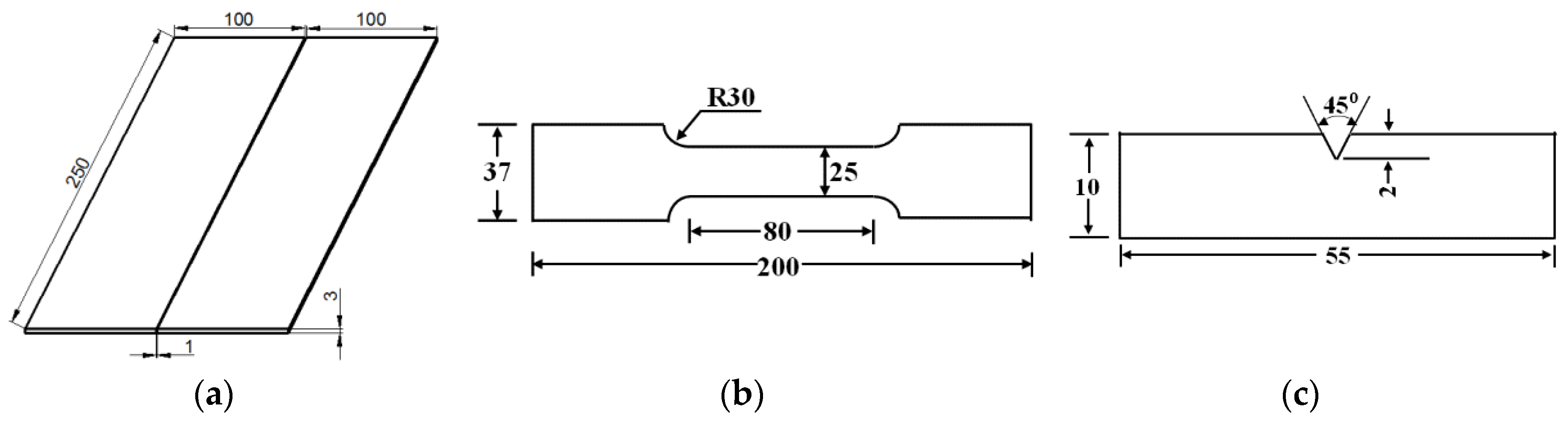
2.2. Experimental Materials and Processing
3. Results
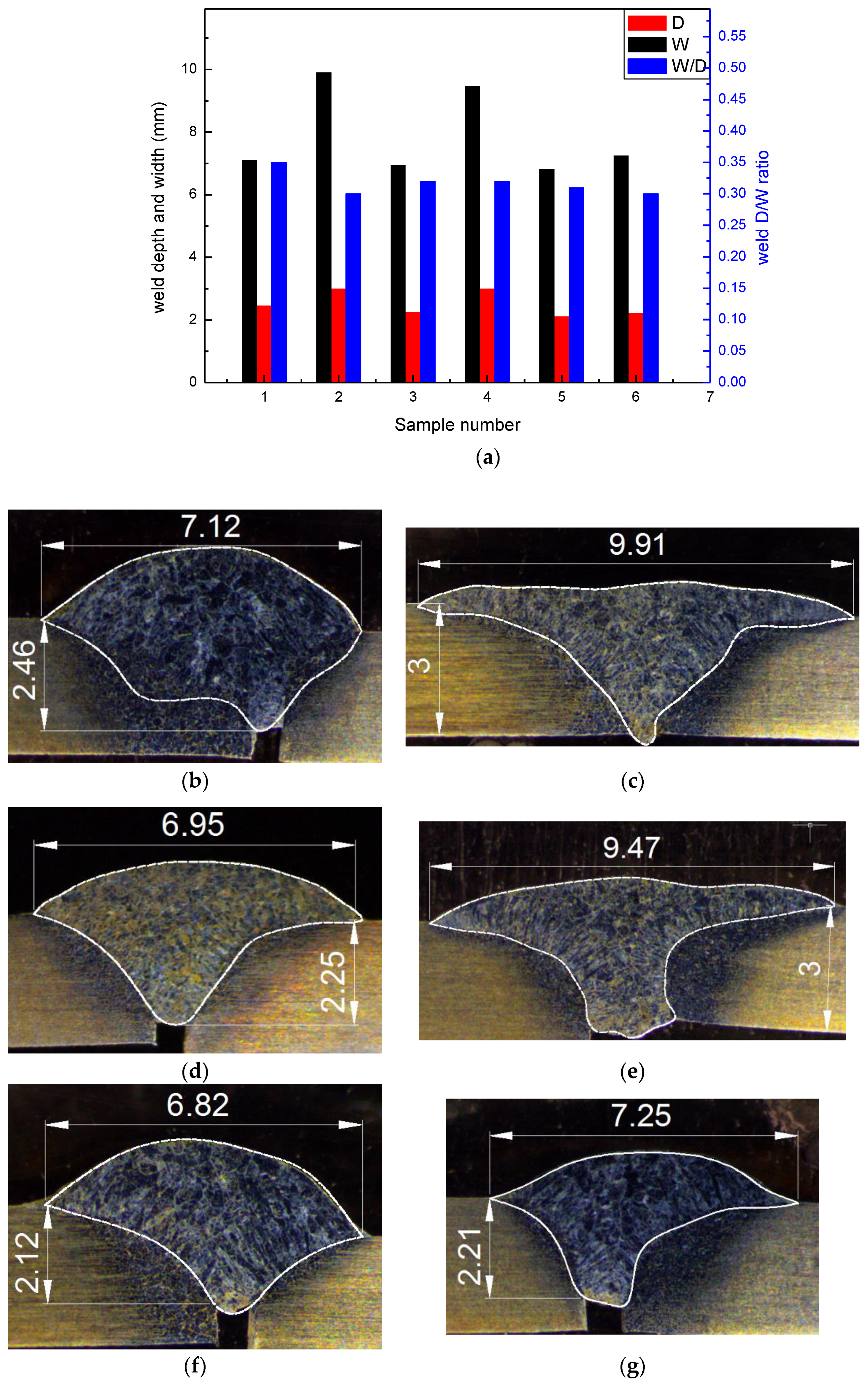
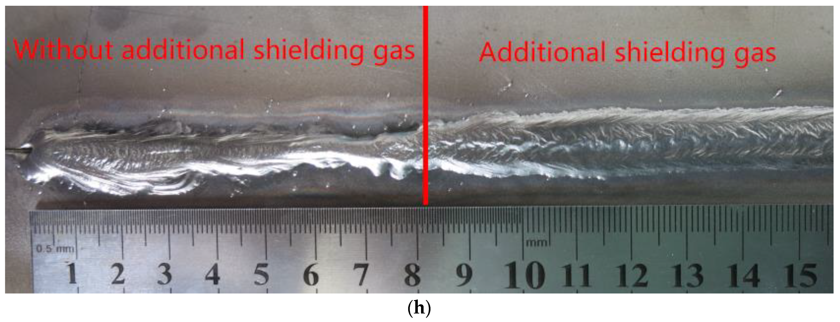
3.1. Formation of the Weld Seam
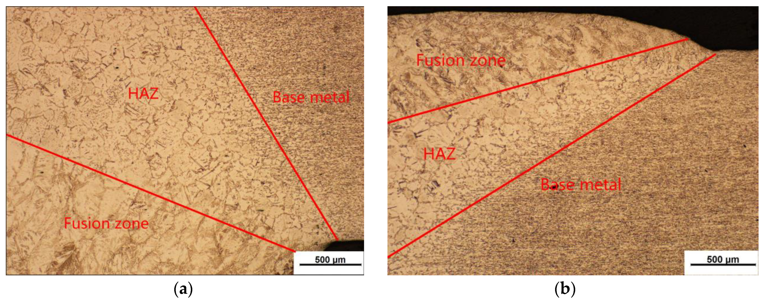
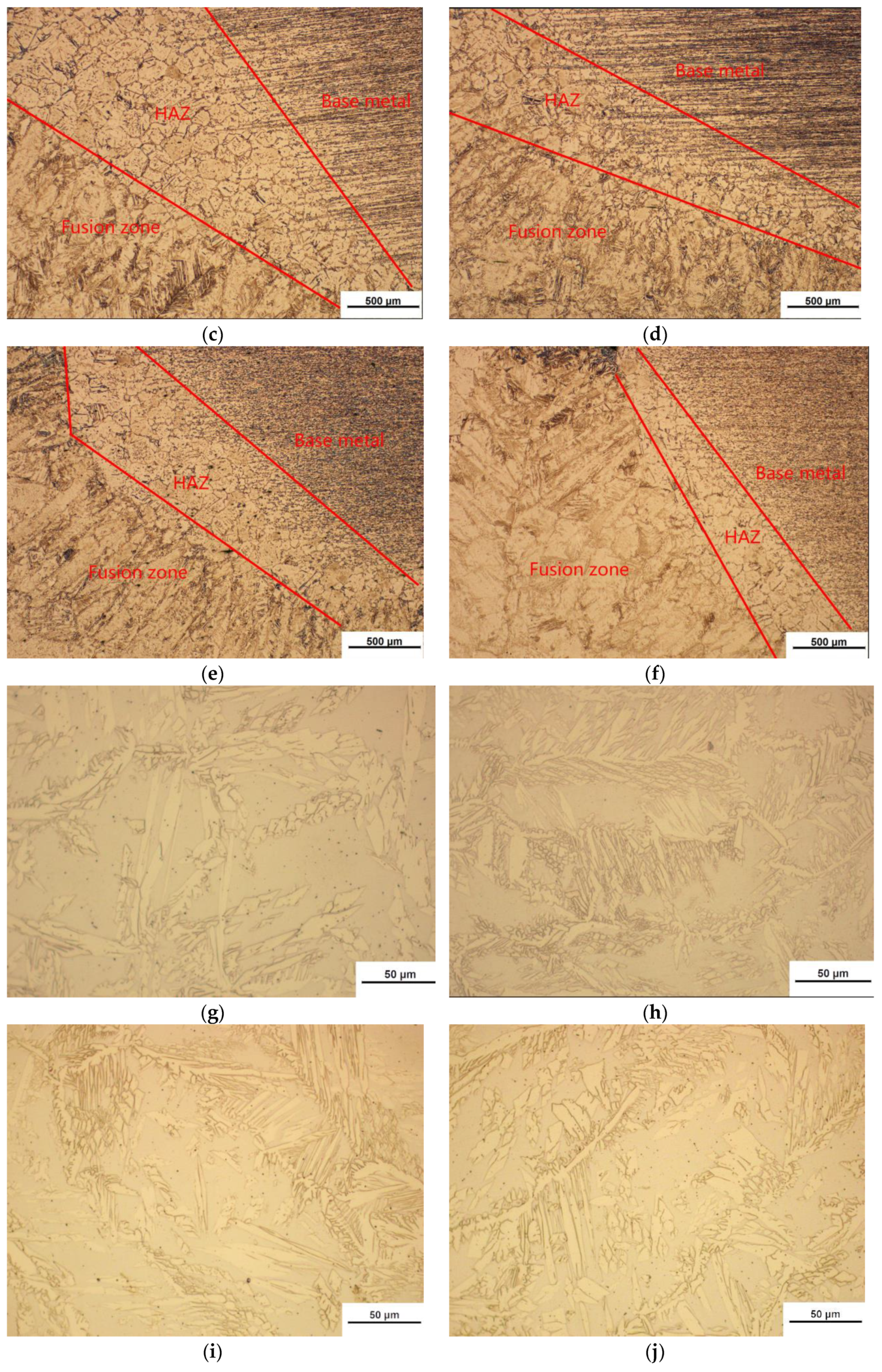
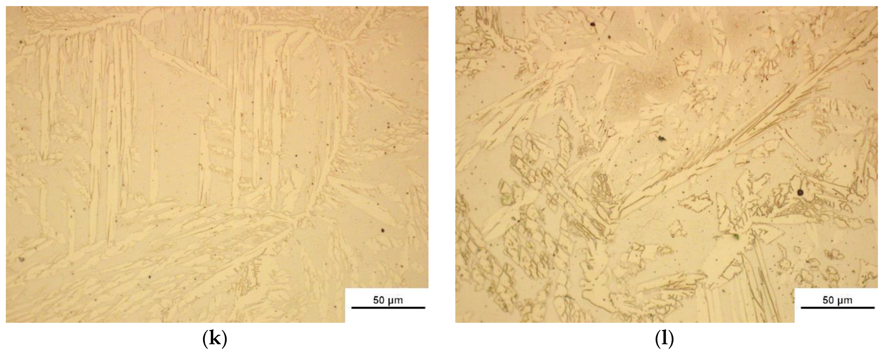
3.2. Results of Metallographic Tests
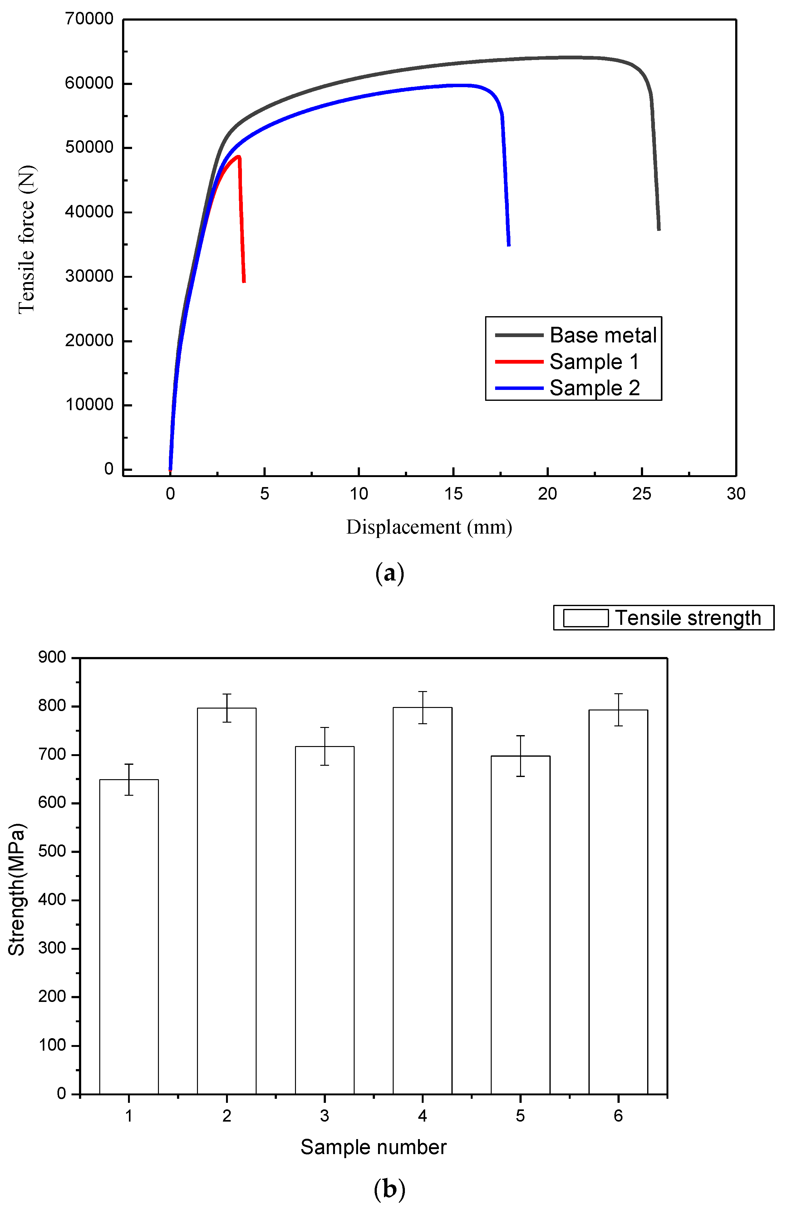
3.3. Mechanical Properties
4. Conclusions
- (1)
- The welding process is more stable; the weld width is more uniform; the unfused defects of the weld can be effectively improved and diminished.
- (2)
- Due to the action of the external gas flow, the fluidity of the molten pool metal is better than that formed without additional shielding gas. The heat-affected zone is smaller than that of the weld seam formed without the additional shielding gas.
- (3)
- The tensile properties of the welded joints are significantly improved. When the welding speed was 1.6, 1.8, and 2.0 m/min, the maximum tensile strength of the joints increased by 19.7%, 8.2% and 11.3%, respectively.
- (4)
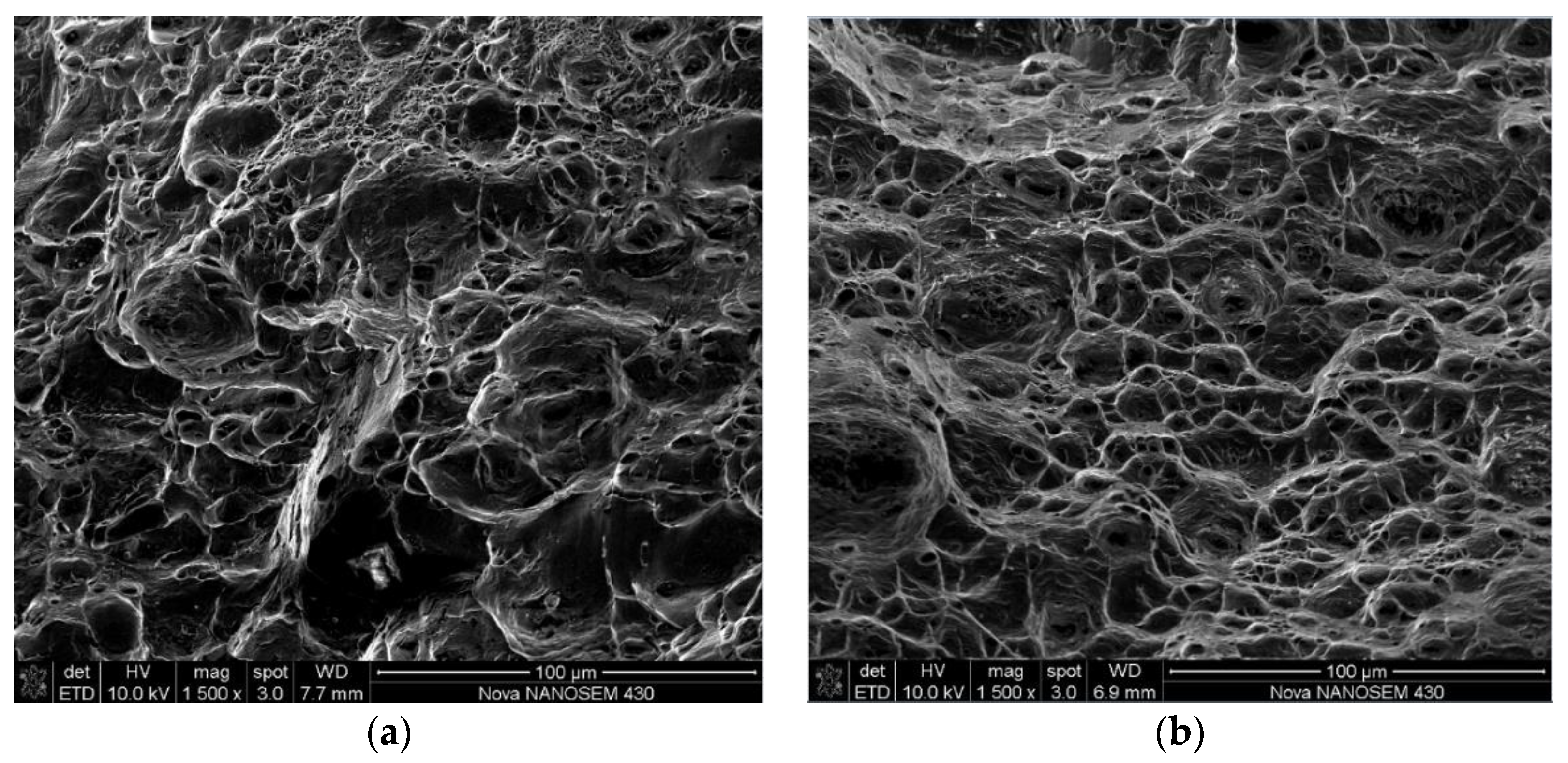
- At the same welding current and welding speed, the absorbed energy of the joint without the additional shielding gas ranges from 12 to 18.2 J (22.2–33.7% of the base metal), while the absorbed energy of the joint with the additional shielding gas ranges from 27 to 30 J (50–55.6% of the base metal), indicating that the joint with additional shielding gas has higher absorbed energy and better toughness.
Author Contributions
Funding
Conflicts of Interest
References
- Chen, Y.; Liu, L.; Zhang, H. Effect of heat input on microstructure and toughness of weld joint of high strength low-alloy steel. J. Shang Hai Jiao Tong Univ. 2015, 49, 306–309. [Google Scholar]
- Moinuddin, S.; Sharma, A. Arc stability and its impact on weld properties and microstructure in anti-phase synchronised synergic-pulsed twin-wire gas metal arc welding. Mater. Des. 2015, 67, 293–302. [Google Scholar] [CrossRef]
- Gao, Y.; Huang, Z. Experimental analysis of weld formation in tandem twin-wire co-pool welding process. Trans. China Weld. Inst. 2016, 37, 21–24. [Google Scholar]
- Wang, F.; Hua, X.; Ma, X.; Wu, Y.; Cao, N. Analysis of arc interference and interruption in double-wire GMAW welding. Trans. China Weld. Inst. 2011, 32, 109–112. [Google Scholar]
- Ueyama, T.; Ohnawa, T.; Tanaka, M.; Nakata, K. Effects of torch configuration and welding current on weld bead formation in high speed tandem pulsed gas metal arc welding of steel sheets. Sci. Technol. Weld. Join. 2005, 10, 750–759. [Google Scholar] [CrossRef]
- Ueyama, T.; Ohnawa, T.; Tanaka, M.; Nakata, K. Occurrence of arc interaction in tandem pulsed gas metal arc welding. Sci. Technol. Weld. Join. 2007, 12, 523–529. [Google Scholar] [CrossRef]
- Ueyama, T.; Uezono, T.; Era, T.; Tanaka, M.; Nakata, K. Solution to problems of arc interruption and arc length control in tandem pulsed gas metal arc welding. Sci. Technol. Weld. Join. 2009, 14, 305–314. [Google Scholar] [CrossRef]
- Sterjovski, Z.; Bayley, C.; Donato, J.; Lane, N.; Lang, D. Weld-End Solidification Cracking in Pulsed-Tandem Gas Metal Arc Welding of Naval Steels. Weld. J. 2014, 93, 145–152. [Google Scholar]
- Wu, K.; Liang, Z.; He, Z.; Huang, X.; Cheng, J. Double-pulse multi-phase coordinative control system of high-power twin-wire GMAW. J. South Chin. Univ. Technol. 2016, 44, 40–45. [Google Scholar]
- Gery, D.; Long, H.; Maropoulos, P. Effects of welding speed, energy input and heat source distribution on temperature variations in butt joint welding. J. Mater. Process. Technol. 2005, 167, 393–401. [Google Scholar] [CrossRef]
- Armentani, E.; Esposito, R.; Sepe, R. The influence of thermal properties and preheating on residual stresses in welding. Int. J. Comput. Mater. Sci. Surf. Eng. 2007, 1, 146–162. [Google Scholar] [CrossRef]
- Hazvinloo, H.; Honarbakhsh, A. Effect of gas-shielded flux cored arc welding parameters on weld width and tensile properties of weld metal in a low carbon steel. J. Appl. Sci. 2010, 10, 658–663. [Google Scholar]
- Armentani, E.; Pozzi, A.; Sepe, R. Finite-element simulation of temperature fields and residual stresses in butt welded joints and comparison with experimental measurements. In Proceedings of the ASME 2014 12th Biennial Conference on Engineering Systems Design and Analysis, Copenhagen, Denmark, 25–27 July 2014. [Google Scholar]
- Somashekara, M.; Naveenkumar, M.; Kumar, A.; Viswanath, C.; Simhambhatla, S. Investigations into effect of weld-deposition pattern on residual stress evolution for metallic additive manufacturing. Int. J. Adv. Manuf. Technol. 2017, 90, 2009–2025. [Google Scholar] [CrossRef]
- Hang, Z.; Wu, D.; Zou, Y. Effect of bypass coupling on droplet transfer in twin-wire indirect arc welding. J. Mater. Process. Technol. 2018, 262, 123–130. [Google Scholar]
- Wen, C.; Wang, Z.; Deng, X.; Wang, G.; Misra, R.D.K. Effect of heat input on the microstructure and mechanical properties of low alloy Ultra-High strength structural steel welded joint. Steel Res. Int. 2018, 89, 1700500. [Google Scholar] [CrossRef]
- Ruan, Y.; Qiu, X.; Gong, W.; Wang, Y.; Sun, D. Effect of Cr2O3 fluxes on the microstructures and penetration of twin wire MIG welded joint. J. Jilin Univ. 2012, 42, 651–655. [Google Scholar]
- Cai, X.; Fan, C.; Lin, S.; Yang, C.; Hu, L.; Ji, X. Effects of shielding gas composition on arc behaviors and weld formation in narrow gap tandem GMAW. Int. J. Adv. Manuf. Technol. 2017, 91, 3449–3456. [Google Scholar] [CrossRef]
- Reis, R.; Scotti, A.; Norrish, J.; Cuiuri, D. Investigation on welding arc interruptions in the presence of magnetic fields: Arc length, torch angle and current pulsing frequency influence. IEEE Trans. Plasma Sci. 2013, 41, 133–139. [Google Scholar] [CrossRef]
- Ye, D.; Wu, D.; Hua, X.; Xu, C.; Wu, Y. Using the multi-wire GMAW processes for controlling the formation of humping. Weld. World 2017, 61, 649–658. [Google Scholar] [CrossRef]
- Wu, D.; Hua, X.; Ye, D.; Ma, X.; Li, F. Understanding of the weld pool convection in twin-wire GMAW process. Int. J. Adv. Manuf. Technol. 2017, 88, 219–227. [Google Scholar] [CrossRef]
- Wu, K.; He, Z.; Liang, Z.; Cheng, J. The dynamic behavior of double arc interference in high-power twin-wire pulsed GMAW. Int. J. Adv. Manuf. Technol. 2017, 88, 2795–2802. [Google Scholar] [CrossRef]


| Materials | C | Mn | Si | Cr | Ni | Mo | N | S | P |
|---|---|---|---|---|---|---|---|---|---|
| 2205 | 0.024 | ≤2.0 | ≤1.0 | 22–23 | 4.5–6.5 | 3.0–3.5 | 0.15–0.2 | ≤0.02 | ≤0.03 |
| ER2209 | 0.025 | 1.6 | 0.3 | 22.5 | 9.5 | 3.1 | 0.16 | 0.01 | 0.025 |
| Sample Number | Flowrate of Additional Shielding Gas L/min | Weld Speed cm/min |
|---|---|---|
| 1 | 0 | 160 |
| 2 | 12 | 160 |
| 3 | 0 | 180 |
| 4 | 12 | 180 |
| 5 | 0 | 200 |
| 6 | 12 | 200 |
| No. | Weld Shape | Section of Joints |
|---|---|---|
| 1 | 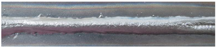 | 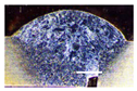 |
| 2 | 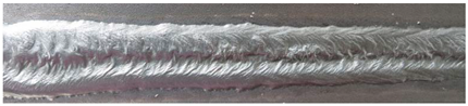 |  |
| 3 | 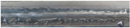 | 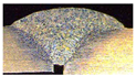 |
| 4 | 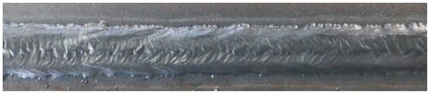 |  |
| 5 |  | 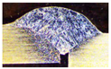 |
| 6 | 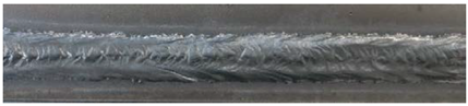 | 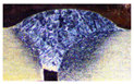 |
| Sample Number | Absorbed Energy (J) | ||||
|---|---|---|---|---|---|
| 1 | 2 | 3 | Average Value | Standard Deviation | |
| Base Metal | 53.5 | 53.8 | 54.7 | 54 | 0.5 |
| 1 | 17.9 | 18.1 | 18.6 | 18.2 | 0.3 |
| 2 | 29.7 | 30.1 | 29.6 | 29.8 | 0.2 |
| 3 | 11.8 | 11.8 | 12.4 | 12 | 0.3 |
| 4 | 30 | 29.9 | 30.1 | 30 | 0.1 |
| 5 | 17.5 | 17.3 | 16.8 | 17.2 | 0.3 |
| 6 | 26.8 | 26.9 | 27.3 | 27 | 0.2 |
© 2018 by the authors. Licensee MDPI, Basel, Switzerland. This article is an open access article distributed under the terms and conditions of the Creative Commons Attribution (CC BY) license (http://creativecommons.org/licenses/by/4.0/).
Share and Cite
Hu, Y.; Xue, J.; Dong, C.; Jin, L.; Zhang, Z. Effect of Additional Shielding Gas on Welding Seam Formation during Twin Wire DP-MIG High-Speed Welding. Appl. Sci. 2018, 8, 1658. https://doi.org/10.3390/app8091658
Hu Y, Xue J, Dong C, Jin L, Zhang Z. Effect of Additional Shielding Gas on Welding Seam Formation during Twin Wire DP-MIG High-Speed Welding. Applied Sciences. 2018; 8(9):1658. https://doi.org/10.3390/app8091658
Chicago/Turabian StyleHu, Yu, Jiaxiang Xue, Changwen Dong, Li Jin, and Zhanhui Zhang. 2018. "Effect of Additional Shielding Gas on Welding Seam Formation during Twin Wire DP-MIG High-Speed Welding" Applied Sciences 8, no. 9: 1658. https://doi.org/10.3390/app8091658
APA StyleHu, Y., Xue, J., Dong, C., Jin, L., & Zhang, Z. (2018). Effect of Additional Shielding Gas on Welding Seam Formation during Twin Wire DP-MIG High-Speed Welding. Applied Sciences, 8(9), 1658. https://doi.org/10.3390/app8091658