Article

Optimal Robust Control of Path Following and Rudder Roll Reduction for a Container Ship in Heavy Waves

School of Navigation, Guangdong Ocean University, Zhanjiang 524088, China
*
Author to whom correspondence should be addressed.
Appl. Sci. 2018, 8(9), 1631; https://doi.org/10.3390/app8091631
Submission received: 3 August 2018 / Revised: 4 September 2018 / Accepted: 10 September 2018 / Published: 12 September 2018
(This article belongs to the Special Issue Applied Sciences Based on and Related to Computer and Control)

Abstract

:
This paper presents an optimal approach to the multi-objective synthesis of path following and rudder roll reduction for a container ship in heavy waves. An improved line of sight principle with course-keeping in track-belt is proposed to guide the ship in accordance with marine practice. Concise robust controllers for the course and roll motion based on Backstepping and closed-loop gain shaping are developed. The control parameters have obvious physical significance. The determination method is given and much effort is made to guarantee the uniform asymptotic stability of the closed-loop systems by Lyapunov synthesis. Furthermore, the multi-objective optimization method a fast and elitist multi-objective genetic algorithm (NSGA-II) is used to solve the restrictions caused by the model perturbation, external disturbance and performance trade-off. Contrasting with the existing literature, the research strategy and control performance are more in line with marine engineering practice. Simulation results illustrate the performances and effectiveness of the proposed system.

1. Introduction

With the development of automation, ship autopilot has been used to keep course, change course, follow path and roll reduction for the purpose of safety and economy. Most merchant ship autopilots are underactuated mechanical systems, especially for the path following autopilots with rudder roll reduction (PFA-RRR), which have become an active research field [1,2]. For the PFA-RRR, some theoretical challenges hinder its widespread use on board surface ships, such as underactuated mechanism, non-minimum phase, performances trade-offs, the engineering significance of the control schemes and the uncertainties caused by the model perturbation and disturbances [3,4]. Underactuated ships are only equipped with rudders and propellers for yawing and surging motions, while there are no actuators for direct control of roll and sway motions. In accordance with the Brockett necessary condition, it is impossible to stabilize the underactuated ships by time invariant continuous control laws [5]. Several novel control strategies have been proposed to solve the path following of underactuated ships [6,7,8,9].
Although the effectiveness of the PFA has been proven, the marine surface ships with PFA are still negatively influenced by the wave-induced roll motions, such as cargo damage, personal seasickness, equipment operation failures and even ship capsizing. Therefore, PFA-RRR is of prominent safety significance for ship navigation in heavy seas, because most ships now are only equipped with rudders rather than other roll reduction devices, especially for merchant ships. The mechanism of RRR is to compensate the wave-induced rolling by rudder-induced initial inverse response [9,10]. Perez [3] and Perez and Blank [1] gave brief reviews of the developments of RRR from the earliest in 1970. However, these research developments and practical applications were mostly limited to naval vessels. Due to loading on upper deck, container ships have increased windward area and higher center of gravity, which result in higher risk in rough seas. Therefore, the PFA-RRR of a container ship is taken into consideration in this paper.
As reported by World Shipping Council, container ships around the world lost 2683 containers annually from 2011 to 2013. In addition, due to the rough sea conditions, MOL Comfort broke apart and sank on 17 June 2013, Svendborg Maersk lost 520 containers on 14 February 2014, and so on [10]. Why are these container ships not equipped with anti-roll fins? For merchant ships, a more decisive factor is cost vs. performance. Although the roll fin stabilizer performs well, it requires great installation costs, machine running consumption and hull space.
In the case of common merchant ship equipped with autopilot, when the heavy sea states affect the safety of the ship or cargo, the ship can only stop the autopilot steering and give up the planned route and then adopt the method of manual steering to head the wind and wave for the roll reduction, while the ship equipped with RRR can move on with reduced rolling impact, resulting in better safety and economic performance. All that is required is the upgrade of the steering gear’s quick performance and the addition of the controller module.
The selection of a suitable controller for PFA-RRR is an important technology. For ship motion control, much literature has studied the control of course, track and roll separately or jointly. Zhang et al. [11,12] used linear reduction of Backstepping and closed-loop gain shaping algorithm (CGSA) for ship course control. Zhang et al. [13] presented adaptive neural path-following control for underactuated ships in fields of marine practice. Perez and Blanke [1] gave a complete review of the research on ship roll reduction. The above studies performed well on the separate control of course and path following. In recent years, the study of rudder roll reduction has attracted more and more research on the development of full mission autopilot. Fang and Luo [14] designed separate and compact sliding mode controllers for straight-line path following and roll reduction in random waves. Fang et al. [15] studied proportion-derivative (PD) controllers based on the self-tuning neural network algorithm and the results indicate that the stabilizer fin control for roll reduction and the rudder control for track keeping in the seaway would be beneficial. A similar PD autopilot with RRR optimized by GA is presented in [16]. A model predictive control controller was proposed for the integrated path following and roll motion control problem by Liu et al. [2]. A two-time scale decomposition method was used to analyze and design the rudder roll stabilization by Ren et al. [17]. It is worth noting that, in the aforementioned study, the path following mainly focuses on the decrease of the tracking error, while, in the navigation practice of merchant ships, the track-belt is usually regarded as the reference standard for economic and safe manipulations.
The parameter scheme of multi-objective control design is usually not optimal, and multi-objective optimization (MO) methods have been applied to solve many engineering problems [18]. One of the most prominent Pareto evolutionary algorithms is a fast and elitist multi-objective genetic algorithm (NSGA-II) [19,20,21,22,23].
Inspired by previous research, a multi-purpose autopilot with path following, course and anti-rolling control is discussed in this paper. The main contributions of this work can be summarized as following:
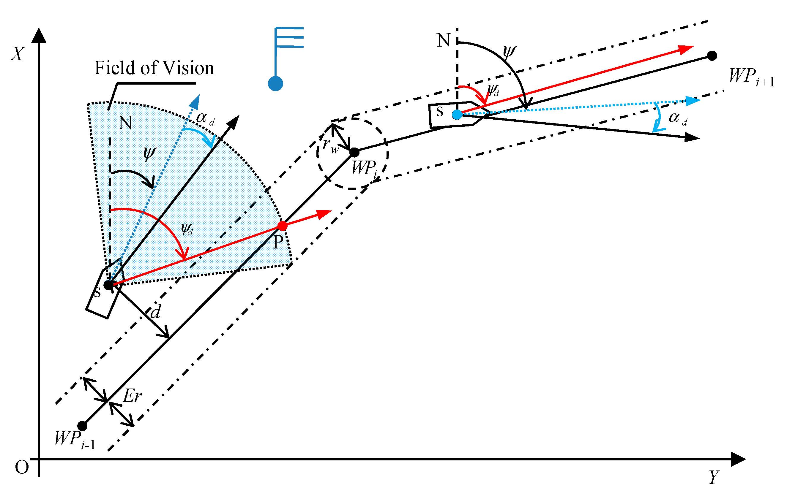
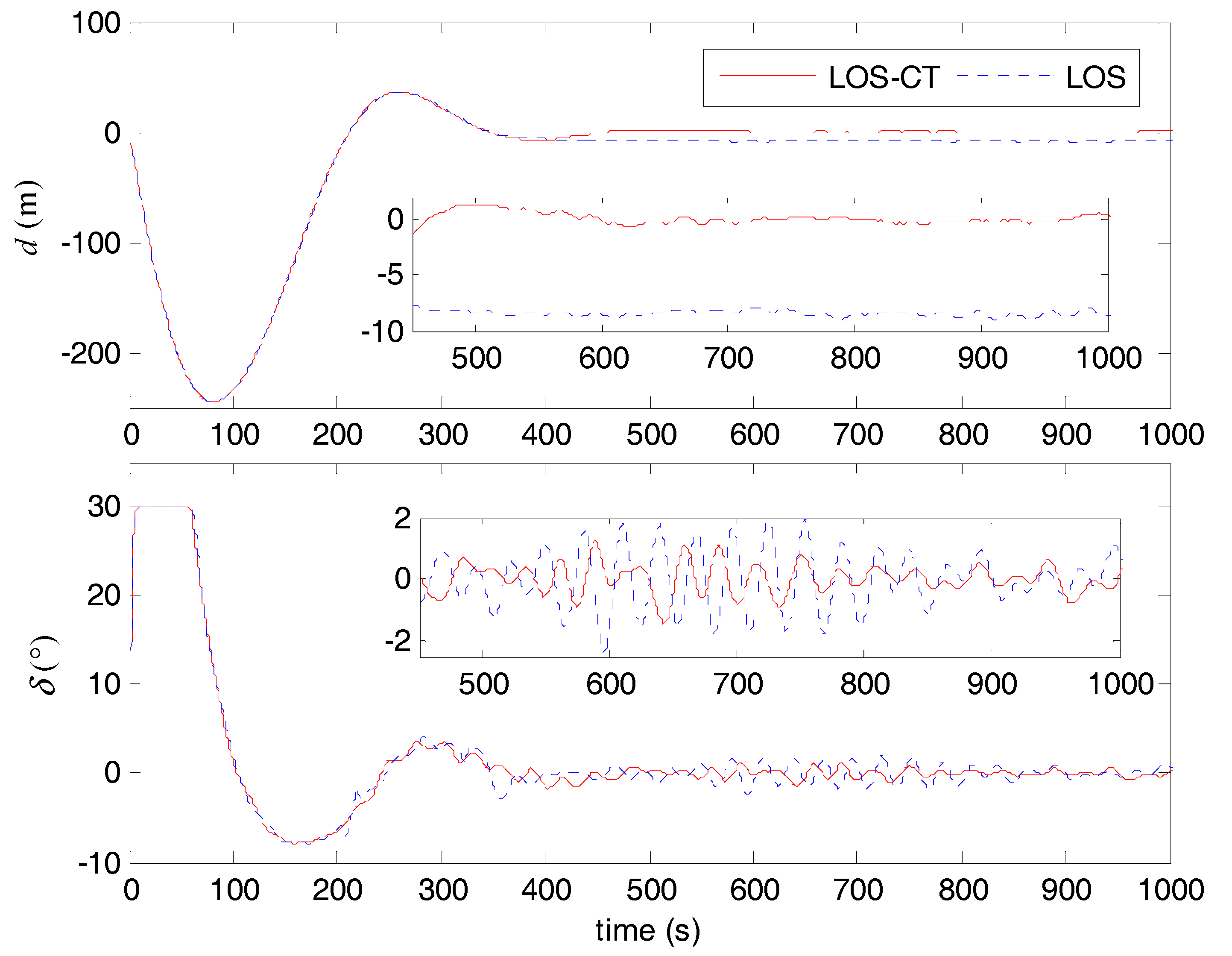
  • An improved line of sight (LOS) principle with course-keeping in track belt (LOS-CT) is firstly proposed to guide the ship in field of marine practice, which can reduce the rudder movements greatly by keeping the ship in track-belt rather than following the exact route.
  • The uniform asymptotic stability proofs of the developed concise robust control design for the course and roll are given. The control parameters have obvious physical significance and can be determined easily.
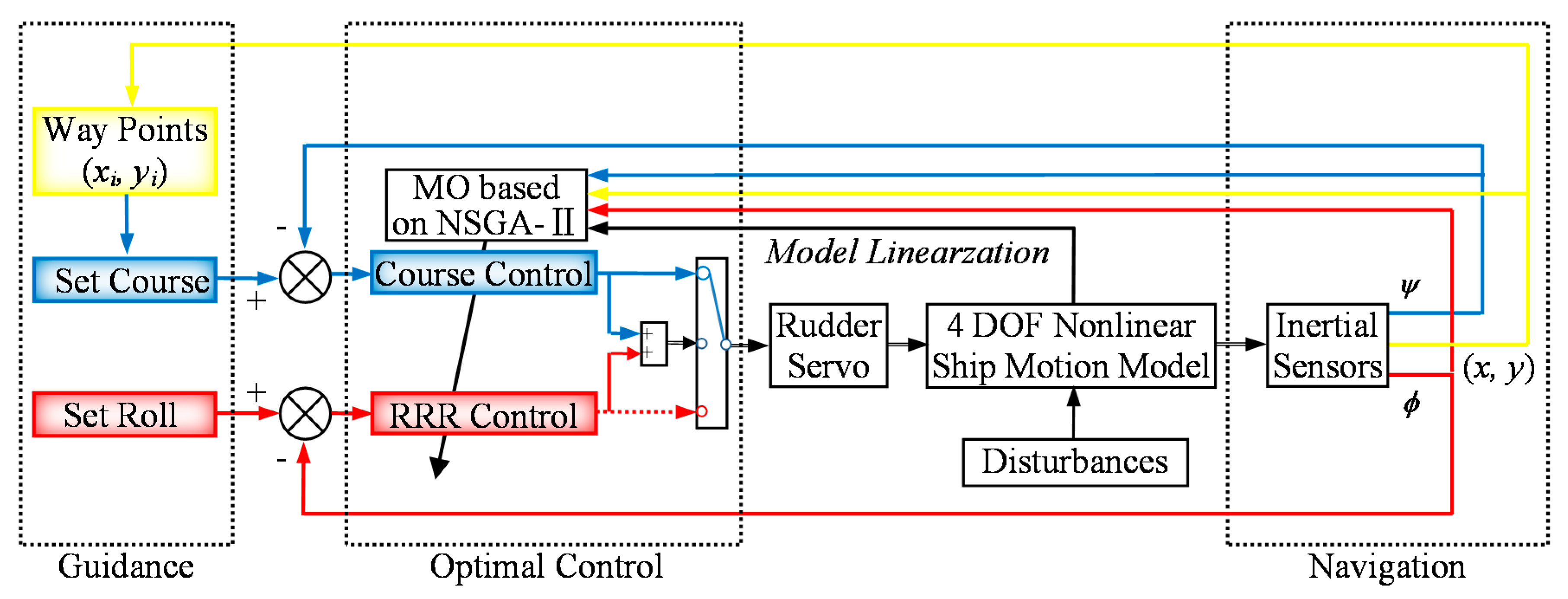
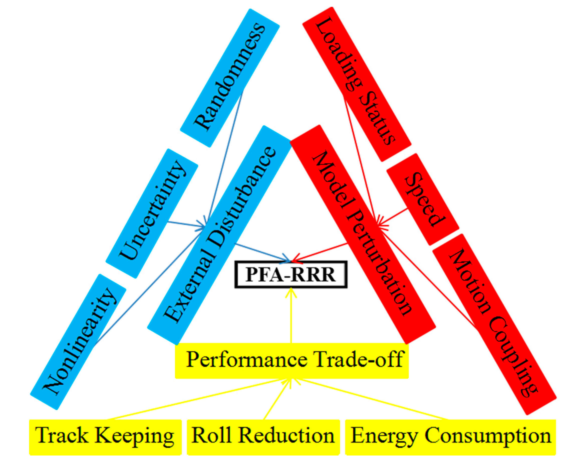
  • NSGA-II is recommended to solve the restrictions caused by the model perturbation, external disturbance and the performance trade-off for optimal control solution.
The rest of the article is organized as follows: Section 2 presents the analysis and transformation of the nonlinear model of a container ship. Section 3 is devoted to systematic procedures for LOS-CT and concise robust controller design, together with stability proofs. Section 4 provides multi-objective optimization and Pareto-optimal solutions of the control scheme. In Section 5, simulation results and discussion are presented. Section 6 draws the conclusion.

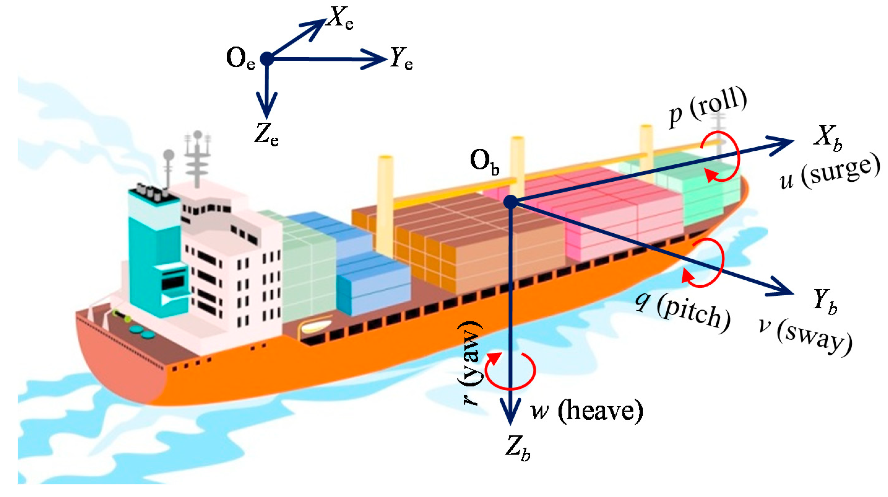
2. Analysis of Mathematical Model

To design control system for roll stabilization, it is necessary to incorporate roll motion to the horizontal plane model, i.e. restoring moment due to gravity and buoyancy must be included. The resulting maneuvering models including roll (surge, sway, yaw and roll) have been concluded in [4,10]. Thereinto, a four degrees of freedom (DOF) nonlinear model of a high speed container ship was proposed by Son and Nomoto [24,25], just as shown in Figure 1.
( m + m x ) u ˙ ( m + m y ) v r = X + τ X ( m + m y ) v ˙ + ( m + m x ) u r + m y α y r ˙ m y l y p ˙ = Y + τ Y ( I z + J z ) r ˙ + m y α y v ˙ = N Y x G + τ N ( I x + J x ) p ˙ m y l y v ˙ m x l x u r = J W Δ G M ϕ + τ J
where m denotes ship mass, and I x , I z denote the moments of inertia about the x and z axes, respectively. m x , m y and J x , J z denote the added mass and added moments of inertia. α y is the x-coordinate of the center of m y , while l x and l y are the z-coordinates of the centers of m x and m y respectively. x G is the distance of gravity center in front of the midship. ( ψ , ϕ ) are the yaw and roll angle in the earth-fixed coordinate frame. ( u , v , r , p ) denote surge, sway, yaw and roll velocities. ( τ X , τ Y , τ N , τ J ) are recognized as control inputs. W Δ is the ship displacement weight and G M is the transverse metacentric height. ( X , Y , N , J ) denote the hydrodynamic forces and moments, which are defined by third-order Taylor series expressions with small coefficients neglected.
Defining the state vector as x : = [ v , p , r , ϕ , ψ ] T , the linearized model of Equation (1) can be written in state-space form as follows
x ˙ = [ a 11 a 12 a 13 a 14 0 a 21 a 22 a 23 a 24 0 a 31 a 32 a 33 a 34 0 0 1 0 0 0 0 0 1 0 0 ] A x + [ b 11 b 12 b 1 r b 21 b 22 b 2 r b 31 b 32 b 3 r 0 0 0 0 0 0 ] B u y = [ 0 0 0 1 0 0 0 0 0 1 ] C x  
Assumption 1.
The dynamics between yaw and roll are decoupled in frequency domain. That is to say, the yaw motion caused by rolling is negligible, and vice versa.
Remark 1.
Assumption 1 is a common precondition for RRR control in the existing literature. The roll motion and related RRR rudder motion are of higher frequency, compared to yaw motion and regular course control rudder motion, which are typical inertial motions in lower frequency domain. Consequently, the course and RRR controllers can be designed separately in accordance with the additive principle.
Considering Assumption 1 and the container ship with one rudder, u = δ and b = [ b 11 b 12 b 13 0 0 ] T , the transfer functions can be derived as follows.
G ψ ( s ) = K ψ ( T 3 s + 1 ) s ( T 1 s + 1 ) ( T 2 s + 1 )  
G ϕ ( s ) = K ϕ ω ϕ 2 ( T 5 s + 1 ) ( T 4 s + 1 ) ( s 2 + 2 ξ ω ϕ s + ω ϕ 2 )  
where T i , i = 1 , 2 , 3 , 4 are time constants, K ϕ and K ψ are speed-related gains in rolling and yawing, ξ is the rolling damping coefficient, and ω ϕ is the rolling natural frequency.
Remark 2.
The parameters of Equations (3) and (4) are of typical navigation significance. However, it is obvious that the controller design based on the upper model has higher order.
It is well known that the Nomoto model in Equation (5) is widely used in the course autopilot design, and the practical applications show that it can express the inertial response of the course to the rudder simply and effectively, as indicated in Figure 2.
The roll response to rudder motion indicated in Figure 2 is divided into three typical parts, such as initial inward heeling, outward heeling in turning and roll oscillation [1,10]. RRR has been an effective method to stabilize roll amplitude using the initial inward heeling. Therefore, the control object model of rudder roll reduction can be simplified as Equation (6).
G R Y ( s ) = K s ( T s + 1 )  
G R R ( s ) = K ϕ ω ϕ 2 s 2 + 2 ξ ω ϕ s + ω ϕ 2  
where K , T are turning-ability index and turning-lag index separately. When designing course and RRR controllers, the parameters in Equations (5) and (6) have obvious physical significance, which is beneficial to the adaptive adjustment of parameters.

3. Design of Concise Robust Path-Following Control with RRR

To accomplish the PFA-RRR control design in field of marine practice, a novel guidance system is proposed to achieve better economic and safety performances in Section 3.1, and then one develops concise course and RRR control laws based on Backstepping for underactuated ships in Equation (1), whose parameters have typical physical meaning, and a method of parameter determination is given. The control flow is shown in Figure 3, and a selector switch is used to open or close the RRR.

3.1. Guidance System for Underactuated Ships

As shown in Figure 4, the purpose of the traditional guidance principle is to provide desired waypoints-based planned routes for marine ships [5,6,13]. The most used method at present is LOS, which can simulate the pilot’s vision field to determine the specific track tracking points. However, in marine practice, path planning will set a track error, thus forming a track-belt, if the ship is sailing within the track-belt, course-keeping can ensure the safety of navigation with less rudder movements, otherwise it is necessary to correct the track error, as shown in Figure 4. The advantage of this design is that both navigation safety and economy have been considered. For indirect straight-line path-following, LOS guidance principle is often incorporated with course-keeping autopilot to solve the way-point ship path following control problem. Consequently, an indirect path following system based on LOS with course-keeping in track-belt is brought up. Given the track error d and the range of track belt E r , the set course ψ d is defined as follows
d E r ,   ψ d = ψ W P i 1 W P i + α d d > E r ,   ψ d = ψ los + α d
where α d is the drift angle, W P 1 , W P 2 , W P i 1 , W P i are the waypoints in marine practice, ψ W P i 1 W P i is the direction angle from W P i 1 to W P i , and ψ LOS is defined by LOS guidance as the set course ψ SP from point S to point P shown in Figure 4. They can be obtained as the following:
ψ W i 1 W i = arctan ( y W P i y W P i 1 x W P i x W P i 1 ) ψ LOS = ψ SP = arctan ( y P y S x P x S )
As shown in Figure 4, ( x S , y S ) is the ship’s position, ( x P , y P ) is the cross position coordinates of the planned route and the vision field arc in LOS, which depends on the radius of the visual field R LOS . To obtain faster track error convergence, a variable R LOS is adopted to obtain faster track error convergence, as shown in Equation (9). Furthermore, when the ship enters the range of next waypoint within the turning radius r w , it is switched to the next route, and r w is set as 2L, with L the ship’s length.
R LOS = L ( 2 + d E r )  
The validity and superiority of the LOS-CT are proven Section 5. LOS-CT guidance performs as well as LOS near the waypoints. It is worth pointing out that LOS-CT reduces the rudder movements greatly by keeping the ship in track-belt rather than following the route.

3.2. Control Design

In accordance with Assumption 1 and Remark 1, separate control scheme applies two concise robust controllers to execute the path-following and roll stabilization by altering the rudder deflection, which is a recommended method [14,15]. One is combined with the LOS-CT guide system for path-following and the other is used for roll stabilization. Consequently, the resultant rudder angle δ for path-following and roll reduction is expressed as
δ = u c + u r  
where u c and u r are used for course control and RRR, respectively.

3.2.1. Concise Course Control Based on Backstepping

Theorem 1.
Considering the ship course keeping system in Equation (5), the proposed algorithm in Equation (11) based on the Backstepping method is capable of stabilizing the yaw motion and guaranteeing the uniformly asymptotic stability of the closed-loop course system.
u c = T K [ f ( x c 2 ) + ( 1 + k c 1 k c 2 ) e c + ( k c 1 + k c 2 ) e ˙ c ]  
where the course deviation e c = ψ ψ d , k c 1 ,   k c 2 are positive design parameters.
Proof. 
Set x c 1 = ψ , x c 2 = r , and then one can get the transformed model of Equation (5).
{ x ˙ c 1 = x c 2 x ˙ c 2 = f ( x c 2 ) + b c u c y c = x c 1  
where y c R , b c = K T , f ( x c 2 ) = 1 T x c 2 , which is a linear function.
Define z c 1 = x c 1 ψ d and z c 2 = x c 2 α ( z c 1 ) , and then one can get
z ˙ c 1 = x ˙ c 1 ψ ˙ d = x c 2 ψ ˙ d = z c 2 + α ( z c 1 ) ψ ˙ d  
α ( z c 1 ) is chosen as an intermediate control function defined as
α ( z c 1 ) = ψ ˙ d k c 1 z c 1  
and
α ˙ ( z c 1 ) = ψ ¨ d k c 1 z ˙ c 1  
where k c 1 > 0 is one design constant. Substituting Equation (14) into Equation (13), one can get
z ˙ c 1 = k c 1 z c 1 + z c 2  
Considering the following Lyapunov function candidate
V c = 1 2 z c 1 2 + 1 2 z c 2 2  
V ˙ c = k c 1 z c 1 2 + z c 2 [ f ( x c 2 ) α ˙ ( z c 1 ) + z c 1 + b c u c ]  
To guarantee V ˙ c 0 , one can choose the actual control function as follows
u c = 1 b c ( α ˙ ( z c 1 ) f ( x c 2 ) z c 1 k c 2 z c 2 )  
where k c 2 > 0 is another design constant. Substituting Equation (19) into Equation (18), one can get
V ˙ c = k c 1 z c 1 2 k c 2 z c 2 2 < 0 ,   z c 1 0 , z c 2 0  
In accordance with Lyapunov stability theory, the course control system can be stabilized by the control law in Equation (19), and all the variables in course control loop are of uniformly asymptotic stability with an equilibrium point [ x c 1 , x c 2 ] = [ ψ d , ψ ˙ d ] .
Setting the reference course as ψ d and ψ ¨ d = 0 , and substituting Equation (15) into Equation (19), the control law is transformed into Equation (21). It is obvious that the essence of the above Backstepping control design is to compensate and stabilize f ( x c 2 ) with a PD-type control law υ c .
u c = 1 b c [ f ( x c 2 ) + ( 1 + k c 1 k c 2 ) ( x c 1 ψ d ) + ( k c 1 + k c 2 ) ( x ˙ c 1 ψ ˙ d ) ] = T K [ f ( x c 2 ) + ( 1 + k c 1 k c 2 ) e c + ( k c 1 + k c 2 ) e ˙ c ] = T K [ f ( x c 2 ) + υ c ]
This ends the proof of Theorem 1. □

3.2.2. Concise RRR Control Based on Backstepping

Theorem 2.
Considering the ship RRR system in Equation (6), the proposed algorithm in Equation (22) based on the Backstepping method is capable of stabilizing the roll motion and guaranteeing the uniformly asymptotic stability of the closed-loop RRR system.
u r = 1 K ϕ ω ϕ 2 [ ( 2 ξ ω ϕ p + ω ϕ 2 p d t ) + ( 1 + k r 1 k r 2 ) e r + ( k r 1 + k r 2 ) e ˙ r ]  
where the roll angle deviation e r = ϕ ϕ d , k r 1 ,   k r 2 are positive design parameters.
Proof. 
Set x r 1 = ϕ , x r 2 = p , and then the roll motion model in Equation (6) is rewritten as follows
{ x ˙ r 1 = x r 2 x ˙ r 2 = g ( x r 2 ) + b r u r y r = x r 1  
where y r R , b r = K ϕ ω ϕ 2 , g ( x r 2 ) = ( 2 ξ ω ϕ x r 2 + ω ϕ 2 x r 2 d t ) , which is a nonlinear function of x r 2 .
Define z r 1 = x r 1 ϕ d and z r 2 = x r 2 β ( z r 1 ) , and then one can get
z ˙ r 1 = x ˙ r 1 ϕ ˙ d = x r 2 ϕ ˙ d = z r 2 + β ( z r 1 ) ϕ ˙ d  
β ( z r 1 ) is chosen as an intermediate control function defined as
β ( z r 1 ) = ϕ ˙ d k r 1 z r 1  
and
β ˙ ( z r 1 ) = ϕ ¨ d k r 1 z ˙ r 1  
Substituting Equation (25) into Equation (24), one can get
z ˙ r 1 = k r 1 z r 1 + z r 2  
Considering the following Lyapunov function candidate
V r = 1 2 z r 1 2 + 1 2 z r 2 2  
Then, one can get the time derivative of V r
V ˙ r = k r 1 z r 1 2 + z r 2 [ g ( x r 2 ) β ˙ ( z r 1 ) + z r 1 + b r u r ]  
To guarantee V ˙ r 0 , actual control function is chosen as follows
u r = 1 b r ( β ˙ ( z r 1 ) g ( x r 2 ) z r 1 k r 2 z r 2 )  
Substituting Equation (30) into Equation (29), one can get
V ˙ r = k r 1 z r 1 2 k r 2 z r 2 2 < 0 ,   z r 1 0 , z r 2 0  
In accordance with Lyapunov stability theory, the RRR control system can be stabilized by the control law in Equation (30), and all the variables in RRR control loop are of uniformly asymptotic stability with an equilibrium point [ x r 1 , x r 2 ] = [ ϕ d , ϕ ˙ d ] .
Substituting Equation (26) into Equation (30), the control law is transformed into Equation (32).
u r = 1 b r [ g ( x r 2 ) + ( 1 + k r 1 k r 2 ) ( x r 1 ϕ d ) + ( k r 1 + k r 2 ) ( x ˙ r 1 ϕ ˙ d ) ] = 1 K ϕ ω ϕ 2 [ ( 2 ξ ω ϕ p + ω ϕ 2 p d t ) + ( 1 + k r 1 k r 2 ) e r + ( k r 1 + k r 2 ) e ˙ r ] = 1 K ϕ ω ϕ 2 [ g ( x r 2 ) + υ r ]
This ends the proof of Theorem 2. □
Remark 3.
The essences of the separate control laws in Equations (21) and (32) based on Backstepping are to compensate the system’s linearity or nonlinearity and to stabilize the control loops by PD controllers υ c and υ r . Furthermore, the aforementioned consideration leads to a control law with concise form which is applicable for linear and nonlinear systems. However, the design parameters of k c 1 , k c 2 , k r 1 , k r 2 can only be obtained by trial and error, which are of little engineering significance and difficult to be determined for robust and optimal performances.

3.2.3. Control Parameters Determining

To guarantee the robust performance of the aforementioned control laws, a novel method to determine the design parameters is developed in this section. By virtue of the first-order CGSA [11,26,27], a simple linear robust controller υ is obtained as following.
1 T L s + 1 = G υ 1 + G υ  
υ = 1 G T L s  
where 1 / T L stands for the natural frequency of the control loop. For course control loop, it should be smaller than the interference band, i.e., the frequency band of wave 0.3–1.25 rad/s. For RRR control loop, 1 / T L is recommended to be the natural frequency of ship roll motion, which can be estimated by empirical formula.
Obviously, the transfer function models in Equations (5) and (6) are strictly rational proper fraction function, with a standard form as Equation (35). It is noteworthy that engineering control objects can usually be transformed into the form as Equation (35) by model reduction or Bode plots approximation. Then, a typical PID controller is obtained by substituting Equation (35) into Equation (34).
G ( s ) = b a 2 s 2 + a 1 s + a 0  
where a 0 , a 1 , a 2 and b are constant coefficients.
υ = a 2 s b T L + a 1 b T L + a 0 b T L s = K d s + K p + K i / s  
Based on Theorems 1 and 2, the course and RRR control loops are uniformly asymptotic stable at set course ψ d and roll angle ϕ d respectively. That is to say, the steady-state errors satisfy lim t e c ( t ) = 0 and lim t e r ( t ) = 0 . Consequently, the integral control parameter K i can be ignored. Then, Equation (36) can be rewritten as Equation (37).
υ = a 2 s b T L + a 1 b T L  
Defining 1 / T L c ,   1 / T L r as the natural frequency of course and RRR loops, respectively, and substituting the parameters of Equations (5) and (6) into (37), one can get
υ c = 1 K T L c + T K T L c s  
υ r = 2 ξ K ϕ ω ϕ T L r + s K ϕ ω ϕ 2 T L r  
Comparing Equations (38) and (39) with Equations (21) and (32), one can obtain the design parameters by solving the equation sets as follows
{ 1 + k c 1 k c 2 = 1 K T L c k c 1 + k c 2 = T K T L c  
{ 1 + k r 1 k r 2 = 2 ξ K ϕ ω ϕ T L r k r 1 + k r 2 = 1 K ϕ ω ϕ 2 T L r  
By virtue of ship maneuvering empirical knowledge and the first-order CGSA, the design parameters k c 1 , k c 2 , k r 1 , k r 2 can be exactly determined in accordance with system parameters K , T , K ϕ , ξ , ω ϕ , T L c , T L r , which have clear physical significance and domains. However, the optimal performances in different loading status or sea conditions cannot be guaranteed.

4. Multi-Objective Optimization Based on NSGA-II

Based on above control design, a PFA-RRR is developed with obvious engineering significance. However, the practical application of PFA-RRR is still trapped in the restrictions caused by the model perturbation, external disturbance and the performance trade-off (see Figure 5). To achieve optimal performances and solve the trade-offs among them, multi-objective optimization is recommended to get the control parameter strategy library by off-line optimization in this note.
Multi-objective optimization methods have been applied to solve many engineering problems. One of the most prominent Pareto evolutionary algorithms is NSGA-II. To achieve the optimal performances, multi-objective optimization based on NSGA-II [28,29] is firstly used to solve the set of Pareto-optimal solutions of the aforementioned design parameters, and each solution represents an optimal feasible control strategy that cannot be outrun by any other considering all criteria.
Three criteria are considered for the optimization. The minimum track error and roll amplitude are the most important control objectives. However, there is an obvious trade-off between them. On the other hand, the minimum movement of steering gear is considered as another criterion. The criteria are defined as follows
min ( f d , f ϕ , f δ ) f d = 1 N s i = 1 N ( d i ) 2 f ϕ = 1 N s i = 1 N ( ϕ i ) 2 f δ = 1 N s i = 1 N ( δ i ) 2
where f d , f ϕ , f δ stands for the root mean square (RMS) values of d i , ϕ i , δ i . N s is the sample number. Constraints are as follows.
0 d i < E r 0 ϕ i < ϕ max | δ | 30 ° | δ ˙ | 10 ° / s
The problem is considered for searching the optimal control strategies of PFA-RRR as a Pareto-front. NSGA-II is used to find the optimal solutions set.
Figure 6 illustrates the Pareto optimal set distribution, which appears two typical bands. Firstly, the path following performance varies from 2 to 4 m with a 0.5° perturbation of roll angle and rudder movement. Secondly, when the roll reduction rate doubles, the track error only increases 0.2 m with a triple rudder movement.
Remark 4.
The performance perturbation between f d and f ϕ is limited to a small positive amount, which indicates the trade-off between the two is little and tolerable. Note that, the trade-off between RRR and course is obvious [14,15,16] but does not pass on to the indirect path following control with RRR. On the other hand, the performance of RRR is directly related to the rudder servomovements, and higher RRR rate results in greater weight in rudder movement. In other words, using the proposed control strategies, the rudder can achieve bothgood tracking accuracy and high RRR rate with a substantial increase inrudder movements.

5. Simulation Examples

5.1. Configurations

In this section, simulation examples are presented to illustrate the effectiveness of the control scheme in fields of marine practice. Based on the LOS-CT guidance system in Section 3.1, the planed route consists of waypoints WP1 (0, 0), WP2 (8000, 8000), WP3 (16,000, 0), WP4 (18,000, 11,000), WP5 (8000, 19,000), and WP6 (−2000, 11,000), with the unit m. To study the application value of the proposed control schemes on widely merchant ships, the simulation object is a container ship “SR108”, which is defined in Section 2. As shown in Figure 1, the length is L = 175 m , together with breadth B s = 25.4 m , displacement D = 21 , 222 tons , mean draft d m = 8.5 m , block coefficient C b = 0.559 , propeller revolutions P r = 70 , metacentric height G M = 0.3 m , and forward speed U 0 = 7.3 m / s . Detailed hydrodynamic force derivatives can be found [2,3].
In the simulation experiments, the impact of the wind on the ship course can be divided into two parts: the mean wind and the fluctuating wind. The fluctuating wind is stochastic, which is considered as white noise [30]. In marine practice, the effect of mean wind is taken as leeway drift, which can be expressed by an equivalent rudder angle δ l d as follows.
δ l d = C l d ( S w U 0 ) 2 sin α w  
where C l d denotes the leeway drift coefficient, S w denotes the wind speed, and α w denotes the relative wind angle. The wind force is set to Beaufort No. 6, S w is about 12 m/s, the set value of C l d is 0.05, and α w is 000°. The influence of current on ship’s position and speed can be defined as Equation (45), with the current speed U c 2 kn and the current direction α c 225°.
{ x ˙ = U sin ( ψ ) + U c sin ( α c ) y ˙ = U cos ( ψ ) + U c cos ( α c )  
The wave-induced roll motion is produced by Pierson–Moskowitz (PM) spectrum driven by white noise. Supposing y w = x w 2 = x ˙ w 1 , one can obtain the wave-induced rolling as follows
[ x ˙ w 1 x ˙ w 2 ] = [ 0 1 T e 2 2 ξ T e 1 ] [ x w 1 x w 2 ] + [ 0 K w ] W n y w = [ 0 1 ] [ x w 1 x w 2 ]
As shown in Figure 7, the sea state is set to 5, the significant wave height H is about 2.5 m, the wave encountering frequency T e 1 is 0.8378 rad/s, the damping ratio ξ is 0.05, and the wave strength factor K w is H / 1000 .
The controllers in Section 3 are optimized by a real-coded NSGA-II, with the population size 100, mutation operator 20, crossover operator 20, and initial searching spaces [0.01 100]. The stopping generation number 100. The optimization results are illustrated by Pareto optimal set distribution in Figure 6, and a parameter set is selected with the smallest d and ϕ , and highest rudder movements δ .
Due to the high cost and difficulty of the actual ship verification, the nonlinear ship model in Section 2 is implemented to test the effectiveness of the proposed control schemes. The roll reduction rate is defined as follows
R r r r = ϕ n r r r ϕ r r r ϕ n r r r × 100 %  
where ϕ n r r r is the STD value of original wave-induced roll motions, and ϕ r r r is the STD value of roll motions after the actuation of RRR.
To further study the robustness and effectiveness of the control system in response to different sea conditions, more simulation tests have been done in different sea states with wave-induced maximum roll angle ranging from 10 to 35°.

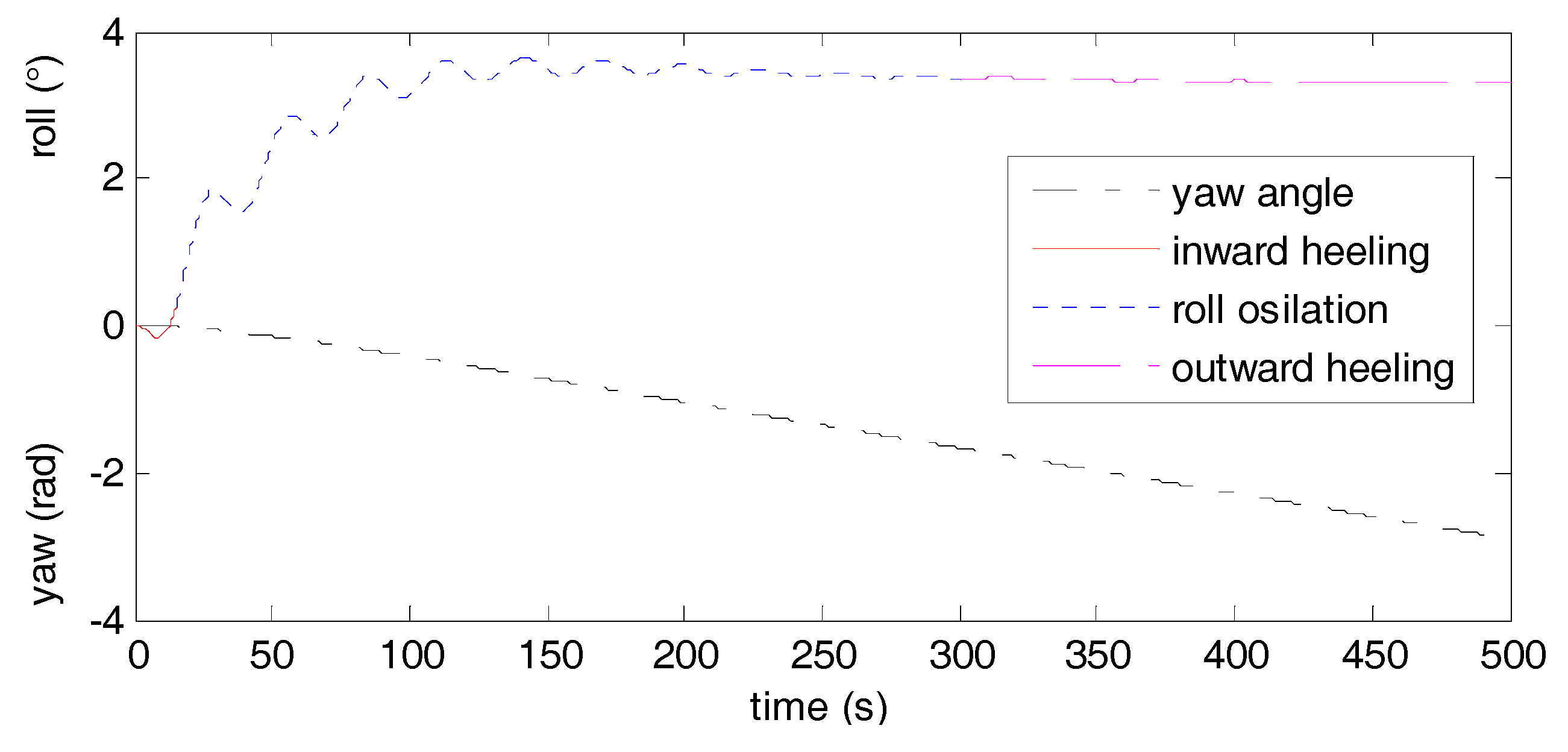
5.2. Simulation Results and Discussion

The simulation results of the PFA with RRR in a seaway are shown in Figure 8, Figure 9 and Figure 10, which indicate that the proposed scheme can achieve good performances of path following, course changing, course keeping and roll reduction. Figure 8 shows the test routes in X-Y plane. It illustrates that the PFA with RRR control is well established despite the existence of model perturbation and sea state disturbances. Figure 9 indicates the contrast experimental results of LOS-CT and LOS between WP1 and WP2. Figure 10 demonstrates the position errors, course angles, roll angles and the rudder efforts. For the motions before and after the RRR is activated, the comparative analysis is carried out according to the two stages of the track maintenance and the turning near the waypoints, as shown in Table 1. During the path following stage, the LOS-CT scheme and course controller performs well with an energy-efficient steering gear input. As shown in Figure 9, the LOS-CT guidance reduces the rudder movements 48.7% under the guarantee of path following accuracy. When the RRR is activated, the roll amplitude is reduced by 48.5% with about 10 times rudder movement, and both the track error and the course error have increased by nearly fivefold, but they are all within the rational range of navigation practice. During the ship’s turning near the waypoints, the system responses quickly with a reasonable steering mode, the track and course show certain overshoots. Although the roll reduction is negligible because of the outward heeling in turning, the activation of RRR attenuates the overshoots of track and course greatly by 47.6% and 94.9%, respectively. Furthermore, it can be seen from the variation chart of ship speed that, when the ship turns, there is obvious speed drop, and when the RRR is turned on, the turning speed drop is reduced, while the speed drop of the path following stage appears.
As shown in Table 2, the control performances of PFA-RRR in different sea states prove the robustness and effectiveness. When the wave-induced disturbances get bigger, the accuracy of track tracking is worse, the rudder roll reduction is better in less than 30°, and the rudder movements increases gradually. It is noted that the reduction rate is significant but decreases when the maximum roll angle reaches 35 degrees.

6. Conclusions

This paper focuses on the optimal path following autopilot with rudder roll reduction control in the field of marine practice. An improved LOS-CT guidance law is developed to solve the practical waypoint based path following problems, and then concise robust course and RRR control laws based on Backstepping are proposed for underactuated ships with stability proofs and determination method of parameters. Furthermore, multi-objective optimization method NSGA-II is used to achieve optimal performances and solve the trade-offs among them, and the Pareto-optimal solutions reveal the detailed trade-offs, especially the trade-off between RRR and rudder motion, which has severely restricted the promotion of RRR. Contrasting with existing literature, the research strategy and control performance are more in line with marine engineering practice. Simulation results have illustrated the performances and effectiveness of the proposed system.

Author Contributions

Conceptualization, L.W.; Funding acquisition, S.W. and L.W.; Investigation, S.W. and L.W.; Methodology, S.W. and L.W.; Resources, L.W.; Software, S.W. and Z.Q.; Writing—original draft, L.W.; and Writing—review and editing, S.W., L.W., Z.Q. and F.L.

Funding

This work was supported by Natural Science Foundation of Guangdong province (Grant 2015A030310131); Scientific Research Start-up Funds of Guangdong Ocean University (Grants E15031 and R17012); Characteristic Innovation Projects of Guangdong province (Grants 2017KTSCX088 and 2017KTSCX092); and College Student Innovation and Entrepreneurship Training Program of Guangdong province (Grant 530002001095).

Acknowledgments

The authors gratefully acknowledge the helpful comments and suggestions of the reviewers, which have improved the presentation.

Conflicts of Interest

The authors declare no conflict of interest.

Abbreviations

The abbreviations and symbols adopted throughout the paper are listed:
PHApath following autopilot
CGSAclosed-loop gain shaping algorithm
RRRrudder roll reduction
MOmulti-objective optimization
LOSline of sight
DOFdegree of freedom
CTtrack belt
PMPierson–Moskowitz
RMSroot mean square
STDstandard deviation
m ship mass
W Δ ship displacement weight
L ship’s length
u r rudder angle of RRR control
B s ship’s width
u c rudder angle of course control
D ship’s displacement
R r r r roll reduction rate
d m mean draft
ϕ n r r r STD of wave-induced roll motions
T i time constants
ϕ r r r STD of roll motions with RRR
ξ damping ratio
T e 1 wave encountering frequency
ω ϕ rolling natural frequency
ψ W i 1 W i direction from W i 1 to W i
C l d leeway drift coefficient
ψ LOS set course by LOS guidance
δ l d equivalent rudder angle
ψ SP from point S to point P
S w denotes the wind speed
R LOS radius of the visual field
α w relative wind angle
1 / T L natural frequency of the control loop
W P i way points
1 / T L c natural frequency of course loop
K w wave strength factor
1 / T L r natural frequency of RRR loop
K turning-ability index
m x , m y added mass of inertia about x, y
T turning-lag index
J x , J z added moments of inertia about x, z
E r range of track-belt
I x , I z moment of inertia about x, z
ψ d set course
l x , l y z-coordinates of the centers of m x , m y
α d drift angle
e c , e r deviation of course and roll
C b block coefficient
k c 1 ,   k c 2 positive design parameters
P r propeller revolutions
k r 1 ,   k r 2 positive design parameters
U 0 forward speed
υ , υ c , υ r linear robust controllers
U c current speed
ψ d , ϕ d set course and set roll angle
α c current direction
ψ , ϕ yaw and roll angle
H significant wave height
a 0 , a 1 , a 2 constant coefficients
r w turning radius
b , b c , b r constant coefficients
ϕ max maximum of roll angle
d i , ϕ i , δ i sample values of d , ϕ , δ
N s sample number
u , v , r , p surge, sway, yaw and roll velocities
δ rudder angle
X , Y , N , J hydrodynamic forces and moments
K ϕ speed-related gains in roll
τ X , τ Y , τ N , τ J control inputs
K ψ speed-related gains in yaw
f d , f ϕ , f δ RMS values of d i , ϕ i , δ i
G M metacentric height
( x S , y S ) ship’s position S coordinates
α y x-coordinate of m y center
( x P , y P ) cross position P coordinates of the planned route and the vision field arc

References

  1. Perez, T.; Blanke, M. Ship roll damping control. Annu. Rev. Control 2012, 36, 129–147. [Google Scholar] [CrossRef] [Green Version]
  2. Liu, C.; Sun, J.; Zou, Z. Integrated Line of Sight and Model Predictive Control for Path Following and Roll Motion Control Using Rudder. J. Ship Res. 2015, 59, 99–112. [Google Scholar] [CrossRef]
  3. Perez, T. Ship Motion Control: Course Keeping and Roll Stabilization Using Rudder and Fins; Springer: Berlin, Germany, 2005. [Google Scholar]
  4. Fossen, T.I. Handbook of Marine Craft Hydrodynamics and Motion Control; Wiley: New York, NY, USA, 2011. [Google Scholar]
  5. Brockett, R.; Millman, R.; Sussman, H. Differential Geometric Control Theory; Birkhauser: Boston, MA, USA, 1983. [Google Scholar]
  6. Ghommam, J.; Mnif, F.; Derbel, N. Global stabilization and tracking control of underactuated surface vessels. IET Control Theory Appl. 2010, 4, 71–88. [Google Scholar] [CrossRef]
  7. Oh, S.-R.; Sun, J. Path following of underactuated marine surface vessels using line-of-sight based model predictive control. Ocean Eng. 2010, 37, 289–295. [Google Scholar] [CrossRef]
  8. Khaled, N.; Chalhoub, N.G. A self-tuning guidance and control system for marine surface vessels. Nonlinear Dyn. 2013, 73, 897–906. [Google Scholar] [CrossRef]
  9. Fossen, T. Guidance and Control of Ocean Vehicles; John Wiley and Sons: New York, NY, USA, 1994. [Google Scholar]
  10. Wang, L.; Wang, S.; Liu, J.; Han, J. Robust PID control of course-keeping with RRS and its MCO based on NSGA-II. ICIC Express Lett. 2015, 9, 3113–3119. [Google Scholar]
  11. Zhang, X.K.; Yang, G.; Zhang, Q.; Zhang, G.; Zhang, Y. Improved Concise Backstepping Control of Course Keeping for Ships Using Nonlinear Feedback Technique. J. Navig. 2017, 70, 1–14. [Google Scholar] [CrossRef]
  12. Zhang, X.K.; Zhang, Q.; Ren, H.X.; Yang, G.P. Linear reduction of backstepping algorithm based on nonlinear decoration for ship course-keeping control system. Ocean Eng. 2018, 147, 1–8. [Google Scholar] [CrossRef]
  13. Zhang, G.; Zhang, X.; Zheng, Y. Adaptive neural path-following control for underactuated ships in fields of marine practice. Ocean Eng. 2015, 104, 558–567. [Google Scholar] [CrossRef]
  14. Fang, M.C.; Luo, J.H. On the track keeping and roll reduction of the ship in random waves using different sliding mode controllers. Ocean Eng. 2007, 34, 479–488. [Google Scholar] [CrossRef]
  15. Fang, M.C.; Lin, Y.H.; Wang, B.J. Applying the PD controller on the roll reduction and track keeping for the ship advancing in waves. Ocean Eng. 2012, 54, 13–25. [Google Scholar] [CrossRef]
  16. Wang, L.; Wang, S. Course-keeping Autopilot with RRD Based on GA-PD Adaptive Optimization. Lect. Notes Electr. Eng. 2013, 210, 695–702. [Google Scholar]
  17. Ren, R.; Zou, Z.; Wang, X. A two-time scale control law based on singular perturbations used in rudder roll stabilization of ships. Ocean Eng. 2014, 88, 488–498. [Google Scholar] [CrossRef]
  18. Bingul, Z. Adaptive genetic algorithms applied to dynamic multiobjective problems. Appl. Soft Comput. 2007, 7, 791–799. [Google Scholar] [CrossRef]
  19. Liu, T.; Gao, X.; Wang, L. Multi-objective optimization method using an improved NSGA-II algorithm for oil–gas production process. J. Taiwan Inst. Chem. Eng. 2015, 57, 42–53. [Google Scholar] [CrossRef]
  20. Chaine, S.; Tripathy, M.; Satpathy, S. NSGA-II based optimal control scheme of wind thermal power system for improvement of frequency regulation characteristics. Ain Shams Eng. J. 2015, 6, 851–863. [Google Scholar] [CrossRef]
  21. Kalaivani, L.; Subburaj, P.; Iruthayarajan, M.W. Speed control of switched reluctance motor with torque ripple reduction using non-dominated sorting genetic algorithm (NSGA-II). Int. J. Electr. Power Energy Syst. 2013, 53, 69–77. [Google Scholar] [CrossRef]
  22. Kashani, H.N.; Rafiei, S.M.R. Optimal Control of Active Power Filters using Fractional Order Controllers Based on NSGA-II Optimization Method. Int. J. Electr. Power Energy Syst. 2014, 63, 1008–1014. [Google Scholar] [CrossRef]
  23. Zamanifar, M.; Fani, B.; Golshan, M.E.H.; Karshenas, H.R. Dynamic modeling and optimal control of DFIG wind energy systems using DFT and NSGA-II. Electr. Power Syst. Res. 2014, 108, 50–58. [Google Scholar] [CrossRef]
  24. Son, K.; Nomoto, K. On the Coupled Motion of Steering and Rolling of a High Speed Container Ship. J. Jpn. Soc. Nav. Archit. Ocean Eng. 1981, 150, 232–244. [Google Scholar] [CrossRef]
  25. Son, K.H.; Nomoto, K. On the Coupled Motion of Steering and Rolling of a Ship in Following Seas. J. Jpn. Soc. Nav. Archit. Ocean Eng. 1982, 152, 180–191. [Google Scholar] [CrossRef]
  26. Zhang, X.; Zhang, G. Stabilization of pure unstable delay systems by the mirror mapping technique. J. Process Control 2013, 23, 1465–1470. [Google Scholar] [CrossRef]
  27. Wang, L. Determining robust parameters in stabilizing set of backstepping based nonlinear controller for ship course keeping comment. Int. J. Marit. Eng. 2016, 158, A275–A276. [Google Scholar]
  28. Wang, L.; Zhang, X. Improved closed-loop gain shaping algorithm and its application in RRS. ICIC Express Lett. 2011, 5, 4215–4220. [Google Scholar]
  29. Arab Tehrani, K.; Amirahmadi, A.; Rafiei, S.M.R.; Griva, G.; Barrandon, L.; Hamzaoui, M.; Rasoanarivo, I.; Sargos, F.M. Design of fractional order PID controller for boost converter based on multi-objective optimization. In Proceedings of the 14th International Power Electronics and Motion Control Conference (EPE-PEMC), Ohrid, Macedonia, 6–8 September 2010. [Google Scholar]
  30. Wang, L.; Wang, S. High Degree Cubature Federated Filter for Multisensor Information Fusion with Correlated Noises. Math. Probl. Eng. 2016, 2016, 5252487. [Google Scholar] [CrossRef]
Figure 1. Ship’s body fixed and earth fixed coordinate frames.
Applsci 08 01631 g001
Figure 2. Ship’s course and roll response to rudder motion of port 5°.
Applsci 08 01631 g002
Figure 3. Signal flow indication for guidance, optimal control and navigation.
Applsci 08 01631 g003
Figure 4. The guidance of improved LOS with course-keeping in track-belt.
Applsci 08 01631 g004
Figure 5. The restrictions of model perturbation, external disturbance and the performance trade-off.
Applsci 08 01631 g005
Figure 6. The Pareto optimal sets distribution for PFA-RRR based on NSGA-II.
Applsci 08 01631 g006
Figure 7. The wave graphs of sea state 5.
Applsci 08 01631 g007
Figure 8. The path following results in X-Y plane.
Applsci 08 01631 g008
Figure 9. The contrast experimental results of LOS-CT and LOS between WP1 and WP2.
Applsci 08 01631 g009
Figure 10. The results of track error, course, roll angle, ship speed and rudder efforts.
Applsci 08 01631 g010
Table 1. The standard deviation (STD) values of the control performances with the RRR on/off.
AutopilotPath FollowingWaypoint Turning
d (m) e c (°) ϕ (°) δ (°) d (m) ψ (°) ϕ (°) δ (°)
RRR-OFF0.470.225.690.6586.323.134.6414.03
RRR-ON2.12 ↑0.90↑2.93↓7.61↑45.24↓0.16↓4.61↓13.81↓
Table 2. Control performances of PFA-RRR in different sea states.
Sea State ϕ max (°)10.015.020.025.030.035.0
ϕ std (°)3.95.26.87.79.810.3
d (m)1.41.92.62.93.35.9
R r r (%)40.944.749.250.557.043.8
δ (°)6.07.38.59.310.313.8

