Simultaneous Prevention of Rotational and Translational Slip for a Humanoid Robot

 ,
, 
Abstract
1. Introduction
- (1)
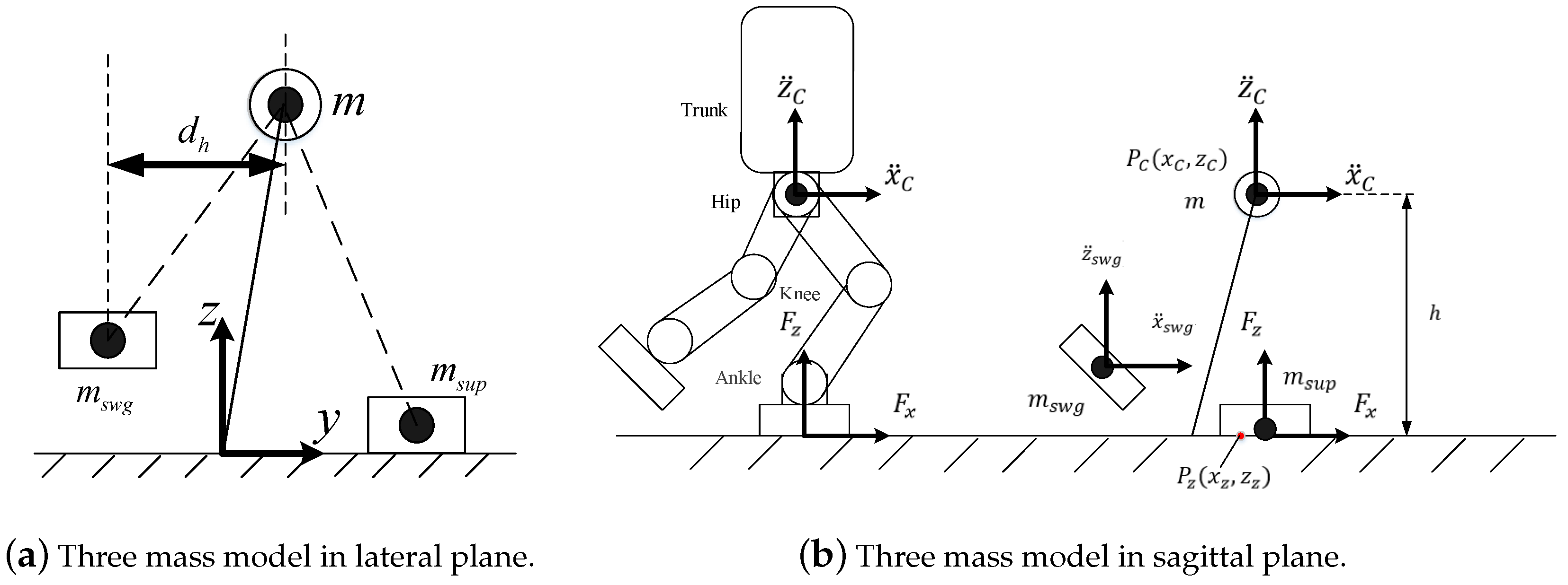
- A three mass model is utilized to improve the accuracy of the dynamic model for slip prevention. It takes into account the effect of swing leg on robot slip.
- (2)
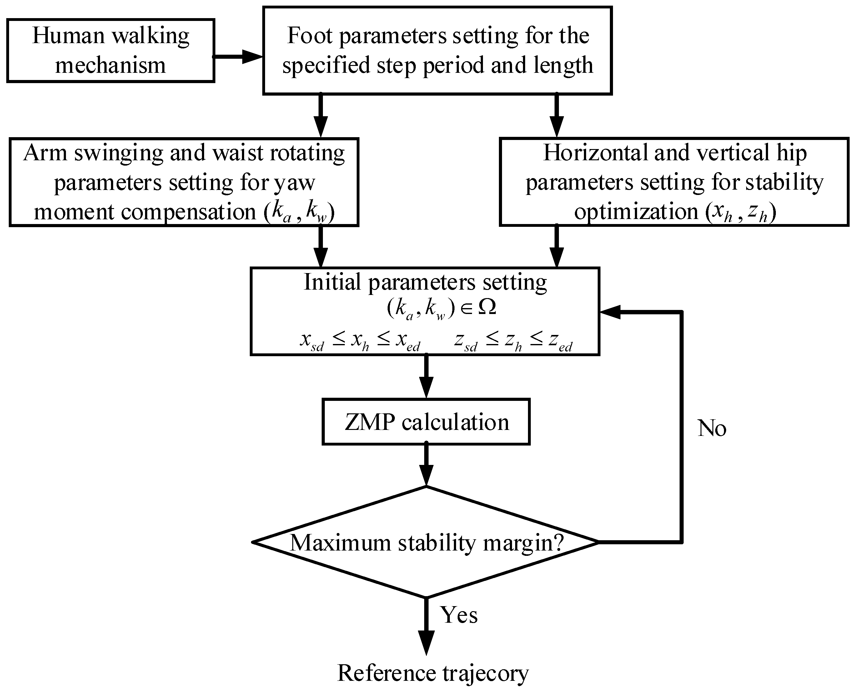
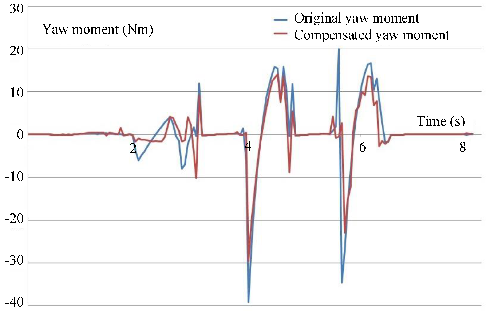
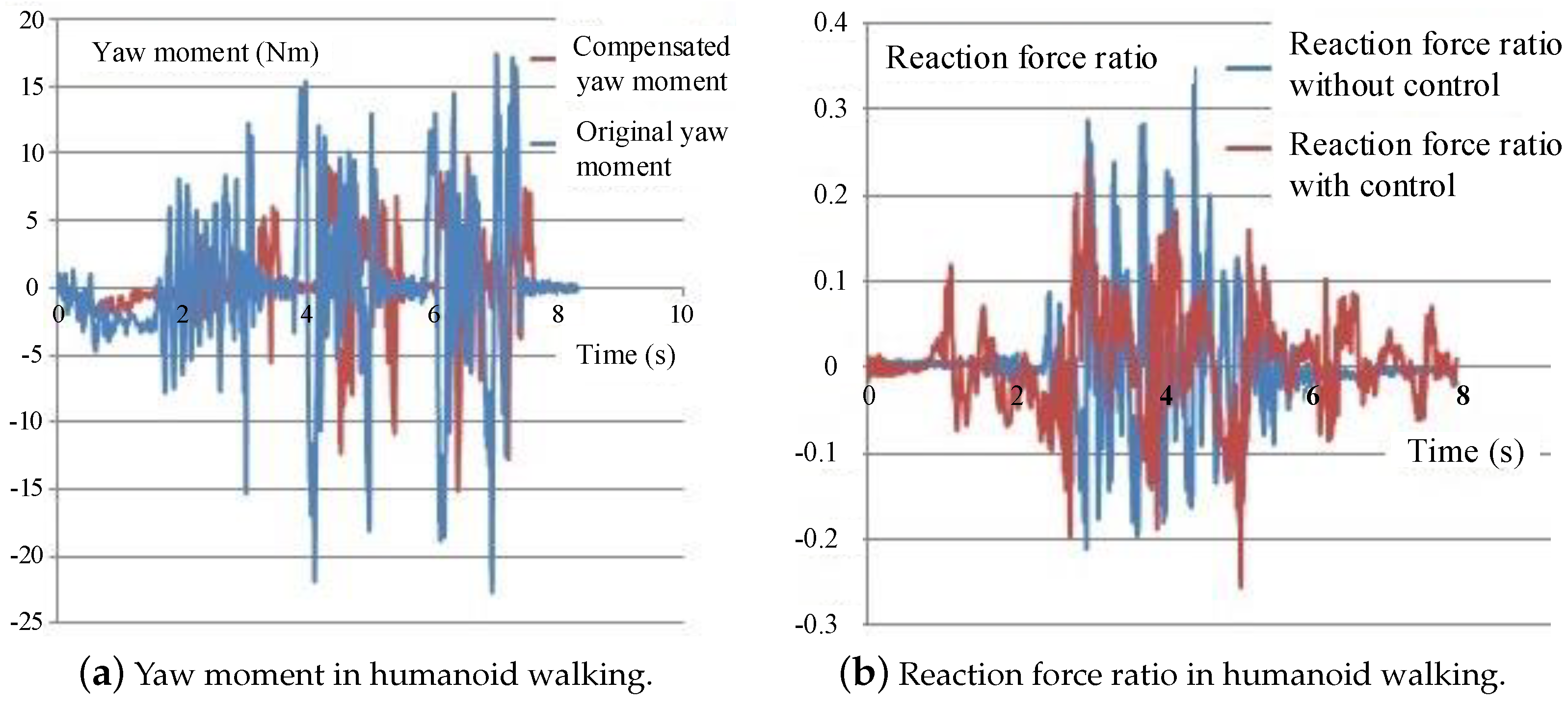
- A bionic walking pattern generator by mimicking the yaw moment compensation mechanism of humans is presented for rotational slip prevention. It effectively reduces the yaw moment with the optimized trajectories of swing arm and rotational waist based on the three mass model.
- (3)
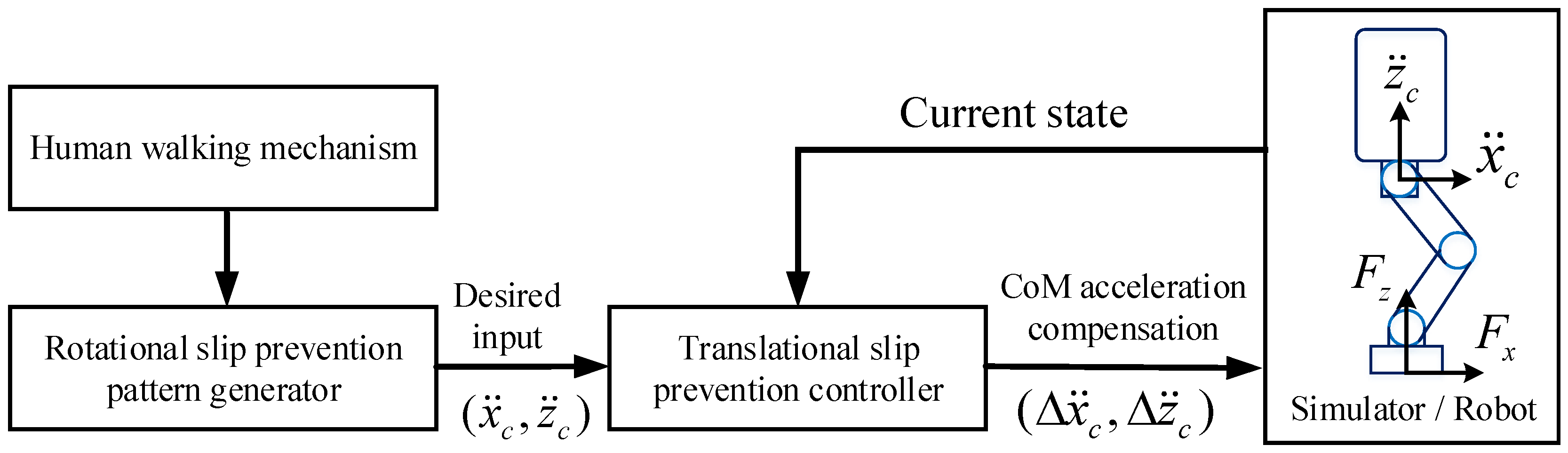
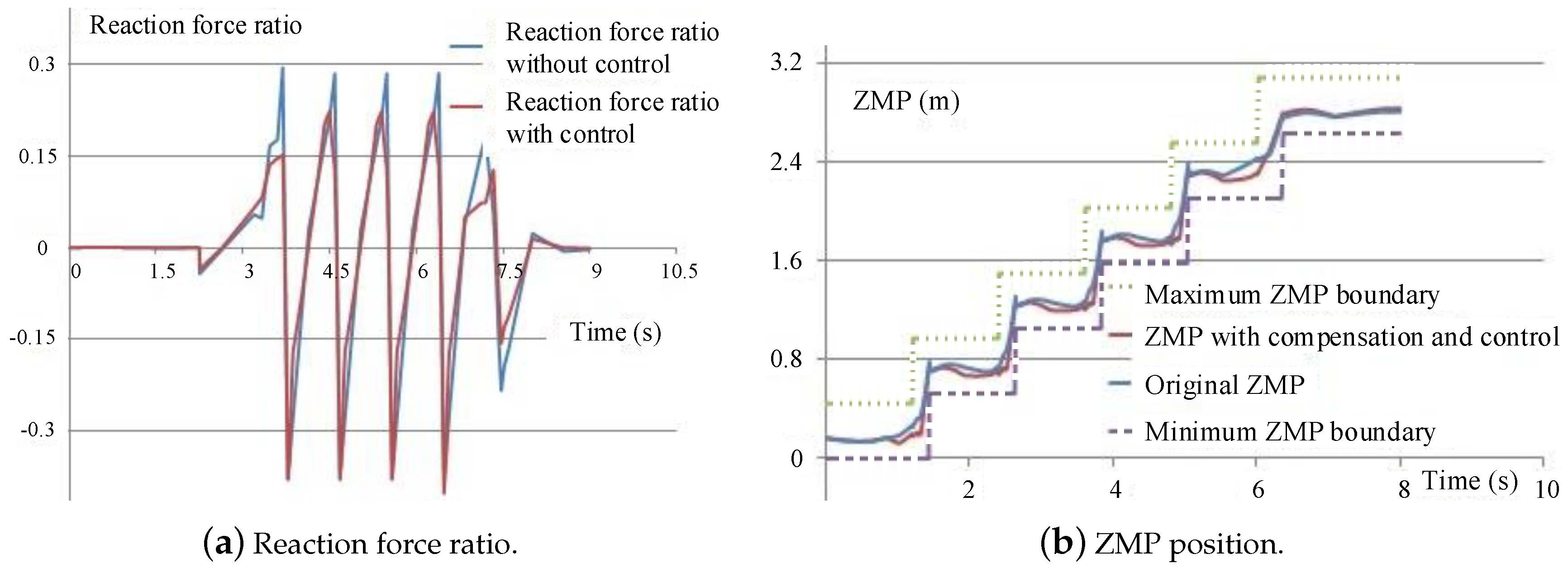
- A novel reaction force ratio reduction control using CoM (center of mass) acceleration compensation is proposed for translational slip prevention. It rapidly makes the ratio of tangential force to normal reaction force smaller than the coefficient of the ground friction.
2. Dynamics Model of Slip Prevention
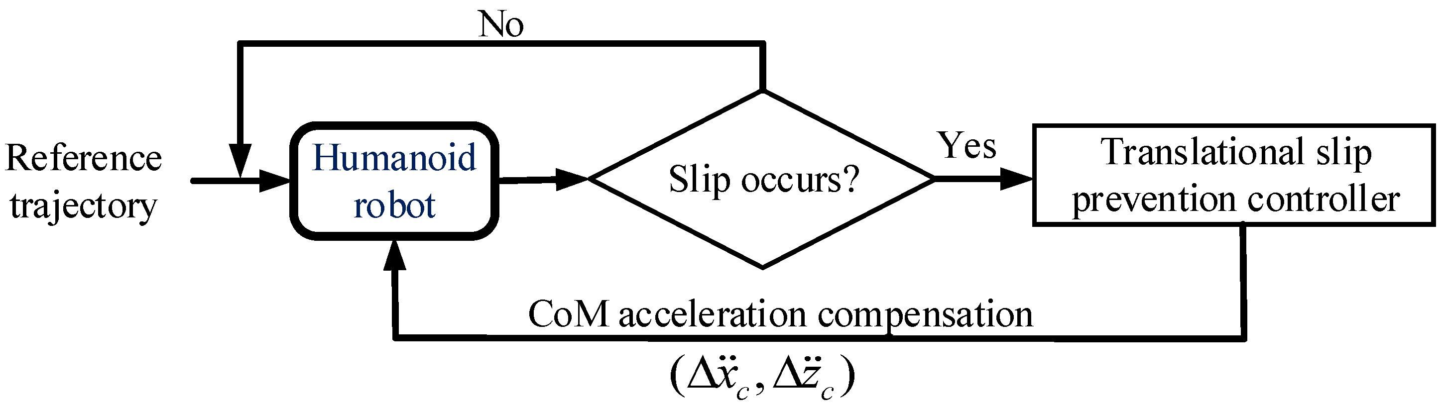
2.1. Slip Prevention Scheme Overview
2.2. The Three Mass Model
3. Rotational Slip Prevention
3.1. Yaw Moment Compensation Mechanism for Human Walking
- The arm swing and waist rotation in the vertical direction contribute to the yaw moment compensation in the walking.
- The arm swings in the back-and-forth pattern periodically, and the amplitude of the swing arm increases as the step length gets larger during the walking.
- The second derivative of the angle trajectory of the swing arm shows that the acceleration of the swing angle undergoes roughly the five stages: ascent, light fluctuation, descent, light fluctuation, and ascent.
- The waist rotation in the vertical direction occurs in the similar form as the periodic sinusoidal signal in human walking, and the rotation angle becomes larger when the walking speed increases.
3.2. Yaw Moment Compensation for Humanoid Robot Walking
3.3. Optimized Pattern Generation for Rotational Slip Prevention
4. Translational Slip Prevention
4.1. ZMP Deviation
4.2. Translational Slip Prevention Control
5. Simulations and Experiments
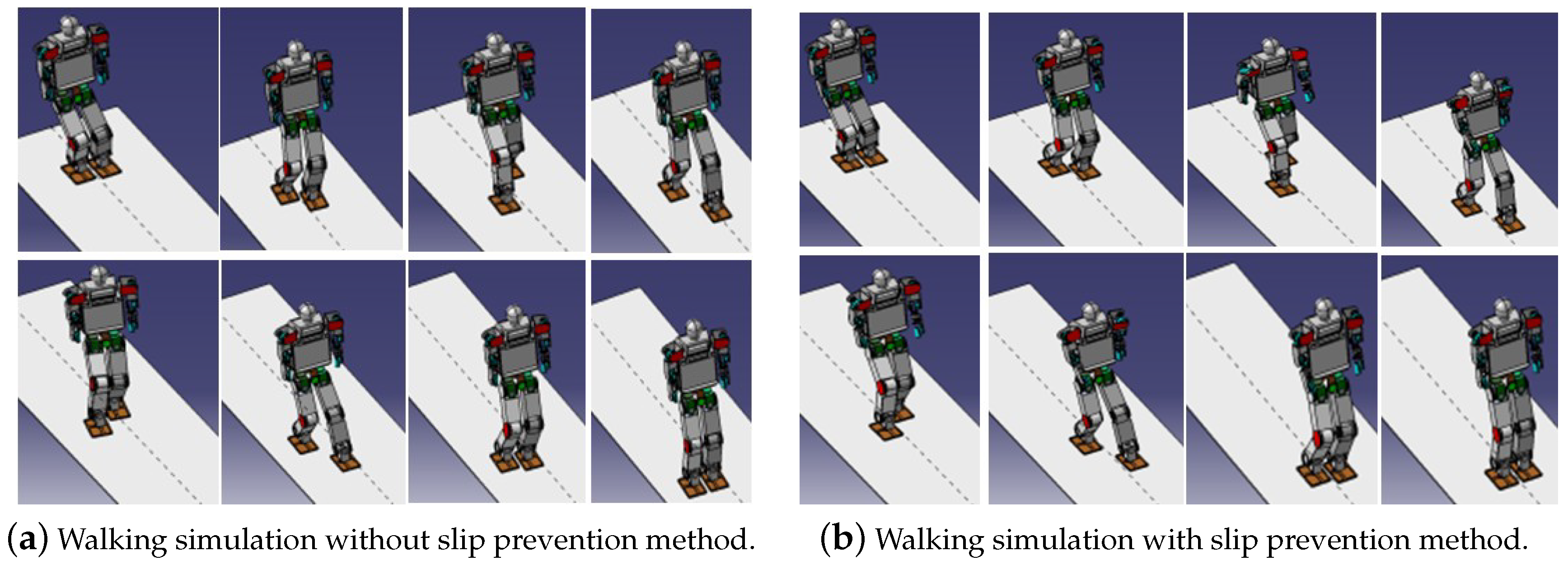
5.1. Simulations
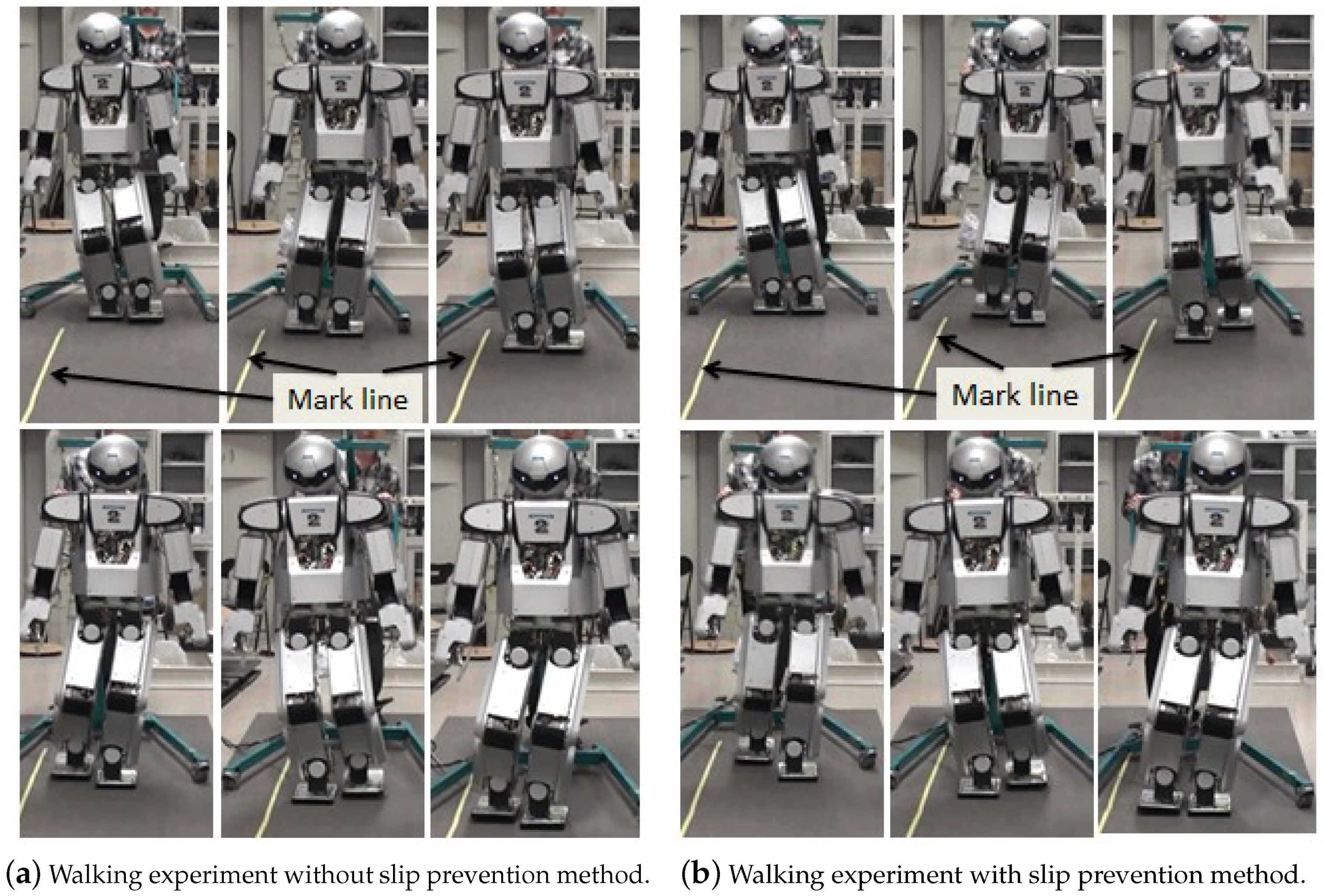
5.2. Experiments
6. Conclusions
Author Contributions
Funding
Conflicts of Interest
References
- Kuindersma, S.; Deits, R.; Fallon, M.; Valenzuela, A.; Dai, H.; Permenter, F.; Koolen, T.; Marion, P.; Tedrake, R. Optimization-based locomotion planning, estimation, and control design for the atlas humanoid robot. Auton. Robot. 2016, 40, 429–455. [Google Scholar] [CrossRef]
- Chen, X.; Yu, Z.; Zhang, W.; Zheng, Y.; Huang, Q.; Ming, A. Bioinspired Control of Walking With Toe-Off, Heel-Strike, and Disturbance Rejection for a Biped Robot. IEEE Trans. Ind. Electron. 2017, 64, 7962–7971. [Google Scholar] [CrossRef]
- Kajita, S.; Benallegue, M.; Cisneros, R.; Sakaguchi, T.; Nakaoka, S.I.; Morisawa, M.; Kaneko, K.; Kanehiro, F. Biped walking pattern generation based on spatially quantized dynamics. In Proceedings of the 2017 IEEE-RAS 17th International Conference on Humanoid Robotics (Humanoids), Birmingham, UK, 15–17 November 2017; pp. 599–605. [Google Scholar]
- Koolen, T.; Bertrand, S.; Thomas, G.; De Boer, T.; Wu, T.; Smith, J.; Englsberger, J.; Pratt, J. Design of a momentum-based control framework and application to the humanoid robot atlas. Int. J. Hum. Robot. 2016, 13, 1650007. [Google Scholar] [CrossRef]
- Ott, C.; Roa, M.A.; Schmidt, F.; Friedl, W.; Englsberger, J.; Burger, R.; Werner, A.; Dietrich, A.; Leidner, D.; Henze, B.; et al. Mechanisms and Design of DLR Humanoid Robots. In Humanoid Robotics: A Reference; Goswami, A., Vadakkepat, P., Eds.; Springer: New York, NY, USA, 2017; pp. 1–26. [Google Scholar]
- Yu, Z.; Huang, Q.; Ma, G.; Chen, X.; Zhang, W.; Li, J.; Gao, J. Design and development of the humanoid robot BHR-5. Adv. Mech. Eng. 2014, 6, 852937. [Google Scholar] [CrossRef]
- Yang, T.; Zhang, W.; Chen, X.; Yu, Z.; Meng, L.; Huang, Q. Turning Gait Planning Method for Humanoid Robots. Appl. Sci. 2018, 8, 1257. [Google Scholar] [CrossRef]
- Yu, Z.; Chen, X.; Huang, Q.; Zhang, W.; Meng, L.; Zhang, W.; Gao, J. Gait planning of omnidirectional walk on inclined ground for biped robots. IEEE Trans. Syst. Man Cybern. Syst. 2016, 46, 888–897. [Google Scholar] [CrossRef]
- Jiang, X.; Chen, X.; Yu, Z.; Zhang, W.; Meng, L.; Huang, Q. Motion Planning for Bipedal Robot to Perform Jump Maneuver. Appl. Sci. 2018, 8, 139. [Google Scholar] [CrossRef]
- Zhu, C.; Kawamura, A. What is the real frictional constraint in biped walking?—Discussion on frictional slip with rotation. In Proceedings of the 2006 IEEE/RSJ International Conference on Intelligent Robots and Systems, Beijing, China, 9–15 October 2006; pp. 5762–5768. [Google Scholar]
- Collins, S.H.; Adamczyk, P.G.; Kuo, A.D. Dynamic arm swinging in human walking. Proc. R. Soc. B-Biol. Sci. 2009, 276, 3679–3688. [Google Scholar] [CrossRef] [PubMed]
- Punt, M.; Bruijn, S.M.; Wittink, H.; Van Dieën, J.H. Effect of arm swing strategy on local dynamic stability of human gait. Gait Posture 2015, 41, 504–509. [Google Scholar] [CrossRef] [PubMed]
- Ugurlu, B.; Saglia, J.A.; Tsagarakis, N.G.; Caldwell, D.G. Yaw moment compensation for bipedal robots via intrinsic angular momentum constraint. Int. J. Hum. Robot. 2012, 9, 1250033. [Google Scholar] [CrossRef]
- Cisneros, R.; Yokoi, K.; Yoshida, E. Yaw moment compensation by using full body motion. In Proceedings of the 2014 IEEE International Conference on Mechatronics and Automation, Tianjin, China, 3–6 August 2014; pp. 119–125. [Google Scholar]
- Khadiv, M.; Moosavian, S.A.A.; Yousefi-Koma, A.; Sadedel, M.; Mansouri, S. Optimal gait planning for humanoids with 3D structure walking on slippery surfaces. Robotica 2017, 35, 569–587. [Google Scholar] [CrossRef]
- Brandao, M.; Hashimoto, K.; Santos-Victor, J.; Takanishi, A. Footstep Planning for Slippery and Slanted Terrain Using Human-Inspired Models. IEEE Trans. Robot. 2016, 32, 868–879. [Google Scholar] [CrossRef]
- Vázquez, J.A.; Velasco-Villa, M. Experimental estimation of slip in the supporting point of a biped robot. J. Appl. Res. Technol. 2013, 11, 348–359. [Google Scholar] [CrossRef]
- Hashlamon, I.; Gülhan, M.M.; Ayit, O.; Erbatur, K. A novel method for slip prediction of walking biped robots. Robotica 2017, 35, 766–786. [Google Scholar] [CrossRef]
- Takabayashi, Y.; Ishihara, K.; Yoshioka, M.; Liang, H.; Liu, C.; Zhu, C. Frictional constraints on the sole of a biped robot when slip. In Proceedings of the 2017 IEEE/RSJ International Conference on Intelligent Robots and Systems (IROS), Vancouver, BC, Canada, 24–28 September 2017; pp. 5011–5016. [Google Scholar]
- Bowyer, S.A.; Baena, F.R. Dynamic frictional constraints in translation and rotation. In Proceedings of the 2014 IEEE International Conference on Robotics and Automation (ICRA), Hong Kong, China, 31 May–7 June 2014; pp. 2685–2692. [Google Scholar]
- Li, J.; Huang, Q.; Yu, Z.; Chen, X.; Zhang, W.; Liu, H.; Gao, J.; Duo, Y. Integral acceleration generation for slip avoidance in a planar humanoid robot. IEEE/ASME. Trans. Mech. 2015, 20, 2924–2934. [Google Scholar] [CrossRef]
- Zhang, S.; Huang, Q.; Wang, H.; Xu, W.; Ma, G.; Liu, Y.; Yu, Z. The mechanism of yaw torque compensation in the human and motion design for humanoid robots. Int. J. Adv. Robot. Syst. 2013, 10, 57. [Google Scholar] [CrossRef]
- Huang, Q.; Yu, Z.; Zhang, W.; Duan, X.; Huang, Y.; Li, K. Generation of humanoid walking pattern based on human walking measurement. In Proceedings of the Humanoids 2008—8th IEEE-RAS International Conference on Humanoid Robots, Daejeon, Korea, 1–3 December 2008; pp. 99–104. [Google Scholar]
- Takenaka, T.; Matsumoto, T.; Yoshiike, T. Real time motion generation and control for biped robot-3rd report: Dynamics error compensation. In Proceedings of the 2009 IEEE/RSJ International Conference on Intelligent Robots and Systems, St. Louis, MO, USA, 10–15 October 2009; pp. 1594–1600. [Google Scholar]
- Kajita, S.; Hirukawa, H.; Harada, K.; Yokoi, K. Introduction to Humanoid Robotics; Siciliano, B., Khatib, O., Eds.; Springer: New York, NY, USA, 2014; pp. 69–79. [Google Scholar]


© 2018 by the authors. Licensee MDPI, Basel, Switzerland. This article is an open access article distributed under the terms and conditions of the Creative Commons Attribution (CC BY) license (http://creativecommons.org/licenses/by/4.0/).
Share and Cite
Zhou, Q.; Yu, Z.; Zhang, S.; Chen, X.; Qin, M.; Zhang, W.; Huang, Q. Simultaneous Prevention of Rotational and Translational Slip for a Humanoid Robot. Appl. Sci. 2018, 8, 1554. https://doi.org/10.3390/app8091554
Zhou Q, Yu Z, Zhang S, Chen X, Qin M, Zhang W, Huang Q. Simultaneous Prevention of Rotational and Translational Slip for a Humanoid Robot. Applied Sciences. 2018; 8(9):1554. https://doi.org/10.3390/app8091554
Chicago/Turabian StyleZhou, Qinqin, Zhangguo Yu, Si Zhang, Xuechao Chen, Mingyue Qin, Weimin Zhang, and Qiang Huang. 2018. "Simultaneous Prevention of Rotational and Translational Slip for a Humanoid Robot" Applied Sciences 8, no. 9: 1554. https://doi.org/10.3390/app8091554
APA StyleZhou, Q., Yu, Z., Zhang, S., Chen, X., Qin, M., Zhang, W., & Huang, Q. (2018). Simultaneous Prevention of Rotational and Translational Slip for a Humanoid Robot. Applied Sciences, 8(9), 1554. https://doi.org/10.3390/app8091554