1. Introduction
Human body communication (HBC) is a wireless communication method that uses the human body as part of the signal transmission medium, and it is expected to be among the technologies used in wireless body area networks [
1]. In the IEEE (Institute of Electrical and Electronics Engineers) 802.15.6 standard, HBC was adopted as one of the three physical layers for the body area network. The other two layers are narrowband and ultra-wide band [
2]. In comparison with other wireless communication technologies such as Bluetooth and Zigbee, HBC is advantageous in terms of its communication secrecy, low power consumption, and intuitive tactile operation. Because of these advantages, HBC is expected to be utilized in wearable devices for health care systems [
3]. There are two transmission mechanisms of HBC: galvanic and capacitive coupling [
4]. In galvanic HBC, the signal frequency is between 100 kHz and 10 MHz and the current flowing through the human body between the transmitter and the receiver contributes to the transmission [
5,
6]. In capacitive coupling, the signal frequency is between 100 kHz and 100 MHz and the current through the human body and the electric field around the human body contribute to the transmission [
7,
8,
9,
10]. Detailed studies on the electric field distribution and its contribution to capacitive coupling have been carried out using calculation methods such as the finite element method (FEM) and the finite-difference time-domain method (FDTD) [
11,
12].
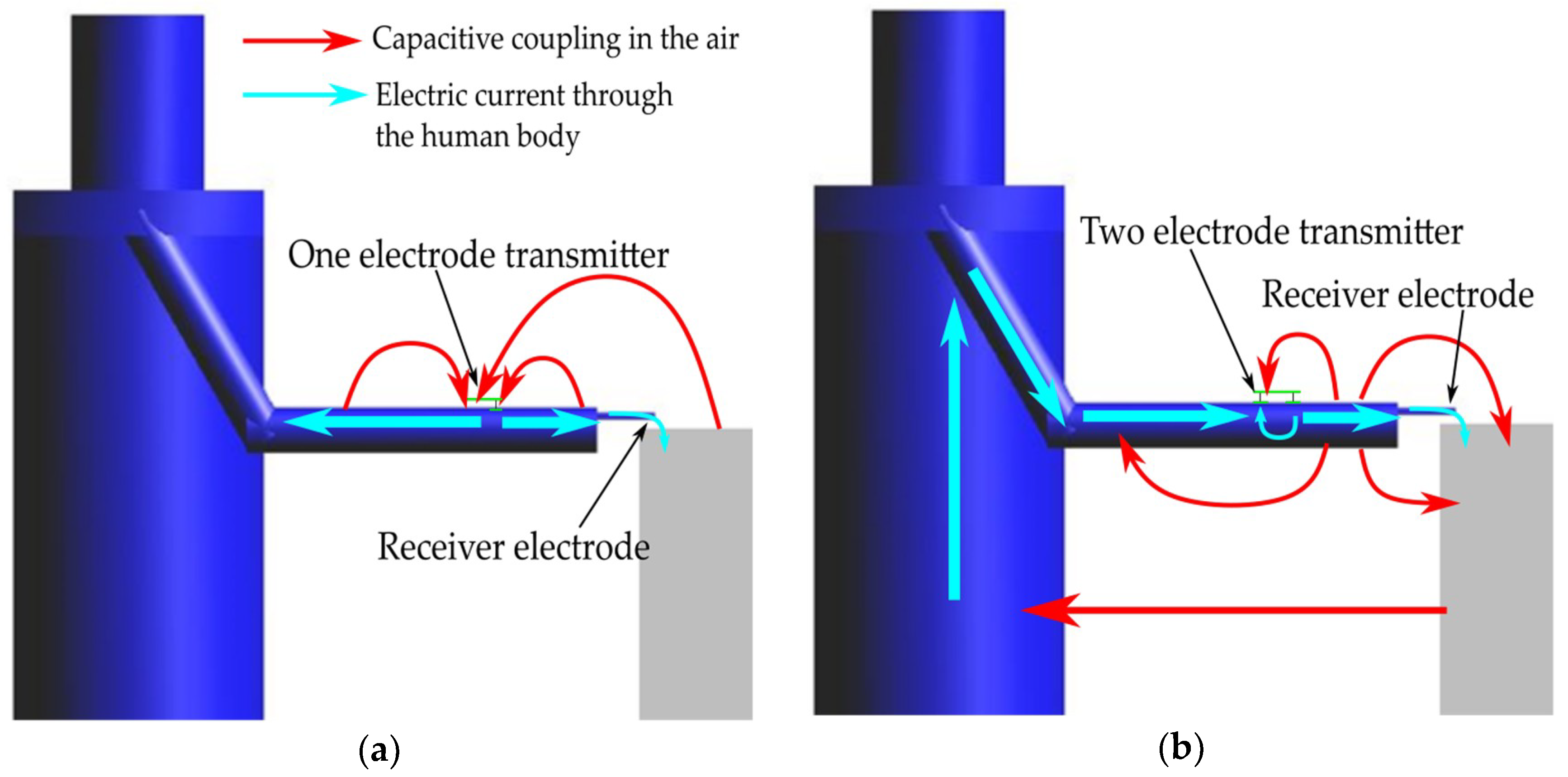
Although the conditions of the contact between the electrodes and the human body greatly influence the transmission characteristic of HBC, the electrode contact condition has not yet been standardized. The shape of HBC devices, and the electrode dimensions and arrangements, vary from study to study. In most HBC studies, researchers have adopted a one-electrode contact for both the transmitter and the receiver; the signal electrode is in contact with the human body while the ground electrode is left floating [
13,
14]. In recent years, some studies have used a two-electrode transmitter in which the signal and ground electrodes of the transmitter are both in contact with the human body. Some studies have compared the transmission characteristics and electric field distributions of one- and two-electrode contact transmitters [
15,
16,
17,
18,
19,
20]. Haga et al. conducted numerical simulation and investigated the difference between the received voltages and electric field distributions of one- and two-electrode transmitter models. They found that the received voltage and electric field were both enhanced by attaching the ground electrode to the human body [
17]. Hwang et al. investigated the effect of the ground electrode on the current distribution through numerical simulation. They found that attaching the ground electrode to the body increased the current from the signal electrode and altered the distribution of electric current in the human body [
19]. Fujii et al. numerically and experimentally analyzed the received signal levels using a one-electrode transmitter, a two-electrode transmitter, and a one-electrode receiver. A biological tissue-equivalent solid phantom was used in their experiments. In both the simulations and the experiments, the received signal was larger when the two-electrode transmitter was used [
20].
In these studies, the simulation models included only the human arm, and the influence of the torso and the environment surrounding the human body was not considered. In addition, only the strength of the electric field was investigated for the two types of electrode contact conditions. Kazim et al. reported a simulation-based study on the electrode configuration, transmitter/receiver placement on various human body postures, and susceptibility to physiological variations [
21]. Although this work provides a comprehensive understanding of HBC, the characteristics of the signal transmission path, including the direction of current flow and capacitive coupling by the electric field, have not been studied in detail. Therefore, the impact of the transmitter electrode contact condition on the signal transmission path and the transmission mechanism has been only partially clarified. Understanding the basic transmission mechanisms of HBC is important for developing design guidelines and applications of HBC.
In this study, the signal transmission paths of one- and two-electrode transmitters were investigated by numerical electromagnetic field analysis. The signal transmission characteristics and impedances in the signal paths were compared. Differences in the signal transmission paths were analyzed by comparing the electric field vector distributions and the electric currents in the human arm. The simulation results were assessed to explain why the received signal is larger when a two-electrode transmitter is used.
The remainder of this paper is organized as follows.
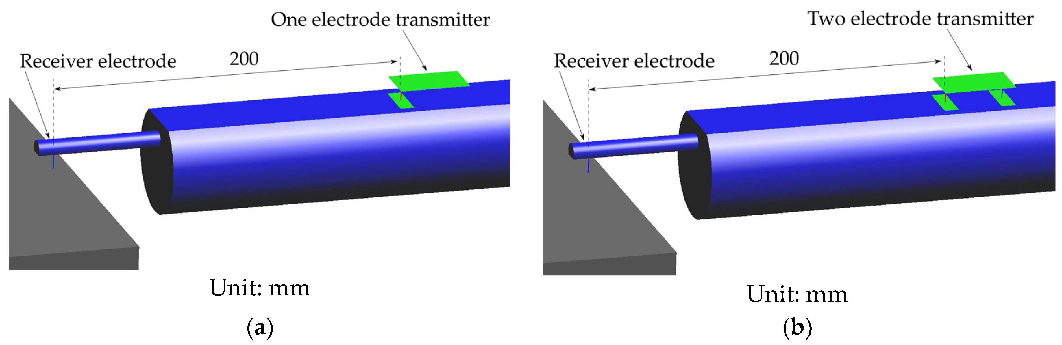
Section 2 describes the conditions and geometries of the simulation models of the human body, the two types of the transmitters, and the receiver.
Section 3 presents the results of electromagnetic field analysis, and
Section 4 discusses the differences between the signal transmission paths under the different contact conditions.
Section 5 provides the conclusions reached in this study.
3. Results
3.1. Transmission Characteristics and Impedance between the Transmitter Electrode
Table 1 gives the transmission characteristics of the one- and two-electrode transmitters. The transmission characteristics were evaluated by the ratio between the received signal amplitude and the amplitude of the transmitter output. The transmission characteristic of the two-electrode transmitter was 26 dB greater than that of the one-electrode transmitter.
Sensitivity of the electric properties in this simulation was evaluated by changing the values by ±12%. The relative permittivity εr was changed from 170 to 150 and 190, and the electrical conductivity σ was changed from 0.62 S/m to 0.55 S/m and 0.69 S/m. The transmission characteristics ranged from −50.5 dB to −50.0 dB for the one-electrode transmitter and −24.3 dB to −24.0 dB for the two-electrode transmitter. From these results, it was concluded that the sensitivity was sufficiently low for the present simulation.
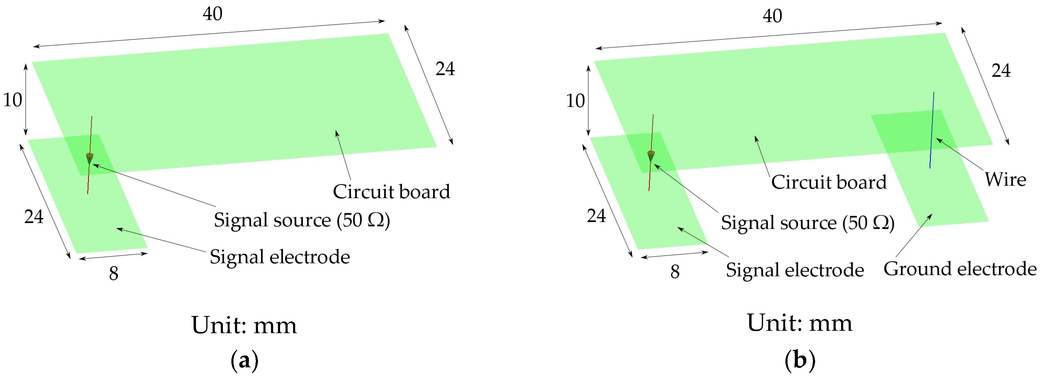
The impedance
Zin between the transmitter electrode and the ground electrode of the transmitter was calculated. In the case of the one-electrode transmitter, the circuit board was used as the ground electrode. The impedance
Zin is the total impedance of all external factors viewed from the output terminals of the signal source not including the resistance inside the transmitter.
Table 1 gives the calculated values of
Zin. The imaginary part of
Zin for the one-electrode transmitter was approximately 200 times larger than the real part. This is because the ground is floating in the one-electrode transmitter and the signal path contains capacitive couplings.
In contrast, the imaginary part of the Zin for the two-electrode transmitter was much smaller. This is because there is a direct signal path between the signal and ground electrodes that passes through the human body without capacitive coupling in the air. This result suggests that the electric passing through the human body contributes more to the signal transmission in the two-electrode transmitter than in the one-electrode transmitter. It should be noted, however, that the signal that reaches the receiver is only a small part of the total current that flows out of the transmitter electrode. Therefore, the electric field distribution around the transmitter and the receiver must be investigated to assess the total current.
3.2. Distribution of Electric Field
3.2.1. Electric Field Strength Distribution
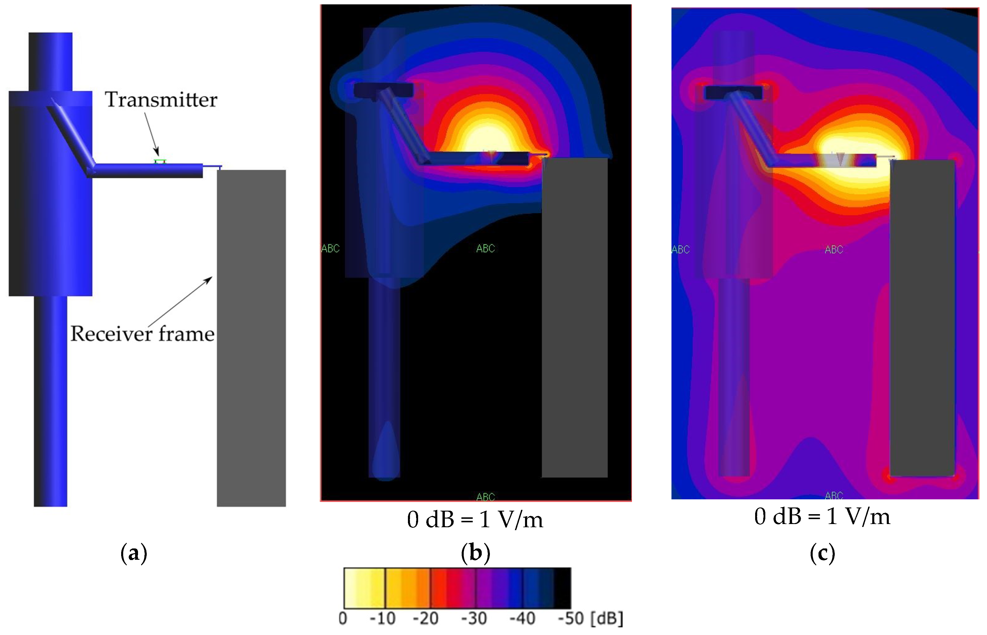
The distribution of the electric field around the arm is shown in
Figure 4. The plane shown in
Figure 4 is a vertical cross-section that passes through the feed point of the transmitter viewed from the right side of the human body model.
Figure 4b shows the electric field distribution of the one-electrode transmitter. The electric field is distributed mainly above right arm in this case. In the case of the two-electrode transmitter, a strong electric field of −20 to −10 dB was distributed around the transmitter, inside the arm, and below the arm, as shown in
Figure 4c.
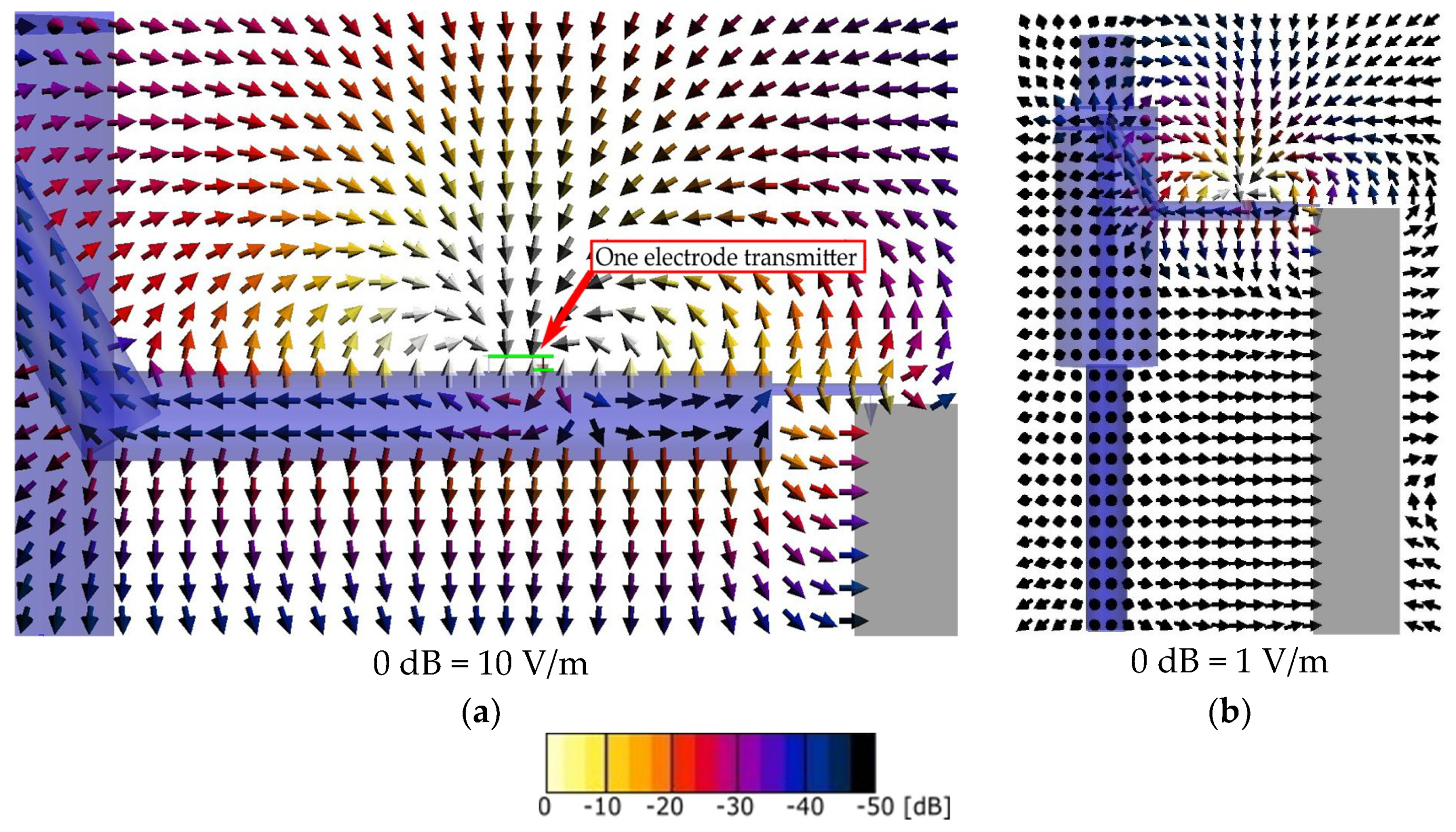
3.2.2. Electric Field Vector Distribution
Figure 5 shows the vector distribution of the electric field when the one-electrode transmitter was used. The plane shown in
Figure 5a,b is a vertical cross-section passing through the feed point of the transmitter as viewed from the right side of the human body model. This distribution was obtained when the maximum received voltage was recorded. The direction of each arrow represents the vector of the electric field at that point, and the color of the arrows and stream lines represents the strength of the electric field.
Figure 5a shows that the electric field in the one-electrode case travels from the surface of the arm through the space around the arm to the circuit board and is distributed symmetrically around the transmitter.
Figure 5b shows a wider view of the same distribution as in
Figure 5a, including the human body and the receiver. The electric field excited in the human body and under the arm was weaker than that above the arm. The signal path was concentrated locally in the space above the arm because the only return path is through the capacitive coupling of the floating ground.
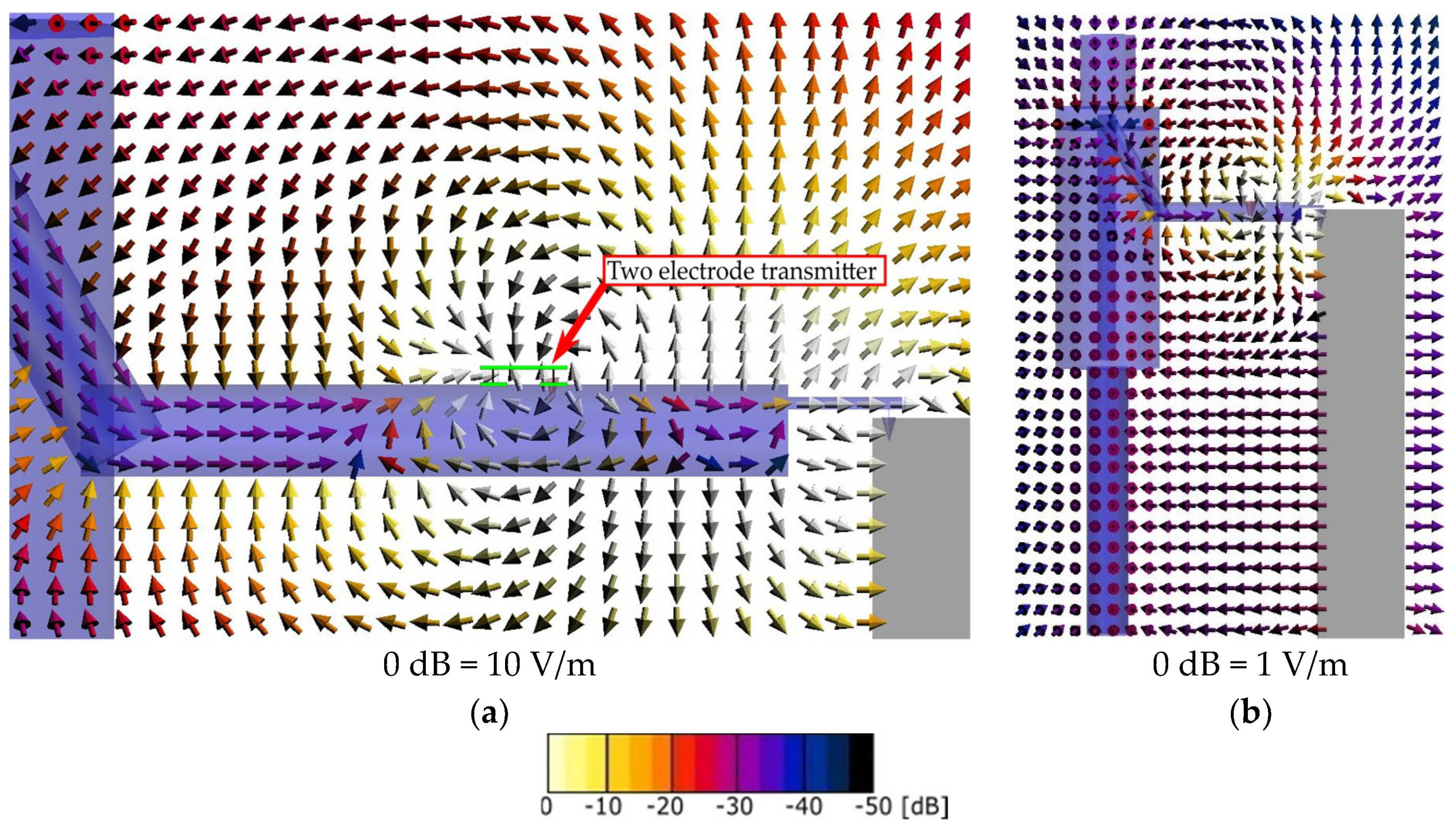
Figure 6 shows the vector distribution of the electric field when the two-electrode transmitter was used. A strong electric field was distributed in the space above and below the arm, as shown in
Figure 6a. In the space above the arm, the electric field traveled in two directions; coupling occurred from the arm to the circuit board of the transmitter and from the arm to the surface of the receiver frame. In the space below the arm, the electric field from the surface of the arm was directed to the upper arm and the surface of the receiver frame. In the case of the two-electrode transmitter, both the electrical current inside the arm and the capacitive coupling via the air contributed to signal transmission. The distribution in a wider area is shown in
Figure 6b. This figure shows that there was a relatively strong electric field distribution between the surface of the receiver frame and the torso. This electric field represents the capacitive coupling between the human body and the receiver frame.
In order to evaluate the influences of realistic objects such as clothes, torso and legs were covered with sheet that had relative permittivity εr of 3 and electric conductivity σ of 0 S/m, and thickness of 5 to 10 mm. The electric properties are the same as that of polyester. There were no noticeable differences in the direction and strength of the electric field, and the received signal amplitudes.
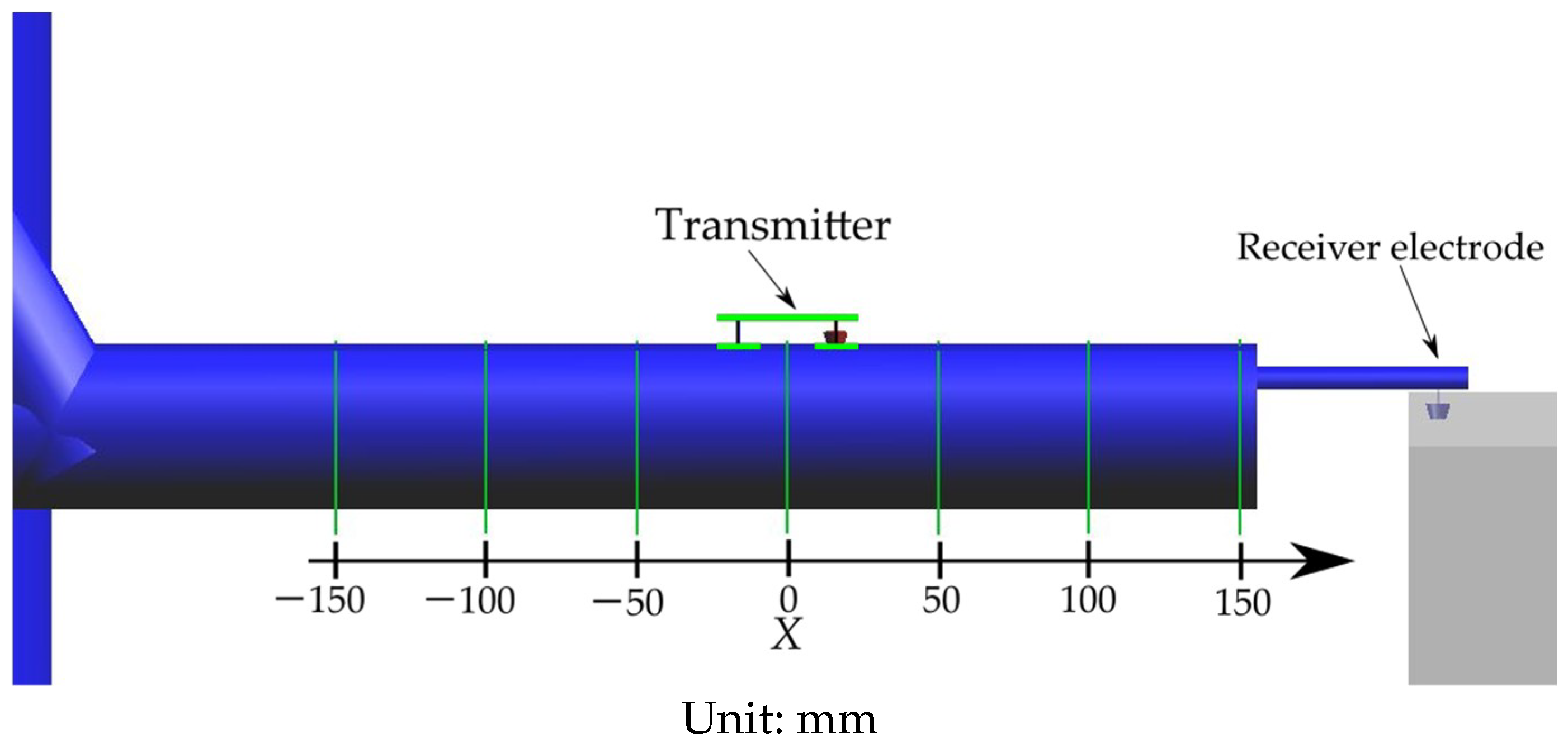
3.3. Electric Current in the Arm
The amount of electric current passing through cross-sections along the arm was then evaluated.
Figure 7 shows the locations of the analyzed cross-sections. The cross-sections were set at 50 mm intervals from the center of the transmitter circuit board (X = 0 mm) with distances toward and away from the body represented by negative and positive X, respectively. The current that flowed in the X-direction and the current
IR that flowed into the receiver resistor were recorded, at the time of the maximum received voltage.
Table 2 gives the amount of electric current flowing through the arm in the when one- and two-electrode transmitters cases. When the one-electrode transmitter was used, the electric current was positive for positive X negative for negative X. This means that the current on the positive X side of the transmitter flowed from the transmitter to the finger and that on the negative X side flowed in the opposite direction. The magnitude of the current passing through the cross-sections of the arm decreased as the distance from the transmitter increased. The current that flowed into the resistor of the receiver was 1.50 μA.
When the two-electrode transmitter was used, the current flowed in the same direction, from the elbow to the finger, for both positive and negative X. A large negative current flowed just beneath the transmitter. This means that a large amount of current flowed directly from the signal electrode to the ground electrode through the human body. The magnitude of the current passing through the cross-sections decreased as the distance from the transmitter increased. The current that flowed into the receiver resistor was 31.2 μA.
3.4. Comparison with Experimentally Measured Values
Received signal was measured experimentally to compare with the simulation results. The transmitter was powered by a small battery (CR2032) and the circuit board and the electrodes had the same dimensions used in the simulation. The frequency was 10 MHz and the output signal amplitude was 744 mV. The receiver consisted of a preamplifier and a battery-powered oscilloscope to measure the output of the preamplifier. The preamplifier and the oscilloscope were placed on a tall box that had the same dimensions as the receiver frame in the simulation. The surface of the box was covered with aluminum foil, which was connected to the ground of the receiver circuit. Although it is often mentioned in the literatures that the measuring apparatuses affected the capacitive coupling in HBC, we assumed that the battery-powered oscilloscope acted as part of the receiver ground and had little effect on the overall signal path in this case. Received signal was measured for five times by a single subject. The results are given in
Table 3. The transmission characteristic was evaluated by the ratio between the amplitudes of the received signal and the transmitter output. The difference between the one- and two-electrode transmitters was 18.3 dB for the experiment and 26.3 dB for the simulation. It was concluded that these similarities verified the reliability of the simulation.
4. Discussion
The above analysis of the electric field strength distribution and current flow revealed the differences between the signal transmission behaviors of the one- and two-electrode transmitters. The results are qualitatively summarized in
Figure 8a,b. In the case of the one-electrode transmitter, the electric field spread from the transmitter to the space above the arm and not inside the arm. In the case of the two-electrode transmitter, the electric field was distributed above and below the arm and penetrated the arm. Furthermore, when the two-electrode transmitter was used, the electric field was distributed more intensely between the receiver frame and the torso than when the one-electrode transmitter was used.
Furthermore, in the one- and two-electrode transmitter cases, the current flowed in opposite directions in part of the human forearm between the transmitter and the elbow. This means that the only return path of the one-electrode transmitter is through the capacitive coupling of the floating ground of the transmitter. In contrast, in the case of the two-electrode transmitter, current flowed from the torso, through the upper arm, and to the ground electrode of the transmitter that was in contact with the arm. The capacitive coupling between the receiver ground (i.e., the receiver frame) and the torso and lower parts of the human body allowed the current to flow from the receiver ground to the torso. The capacitive coupling between the receiver ground and the underside of the arm also contributed to the return path. In effect, the area of the ground electrode of the transmitter was enlarged by putting the ground electrode of the transmitter in contact with the human body. It was concluded that this increased coupling is the mechanism producing the larger received signal when the two-electrode transmitter was used.
The signal transmission path and mechanism of HBC revealed in this study are not readily apparent from the distributions of electric field strength that are often reported in previous studies. The method used in this study to analyze the difference between the one- and two-electrode transmitters can be used to analyze other HBC configurations. The results will be useful for the development of HBC applications in terms of device placements and practical choice of electrode configurations.
5. Conclusions
Signal transmission path of human body communication from a wearable transmitter worn on the wrist to an off-body stationary receiver touched by the user’s finger was investigated. Numerical simulation results of electric field strength distribution, electric field vector distribution, and electric current in the human body were compared for one-electrode transmitter and two-electrode transmitter. When the signal and ground electrodes of the transmitter were in contact with the human arm, i.e., the two-electrode transmitter, capacitive coupling between the receiver ground and the human torso was much stronger than that of the one-electrode transmitter. As a result, there was electric current flow inside the torso, upper arm, elbow, and to the ground electrode of the transmitter. The increased capacitive coupling and the current flow inside the human body contributed to stronger return path. In the case of one-electrode transmitter, the only return path was through the capacitive coupling of the floating ground. This difference in the transmission path explains why the received signal was larger when two-electrode transmitter was used. Transmission path analysis in this study contributes to the better understanding of signal transmission mechanism of HBC and will be useful for developing HBC applications.


 and
and 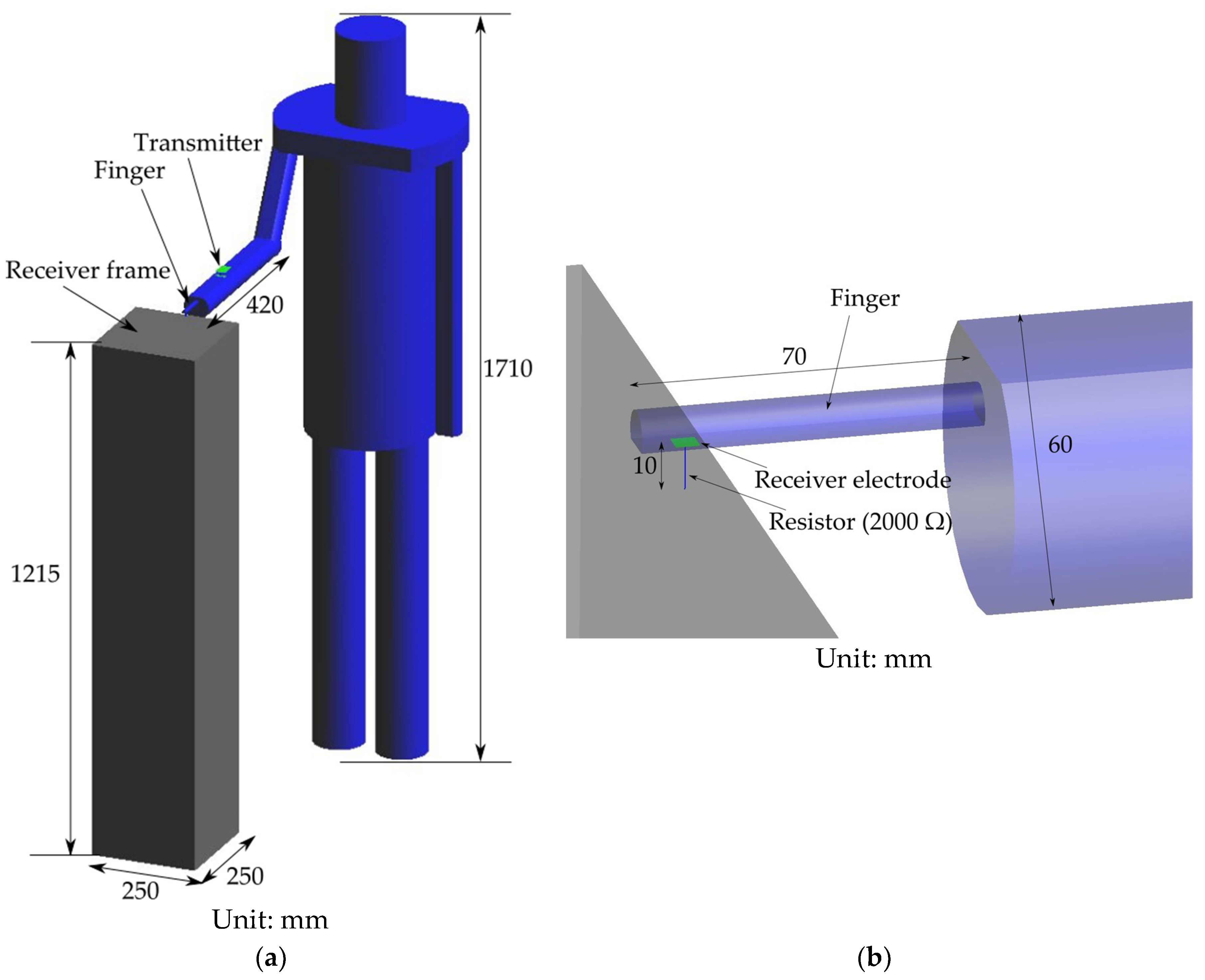


