Article

Response Prediction and Monitoring Feasibility of a Stow Net System Using Measured Environmental Data in the Southwest Coast of Korea

Department of Ocean Engineering, Texas A&M University, Haynes Engineering Building, 727 Ross Street, College Station, TX 77843, USA
*
Author to whom correspondence should be addressed.
These authors contributed equally to this work.
Appl. Sci. 2018, 8(9), 1517; https://doi.org/10.3390/app8091517
Submission received: 29 July 2018 / Revised: 27 August 2018 / Accepted: 28 August 2018 / Published: 1 September 2018
(This article belongs to the Special Issue Fishery Acoustics, Applied Sciences and Practical Applications)

Abstract

:
This paper investigates the response characteristics of a stow net under wave and current excitations, as well as the feasibility of its monitoring system to check net functionality and prevent loss of fishing gears. The stow-net model is based on one of existing types used in southwest coast of South Korea. The measured wave and current data there are acquired and inputted as environmental loads for numerical simulations. The Morison equation for a moving object with equivalent net model is utilized as the external-force estimator, which has been validated by many researchers regarding fish-cage studies. Since the modelling of all the net elements is inefficient in terms of computational time in time-domain simulations, cruder equivalent-drag net elements are devised with equivalent wet mass, projected area, and axial stiffness. The performance of stow net is highly influenced by current velocity. Stow nets submerge more in stronger currents, which results in less wave forces. The proposed monitoring system can provide useful information, such as net functionality and loss of stow net, using the minimum number of monitoring sensors.

1. Introduction

Recently, marine-environmental pollution caused by marine litter has increased. In particular, the marine-environmental pollution caused by the loss of fishing gear is recognized as a serious problem [1]. In South Korea, 20% of used fishing gears are lost or abandoned, and only approximately 15% of the lost or abandoned fishing gears are collected—therefore, the remaining 85% may harm the marine ecosystem [2]. To prevent the loss of fishing gear, it is necessary to better understand the dynamics and behaviors in waves and currents, and develop an efficient way to monitor them.
The predominant type of fishing gear in South Korea is the drift gill net, stow net, and fish trap. Among them, the stow net has traditionally been utilized on the southwest coast of South Korea by using strong tidal current [3,4]. The stow net freely changes its direction according to the direction of current flow by a single-point-mooring line (SPM) fixed with anchor, and the current force leads to the catch of fish. In order to realize such characteristics, the density of its net entrance should be smaller than that of water. As the stow net influenced by strong current and wave excitations, the possibility of net-loss increases a lot through braking of lines or twisting of net assembly.
In this regard, reliable numerical tools for the global-performance evaluation of stow nets for diverse ocean environmental conditions are needed. Cage-mooring-coupled-dynamics numerical tools have been developed by several researchers using the Morison-force and screen models. When the inflow angle is less than 45°, the Morison-force model provided good validation results against measurements even without considering interactions between twines [5]. Lee, et al. [6] suggested a mathematical model to analyze fishing cage system in current and wave including comparisons with experimental results. Huang, et al. [7] investigated the effects of waves and currents on gravity-type cages and mainly focused on mooring tensions and volume reduction coefficients of the cage. In addition, Huang and Pan [8] conducted a fatigue analysis of a SPM-cage system under wave and current loads. Zhao, et al. [9] investigated hydrodynamic behaviors of gravity cages in currents and waves including comparisons with experimental results. Zhao, et al. [10] studied dynamic behaviors of box and column-shaped net cages in waves and currents. Cifuentes and Kim [11] conducted numerical simulations of a fishing net in currents, and a wake model was applied to downstream nets. In addition, Cifuentes and Kim [12] further investigated dynamic behaviors of fishing nets under wave and current excitations. Cifuentes and Kim [13] also investigated the coupled dynamics of a complex system including SPM-buoy-feeder-cage. Chen and Christensen [14] also solved hydrodynamic responses of a floater-net system in currents and waves.
The purpose of this study is to predict dynamic behaviors of stow nets for various ocean conditions by using time-domain computer simulations and assess the feasibility of the corresponding monitoring system. Sensors can measure buoy motions and mooring/rope tensions. Traditionally, the performance analysis of stow nets was checked by test operations or small-scale experiments [15,16,17,18,19,20]. Through numerical simulations, more physical insights for better design and operation are available. Furthermore, with the accumulated data by numerical simulations, it can indirectly be used for checking net performance.

2. Numerical Model

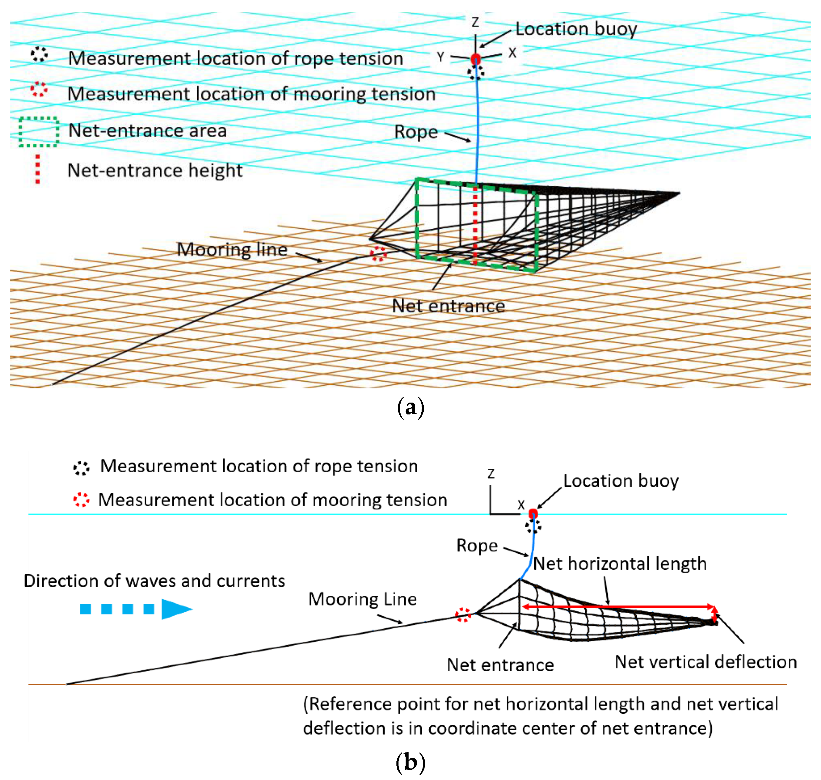
2.1. Configuration of Stow Net

Figure 1 shows 2D and 3D views of the stow-net model. Material properties and design parameters of the stow net are summarized in Table 1. The stow-net model is selected from one of the actual designs used in southwest coast of South Korea. The stow net consists of a net assembly, a location buoy, a rope, and mooring lines. The net assembly is made up of a net, a head rope, a ground rope, buoys, and weights in detail. The height and width of the net entrance and length of the net assembly are 15 m, 30 m, and 60 m, respectively. The net is made of polyethylene, and small weights are installed between threads to adjust the buoyancy to weight ratio (BWR) of the net to 1.01. Head and ground ropes, which are made of oak, are installed on top and bottom of the net entrance. One of the most important parameters to determine net-stretching performance is the BWR of the net entrance, and in this study, the BWR of the net entrance is fixed to be 1.5. Buoys are placed at both ends of the head rope to create additional buoyancy while weights are located at both ends of the ground rope to adjust the BWR of the net entrance. Polypropylene is used for mooring lines and the rope. Especially, a SPM is used for the station keeping purpose with heavy anchor at a target location. In this case, the end point of SPM is assumed to be fixed. A rope is used to connect the location buoy and the net assembly. The location buoy is installed to show the location of the stow net visually. Moreover, the primary goal of this research is to develop monitoring system for the stow net to extensively, continuously monitor essential parameters in real time so that fishers can estimate net functionality through entrance area and monitor whether fishing gear is lost. Monitoring sensors are positioned at the mooring line #1 to measure tension and location buoy to measure translational motion and rope tension. Measured data will be wirelessly transferred to a fishing boat. With the pre-assessed data base, for instance, by reading the mean mooring tension and surge mean offset of location buoy, current velocity can roughly be predicted. Then, using the relation between net entrance area and current velocity (e.g., Figure 6), the functionality of the net can indirectly be assessed. Sudden decrease of mooring or rope tension close to zero means that they are disconnected.

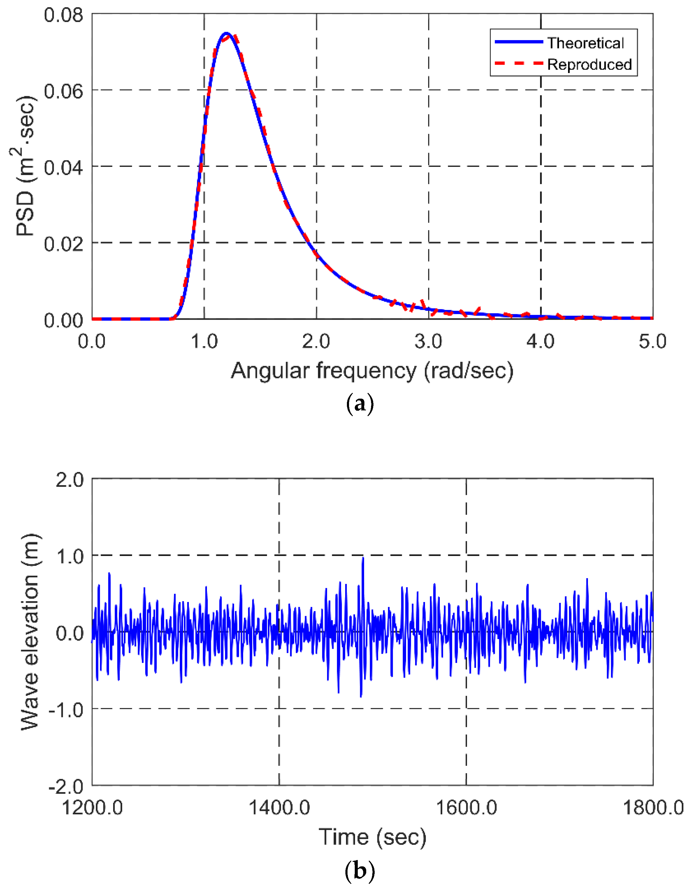
2.2. Time-Domain Numerical Simulation

The numerical model of the stow net is designed by using a commercial software, OrcaFlex. This software is able to perform fully coupled analysis of floaters and line elements with consideration of nonlinear effects [21]. The net, rope, and mooring line are modelled by line and 3D buoy models. The line model is comprised of a series of nodes and segments. In the node, weight, buoyancy, drag, and properties related to force are lumped, and stiffness properties, i.e., axial, bending, and torsional stiffness, are modelled in the massless segment. The 3D buoy model is utilized for not only the connection of two or three lines considered as the dummy, rigid body causing negligible influences on entire dynamics but also the location buoy, weight, and other buoys. The equation of motion for the entire model can be describe as Equation (1):
M ( p , a ) + C ( p , v ) + K ( p ) = F ( p , v , t )
where M(p,a) is the inertia force matrix, C(p,v) is the damping force matrix, K(p) is the stiffness force matrix, and F(p,v,t) is the external force vector that is hydrodynamic force in this study. The symbols p, v, a, and t represent position, velocity, acceleration, and time, respectively. The hydrodynamic force from current and wave is calculated by the Morison equation for a moving object. The Morison equation is made up of linear inertia force and nonlinear drag force. In case of a cylindrical object, hydrodynamic force per unit length can be expressed as follows:
F W = C m ρ π D 2 4 u ˙ C a ρ π D 2 4 a + 1 2 ρ C d D | u v | ( u v )
where Cm(= 1 + Ca), Ca, and Cd represent the inertia, added mass, and drag coefficients. D and ρ denote an outer diameter of a cylinder and density of seawater. u ˙ and u are acceleration and velocity of fluid particles. Ca is fixed to be 1 for the entire stow net [22]. In addition, Cd of the net is chosen by the formulation suggested by DeCew, et al. [23]. The formulation is revised from Choc and Casarella [24] with expanded Reynold number up to 107, which is given in Equation (3):
C d = ( 8 π , Re n s ( 1 0.87 s 2 ) , 0 < Re n < 1 1.45 + 8.55 Re n 0.9 , 1 < Re n 30 1.1 + 4 Re n 0.5 , 30 < Re n 2.33 × 10 5 3.41 × 10 6 ( Re n 5.78 × 10 5 ) , 2.33 × 10 5 < Re n 4.92 × 10 5 0.401 ( 1 e Re n / 5.99 × 10 5 ) , 4.92 × 10 5 < Re n 10 7 s = 0.077215665 + ln ( 8 / Re n ) ) ,
where Ren (= ρVnD/μ) is Reynold number, and Vn denotes relative velocity between the fluid particle and the object acting on the normal direction. In case of mooring lines and ropes, Cd is fixed to be 1.2 [25].
Developing a numerically equivalent net model is required since it is unfeasible to make actual net model with a large number of threads. The entire procedures are well described in authors’ previous publications (e.g., Cifuentes and Kim [11]), and their numerical results have been well matched against various experimental results. The equivalent net model should be generated so that wet mass, projected area, and axial stiffness have to be equivalent between the actual physical net and numerical net. In this case, wet mass is adjusted by adjusting mass of 3D buoy installed between threads in the net setting the BWR of the net to be 1.01. The projected area is matched based on the solidity ratio that is defined as a ratio of total area of threads to the projected area perpendicular to wave and current directions, and solidity ratio is fixed to be 0.1 here. The axial stiffness of the equivalent net is adjusted by modified Young’s Modulus, as described in Fredheim [26].
Time histories of random waves are generated by superposing 100 regular-wave components with randomly perturbed frequency interval. The following JONSWAP wave spectrum, which is given in Equation (4), is used to generate long-crested random waves.
S J ( ω ) = ( 1 0.287 ln ( γ ) ) 5 16 H s 2 ω p 4 ω 5 exp ( 5 4 ( ω ω p ) 4 ) γ exp ( 0.5 ( ω ω p σ ω p ) 2 ) σ = 0.07 ω ω p σ = 0.09 ω > ω p
where ω is wave angular frequency (rad/s), ωp (= 2π/Tp) is peak angular frequency (rad/s), Tp is peak period (s), Hs is significant wave height (m), and γ is the enhancement parameter. Wheeler stretching method is further applied to Airy wave theory to represent wave kinematics more realistically above mean waver level [27,28]. Current profile is generated by using the power-law method, which is defined as follows:
V c ( z ) , = V c b + [ ( V c f V c b ) z z b z f z b ] 1 / p o ,
where Vcf and Vcb are current velocities at free surface and seafloor, respectively. zf and zb denote vertical coordinates of still water level and seafloor, respectively. po is the power law exponent. In this paper, waves and currents are linearly superposed, and the nonlinear interactions between them are not considered.

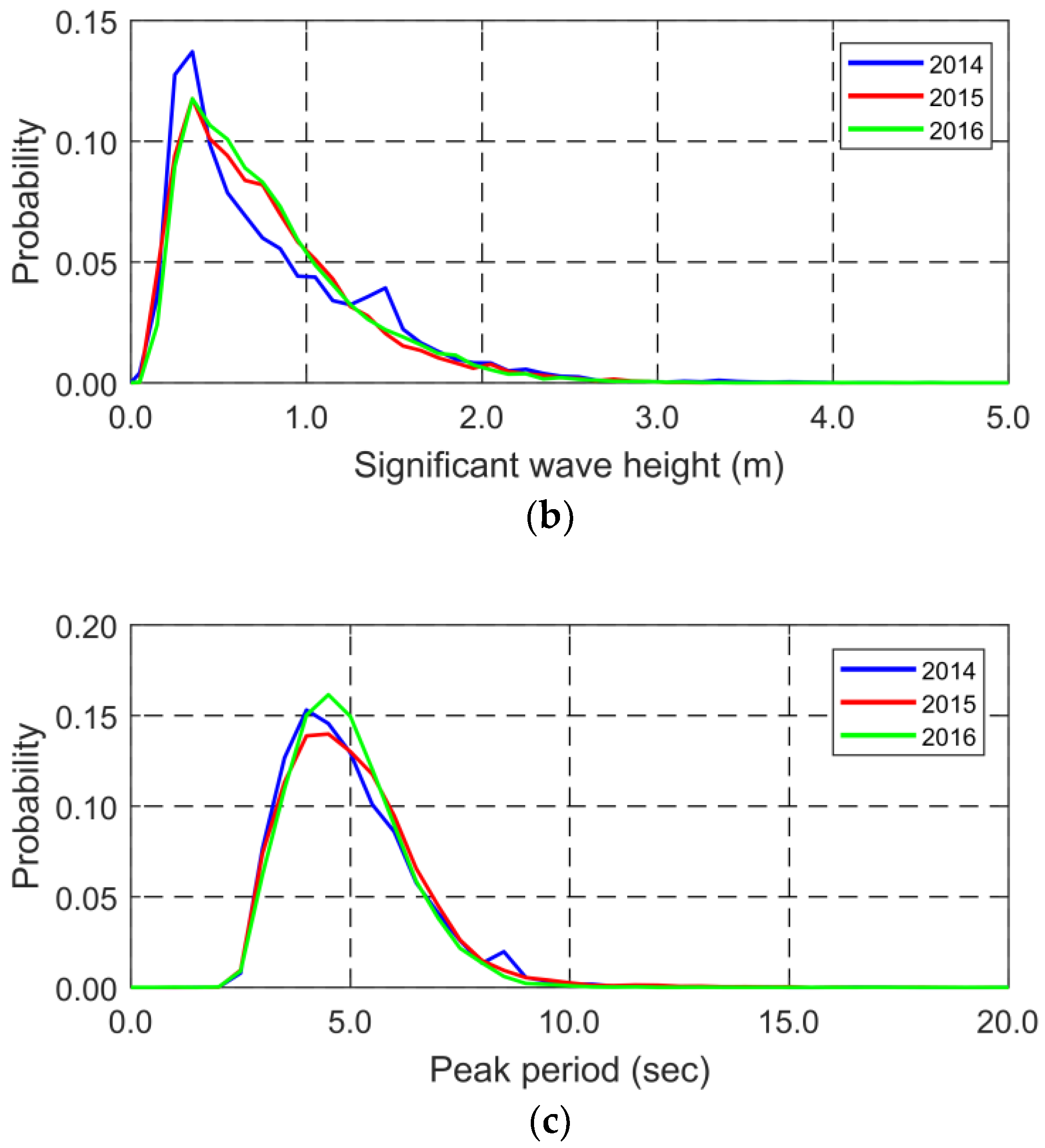
2.3. Environmental Conditions

Table 2 provides environmental conditions simulated in this study. Wave and current conditions are selected based on the real measurement data observed in southwest coast of South Korea for 2014–2016 as represented in Figure 2. Furthermore, fishing conditions for different wave heights are suggested in a guide [29]. According to the guide, fishing is prohibited when the wave height is higher than 5 m. From the guide and real measurement data, wave heights for analyses were determined. Current velocity at free surface is from 0.25 m/s to 1.5 m/s assuming that current velocity at bottom is 20% of current velocity at free surface. Wave and current directions are assumed to be perpendicular to the net entrance, i.e., collinear environments and net. Simulation time is 30 min for each case. Figure 3 provides an example case of generated time histories of sea surface from JONSWAP wave spectrum at significant wave height of 1.0 m, and the comparison of the corresponding input and regenerated wave spectra for verification.

3. Numerical Results: Performance Evaluation of the Stow Net

Validation of the numerical stow net is firstly conducted by checking the general trends acquired from experiments with several different models. In addition, the performance of the stow net is evaluated through the stretching ability of the net assembly, i.e., net horizontal length, net vertical deflection, and net-entrance area (also referred to as net mouth area), along with submergence depth of the net assembly in varying wave and current conditions.

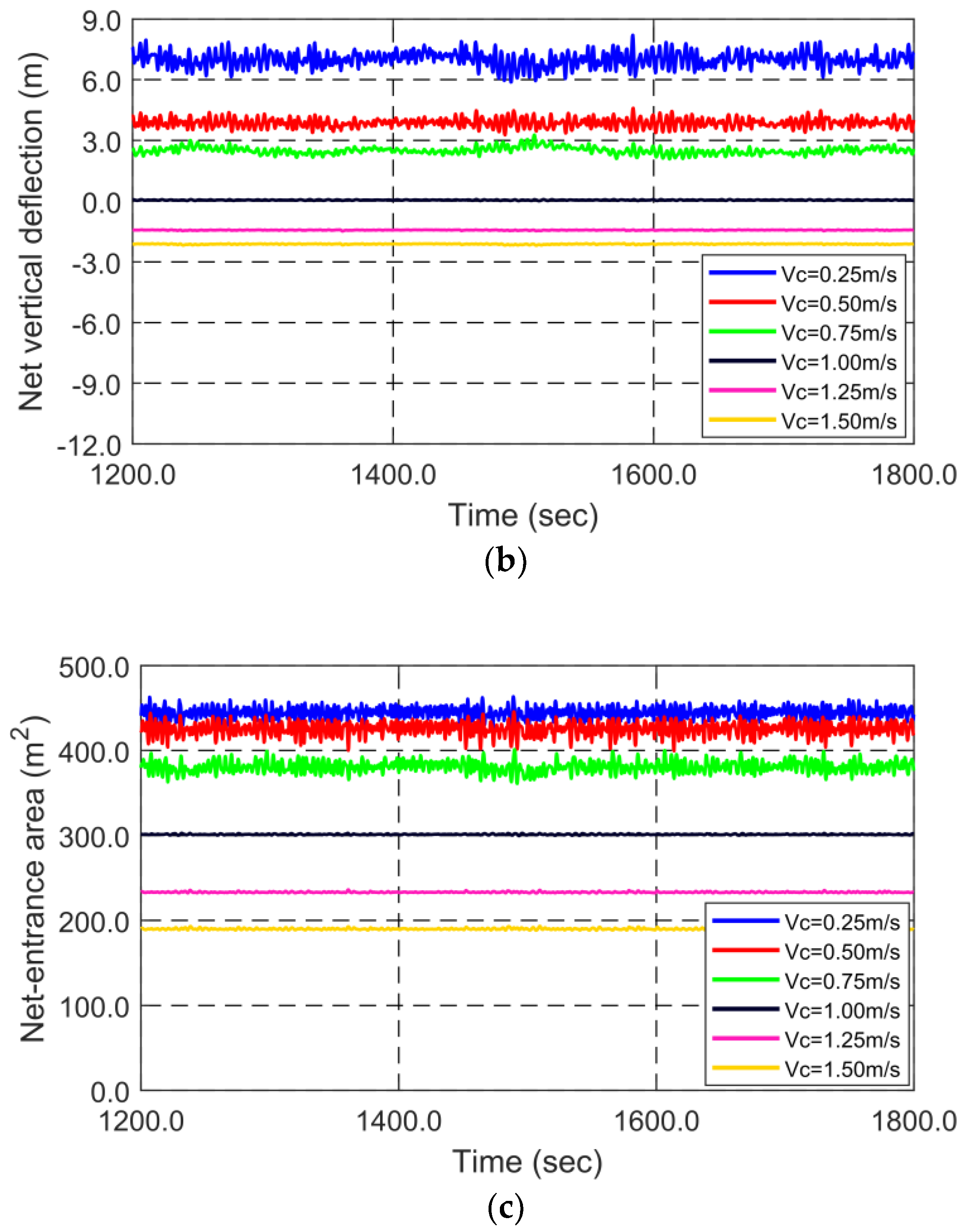
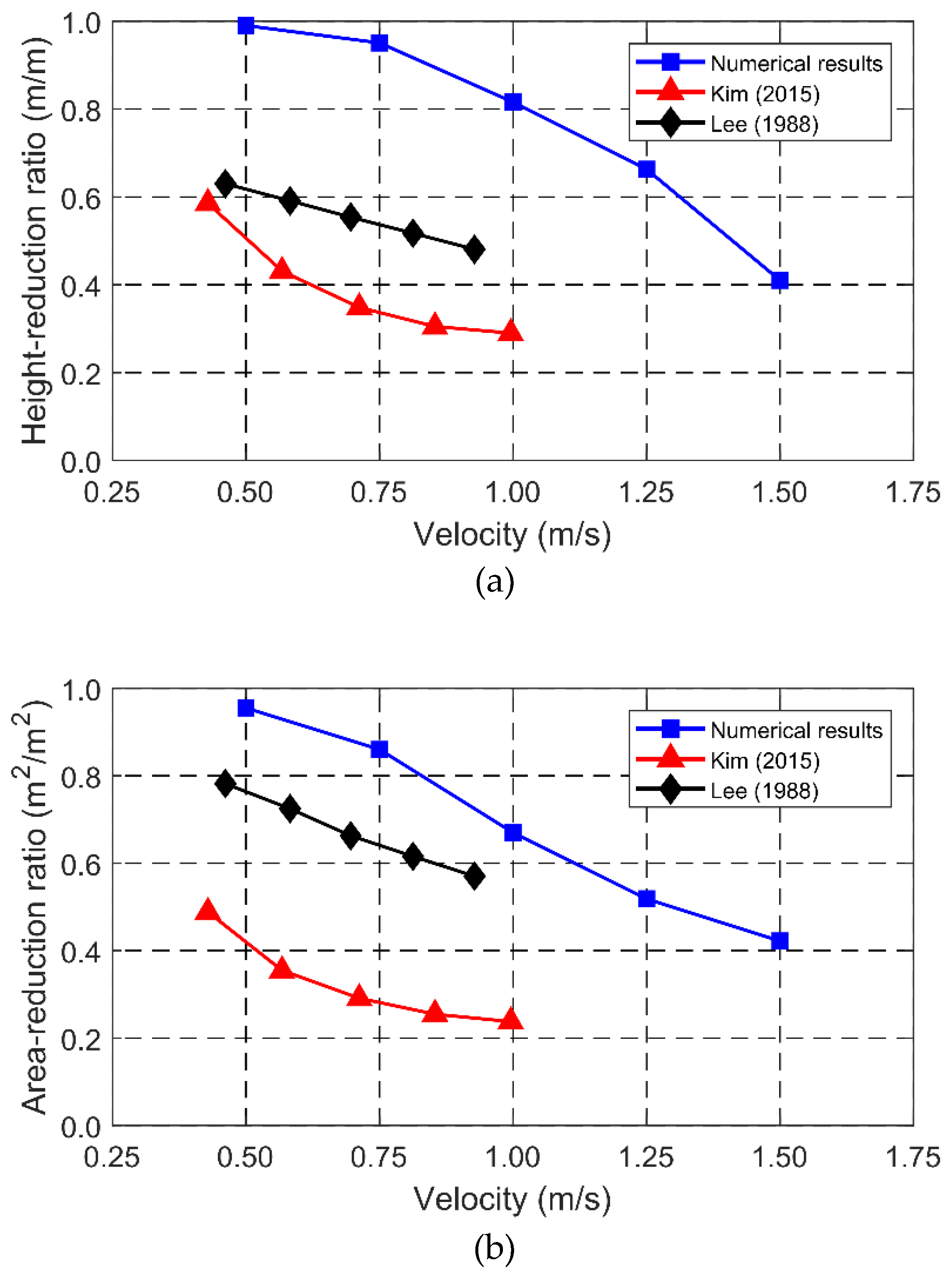
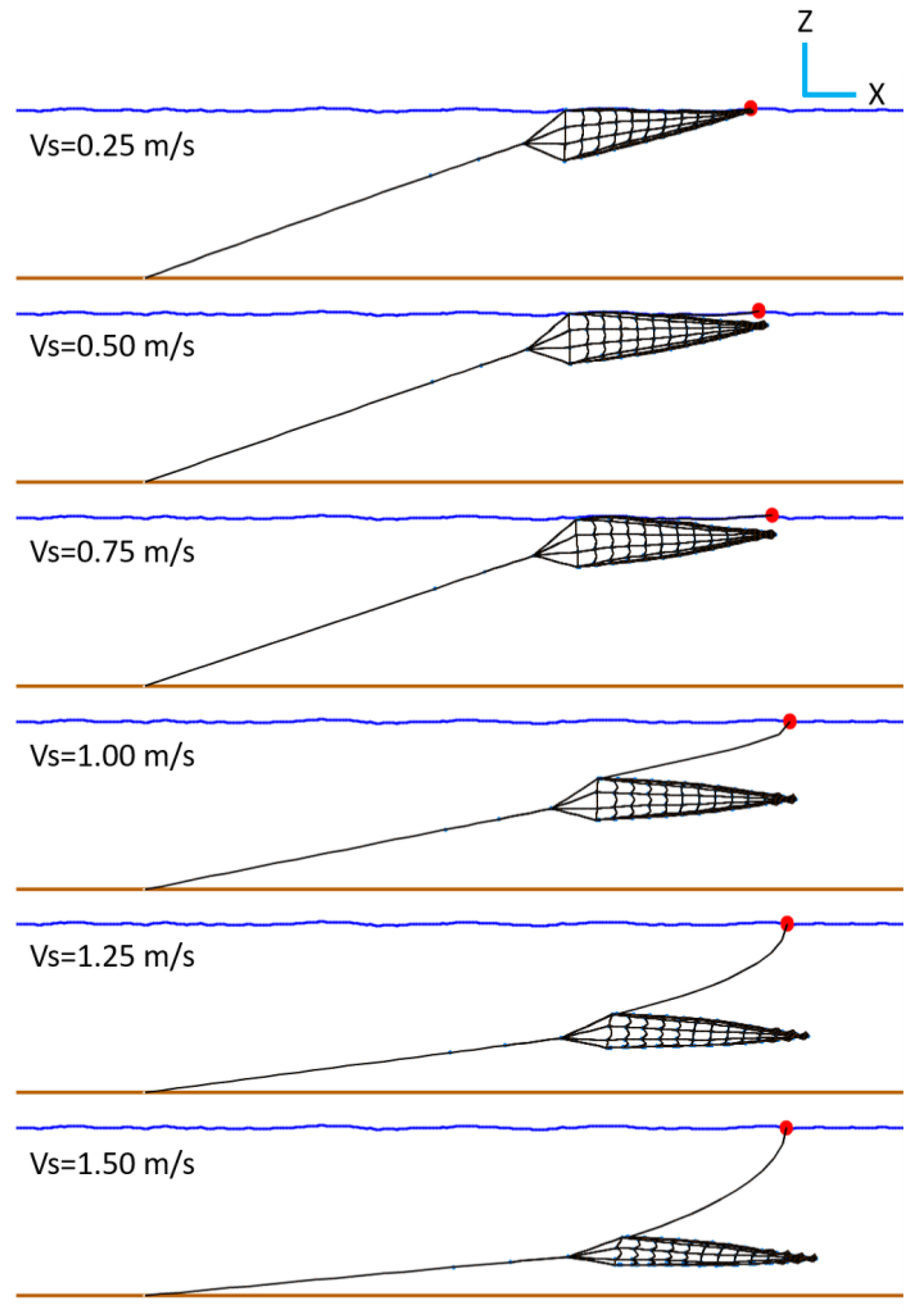
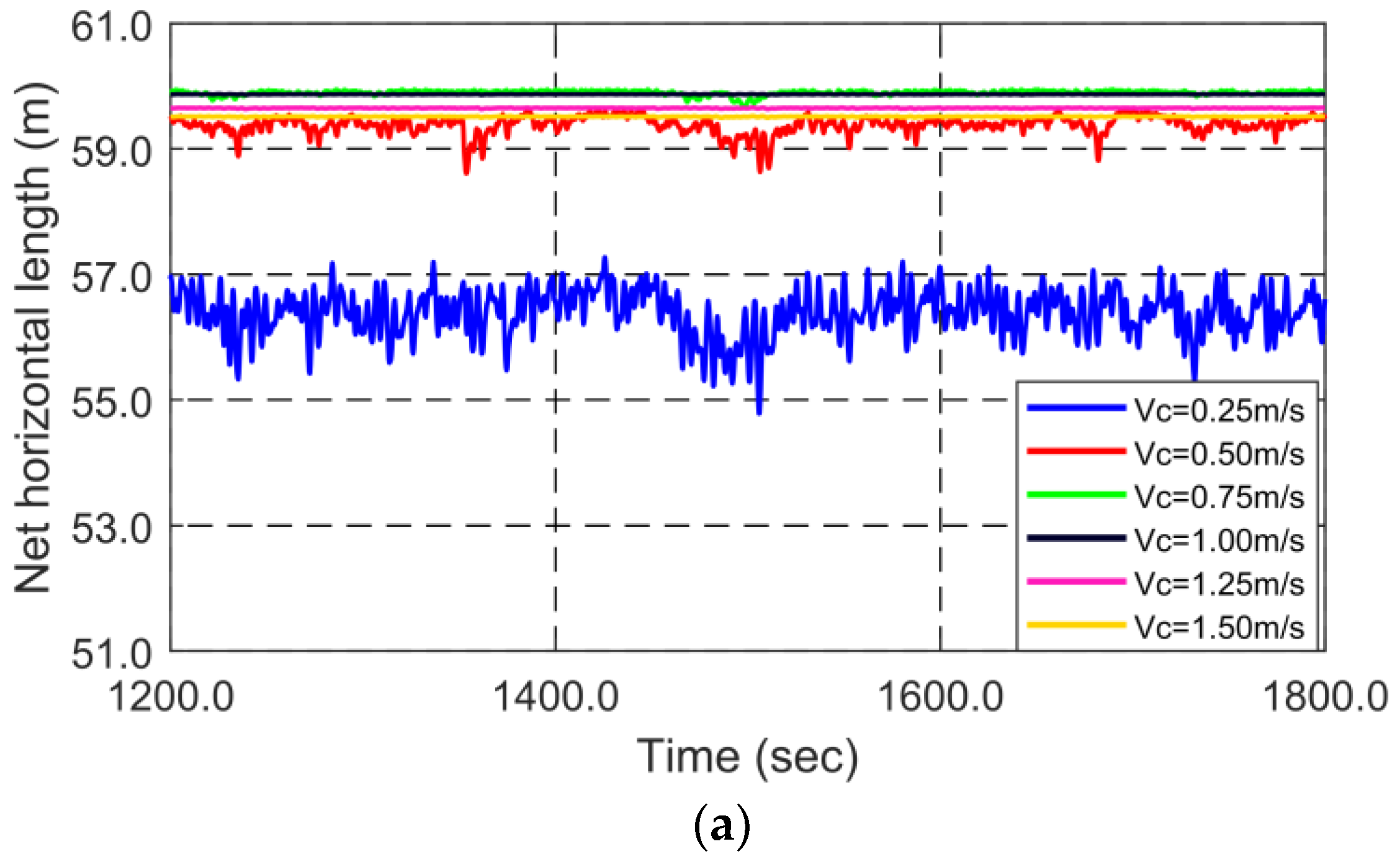
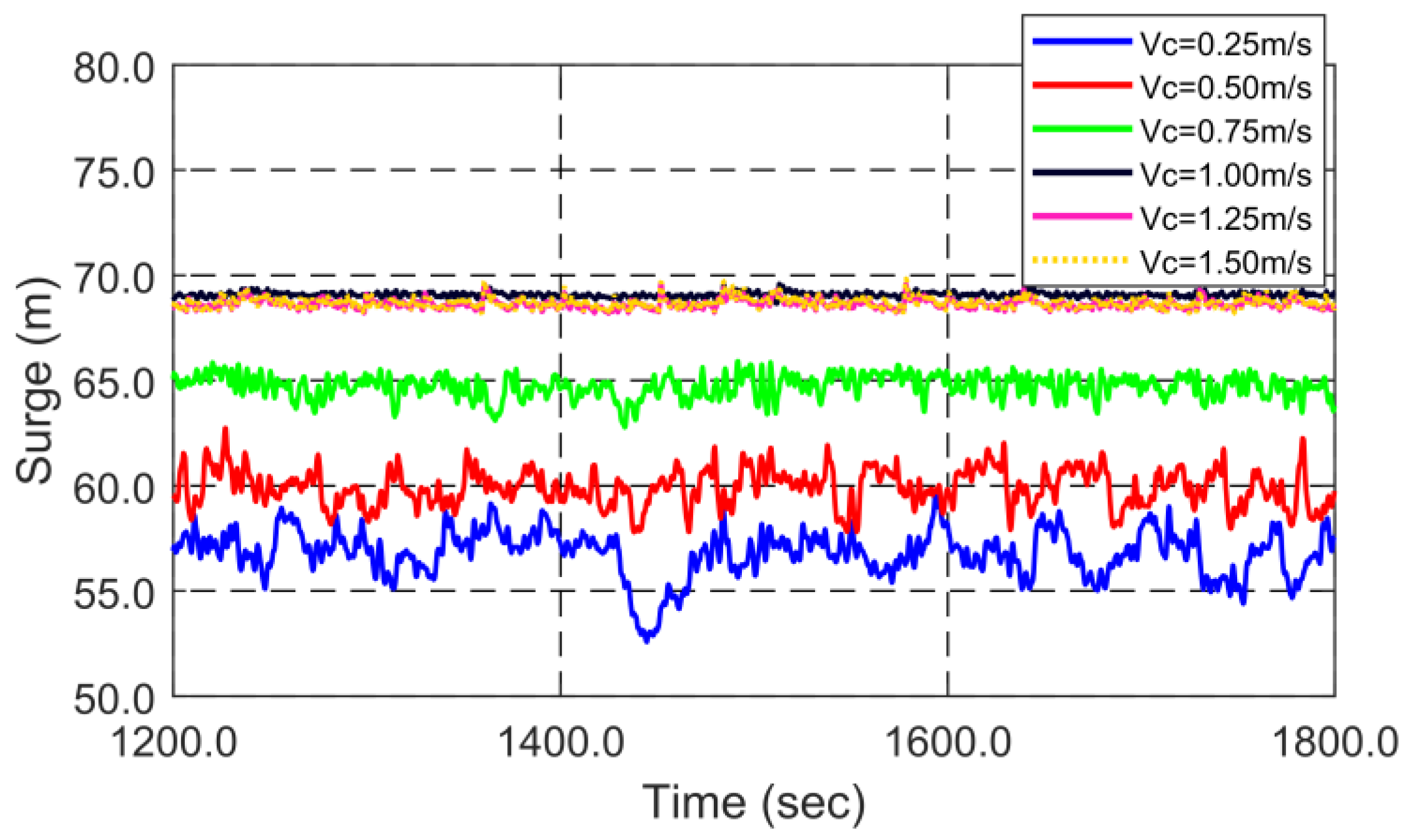
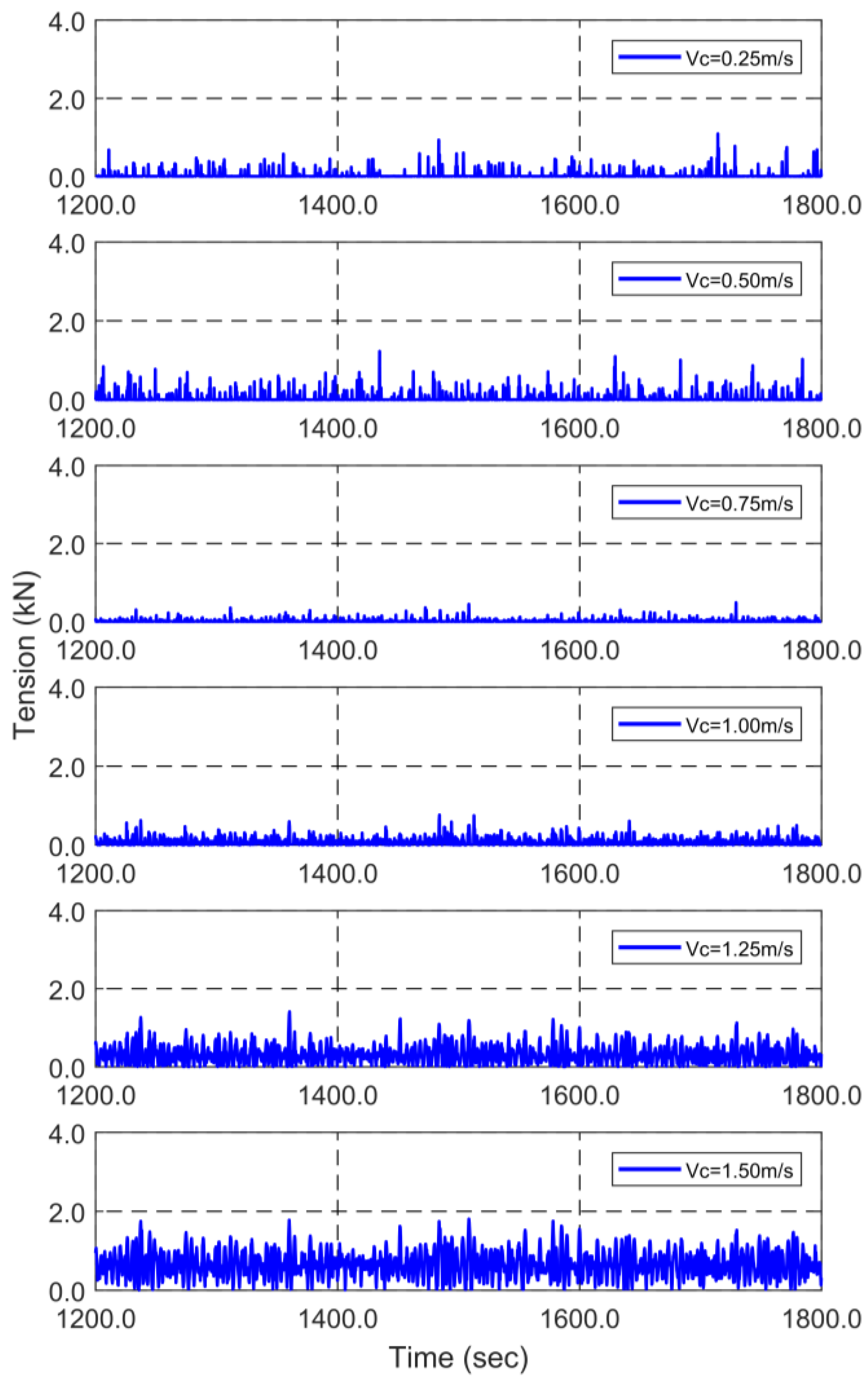
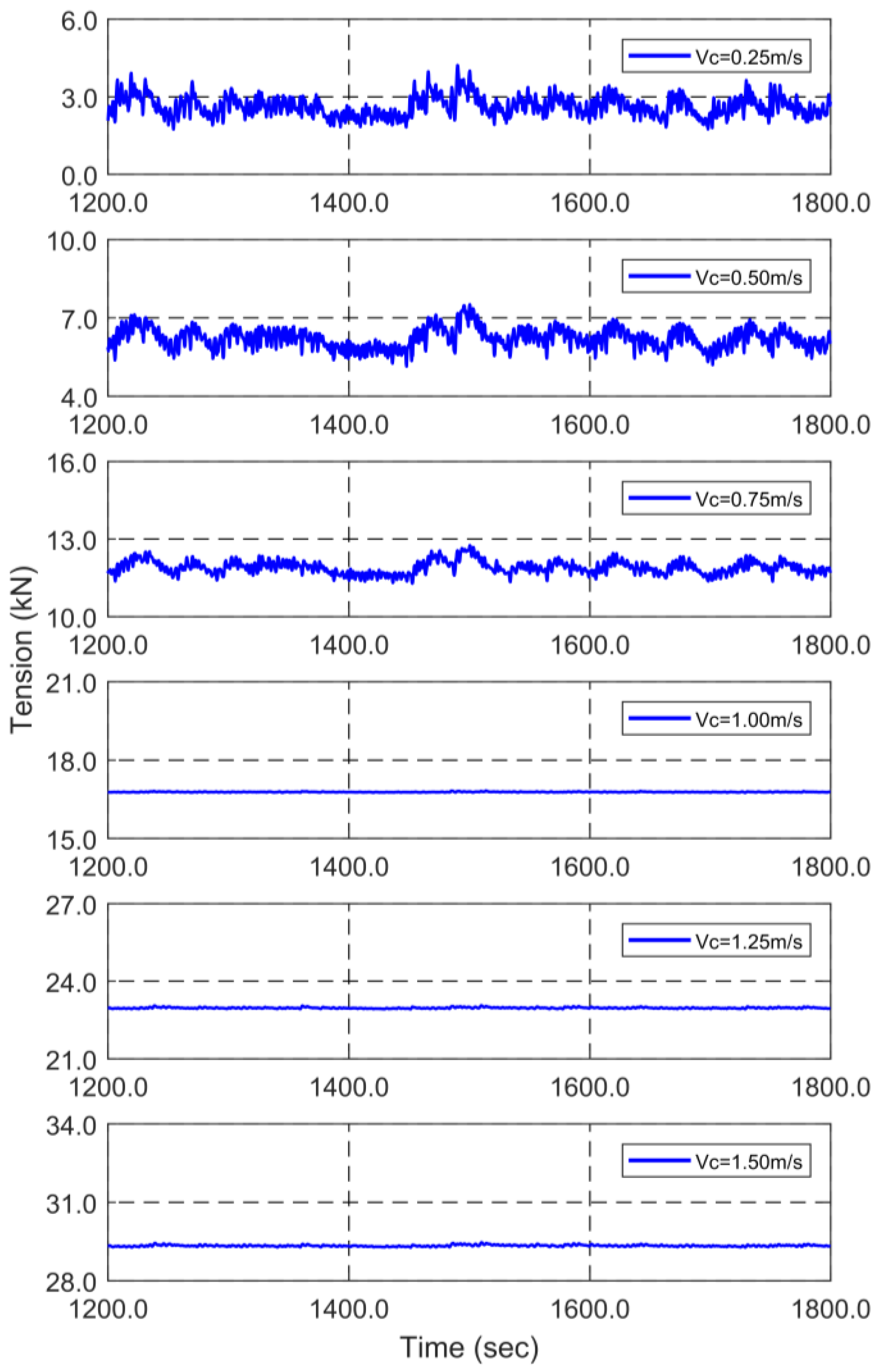
3.1. Effects of Current Velocities

Figure 4 shows height- and area-reduction ratios at different current velocities without wave excitations to validate the numerical stow-net model. The reduction ratio is the ratio of decreased value under current to the value in fully stretched state. The trends of net-entrance height and area are compared with those of previous researches [19,20] as a validation purpose. In the previous research, they considered different types of stow-net designs/materials/solidity ratios and conducted experiments to analyze the behaviors at different current velocities. As shown in Figure 4, the ratios decrease as current velocity rises. Higher current velocity causes higher drag force acting on the net, and the net pulls the head and ground ropes in the current direction decreasing the net-entrance height and area. Since different models/materials are used in the experiments, direct quantitative comparisons are not possible. However, as a qualitative comparison, the general trends (e.g., decreasing ratios with increasing current velocity) in the present numerical simulations coincide with the experimental results.
From this point on, let us consider the dynamic behaviors of the stow net system in steady sheared currents and irregular waves. Higher current velocity contributes to larger submergence depth of the stow net. Once the net floats close to the surface at low current velocity, twisting motions of the assembly might occur by wave excitations that will deteriorate the overall net functionality. The stretching performance of the stow net is also highly dependent on current velocity. Therefore, it is interesting to find the relationships between current velocity and both submergence depth and stretching performance. Figure 5 shows the snapshot of the stow net after 30 min of simulations at different current velocities, under the same wave condition (Hs = 1.0 m Tp = 5.25 s). Figure 6 shows time histories of net horizontal length, net vertical deflection, and net-entrance area of these cases. Table 3 summarizes the statistical results of these parameters for all simulated cases. Figure 5 clearly demonstrates that for current velocity lower than 0.75 m/s, the stow net floats close to the free surface, and the submergence depth of stow net gradually increases with increasing current velocity. It can be expected that as current velocity is lower than 0.75 m/s, the net assembly is significantly affected by wave excitations, which can be further demonstrated in Figure 6. The time-history results demonstrate that the fluctuations in net horizontal length, net vertical deflection, and net-entrance areas decrease with increasing current velocity. If current velocity is higher than 0.75 m/s, we can observe only small variations in those parameters. The net horizontal length is the longest at current velocity of 1.0 m/s, and at lower current velocities, the current force is not enough to enable the net to fully stretch in horizontal direction, as can be observed in Figure 6a. While the net vertical deflection decreases with current velocity, the absolute value is the smallest at current velocity of 1.0 m/s as demonstrated in Figure 6b. Because current velocity decreases with depth, higher current force acts on upper parts of the net and head rope than lower parts of the net and ground rope, which causes vertical deflection. Moreover, as shown in Figure 6c, the net-entrance area decreases as current velocity rises, and significant decreases occur when current velocity is greater than 1.0 m/s. Maintaining the net-entrance area well at high current velocity is directly related to the performance of stow nets.

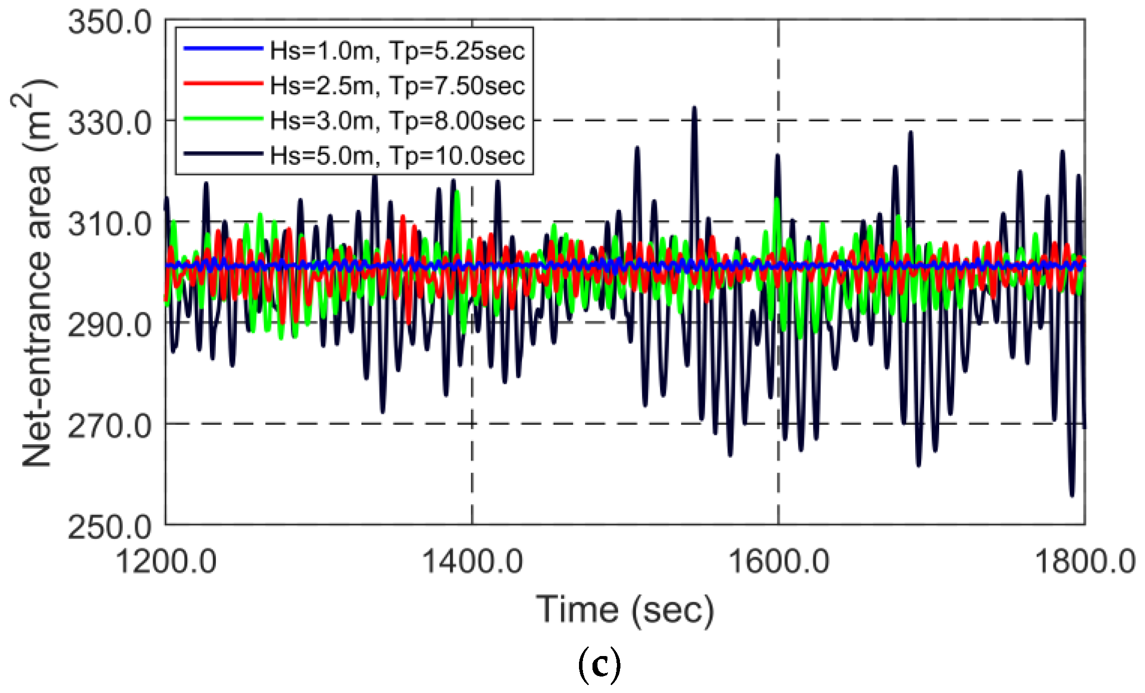
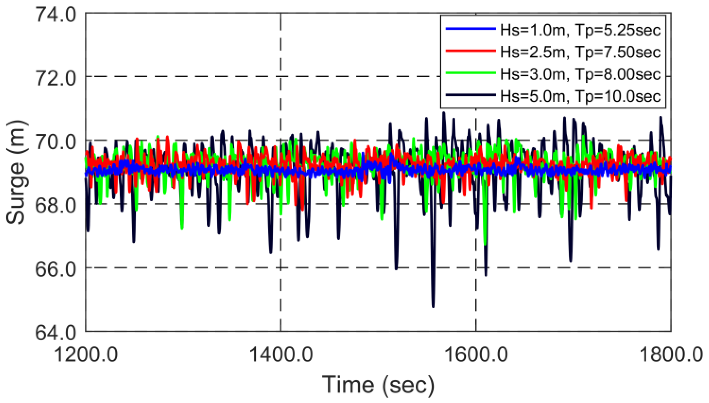
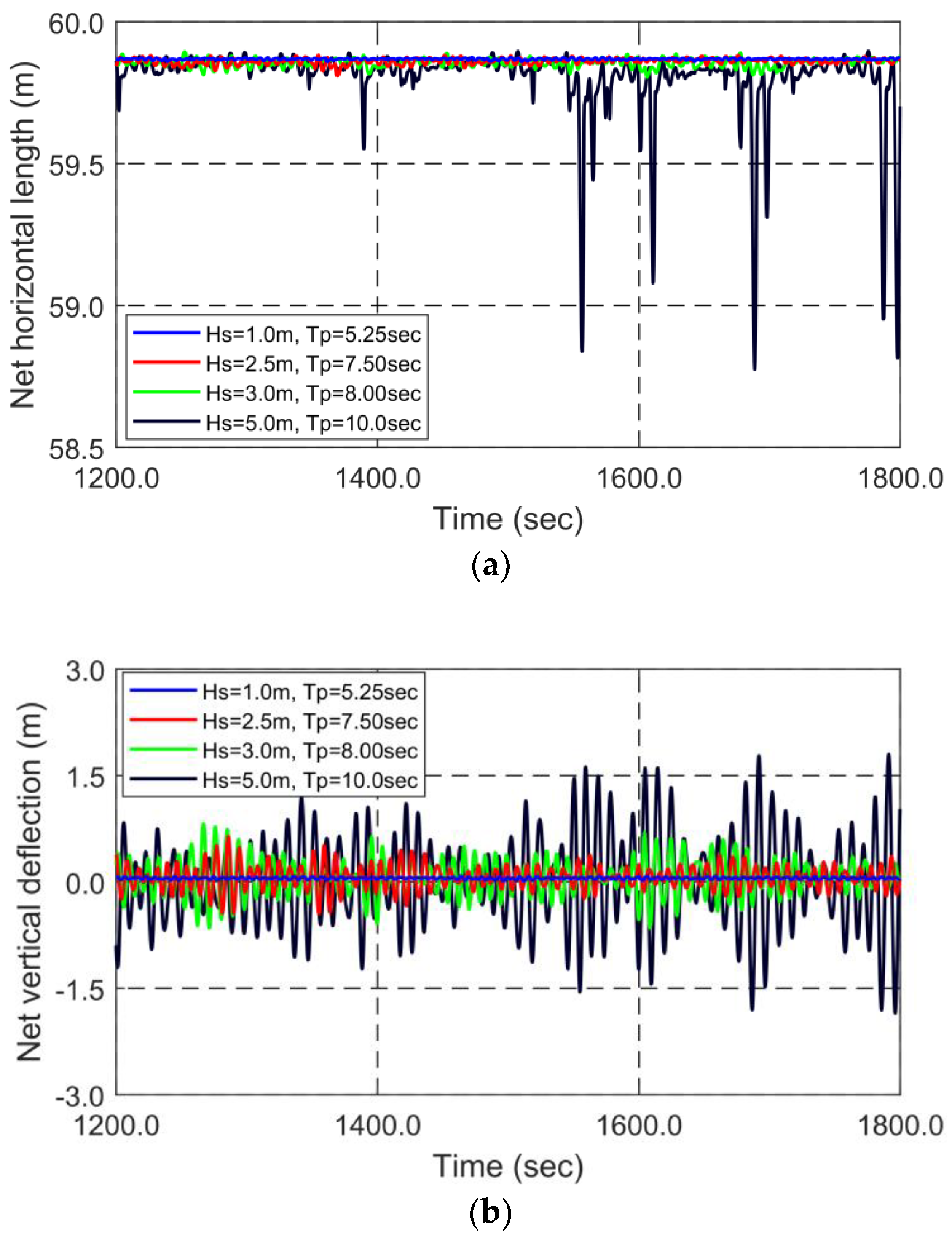
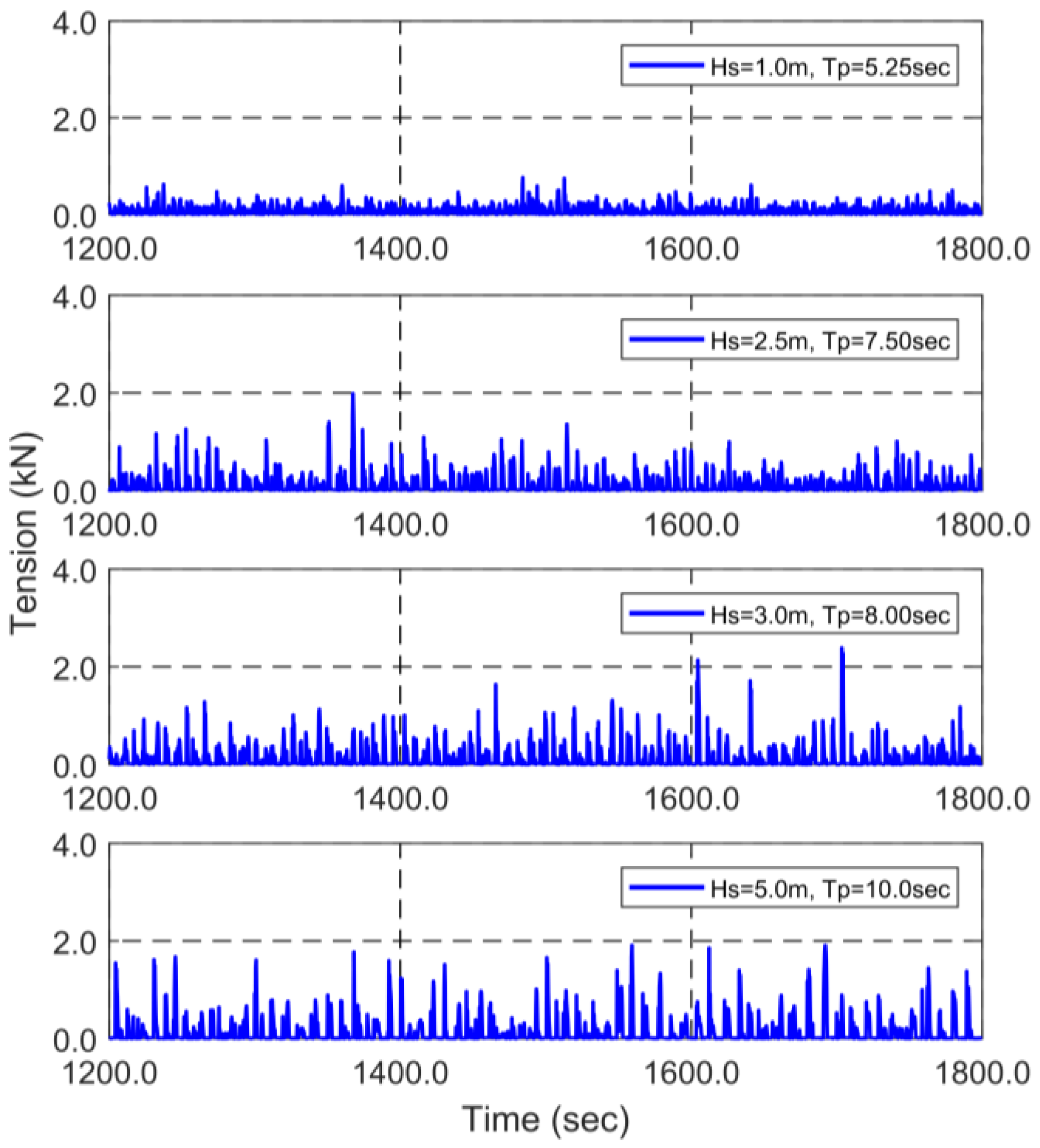
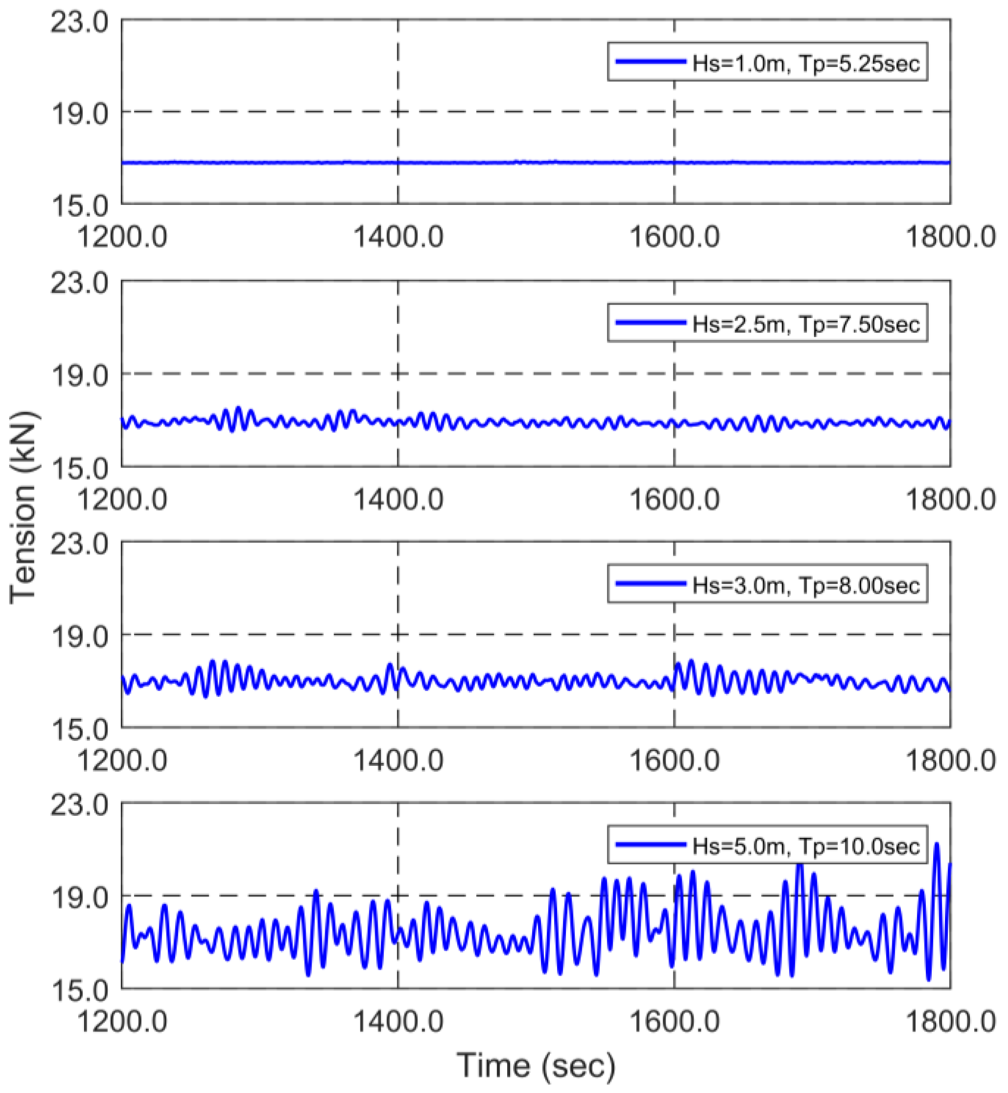
3.2. Effects of Wave Excitations

Figure 7 shows net horizontal length, net vertical deflection, and the net-entrance area with varying wave conditions under the identical current velocity of 1.0 m/s. As can be intuitively expected, larger wave heights cause larger dynamic motions of net assembly. As can be seen in Figure 7a, the dynamic variations of net horizontal length are not significant except for the case of Hs = 5.0 m since the horizontal current force is dominant under the given submergence depth. In addition, the variations of net horizontal length tend to be larger in the negative direction because mooring and net-thread tensions only act on positive extension. As shown in Figure 7b, the dynamic motions of net vertical deflection significantly increase as wave height becomes more than 2.5 m/s mainly due to the flexible threads at the end of the net assembly. The time histories of net-entrance area show that variations of the area are larger in the downward direction because of the side ropes providing tension in positive stretch, as represented in Figure 7c. The stow net is influenced by wave excitations unless the submergence depth is deep enough, considering fast-decaying wave force with depth. Especially, at Hs = 5.0 m, the fluctuations induced by waves are large, which may cause a negative influence on fishing efficiency. More dynamic motions are expected at lower current velocities with smaller submergence depth. The large net notions significantly affect the mooring and rope tensions.

4. Feasibility of Monitoring-Sensor Technology

In this section, the feasibility of monitoring system developed for the stow net is evaluated. Numerical sensors are installed on the location buoy and mooring line #1. Two monitoring sensors measure surge (translational) motions of the buoy and tensions of the mooring line and the rope. Tension data are aimed to efficiently confirm that the fishing gear is not broken or lost. In addition, it might also be feasible to roughly measure environmental conditions and net functionality by the motion and tension data.
Figure 8 and Figure 9 show surge motions of the location buoy in different environmental conditions. Table 4 provides the statistical results of surge motions of buoy, rope tensions, and mooring tensions for all simulated cases. As can be seen in Figure 8, the mean surge motion of the location buoy increases with current velocity up to 1.0 m/s, and then remains with little change after that. The reason is that the mean buoy-surge is significantly affected by net and deeper net means less drag forces. Because submergence depth does not change significantly at low current velocities, the mean buoy-surge increases with increasing current force. In addition, the fluctuations of the location buoy become smaller with the increase of current velocity and submergence depth. At low current velocities, since the submergence depth of the net assembly is shallow, the surge motion of the location buoy is also largely influenced by net motions. As current velocity increases, the net surge motions decrease, which results in smaller buoy-surge motions. As represented in Figure 9, at the same current velocity, the mean buoy-surge remains little changed, while its dynamic surge motions increase with wave heights.
Figure 10 and Figure 11 (also Table 4) show the time histories of rope tension in different environmental conditions. Generally, as current velocity is lower than 1.0 m/s, rope tension gradually decreases with increasing current velocity. The opposite trend can be observed if current velocity is greater than 1.0 m/s. At high current velocity, the net is more submerged, and the rope becomes taut (see Figure 5), and thus the dynamic tensions increase. In this case, both surge and heave motions of buoy contribute to the rope dynamic tensions. At low current velocity, the net is close to surface and rope becomes almost horizontal (see Figure 5) and the tension is caused by the relative surge motions between the net and buoy. Interestingly, both effects become minimal at the current velocity of 0.75 m/s. As shown in Figure 11 and Table 4, when the current velocity is fixed at 1.0 m/s, the rope dynamic tensions increase with wave heights, as can intuitively be expected. When the rope is slack, the location buoy can also function as wave-measurement buoy since it vertically follows wave surface.
Figure 12 and Figure 13 show the time histories of mooring tensions under different environmental conditions. They show that the maximum mooring tension increases with increasing current velocity. It is mainly due to the increase of static tension in stronger currents. However, the variations (or dynamics) of mooring tensions decrease because of the increased submergence depth, so less wave effects, in stronger currents. On the other hand, Figure 13 shows the mooring tensions for various wave heights at fixed current velocity. In this case, the dynamic (or maximum) mooring tension increases as wave height increases, as can intuitively be expected.
From the simulated results, wave/current conditions, net functionality, and net submerged depth can roughly be predicted by observing buoy surge motions and rope/mooring tensions. Rope and mooring tensions will also provide information whether the location buoy and/or the net assembly are lost. Therefore, monitoring sensors can be applied for that kind of purpose after enough simulated data are accumulated with a target stow-net design. The numerical simulations are also very useful in selecting the proper range of motion and tension sensors. Sophisticated and integrated research is needed for the optimal design of highly functional monitoring system.

5. Conclusions

Computationally more efficient 3D equivalent net models are developed. With the model, time-domain numerical simulations are conducted for analyzing the global performance and monitoring feasibility of a stow net in wave/current conditions of the southwest coast of South Korea. The stow-net design is based on one of actual designs used in South Korea. The input sea conditions are obtained from the three-year-real-sea data. The simulated general behaviors of the stow net are compared against the observed behaviors from previous experiments, and reasonable agreements are obtained. Current force is dominant to determine the submergence depth and stretching performance of the stow net. High current velocity contributes to smaller net height and entrance area. Net motions and the corresponding dynamic mooring tensions are significant as the submergence depth becomes shallower at lower current velocity, and wave heights increase. By using the accumulated simulation data of a target stow net, wave/current conditions, net location, net survivability and functionality, and net submerged depth can roughly be predicted by observing the signals of monitoring sensors for buoy surge motions and rope/mooring tensions. Tension data will be able to determine whether the net assembly and/or the location buoy are lost.

Author Contributions

All authors have equally contributed to publish this article related to design of target model, validation of numerical modeling, parametric study, analysis, and writing.

Funding

This research was a part of the project titled “Development of Automatic Identification Monitoring System for Fishing Gears”, funded by the Ministry of Oceans and Fisheries, Korea.

Conflicts of Interest

The authors declare no conflict of interest.

References

  1. Page, B.; McKenzie, J.; McIntosh, R.; Baylis, A.; Morrissey, A.; Calvert, N.; Haase, T.; Berris, M.; Dowie, D.; Shaughnessy, P.D. Entanglement of australian sea lions and new zealand fur seals in lost fishing gear and other marine debris before and after government and industry attempts to reduce the problem. Mar. Pollut. Bull. 2004, 49, 33–42. [Google Scholar] [CrossRef] [PubMed]
  2. Lee, K.-N.; An, H.-C. A Study for Systematic Management of Coastal or Offshore Fishery; Korea Fisheries Association & National Fisheries Research and Development Institute: Busan, Korea, 2007; pp. 1–334.
  3. Jin, C.; Choi, J.; Kim, M.; Kim, K. Dynamic responses of a stow net using measured environmental data in the southwest coast of Korea. In Proceedings of the Fall Conference of the Korean Society of Ocean Engineers, Geoje, Korea, 19–20 October 2017; pp. 262–265. [Google Scholar]
  4. Kim, J.-K.; Yoon, G.-D. A study on the design of the stern stow net. J. Korean Soc. Fish. Technol. 1999, 35, 343–352. [Google Scholar] [CrossRef]
  5. Kristiansen, T.; Faltinsen, O.M. Modelling of current loads on aquaculture net cages. J. Fluids Struct. 2012, 34, 218–235. [Google Scholar] [CrossRef]
  6. Lee, C.-W.; Kim, Y.-B.; Lee, G.-H.; Choe, M.-Y.; Lee, M.-K.; Koo, K.-Y. Dynamic simulation of a fish cage system subjected to currents and waves. Ocean Eng. 2008, 35, 1521–1532. [Google Scholar] [CrossRef]
  7. Huang, C.-C.; Tang, H.-J.; Liu, J.-Y. Effects of waves and currents on gravity-type cages in the open sea. Aquacult. Eng. 2008, 38, 105–116. [Google Scholar] [CrossRef]
  8. Huang, C.-C.; Pan, J.-Y. Mooring line fatigue: A risk analysis for an spm cage system. Aquacult. Eng. 2010, 42, 8–16. [Google Scholar] [CrossRef]
  9. Zhao, Y.-P.; Li, Y.-C.; Dong, G.-H.; Teng, B.; Gui, F.-K. Numerical simulation of hydrodynamic behaviors of gravity cage in current and waves. Int. J. Offshore Polar Eng. 2009, 19, 97–107. [Google Scholar]
  10. Zhao, Y.-P.; Gui, F.-K.; Xu, T.-J.; Chen, X.-F.; Cui, Y. Numerical analysis of dynamic behavior of a box-shaped net cage in pure waves and current. Appl. Ocean Res. 2013, 39, 158–167. [Google Scholar] [CrossRef]
  11. Cifuentes, C.; Kim, M. Numerical simulation of fish nets in currents using a morison force model. Ocean Syst. Eng. 2017, 7, 143–155. [Google Scholar]
  12. Cifuentes, C.; Kim, M. Hydrodynamic response of a cage system under waves and currents using a morison-force model. Ocean Eng. 2017, 141, 283–294. [Google Scholar] [CrossRef]
  13. Cifuentes, C.; Kim, M. Dynamic analysis for the global performance of an spm-feeder-cage system under waves and currents. China Ocean Eng. 2015, 29, 415–430. [Google Scholar] [CrossRef]
  14. Chen, H.; Christensen, E.D. Simulating the hydrodynamic response of a floater–net system in current and waves. J. Fluids Struct. 2018, 79, 50–75. [Google Scholar] [CrossRef]
  15. Ko, K.S.; Kim, Y.H. Model experiment of stow net. Korean J. Fish. Aquat. Sci. 1979, 12, 201–207. [Google Scholar]
  16. Sun, M.C.; Zhang, J.; Xu, L.X. Size selectivity of diamond and square mesh codends for hairfin anchovy setipinna taty in chinese stow net fisheries. Fish. Sci. 2006, 72, 530–539. [Google Scholar] [CrossRef]
  17. Cho, S.-K.; Park, C.-D.; Kim, H.-Y.; Cha, B.-J. Catches comparison according to the codend mesh size of stow net on anchor in the west sea of korea. J. Korean Soc. Fish. Technol. 2010, 46, 1–9. [Google Scholar] [CrossRef]
  18. Cho, S.-K.; Cha, B.-J.; Kim, H.-Y. Catches of main species and bycatch according to the codend mesh sizes of stow net on anchor in the west sea of korea. J. Korean Soc. Fish. Technol. 2011, 47, 88–98. [Google Scholar] [CrossRef]
  19. Kim, S.; Lee, D.; Lim, J.; Park, S. Model test on the net mouth shape of a gape net according to current speeds in jindo area, korea. J. Korean Soc. Fish. Technol. 2015, 51, 146–153. [Google Scholar] [CrossRef]
  20. Lee, B.-G.; Kim, J.-K.; Lee, J.-H. Study on the improvement of stow net fishing technique and the enlargement of fishing ground to the distant waters-1. Model experiment of the net. J. Korean Soc. Fish. Technol. 1988, 24, 55–64. [Google Scholar]
  21. Orcina. Orcaflex Manual Version 9.8a. 2015. Available online: https://www.orcina.com/Support/OrcaFlex/9.8/index.php (accessed on 1 September 2018).
  22. Faltinsen, O. Sea Loads on Ships and Offshore Structures; Cambridge University Press: London, UK, 1993. [Google Scholar]
  23. DeCew, J.; Tsukrov, I.; Risso, A.; Swift, M.; Celikkol, B. Modeling of dynamic behavior of a single-point moored submersible fish cage under currents. Aquacult. Eng. 2010, 43, 38–45. [Google Scholar] [CrossRef]
  24. Choc, Y.-I.; Casarella, M.J. Hydrodynamic resistance of towed cables. J. Hydronaut. 1971, 5, 126–131. [Google Scholar] [CrossRef]
  25. Dnv-os-e301: Offshore Standard-Position Mooring. Available online: https://rules.dnvgl.com/docs/pdf/DNV/codes/docs/2010-10/OS-E301.pdf (accessed on 27 July 2018).
  26. Fredheim, A. Current Forces on Net Structures. Doctoral Dissertation, NTNU, Trondheim, Norway, April 2005. [Google Scholar]
  27. Wheeler, J. Methods for Calculating Forces Produced by Irregular Waves. In Proceedings of the Offshore Technology Conference, Houston, TX, USA, 18–21 May 1969. [Google Scholar] [CrossRef]
  28. Longridge, J.; Randall, R.; Zhang, J. Comparison of experimental irregular water wave elevation and kinematic data with new hybrid wave model predictions. Ocean Eng. 1996, 23, 277–307. [Google Scholar] [CrossRef]
  29. KMA. Available online: Http://www.Kma.Go.Kr/help/basic/help_03_02.Jsp (accessed on 27 July 2018).
Figure 1. 3D (a) and 2D (b) views of the stow net and description of all analyzed parameters.
Applsci 08 01517 g001
Figure 2. Measured current velocity (a) significant wave height (b), and peak period (c) of southwest coast of South Korea in years of 2014–2016.
Applsci 08 01517 g002aApplsci 08 01517 g002b
Figure 3. Theoretical JONSWAP wave spectrum and reproduced spectrum from wave time histories using FFT (a) and wave time histories generated from JONSWAP wave spectrum (b) for Hs = 1.0 m, Tp = 5.25 s.
Applsci 08 01517 g003
Figure 4. Height (a)- and area (b)-reduction ratios at different current velocities without wave excitations for validation.
Applsci 08 01517 g004
Figure 5. Snapshot of the entire stow net at varying current velocities under the same wave condition (Hs = 1.0 m, Tp = 5.25 s) at T = 1800 s.
Applsci 08 01517 g005
Figure 6. Time histories of net horizontal length (a), net vertical deflection (b), and net-entrance area (c) at varying current velocities under identical wave excitations (Hs = 1.0 m, Tp = 5.25 s).
Applsci 08 01517 g006aApplsci 08 01517 g006b
Figure 7. Time histories of net horizontal length (a), net vertical deflection (b), and net-entrance area (c) in varying wave conditions under the identical current velocity (Vc = 1.0 m/s).
Applsci 08 01517 g007aApplsci 08 01517 g007b
Figure 8. Time histories of surge motion of the location buoy at different current velocity under identical wave excitations (Hs = 1.0 m, Tp = 5.25 s).
Applsci 08 01517 g008
Figure 9. Time histories of surge motion of the location buoy in different wave conditions under identical current velocity (Vc = 1.0 m/s).
Applsci 08 01517 g009
Figure 10. Time histories of rope tension at different current velocities under identical wave excitations (Hs = 1.0 m, Tp = 5.25 s).
Applsci 08 01517 g010
Figure 11. Time histories of rope tension in different wave conditions under identical current velocity (Vc = 1.0 m/s).
Applsci 08 01517 g011
Figure 12. Time histories of mooring tension at different current velocities under identical wave excitations (Hs = 1.0 m, Tp = 5.25 s).
Applsci 08 01517 g012
Figure 13. Time histories of mooring tension in different wave conditions under identical current velocity (Vc = 1.0 m/s).
Applsci 08 01517 g013
Table 1. Material properties and design parameters.
ItemValue (Type)Unit
NetStretching Length60m
Width30m
Height15m
MaterialPolyethylene-
Density970kg/m3
Head and ground ropesLength30m
Diameter0.1m
MaterialOak-
Density750kg/m3
Weight located to ground ropeMass150kg
Number2-
Buoy located to head ropeVolume0.243m3
Number2-
Buoyancy to weight ratio (BWR)Net entrance1.5-
Net1.01-
Mooring line and ropeDiameter9, 14, 34mm
MaterialPolypropylene-
Density910kg/m3
Location buoyMaterialStyrofoam-
Density50kg/m3
Volume0.2m3
Diameter0.73m
Table 2. Environmental conditions for parametric study.
Wave Condition
Significant wave height, Hs (m)1.02.53.05.0
Peak period, Tp (s)5.257.58.010.0
Enhancement parameter, γ1.01.01.03.3
Current Condition
Surface current velocity (m/s)0.25, 0.50, 0.75, 1.00, 1.25, 1.50
Table 3. Statistical data of net horizontal length, net vertical deflection and net-entrance area for all simulated cases.
Environmental ConditionNet Horizontal LengthNet Vertical DeflectionNet-entrance Area
Hs (m)Tp (s)Vc (m/s)Average (m)STD (m)Average (m)STD (m)Average (m2)STD (m2)
1.05.250.2556.3880.3647.0010.354444.2616.663
0.5059.3800.1403.8700.213425.4027.371
0.7559.8970.0382.5070.167380.8296.424
1.0059.8690.0020.0530.013301.2560.487
1.2559.6500.004-1.4320.010233.2140.538
1.5059.5130.004-2.1230.016189.9850.772
2.57.50.5058.5230.6173.8920.675412.75315.592
0.7559.6380.3312.3220.525371.37813.182
1.0059.8600.0100.0600.164300.3523.182
1.2559.6450.009-1.4290.090233.0451.633
1.5059.5110.009-2.1130.060190.1711.603
3.08.00.5058.2780.8593.8780.888406.87219.095
0.7559.5240.4712.3800.673366.84315.899
1.0059.8550.0140.0590.253299.4874.764
1.2559.6430.011-1.4270.140232.8842.223
1.5059.5110.012-2.1080.090190.1961.863
5.010.00.5057.8661.4813.2491.578396.39929.666
0.7559.1910.9341.9531.257359.04526.331
1.0059.8040.1350.0060.643294.51212.315
1.2559.6410.019-1.4070.380231.3915.248
1.5059.5140.029-2.0850.251189.5732.987
Table 4. Statistical results of surge motion of the location buoy, rope tension, and mooring tension for all simulated cases.
Environmental ConditionSurge Motion of the Location BuoyRope TensionMooring Tension #1
Hs (m)Tp (s)Vc (m/s)Average (m)STD (m)Maximum (kN)STD (kN)Maximum (kN)STD (kN)
1.05.250.2556.7881.1191.0920.0894.2170.387
0.5059.9010.8681.2300.1207.5110.390
0.7564.7250.5310.4890.04112.7500.253
1.0069.0640.1120.7620.09816.8280.010
1.2568.6430.2121.4120.23523.0610.021
1.5068.6880.2461.8070.33929.4630.029
2.57.50.5060.3881.6066.2560.23911.9440.987
0.7564.4731.0922.3000.16715.4390.687
1.0069.2010.3151.9810.20417.5360.157
1.2569.1750.3152.5330.44123.5710.137
1.5069.3000.3762.7720.58329.9970.140
3.08.00.5060.6841.4672.0480.20912.3731.152
0.7564.6501.1523.1800.19315.4560.820
1.0069.2110.4482.3880.24217.8790.269
1.2569.2950.3492.7240.49824.0180.235
1.5069.4530.3962.9520.64930.4060.233
5.010.00.5060.0282.0934.6930.25716.8721.985
0.7564.8971.6512.7660.20018.9291.520
1.0069.0670.8381.9080.29521.2290.980
1.2569.3160.5262.6000.58926.9840.882
1.5069.5920.5332.8110.72233.2000.870

