Article

Effectiveness of Distributed vs. Concentrated Volt/Var Local Control Strategies in Low-Voltage Grids

Institute of Energy Systems and Electrical Drives, TU Wien, Vienna 1040, Austria
*
Author to whom correspondence should be addressed.
Appl. Sci. 2018, 8(8), 1382; https://doi.org/10.3390/app8081382
Submission received: 28 June 2018 / Revised: 10 August 2018 / Accepted: 13 August 2018 / Published: 16 August 2018

Abstract

:
This paper introduces a novel local Volt/var control strategy in a low-voltage smart grid. Nowadays, various Volt/var local control strategies built on customer photovoltaic inverters, e.g., cosφ(P) and Q(U), are introduced to mitigate the upper voltage limit violations in feeders with high prosumer share. Nevertheless, although these strategies are further refined by including more local variables, their use is still very limited. In this study, the effects of a new concentrated Volt/var local control strategy in low-voltage grids are investigated. Concentrated var-sinks, e.g., coils-L(U), are set at the end of each violated feeder. The concentrated local control strategy L(U) is compared with the distributed cosφ(P) and Q(U) strategies. Initially, both control strategies are theoretically investigated, followed by simulations in a test feeder. Finally, the expected practical significance of the findings is verified through simulations in a real typical urban and rural grid. Additionally, the impact of the different local control strategies used in low-voltage grids on the behavior of the medium-voltage grid is analyzed. The results show that the concentrated Volt/var control strategy eliminates the violation of upper voltage limit even in longer feeders, where both distributed local strategies fail. In addition, the concentrated L(U) local control causes less reactive power exchange on the distribution transformer level than the distributed cosφ(P) and Q(U) strategies. Therefore, the reactive power exchange with the medium-voltage grid and thus the distribution transformer loading are smaller in the case of concentrated local control strategy.

1. Introduction

Technological progress has led to a rapid growth of the use of distributed photovoltaic electricity production. However, this trend did not prevail for a long time because it failed to match the required voltage quality in low-voltage grids (LVG). Cases of violation of upper voltage limit have been identified [1,2,3,4,5]. Very soon, it becomes clear that in distribution grids, the reactive power support is needed when distributed generation (DG) is in operation [1,2,6,7,8].
The literature extensively discusses the possibility of using the smart inverter of photovoltaic (PV) facilities to eliminate the upper voltage limit violations in low-voltage (LV) smart grids. Each inverter is upgraded with cosφ(P) or Q(U) local controls [9,10,11]. The grid operator determines the reactive power contribution of the PV inverters by fixed or variable target values [12]. The latter can be set by remote control, i.e., online presetting of target values, or by schedules [13]. The set value may be a constant power factor [12,13,14,15,16,17], constant reactive power [12,13,14,16,17], constant voltage at a given bus [13,18], Q(U) characteristic [11,14,15,16,17,18,19,20,21,22,23], or cosφ(P) characteristic [12,14,16,17,21,22,23]. P and Q are the active and reactive power provided by inverter; cosφ is the power factor set at inverter level; U is the voltage of the feeder bus where the inverter is connected. These methods are further refined by including more local variables [14,15,16,18,19,21]. Although all of these methods act on local variables, many studies require a communication infrastructure to coordinate them by sending set points [18] or certain parameters [20]. This complicates the practical implementation of the local Volt/var control strategies, and therefore, their use is still very limited. Furthermore, PV inverters in cosφ(P) or Q(U) operation mode causes an excessive reactive power flow, thus increasing considerably the grid loss and loading of the distribution transformers (DTRs) [24,25]. The constant power factor operation mode even exacerbates the problem of unnecessary Q-flows and grid losses [21].
All of the local Volt/var control strategies mentioned above provoke distributed var-sinks throughout the length of the feeder. As an alternative, in this work, we introduce concentrated var-sinks at the end of each violated feeder. The concentrated var-sink is modeled as a variable inductance L, i.e., concentrated local control strategy L(U). We discuss the effectiveness of distributed versus concentrated Volt/var local control strategies in LVG in three cases. Firstly, their theoretical behavior is analyzed and compared in a very simplified model. Secondly, the behavior of distributed Q(U) and concentrated L(U) local control is investigated and compared in a test overhead feeder. Thirdly, the impact of both control strategies on the reactive power exchange of an urban and rural real grid is explored and compared. Additionally, their effect on the medium-voltage grid (MVG) is analyzed. Finally, conclusions are presented.

2. Theoretical Behavior of Distributed versus Concentrated Volt/var Local Control Strategy

In the European design, LVGs are very extended. In the rural areas, the feeder length can reach up to 2 km. They have a ratio R/X > 1, and usually are operated radially. R and X are the resistance and inductance of the feeders, respectively. The feeder-ups to the customer plants are distributed more or less homogeneously. Thus, it is assumed that the length of the feeder segments between two customers is approximately equal.
The large-scale rooftop–PV integration across the LVGs with European design requires reactive power support to eliminate the violation of the upper voltage limit caused by the significant feedback of the active power flow. The local distributed Volt/var local control strategy, as defined below, is the most popular countermeasure to solve the problem of voltage violation in these cases.

2.1. Definitions

Distributed Volt/var local control strategy is when Volt/var local controls (e.g., cosφ(U) or Q(U)) are applied to reactive power devices (e.g., PV-inverters), which are connected to various locations throughout the length of the feeder in order to mitigate the violation of the upper voltage limit. Distributed var-sinks are reactive power consumptions in various locations of the feeder provoked by the distributed Volt/var local controls. Figure 1 shows an overview of the distributed Q(U) local control strategy or rather distributed var-sinks.
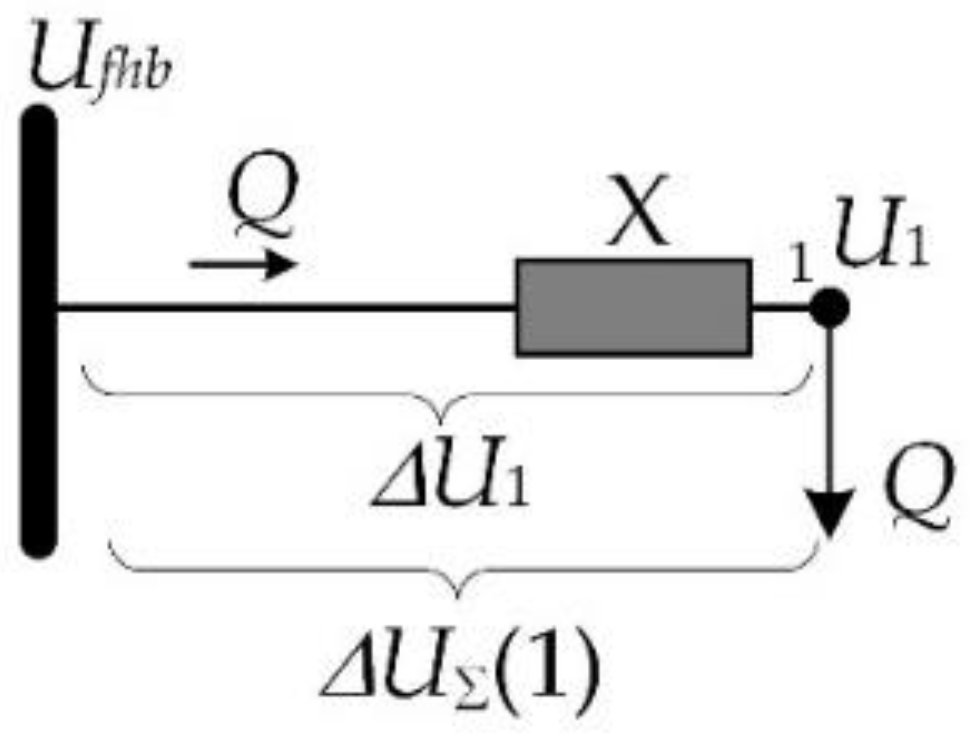
Concentrated Volt/var local control strategy is when one reactive power device (e.g., coil or inductance, L) upgraded with a Volt/var local control (e.g., L(U)) is applied mostly at the end of the feeder to mitigate the violation of the upper voltage limit. A concentrated var-sink is the reactive power consumption of the reactive device at the connection point. Figure 2 shows an overview of the concentrated L(U) local control strategy or rather concentrated var-sink.
Both control strategies are theoretically analyzed in the following.

2.2. Theoretical Background

Figure 3 shows an overview of a feeder segment with feedback active power supply. Figure 3a shows its equivalent circuit. The feeder segment is modeled through its series impedance, while the parallel impedance is neglected because it plays only a small role in voltage regulation, since the nominal voltage of LVGs is very small. In a typical LV feeder with large-scale PV penetration, active power P is supplied back to the medium-voltage grid (MVG), while reactive power Q is withdrawn from inverters to maintain the voltage below the upper limit. Figure 3b shows the corresponding phasor diagram. The reference is the phasor voltage U ¯ 1 , i.e., U ¯ 1 = U 1 .
The impedance, Z ¯ , which carries the current of the prosumer, causes the voltage drop as in:
Δ U ¯ 1 = U ¯ 1 U ¯ 2 = Z ¯ · I ¯ ,
where Δ U ¯ 1 —phasor voltage drop; U ¯ 1 —phasor voltage at the load bus or at the end of the feeder segment; U ¯ 2 —phasor voltage at the head of the feeder segment; Z ¯ = R + jX—feeder segment series impedance; I ¯ —phasor current.
The apparent power of the prosumer is calculated as in:
S 1 ¯ = U ¯ 1 · I ¯ = P 1 j Q 1 ,
where S 1 ¯ —phasor apparent power of the prosumer; P1—active power of the prosumer; Q1—reactive power of the prosumer.
Since the load current is expressed as in:
I ¯ = P 1 + j Q 1 U 1 .
Substituting I ¯ into Equation (2) results in:
Δ U ¯ 1 = ( R + jX ) · P 1 + j Q 1 U 1 = P 1 · R Q 1 · X U 1 + j P 1 · X + Q 1 · R U 1 = Δ U R + j Δ U X ,
where ΔUR—real part of the voltage drop; ΔUX—imaginary part of the voltage drop.
As illustrated in Figure 3b, the voltage drop through the feeder segment has two components: one in phase (ΔVR) modifies the voltage amplitude, and the other one in phase quadrature (ΔVX) rotates the voltage vector. The latter has no significant impact on the amplitude of the voltage drop; therefore, ΔVX is neglected. Under these assumptions, the amplitude of voltage drop is expressed as:
Δ U 1 = Δ U R = P 1 · R Q 1 · X U 1 .
Although P has the most significant influence on the voltage drop amplitude on the feeder, the purpose of this chapter is to investigate only the impact of the reactive power on it. Therefore, P is neglected, and Equation (5) is simplified as follows:
Δ U 1 = Q 1 · X U 1 .
Since the X of the feeder segment is very small, reactive losses are neglected (ΔQ ≈ 0), and the feeder segment flows fulfill the equation:
Q 1 = Q 2 .
Based on Equations (6) and (7), an equation is derived below to calculate the voltage drop at a feeder with distributed var-sinks.

2.3. Distributed Var-Sinks

Figure 4 shows the equivalent circuit of an LV feeder with distributed var-sinks. A feeder with n buses is connected to the MVG through the DTR. One of the feeder ends is connected to the LV bus of the DTR, the so-called feeder–head–bus (fhb). This bus bar is not counted as a feeder bus. The other end is called the feeder–end–bus (feb), and is numbered bus 1. Based on these assignments, the segment number of the feeder is equal to the number of its buses n. Since Equation (6) includes only X, each feeder segment is modeled by a reactance of equal value. It is also assumed that the same reactive power Q (var-sink) is absorbed on each bus. This corresponds to the real case when the same-sized PV facilities are installed to each customer, and the cosφ(P) control is used. We assume that all of the customers are in the same weather zone, so their PVs produce the same P, while the inverters absorb the same Q.
The voltage drop over the whole feeder is equal to the sum of the voltage drop of each feeder segment as in:
Δ U T o t a l = Δ U Σ ( n ) = i = 1 n Δ U i ,
where ΔUTotal—total voltage drop of a feeder; n—number of feeder segments; ΔUΣ—voltage drop over the whole feeder; ΔUi—voltage drop in the feeder segment i.
The total voltage drop on a feeder is calculated by Equation (9) as follows:
Δ U T o t a l = U 1 U f h b = U f e b U f h b ,
where Ufhb—voltage at the feeder–head–bus bar; Ufeb—voltage at the feeder–end–bus bar.
The total voltage drop of a feeder with distributed var-sinks, fd(n), is function of n as long as the X, Q, and U1 = Ufeb are constant. It is derived from Equations (6) and (8), and is defined by the following recursive formula:
Δ U T o t a l = Δ U Σ ( n ) = f d ( n ) = Q · X U 1 k = 2 n k · Q · X U 1 f d ( k 1 ) .
The list of the first four terms of Equation (10) is given in the Appendix.

2.4. Concentrated Var-Sink

Figure 5 shows the equivalent circuit of an LV feeder with a concentrated var-sink. The latter is set at the end of the feeder, since almost all of the LV feeders with a large PV share show the highest voltage value, and even the highest sensitivity ∂U/∂Q at their ends [14].
The total voltage drop of a feeder with a concentrated var-sink, fc(n), is a function of n as long as X and U1 = Ufeb are constant. fc(n) is derived from Equations (6) and (7), and is defined by:
Δ U c ( n ) = f c ( n ) = Q c ( n ) · n · X U 1 .

2.5. Distributed versus Concentrated Var-Sinks

The comparison of distributed var-sinks with the concentrated var-sink is done when both cause the same total voltage drop on the feeder as in:
Δ U c ( n ) = Δ U Σ ( n ) ,
or:
f c ( n ) = f d ( n ) ,
The concentrated consumption of reactive power, Qc, at bus one is set so that the voltage drop over the feeder is equal to that of the distributed case, as in:
Q c ( n ) · n · X U 1 = Q · X U 1 + k = 2 n k · Q · X U 1 f d ( k 1 ) ,
Q c ( n ) · n = Q + k = 2 n k · Q · U 1 U 1 f d ( k 1 ) ,
Q c ( n ) = 1 n ( Q + k = 2 n k · Q · U 1 U 1 f d ( k 1 ) ) ,
The evaluation criteria are:
  • the reactive power exchange, Qex,
  • the voltage drop behavior, and
  • the voltage profile.
Calculations are made for 20 buses and a feeder segment with 0.1-km length and an inductance of X = 0.03557 Ω, which is a typical value for a LV overhead line. The var-sink is set to Q = 1.0 kvar and U(1) = 207.0 V = 0.9 p.u.

2.5.1. Reactive Power Exchange

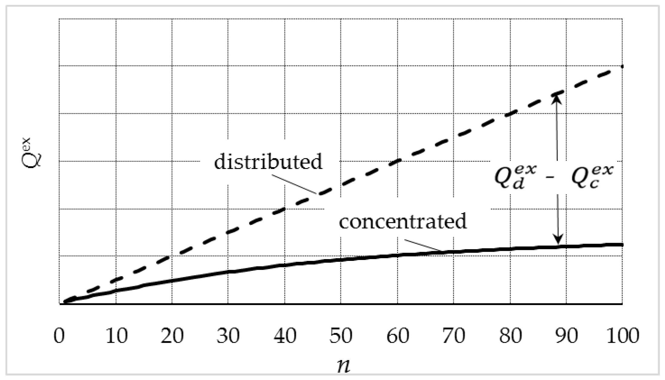
Figure 6 shows Qex as a function of the bus number, n, for the distributed and concentrated var-sink cases. Qex for the distributed var-sinks case is calculated as in:
Q d e x ( n ) = n · Q ,
while for the concentrated var-sink case:
Q c e x ( n ) = Q c ( n ) .
The results of the calculations show that the reactive power needed, i.e., Qex, to achieve the same total voltage drop is smaller in the case of a concentrated var-sink than in the case of the distributed var-sinks. Qex is the same for both strategies only when the feeder has one bus, n = 1. With increasing n, the difference between Q d e x and Q c e x increases monotonically.

2.5.2. Voltage Drop Behavior

Figure 7 presents the theoretical voltage drop amplitude in every feeder segment as a function of the feeder segment number for the distributed and concentrated var-sink cases. As expected, in the distributed case, the largest voltage drop falls at the feeder begin on the feeder segment fs20, because n·Q flows there. Meanwhile, the smallest one drops on the last feeder segment, fs1, because only Q flows there. In contrast, the voltage drop in the concentrated case falls evenly on all of the feeder segments.

2.5.3. Voltage Profile

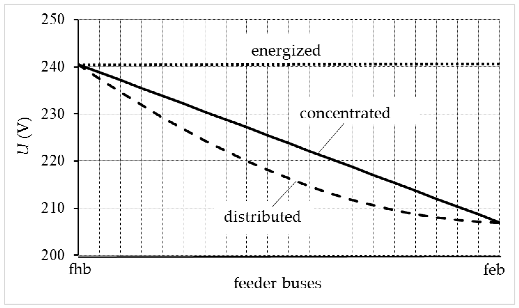
Figure 8 shows the theoretical voltage profile for the distributed and concentrated var-sink cases. Although the voltages at fhb and feb are equal in both cases, the voltage values in the distributed case are lower than in the concentrated one, especially in the middle of the feeder. In the case of distributed var-sinks, the voltage profile behaves convexly, while in the concentrated var-sink case, it shapes linear.
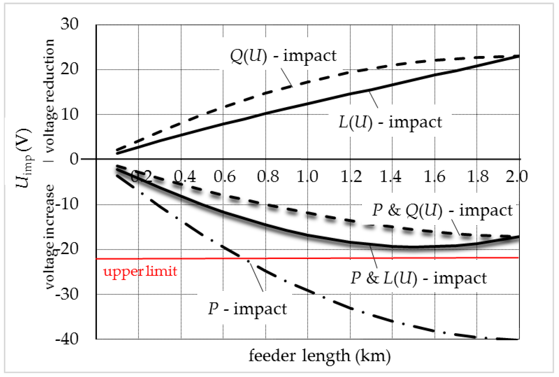
To understand the shape of the voltage profiles, the impact of distributed and concentrated var-sink cases on their behavior is explicitly shown in Figure 9. This impact is calculated by:
U d i m p ( i ) = U f h b e n e r g U d ( i ) ,
and:
U c i m p ( i ) = U f h b e n e r g U c ( i ) .
where U d i m p ( i ) —the impact of distributed var-sinks on node i, U f h b e n e r g energization voltage at feeder head node, Ud(i)—voltage at node i in the case of distributed var-sinks, U i m p c ( i ) —the impact of concentrated var-sinks on node i for the distributed and concentrated control strategies, respectively.
The impact on voltage profile in the case of distributed var-sinks shows a concave behavior, while in the case of a concentrated var-sink, it shows a linear one. Therefore, the distributed var-sinks exert a greater impact on voltage profile than the concentrated var-sink.
As a conclusion, to achieve the same total voltage drop, the distributed var-sinks absorb more reactive power than the concentrated var-sink. The surplus of the reactive power absorbed by the distributed var-sinks pushes down the voltage profile without need, and overloads the grid.
The mathematical calculations in this chapter were possible because we made many assumptions and simplifications. To get closer to a real case, we then performed relevant simulations in a test grid.

3. Comparison of Different Control Strategies in a Test Feeder

To validate the conclusions drawn from the theoretical calculations, simulations are performed in a test network using PSS SINCAL. Figure 10 depicts the equivalent circuit of a LV feeder with n = 20, where 20 households are connected. An overhead line with R’ = 0.3264 Ω/km and X’ = 0.3557 Ω/km is simulated, whereby each feeder segment is 0.1 km long. To investigate the effects of different control strategies on the feeder behavior, it is assumed that the prosumers do not have their own consumption (Pload = Qload = 0). The largest possible PV penetration is simulated by installing a 5.0-kWp PV facility on each house roof. The Q(U) control is applied on each PV inverter, or only the L(U) control is applied at the end of the feeder.
Figure 11 shows a schematic presentation of the power flows when Q(U) is applied. Figure 11a presents the active and reactive power flows supplied by the PV inverters as red and blue colored, respectively. Each PV facility injects its peak active power Pinv = 5 kW into the grid. The active power flow at the feeder beginning is defined by the number of PV facilities, their production Pinv, and feeder loss, ΔPd. The latter modifies the active power flows at the feeder beginning. Each inverter consumes reactive power; Qinv conforms with its Q(U) characteristic, as shown in Figure 11b. They are over-dimensioned by a factor of 1:0.9 to enable reactive power support with cos(φ) = 0.9 also during peak active power production. The main goal of using Q(U) local control is the elimination of violations of upper voltage limit. Normally, the dead band of the characteristic and the slope gradient are defined to cause minimal losses and reactive flow by avoiding oscillations [21]. Since in our case the simulated feeder is about two kilometers long, the dead band of the characteristic is set as narrow to eliminate all of the voltage violations [25]. The reactive power flow at the beginning of the feeder—i.e., Qex—is defined by the number of PV facilities, their individual Q(i) production, and the feeder loss ΔQd.
Figure 12 depicts a schematic presentation of the active and reactive power when the concentrated L(U) local control strategy is exercised. L(U) is modeled as a variable inductance that is connected when the Uset-point is exceeded. Both active and reactive feeder loss, ΔPc and ΔQc, respectively, increase the power flows at the beginning of the feeder. The reactive power consumption of the sink (coil) is set at the feeder end, and the feeder loss ΔQc defines the reactive power flow at the feeder beginning.
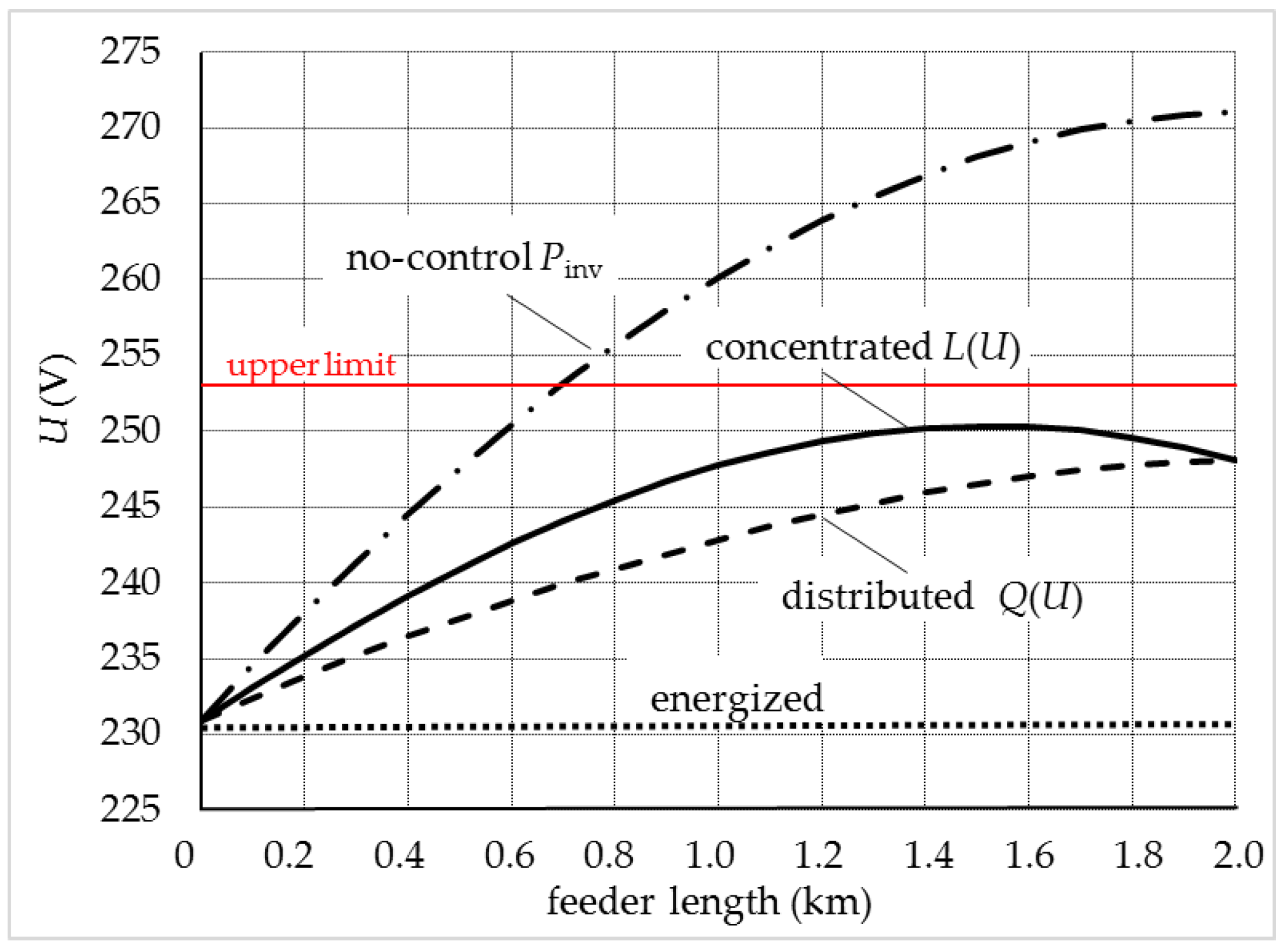
In the following, the influence of active and reactive power on the voltage profile is analyzed in detail. Figure 13 presents the voltage profiles for different control strategies. When no control is applied, Pinv provokes the violation of the upper voltage limit. The voltage violation begins at node 15 (0.6 km from the feeder head bus) and reaches 8.85% at the feeder–end–bus (node 1, U(1) = 271.06 V). The use of the Q(U) or L(U) control strategy eliminates all of the voltage violations and stabilizes the voltage at the feeder–end–bus at 1.08 p.u. In both cases, the voltage profile shows a concave behavior, but the concavity caused by the Q(U) control is weaker than the one caused by the L(U) control strategy. As well as the theoretical results, Q(U) achieves lower voltage profile values than the L(U) control. This is because the control strategy Q(U) causes higher reactive power consumption than L(U). This behavior is discussed in detail below.
Figure 14 depicts the particular impact of the injected active power, the absorbed reactive power caused by different control strategies, and the impact of their combination on the shape of the voltage profile. The P-impact curve shows that the distributed active power injection along the feeder continuously increases the voltage on it to reach the maximum value at its end. Q(U) and L(U) impact the shape of the voltage profile as in the theoretical case discussed above. The combined P and Q(U) increases the voltage by keeping it well below the upper limit, whereas the combined P and L(U) increases the voltage more by keeping it just below the upper limit.
Figure 15 shows the amplitude of voltage drop, |ΔU|, in each feeder segment caused by Pinv, distributed Q(U), and concentrated L(U) control strategies. The |ΔU| caused by Pinv reaches the maximal value at the feeder beginning, fs20. The |ΔU| caused by the distributed Q(U) shapes as in the theoretical case discussed above. In both cases, |ΔU| steadily decreases to reach the minimum value at the feeder–end–bus, fs1. Whereas, the |ΔU| caused by the concentrated L(U) shapes differently from the theoretical case shown in Figure 7. The |ΔU| is not equal in all of the feeder segments. It is slightly increased at the beginning of the feeder, then begins to diminish up to the middle and further remains almost constant. The reason of the increase is the reactive loss, ΔQc = 15.29 kvar (see Table 1), which is neglected in the theoretical case. ΔQc is about 42% of Q c e x .
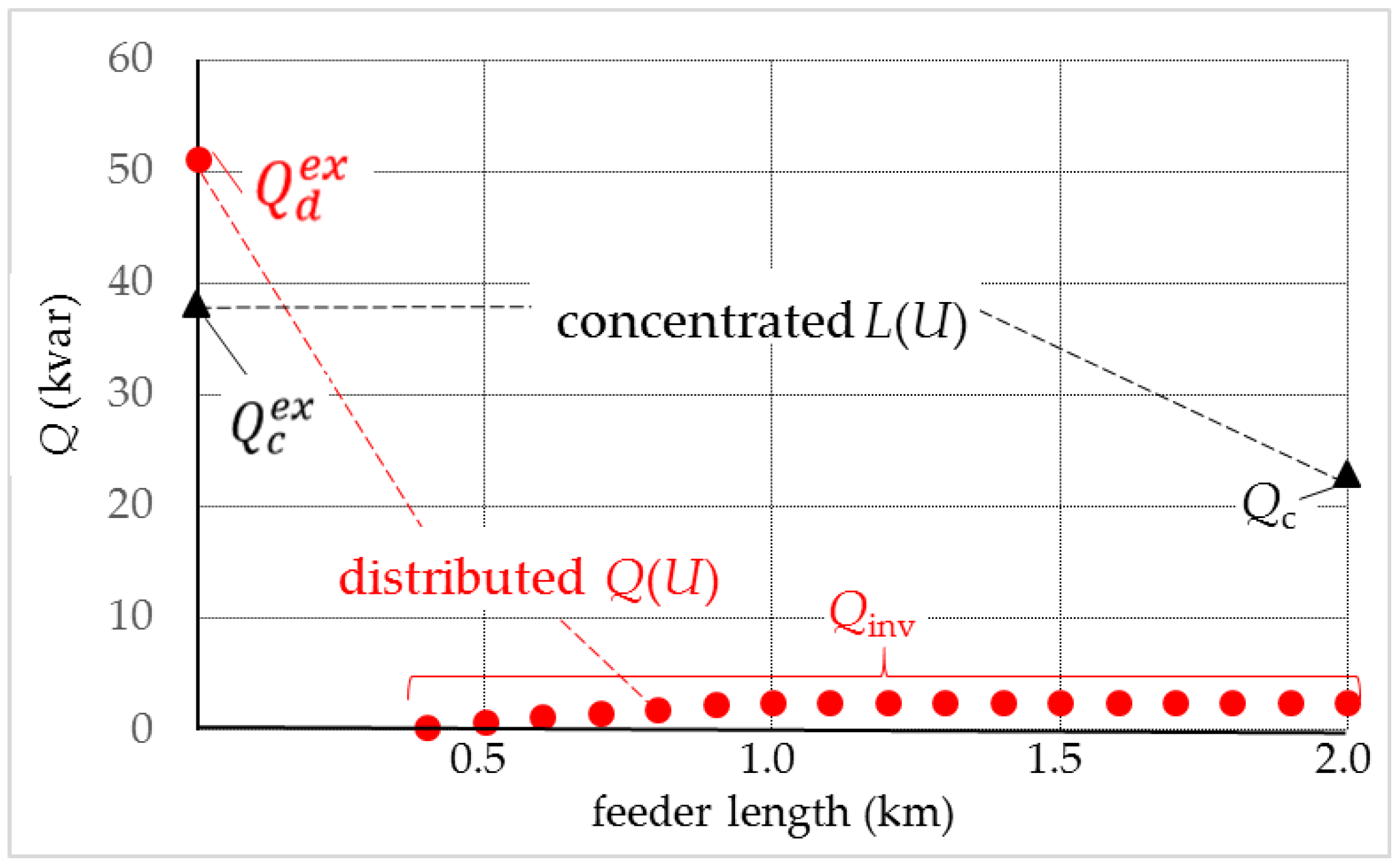
Table 1 shows the reactive power consumption, loss, and Qex for different control strategies. Meanwhile, Figure 16 presents a graphical overview of the consumed reactive power flows and Qex for the distributed Q(U) and concentrated L(U) control strategies. All of the inverters together consume more reactive power than the concentrated coil: 34.52 kvar and 22.77 kvar, respectively. Also, reactive power loss is higher for the distributed Q(U) local control strategy, 16.55 kvar, than for the concentrated L(U) local control strategy, 15.29 kvar. For the distributed control strategy, Qex is calculated by:
Q d e x = i = 1 n Q i n v ( i ) + Δ Q d ,
where Q d e x —reactive power exchange with distributed Q(U) control strategy; Qinv(i)—reactive power consumption of the inverter I; n—number of inverters; ΔQd—feeder reactive power losses with the distributed Q(U) control strategy, and for the concentrated one by:
Q c e x = Q c + Δ Q c ,
where Q c e x —reactive power exchange with concentrated L(U) control strategy; Qc—coil reactive power consumption; ΔQc—feeder reactive power losses with the concentrated L(U) control strategy.
Simulations have shown that to achieve the same voltage target at the end of the simulated test feeder, the Q c e x = 38.06 kvar caused by L(U) is about 26% smaller than the Q d e x = 51.07   kvar caused by Q(U).
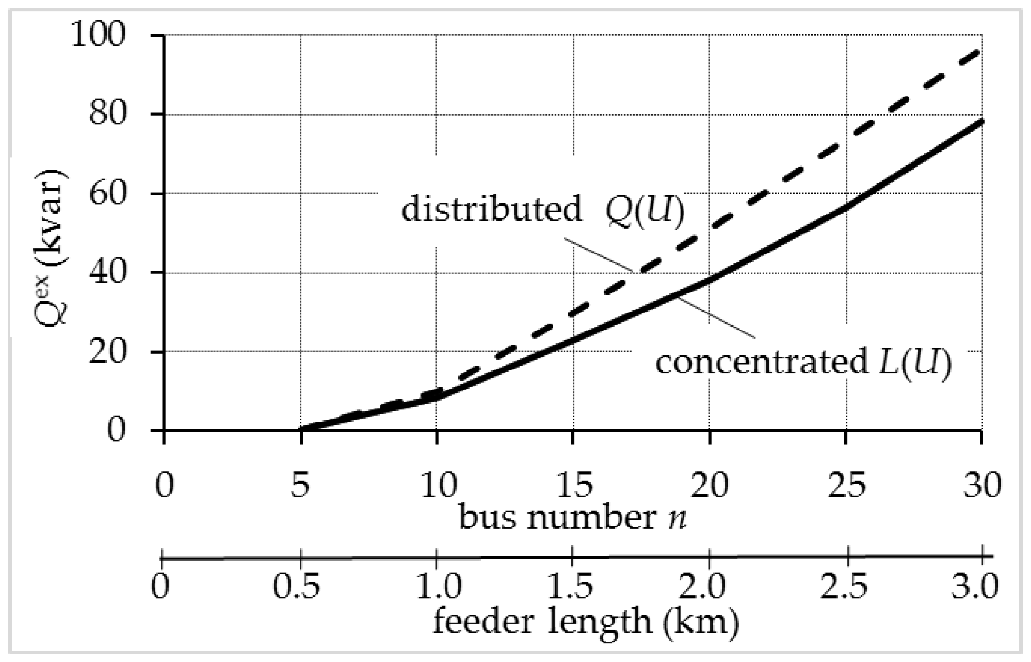
Figure 17 shows the exchanged reactive power as a function of the bus number or feeder length for the distributed Q(U) and concentrated L(U) control strategies. The results show that for feeder lengths from 0.5 km up to 1.0 km, there are not relevant differences between the two control strategies. However, for feeders longer than 1 km, L(U) is much more effective than Q(U). The required Qex to reach the same voltage target at feeder end is by L(U) always smaller than by Q(U). The longer the feeder, the greater the advantages of L(U) versus Q(U).

4. Behavior of Distributed versus Concentrated Local Control Strategy in Different Real Grids

The theoretical investigation and simulations in the LV test feeder made above have clearly shown the advantages of the concentrated versus distributed local control strategy. To find out how these benefits apply to real networks as well, two typical real LVGs were simulated as follows.

4.1. Description of the Real Grids

To see the effects of the various control strategies on a real LVG, two different grid types were selected: urban and rural. Figure 18 depicts the schematics of the different real LVGs. Figure 18a shows a simplified one-line diagram of a typical urban LVG with nine main feeders. The longest feeder is 1.27 km long, while the shortest is 0.305 km long. In this relatively large grid with a 96% cable share, 175 urban residential customers are connected. The LVG is connected to the MVG through a 20 kV/0.4 kV, 630 kVA DTR. Figure 18b presents a simplified one-line diagram of a typical rural LVG with four main feeders. The longest feeder is 1.63 km long, while the shortest is 0.565 km long. In this grid with a 59% cable share, 61 rural residential customers are connected. This LVG is connected to the MVG through a 20 kV/0.4 kV, 160 kVA DTR.
Each prosumer is modeled by means of a ZIP load and a PV facility. The ZIP model is described as follows:
P(U) = P0·(1.2 − 1.17·U + 0.96·U2)
and:
Q(U) = Q0·(4.88 − 10.16·U + 6.28·U2),
where P0 and Q0 are the active and reactive power of the load at nominal conditions.
The PV facilities are modeled with a peak active power production of 5.0 kW and an inverter rating of Sinv-nom = 5.0 ⁄ 0.9 kVA. Inverters are associated with a local control strategy as follows.

4.2. Local Control Strategies

Two types of local control strategies are simulated: distributed and concentrated.

4.2.1. Distributed

Two types of distributed local control strategies are considered:
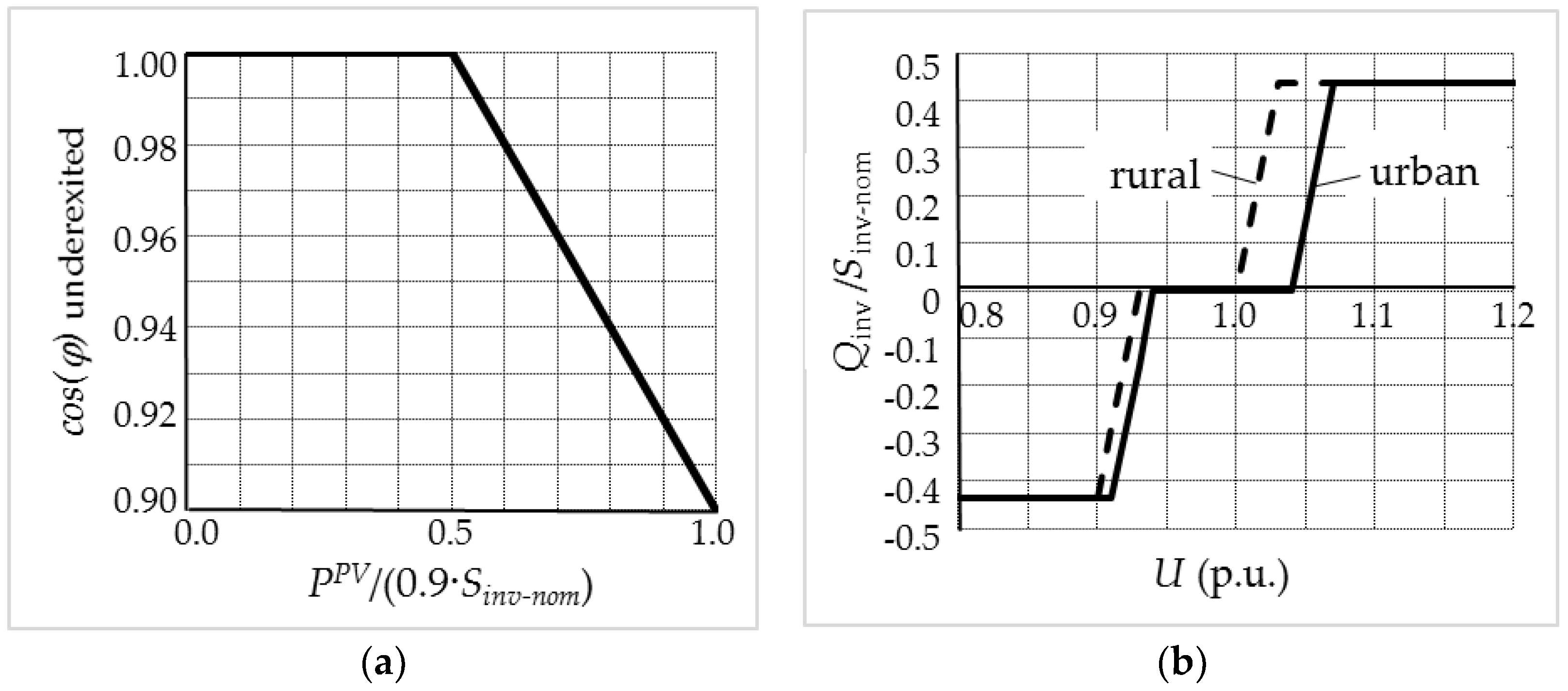
  • cosφ(P)—it is assumed that all of the prosumers have the same weather conditions. That means that all of the prosumers inject the maximal real power with a cos(φ) = 0.9 as given from the inverter characteristic shown in Figure 19a.
  • Q(U)—to reach the best possible results concerning the elimination of voltage violations and minimization of reactive power flow on the grid, two different Q(U)-characteristics are used [25]. Figure 19b depicts the Q(U) characteristics used in urban and rural grids.

4.2.2. Concentrated

The concentrated local strategy is considered by a L(U) control that is set at the end of each violated feeder. L(U)s are simulated by variable inductive devices. The inductance of each inductive device is a function of its local grid voltage; it is switched ON for local voltages ≥ Uset−point.

4.3. Behavior of Concentrated versus Distributed Control Strategy

The operation conditions of a sunny day at 12:00 are simulated for all cases. Therefore, PV facilities connected on both real grids have injected their maximal active power of 5 kW. The urban grid loads have consumed 0.75 kW, while the rural grid ones have consumed 0.685 kW. Loads on both real grids have been simulated with a cos(φ) = 0.95.
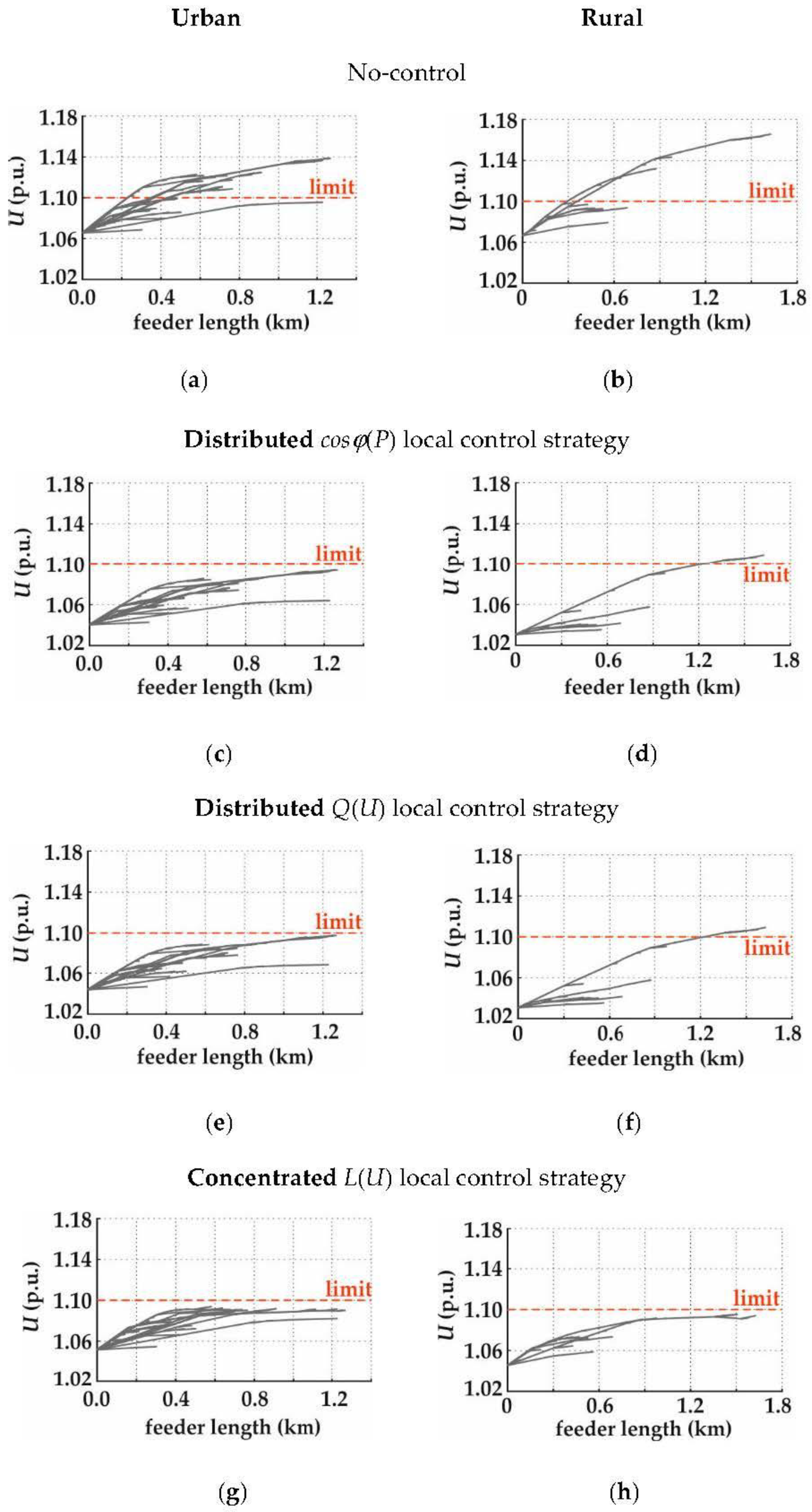
Figure 20 shows an overview of the voltage profiles of two typical real grids, urban and rural, when no-control, distributed cosφ(P), distributed Q(U), and concentrated L(U) local control strategies are exercised. Figure 20a,b correspond to the no-control condition for the urban and rural grid case, respectively. Five feeders in the urban grid case and two feeders in the rural one violate the upper voltage limit. The use of a distributed cosφ(P) or Q(U) local control strategy eliminates all of the voltage limit violations in urban grids, as shown in Figure 20c,e. Meanwhile for rural grids, they do not eliminate all of them, as indicated in Figure 20d,f. In contrast, the concentrated L(U) local control strategy eliminates all of the voltage limit violations for both grids, Figure 20g,h.
Table 2 shows the Qex and the distribution transformer loading for different control strategies. The results show that in both grids, the Qex is higher for the distributed control strategies than for the concentrated one. Transformer loading follows the same trend as Qex, thus being higher for the distributed cosφ(P) or Q(U) than for the concentrated L(U) local control strategy.

5. Impact of the Control Strategies in the Reciprocal Behavior between MVG and LVGs

To study the effects of the distributed versus concentrated local control strategy on the mutual influences between MVG and LVG, simulations are performed in models that combine both grids. The variation of the load consumption and PV production are taken into account by their daily profiles.

5.1. Combined Medium and Low-Voltage Grid Modeling

Figure 21 depicts the schematic of MVG combined with the respective LVGs. The medium-voltage (MV) feeder is 24-km long. It is connected to the high-voltage grid through a 110 kV/20 kV, 18.5 MVA supplying transformer (STR) that has an on-load tap changer (OLTC). The feeder has a cable structure with R’ = 0.206 Ω/km, X’ = 0.122208 Ω/km, and C’ = 254 nF/km. Thirty-two LVGs are connected at equal feeder segment intervals that are each 0.75 km long. The same LVG types and control strategies as described in Section 4.1 and Section 4.2, respectively, are used. The two LVG types are alternately connected to the MV feeder as follows: urban, rural, urban, etc.
Prosumers are modeled by means of a load and injection, as described in Section 4.1. The different load/injection cases are taken into account using the load consumption and PV production profiles shown in Figure 22. The active power, which is normalized to the maximum value reached within 24 h, is located on the ordinate. The maximum load per customer connected to urban or rural LVG is 1.50 kW or 1.37 kW, respectively. In both cases, the maximum value is reached at 20:00. Each PV facility injects the maximum active power of 5 kW at 12:12.

5.2. Impact of Different Control Strategies on the Behavior of MVG

The two local control strategies discussed above, both distributed and concentrated, provoke additional reactive power flows in LVGs to limit the voltages. These additional reactive power flows, which are provided to LVGs via the MVG, affect the voltages of the latter. In the following section, the effect of the DTR connection point on the Qex and their influence on the voltage profile of MV feeders is analyzed for the different control strategies.

5.2.1. Influence of the DTR Connection Point on Qex

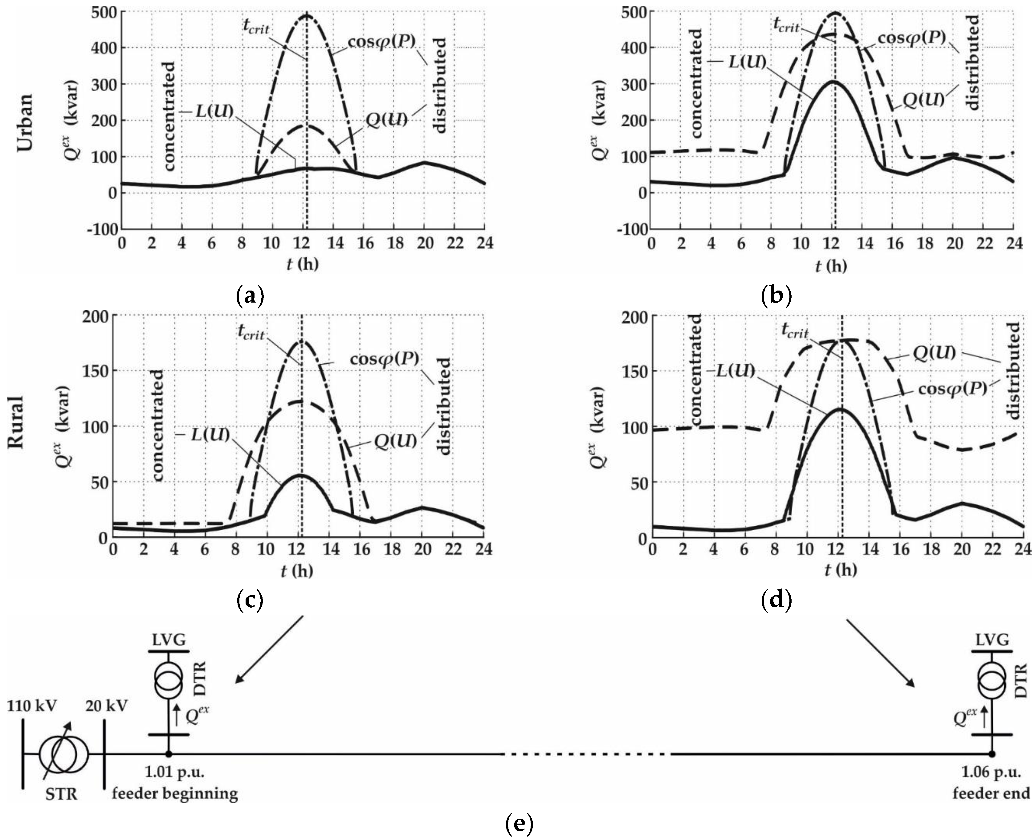
LVGs are connected via DTRs to various points along the MV feeder. As known, the voltage varies along the feeder from bus to bus, and additionally, it changes in each bus depending on the power flows throughout the day. Since the DTRs have fixed taps, the MV feeder voltage changes are forwarded directly to the LVG via the transformer ratio. This means that voltage changes on the MVG directly affect the voltage at the LVGs, and thus also directly affect the operating points of the controllers and the Qex. Figure 23 shows the daily Qex for different control strategies and various LVGs connected to the MV feeder. To understand the influence of the DTR connection point on the Qex, two connection points are selected: the first at the feeder beginning, and the second at the feeder end, as shown in Figure 23e. Due to the feedback active power supply from low to medium and then to the high-voltage grid, the voltage at the end is higher than at the beginning of the MV feeder. Thus, the voltage at the beginning of the feeder is assumed as 1.01 p.u., while at the end, it is assumed as 1.06 p.u. Power flow simulations are performed on both LVGs as described in Section 4.1 by sequentially setting the two different voltages on the slack bus—i.e., the 20-kV bus of the DTRs. Figure 23a,b correspond to the daily Qex for the urban LVG connected at the beginning and end of the feeder, respectively, and when distributed cosφ(P), distributed Q(U), or concentrated L(U) local control strategy is exercised. Simulation results for the rural grid are shown in Figure 23c,d. Qex consists of the reactive power of load and loss as well as the additional reactive power produced by different voltage control strategies. The reactive power of load and loss depends on the voltage, but this dependence is barely visible in the figures due to the large Qex scale. The dependence of the additional reactive power on voltage is determined by the control strategy used. The reactive power produced in case of the cosφ(P) control, Q i n v c o s φ ( P ) , is independent of the voltage. Q i n v c o s φ ( P ) is present at the same period 08:50–15:30 in all of the cases, as shown in Figure 23a–d. The distributed cosφ(P) control is active in accordance with its characteristic, as shown in Figure 19a. Unlike this case, the additional reactive power flow provoked by exercising the distributed Q(U) control strategy, Q i n v Q ( U ) , strongly depends on voltage at the DTR’s connection point. The Q(U) control may be active even in periods without solar irradiation as long as its local voltage in LVG is outside the dead band of the control characteristic, as shown in Figure 19b. This case is clearly visible in periods 00:00–07:30 and 17:00–24:00 in Figure 23b; 00:00–07:30 in Figure 23c; and 00:00–07:30 and 17:00–24:00 in Figure 23d, where Qex is larger than in the cosφ(P) case. In all of the cases, the maximum provoked Qex is reached at the critical time, tcrit. Around this time, the cosφ(P) control provokes a much larger Qex than the Q(U) control for the urban and rural LVG when the DTRs are connected at the feeder beginning, as shown in Figure 23a,c. When the DTRs are connected at the feeder end, the difference of Qex is smaller in the urban LVG case, as shown in Figure 23b, and it becomes almost zero in the rural LVG case, as seen in Figure 23d. As shown in Figure 23a–d, the concentrated L(U) local control strategy causes the smallest Qex in all of the cases. Qex depends on voltage at the DTR’s connection point, because the L(U) control is active as long as its local voltage in LVG exceeds the Uset-point. In summary, regardless of the connection point of the DTRs at the MV feeder and the daily load consumption and PV production profiles, the use of a concentrated local control strategy in LVGs causes less Qex than the distributed strategies.
The effect of the Qex provoked by the various control strategies on the voltage profile of the MV feeder is analyzed below.

5.2.2. Influence of the Concentrated versus Distributed Control Strategy on the Voltage Profile in MVG

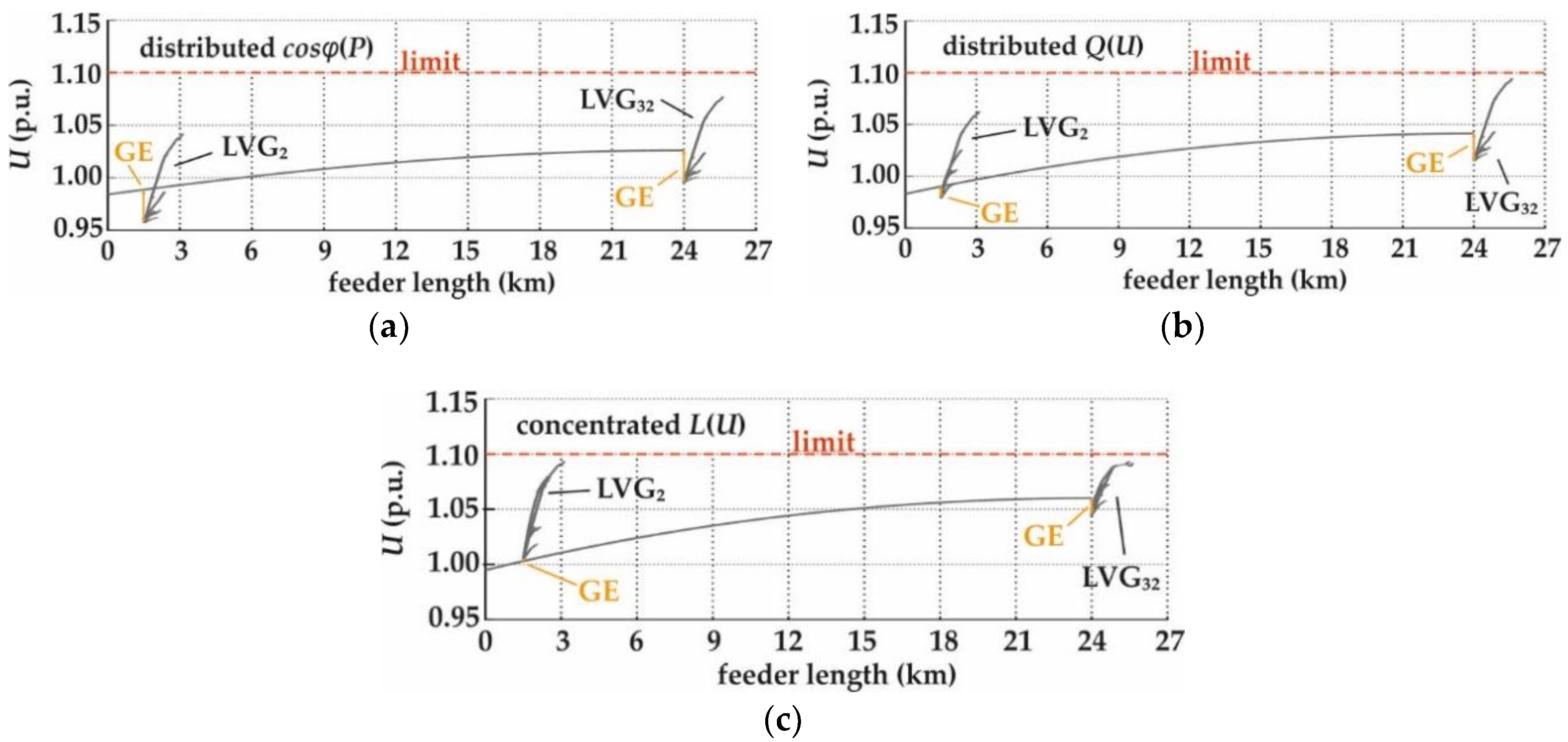
The influence of the concentrated versus distributed control strategy on the voltage profile in MVG is analyzed by means of power flow simulations at tcrit. The STR’s high-voltage bus is selected as a slack bus with a voltage of 1.01 p.u. Figure 24 depicts the voltage profiles of the MV feeder and of the second and 32nd LVGs for different control strategies at tcrit = 12:12. Figure 24a–c show the voltage profiles for the distributed cosφ(P) and Q(U) controls, and concentrated L(U), respectively. As expected, the concentrated L(U) control strategy provokes the smallest reactive power exchange through the STR, Q S T R e x , as shown in Table 3. Therefore, the corresponding voltage profiles are less suppressed than in the both cases of the distributed control strategy, where the voltage profiles are pushed down more than is needed. In the DTR level, the global effect (GE) provoked by Qex is present in all of the cases. GE is the voltage displacement on the transformer buses provoked by the reactive power injection in radial structures [26]. The Q S T R e x , OLTC position change, and the GE for different control strategies used in real LVGs are summarized in Table 3. In the case of the concentrated strategy, GE is smaller than in the distributed control strategies. The distributed cosφ(P) has the worst performance. It provokes not only the largest Q S T R e x and GEs, but it also causes an OLTC position change from 13 to 15.
In summary, the effects of the concentrated local control strategy in MVG behavior are more favorable than those of the distributed strategies.

6. Conclusions

According to the reported simulation results, the following conclusions are delivered. For feeder lengths from 0.5 km up to 1.0 km, there are not relevant differences between the two control strategies. However, for feeders longer than 1 km, the concentrated Volt/var local control strategy (e.g., L(U)) shows clear advantages versus the distributed one (e.g., cosφ(P) or Q(U)). By use of L(U), the required Qex to reach the same voltage target at the feeder end, and the distribution transformer loading are always smaller than by use of Q(U). The longer the feeder, the greater the advantages of a concentrated versus distributed control strategy. Even in rural grids with the longest feeders, where the distributed Volt/var local control strategies do not eliminate all of the violations of upper voltage limit, the concentrated Volt/var local control strategy successfully eliminates all of the voltage violations. Therefore, the latter increases the PV hosting capacities of the feeders, regardless of their length. Simulations in a combined medium and low-voltage grid model have shown that the effects of the concentrated local control strategy in MVG behavior are more favorable than those of the distributed strategies. However, a practical implementation of the concentrated Volt/var local control strategy in the context of smart grids with a high DG share would validate the relevance of these outcomes.

Author Contributions

Data curation, C.S.; Software, D.-L.S.; Writing—original draft, A.I.

Funding

This research received no external funding.

Acknowledgments

The authors acknowledge the TU Wien University Library for financial support through its Open Access Funding Program.

Conflicts of Interest

The authors declare no conflict of interest.

Appendix A

The list of the first four terms of (10) follows:
● First term
As in (6)
Figure A1. Equivalent circuit of the first term of (10).
Applsci 08 01382 g0a1
Δ U 1 = Δ U Σ ( 1 ) = Q · X U 1 .
● Second term
As in (6)
Figure A2. Equivalent circuit of the second term of (10).
Applsci 08 01382 g0a2
Δ U 2 = 2 · Q · X U 2 .
Combining (1) and (A1)
U 2 = U 1 Δ U 1 = U 1 + Q · X U 1 ,
Δ U Σ ( 2 ) = Δ U 1 + Δ U 2 ,
Δ U Σ ( 2 ) = Q · X U 1 2 · Q · X U 1 + Q · X U 1 .
● Third term
Figure A3. Equivalent circuit of the third term of (10).
Applsci 08 01382 g0a3
Figure A4. Equivalent circuit of the fourth term of (10).
Applsci 08 01382 g0a4
Δ U Σ ( 3 ) = Δ U 1 + Δ U 2 + Δ U 3 ,
Δ U Σ ( 3 ) = Q · X U 1 2 · Q · X U 1 + Q · X U 1 3 · Q · X U 1 + Q · X U 1 + 2 · Q · X U 1 + Q · X U 1 .
● Fourth term
Δ U Σ ( 4 ) = Δ U 1 + Δ U 2 + Δ U 3 + Δ U 4 ,
Δ U Σ ( 4 ) = Q · X U 1 2 · Q · X U 1 + Q · X U 1 3 · Q · X U 1 + Q · X U 1 + 2 · Q · X U 1 + Q · X U 1 4 · Q · X U 1 + Q · X U 1 + 2 · Q · X U 1 + Q · X U 1 + 3 · Q · X U 1 + Q · X U 1 + 2 · Q · X U 1 + Q · X U 1 .

References

  1. Witzmann, R.; Esslinger, P.; Grass, N.; Girstl, S.; Keck, R.; Adelmann, A. Improving power quality and capacity in low voltage grids with decentral power generation using intelligent inverters. In Proceedings of the IETG Congress, Würzburg, Germany, 8–9 November 2011. [Google Scholar]
  2. Bertani, A.; Borghetti, A.; Bossi, C.; de Biase, L.; Lamquet, O.; Massucco, S.; Morini, A.; Nucci, C.A.; Paolone, M.; Quaia, E.; et al. Management of low voltage grids with high penetration of distributed generation: Concepts, implementations and experiments. In Proceedings of the CIGRE Session, Paris, France, 27 August–1 September 2006; pp. 1–13. [Google Scholar]
  3. Taljan, G.; Krasnitzer, M.; Strempfl, F.; Jarz, A. Spannungsregelung im 30 kV Netz UW Judenburg/West Lösungsansätze mit Smart Grids. In Proceedings of the Symposium Energieinnovation, Graz, Austria, 15–17 February 2012. [Google Scholar]
  4. Procházka, K.; Vaculík, P.; Kysnar, F.; Novotny, J.; Mezera, D. Voltage quality and reactive power flow solution in distribution networks with a high share of renewable energy sources. In Proceedings of the CIRED, Stockholm, Sweden, 10–13 June 2013; pp. 1–5. [Google Scholar]
  5. Elbs, C. Netzeinsparungsmöglichkeiten und Erfahrungen einer realen Q(U)-Einführung bei PV Wechselrichtern im Bundesland. In Proceedings of the Smart Grid Week, Graz, Austria, 19–23 May 2014. [Google Scholar]
  6. Turitsyn, K.; Sulc, P.; Backhaus, S.; Chertkov, M. Options for control of reactive power by distributed photovoltaic generators. Proc. IEEE 2011, 99, 1063–1073. [Google Scholar] [CrossRef]
  7. Malekpour, A.R.; Pahwa, A. Reactive Power and Voltage Control in Distribution Systems with Photovoltaic Generation; North American Power Symposium (NAPS): Champaign, IL, USA, 2012; pp. 1–6. [Google Scholar]
  8. Bollen, M.H.J.; Sannino, A. Voltage control with inverter-based distributed generation. IEEE Trans. Power Deliv. 2005, 20, 519–520. [Google Scholar] [CrossRef]
  9. Bolognani, S.; Zampieri, S. A distributed control strategy for reactive power compensation in smart Microgrids. IEEE Trans. Autom. Control 2013, 58, 2818–2833. [Google Scholar] [CrossRef]
  10. Caldon, R.; Coppo, M.; Turri, R. Distributed voltage control strategy for LV networks with inverter-interfaced generators. Electr. Power Syst. Res. 2014, 107, 85–92. [Google Scholar] [CrossRef]
  11. Neal, R. The of AMI meters and solar PV inverters in advanced Volt/var control system on a distributed circuit. In Proceedings of the IEEE PES Transmission and Distribution Conference and Exposition, New Orleans, LA, USA, 19–22 April 2010; pp. 1–4. [Google Scholar]
  12. Guideline for Generating Plants’ Connection to and Parallel Operation with the Medium-Voltage Network. Available online: http://electrical-engineering-portal.com/res2/Generating-Plants-Connected-to-the-Medium-Voltage-Network.pdf (accessed on 23 July 2018).
  13. IEEE Standard for Interconnection and Interoperability of Distributed Energy Resources with Associated Electric Power Systems Interfaces; IEEE Std 1547-2018 (Revision of IEEE Std 1547-2003); IEEE: Piscataway, NJ, USA, 2018; pp. 1–138. [CrossRef]
  14. Demirok, E.; González, P.C.; Frederiksen, K.H.B.; Sera, D.; Rodriguez, P.; Teodorescu, R. Local reactive power control methods for overvoltage prevention of distributed solar inverters in low-voltage grids. IEEE J. Photovol. 2011, 1, 174–182. [Google Scholar] [CrossRef]
  15. Smith, J.W.; Sunderman, W.; Dugan, R.; Seal, B. Smart inverter volt/var control functions for high penetration of PV on distribution systems. In Proceedings of the IEEE/PES Power Systems Conference and Exposition, Phoenix, AZ, USA, 20–23 March 2011; pp. 1–6. [Google Scholar]
  16. Zhang, F.; Guo, X.; Chang, X.; Fan, G.; Chen, L.; Wang, Q.; Tang, Y.; Dai, J. The reactive power voltage control strategy of PV systems in low-voltage string lines. In Proceedings of the IEEE Manchester PowerTech, Manchester, UK, 18–22 June 2017; pp. 1–6. [Google Scholar]
  17. Winter, C.; Schwalbe, R.; Heidl, M.; Prüggler, W. Harnessing PV inverter controls for increased hosting capacities of smart low voltage grids: Recent results from Austrian research and demonstration projects. In Proceedings of the 4th International Workshop on Integration of Solar Power into Power Systems, Berlin, Germany, 10–11 November 2014. [Google Scholar]
  18. Karthikeyan, N.; Pokhrel, B.R.; Pillai, J.R.; Bak-Jensen, B. Coordinated voltage control of distributed PV inverters for voltage regulation in low voltage distribution networks. In Proceedings of the IEEE PES Innovative Smart Grid Technol. Conf. Europe (ISGT-Europe), Torino, Italy, 26–29 September 2017; pp. 1–6. [Google Scholar]
  19. Demirok, E.; Gonzalez, P.C.; Fredriksen, K.H.B.; Sera, D.; Rodriguez, P.; Teodorecu, R. Local reactive power control methods for overvoltage prevention of distributed solar inverters in low-voltage grids. IEEE J. Photovolt. 2011, 1, 174–182. [Google Scholar] [CrossRef]
  20. Jahangiri, P.; Aliprantis, D.C. Distributed volt/var control by PV inverters. IEEE Trans. Power Syst. 2013, 28, 3429–3439. [Google Scholar] [CrossRef]
  21. Marggraf, O.; Laudahn, S.; Engel, B.; Lindner, M.; Aigner, C.; Witzmann, R.; Schoeneberger, M.; Patzack, S.; Vennegeerts, H.; Cremer, M.; et al. U-Control—Analysis of distributed and automated voltage control in current and future distribution grids. In Proceedings of the International ETG Congress, Bonn, Germany, 28–29 November 2017; pp. 1–6. [Google Scholar]
  22. Hashemi, S.; Østergaard, J. Methods and strategies for overvoltage prevention in low voltage distribution systems with PV. IET Renew. Power Gener. 2017, 11, 205–214. [Google Scholar] [CrossRef] [Green Version]
  23. Bletterie, B.; Kadam, S.; Bolgaryn, R.; Zegers, A. Voltage control with PV inverters in low voltage networks—In depth analysis of different concepts and parameterization criteria. IEEE Trans. Power Syst. 2017, 32, 177–185. [Google Scholar] [CrossRef]
  24. Schultis, D.-L.; Ilo, A.; Schirmer, C. Evaluation of different local var control strategies in low voltage grids. In Proceedings of the CIRED Workshop, Ljubljana, Slovenia, 7–8 June 2018; pp. 1–4. [Google Scholar]
  25. Schultis, D.-L.; Ilo, A.; Schirmer, C. Overall performance evaluation of reactive power control strategies in low voltage grids with high prosumer share. Electr. Power Syst. Res. 2018. under review. [Google Scholar]
  26. Ilo, A. Effects of the reactive power injection on the grid-The rise of the Volt/var interaction chain. Smart Grid Renew. Energy 2016, 7, 217–232. [Google Scholar] [CrossRef]
Figure 1. Overview of the distributed Q(U) local control strategy or rather distributed var-sinks.
Applsci 08 01382 g001
Figure 2. Overview of the concentrated L(U) local control strategy or rather concentrated var-sink.
Applsci 08 01382 g002
Figure 3. Overview of a feeder segment with back-up active power supply: (a) Equivalent circuit; (b) Phasor diagram.
Applsci 08 01382 g003
Figure 4. Equivalent circuit of a low-voltage (LV) feeder with distributed var-sinks.
Applsci 08 01382 g004
Figure 5. Equivalent circuit of a LV feeder with a concentrated var-sink.
Applsci 08 01382 g005
Figure 6. The theoretical exchanged reactive power as a function of the bus number for the distributed and concentrated var-sink cases.
Applsci 08 01382 g006
Figure 7. The theoretical voltage drop amplitude in every feeder segment as a function of the bus number for the distributed and concentrated var-sink cases.
Applsci 08 01382 g007
Figure 8. The theoretical voltage profile for the distributed and concentrated var-sink cases.
Applsci 08 01382 g008
Figure 9. The impact of the distributed and concentrated var-sink cases on voltage profile.
Applsci 08 01382 g009
Figure 10. Equivalent circuit of an LV feeder where the distributed Q(U) or concentrated L(U) local control strategies can be applied.
Applsci 08 01382 g010
Figure 11. Schematic presentation of the power flows when Q(U) is applied: (a) the active and reactive power flows supplied by the PV inverters; (b) Q(U) characteristic set by all of the inverters.
Applsci 08 01382 g011
Figure 12. Schematic presentation of the active and reactive power flows when L(U) is applied.
Applsci 08 01382 g012
Figure 13. Voltage profiles for different control strategies: No control (inverters inject with cos(φ) = 1), distributed Q(U) and concentrated L(U) control.
Applsci 08 01382 g013
Figure 14. The particular impact of the injected active power, the absorbed reactive power caused by the different control strategies, and the impact of their combination on the shape of the voltage profile.
Applsci 08 01382 g014
Figure 15. The amplitude of voltage drop in every feeder segment caused by distributed active power, an injection of PV facilities, Pinv, distributed Q(U), and concentrated L(U) control strategies.
Applsci 08 01382 g015
Figure 16. The consumed reactive power and the Qex flows for the Q(U) and L(U) control strategies.
Applsci 08 01382 g016
Figure 17. Exchanged reactive power as a function of the bus number or feeder length for the Q(U) and L(U) control strategies.
Applsci 08 01382 g017
Figure 18. Schematic presentation of different real low-voltage grids (LVGs): (a) urban and (b) rural.
Applsci 08 01382 g018
Figure 19. Different inverter control characteristics: (a) cosφ(P) and (b) Q(U).
Applsci 08 01382 g019
Figure 20. Overview of voltage profiles of two typical real grids, urban and rural, when no-control, distributed cosφ(P), distributed Q(U), and concentrated L(U) local control strategies are exercised.
Applsci 08 01382 g020
Figure 21. Schematic representation of a medium-voltage grid (MVG) combined with the respective LVGs.
Applsci 08 01382 g021
Figure 22. Load consumption and PV production profiles.
Applsci 08 01382 g022
Figure 23. Daily Qex for different control strategies and various LVGs connected at the MV feeder: (a) urban, connected at the feeder beginning; (b) urban, connected at the feeder end; (c) rural, connected at the beginning; (d) rural connected at the end; (e) overview of the MVG.
Applsci 08 01382 g023
Figure 24. Voltage profiles of the MV feeder and of the second and 32nd LVGs for different control strategies at tcrit = 12:12: (a) cosφ(P); (b) Q(U); and (c) L(U).
Applsci 08 01382 g024
Table 1. Reactive power consumption, loss, and exchange for different control strategies in the LV test grid.
ΣQinv or Qc (kvar)Q-Loss (kvar)Qex (kvar)
distributed Q(U)34.5216.5551.07
concentrated L(U)22.7715.2938.06
Table 2. Reactive power consumption, loss, and exchange for different control strategies in real LVGs.
DistributedConcentrated
cosφ(P)Q(U)L(U)
Qex (kvar)TrL (%)Qex (kvar)TrL (%)Qex (kvar)TrL (%)
Urban491.68130.00436.03125.11305.02114.52
Rural176.44181.65176.44181.65115.15158.38
Table 3. Reactive power exchange through supplying transformer (STR), on-load tap changer (OLTC) position change, and the global effect in distribution transformers (DTR) level for different control strategies in real low-voltage grids (LVGs).
Q S T R e x ( Mvar ) OLTC Position ChangeGE (p.u)
DTR2DTR32
distributedcosφ(P)11.49313→15−0.0318−0.0305
Q(U)8.118none−0.0113−0.0267
concentratedL(U)5.452none+0.0014−0.0151