Review of Rock-Mass Rating and Tunneling Quality Index Systems for Tunnel Design: Development, Refinement, Application and Limitation

Abstract
:1. Introduction
2. RMR and Q System Establishment
2.1. Development of the RMR System
2.2. Development of the Q System
3. Modification of the RMR and Q Systems Since Their Establishment
3.1. Modification in Terms of Characterization
3.1.1. RMR System
3.1.2. Q System
3.2. Development in Terms of Support
3.2.1. RMR System
3.2.2. Q System
4. Application in Determination of Rock-Mass Properties
4.1. Deformation Modulus of Rock Masses
4.2. Strength of Rock Masses
4.3. Poisson’s Ratio Value
4.4. Mohr-Coulomb Parameters
4.5. Hoek-Brown Constants and Tensile Strength of Rock Mass
5. Other Applications
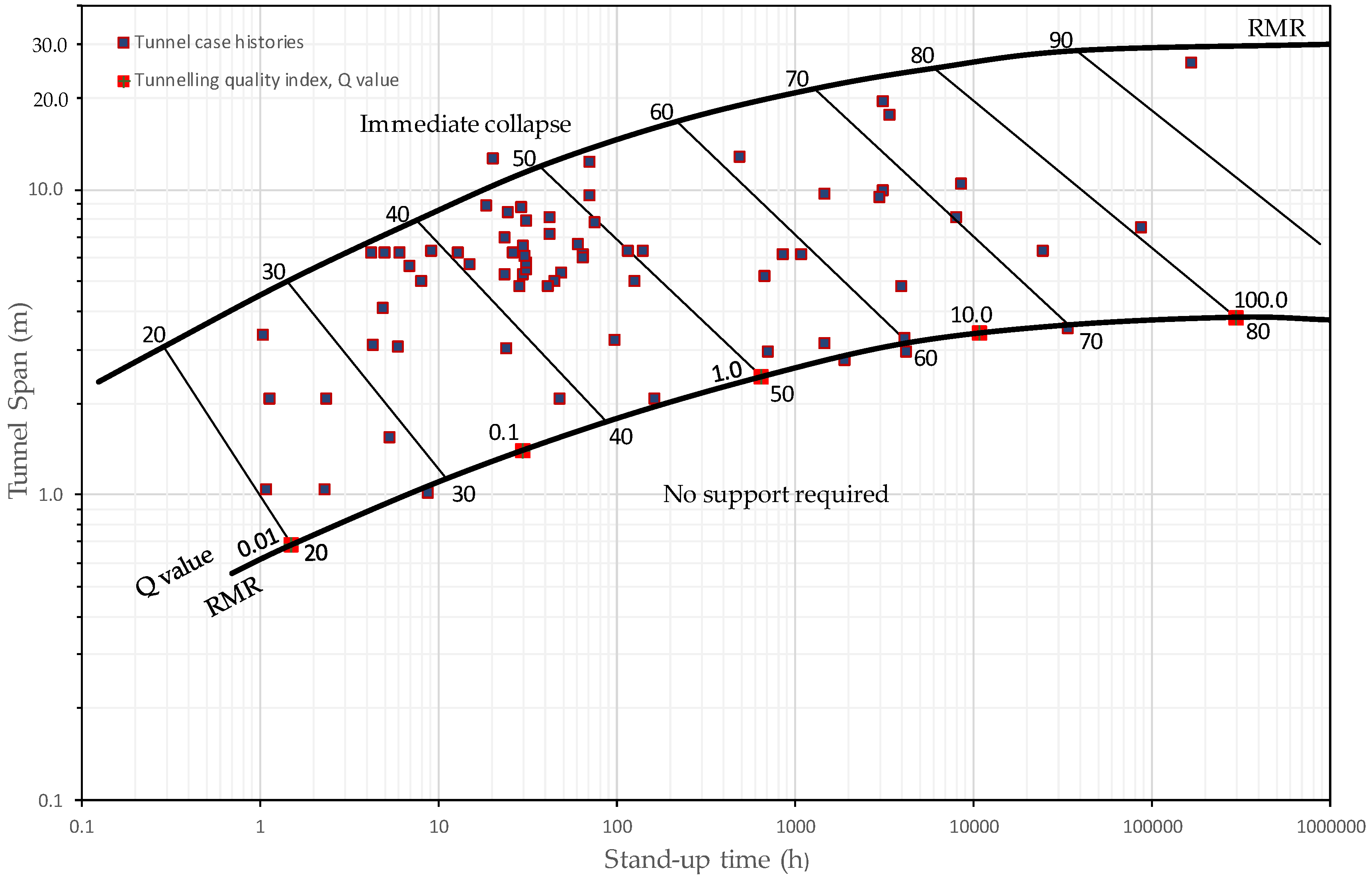
5.1. Stand-Up Time
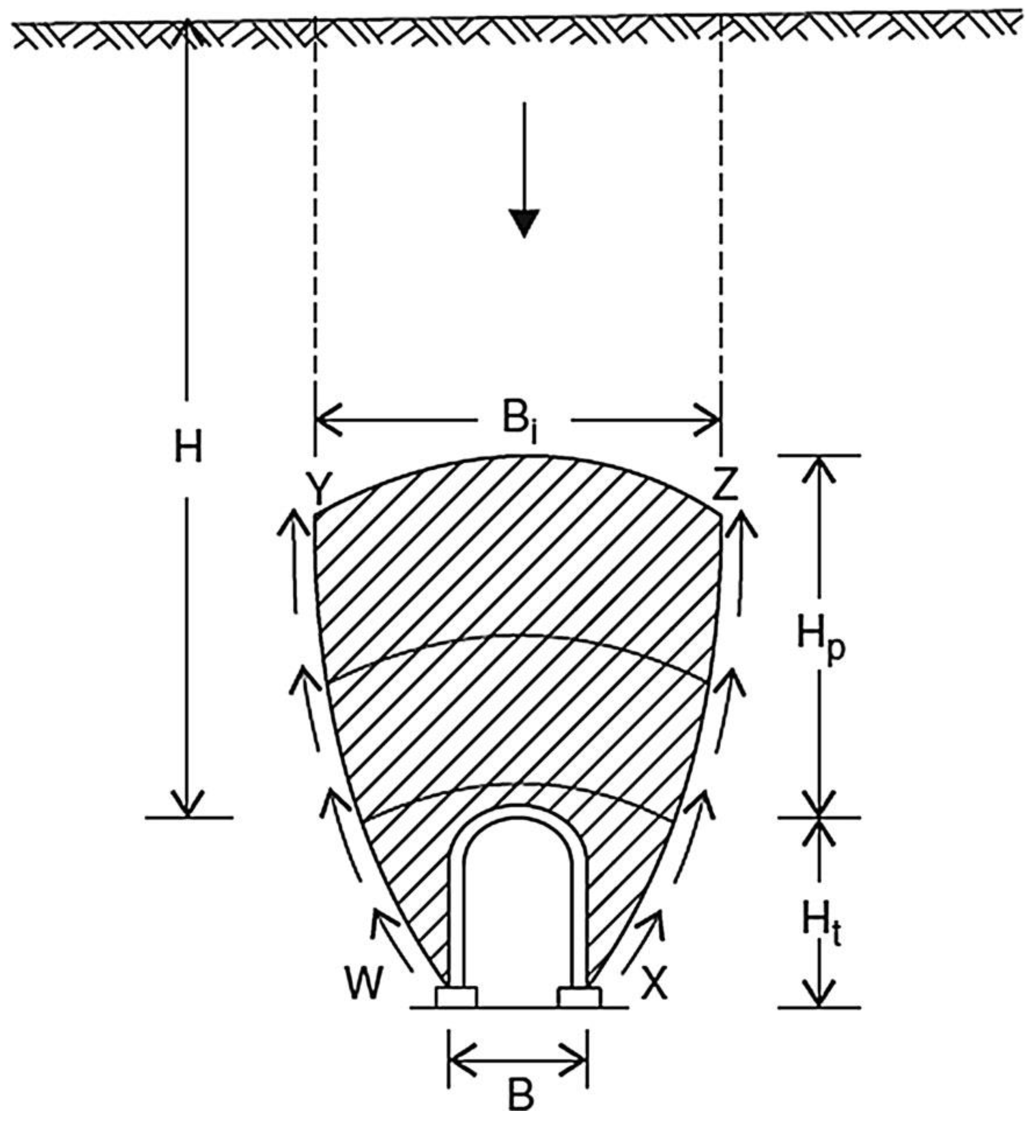
5.2. Rock Load
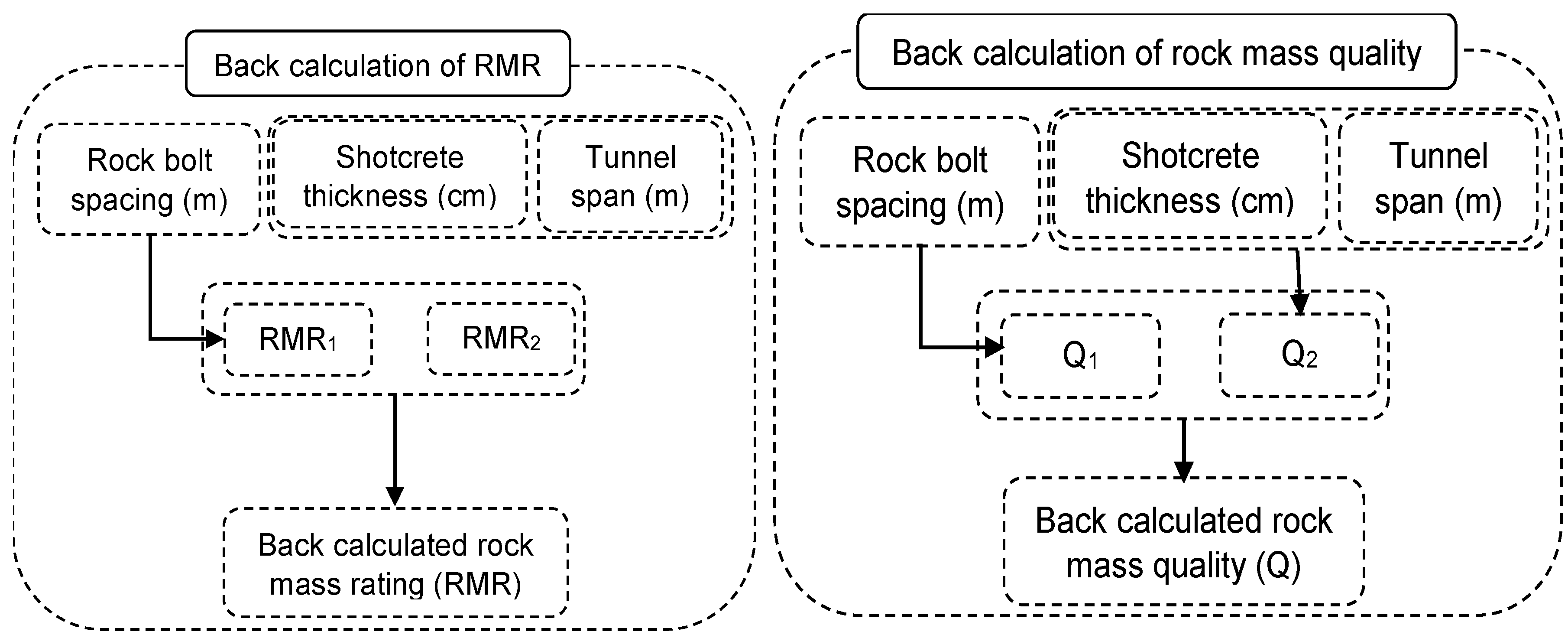
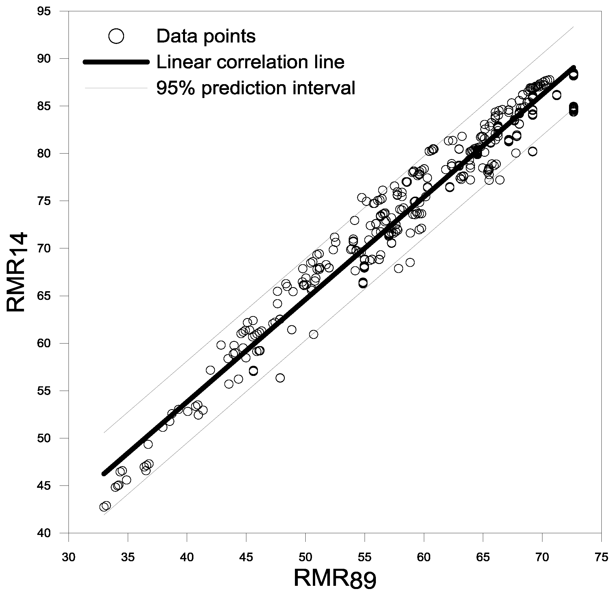
6. Recommended Procedure for Using RMR and Q Systems and their Correlation
- Use standard procedure of measurement for the parameters instead of only description.
- Determine the ranges and average values of RMR and Q per their classification procedure.
- Use RMR and Q systems and check them with published correlation.
- Estimate the support and rock-reinforcement requirements.
- For preliminary modelling, determine the stand-up time and modulus of rock-mass.
- For checking, perform numerical modelling.
- If the available information is inadequate, extend the exploration work.
- Consider the construction process.
- Include the characterization information of rock-mass along with the design procedure, specifications and assumptions in the Geotechnical Baseline Report.
- In the construction phase, calculate RMR and Q for design verification and modification.
7. Limitations of RMR and Q Systems
7.1. Limitations Related to RMR System
7.2. Limitations Related to Q System
7.3. Limitations Related to the Two Systems
8. Conclusions
Author Contributions
Funding
Acknowledgments
Conflicts of Interest
References
- Stille, H.; Palmström, A. Ground behaviour and rock mass composition in underground excavations. Tunn. Undergr. Space Technol. 2008, 23, 46–64. [Google Scholar] [CrossRef]
- Harrison, J.; Hudson, J.; Popescu, M.E. Engineering Rock Mechanics: Part 2. Illustrative Worked Examples. Appl. Mech. Rev. 2000, 55, B30. [Google Scholar] [CrossRef]
- Pinheiro, M.; Emery, X.; Miranda, T.; Lamas, L.; Espada, M. Modelling Geotechnical Heterogeneities Using Geostatistical Simulation and Finite Differences Analysis. Minerals 2018, 8, 52. [Google Scholar] [CrossRef]
- Feng, X.-T.; Hudson, J.A. Rock Engineering Design; CRC Press: Boca Raton, FL, USA, 2011. [Google Scholar]
- Terzaghi, K. Rock Defects and Loads on Tunnel Supports; Harvard University: Cambridge, MA, USA, 1946. [Google Scholar]
- Shen, Y.; Yan, R.; Yang, G.; Xu, G.; Wang, S. Comparisons of Evaluation Factors and Application Effects of the New [BQ] GSI System with International Rock Mass Classification Systems. Geotech. Geol. Eng. 2017, 35, 2523–2548. [Google Scholar]
- Aydan, Ö.; Ulusay, R.; Tokashiki, N. A new rock mass quality rating system: Rock mass quality rating (RMQR) and its application to the estimation of geomechanical characteristics of rock masses. Rock Mech. Rock Eng. 2014, 47, 1255–1276. [Google Scholar] [CrossRef]
- Bieniawski, Z. Engineering classification of jointed rock masses. Civil Eng. S. Afr. 1973, 15, 333–343. [Google Scholar]
- Barton, N.; Lien, R.; Lunde, J. Engineering classification of rock masses for the design of tunnel support. Rock Mech. 1974, 6, 189–236. [Google Scholar] [CrossRef]
- Romana, M.; Serón, J.B.; Montalar, E. SMR Geomechanics classification: Application, experience and validation. In Proceedings of the 10th ISRM Congress, Sandton, South Africa, 8–12 September 2003. [Google Scholar]
- Palmstrom, A. RMi—A Rock Mass Characterization System for Rock Engineering Purposes. Ph.D. Thesis, University of Oslo, Oslo, Norway, 1995. [Google Scholar]
- Hoek, E.; Kaiser, P.K.; Bawden, W.F. Support of Underground Excavations in Hard Rock; CRC Press: Boca Raton, FL, USA, 2000. [Google Scholar]
- Lauffer, H. Gebirgsklassifizierung fur den Stol Lenbau. Geol. Bauwes. 1958, 24, 46–51. [Google Scholar]
- Deere, D.U. Technical description of rock cores for engineering purpose. Rock Mech. Eng. Geol. 1964, 1, 17–22. [Google Scholar]
- Deere, D.U.; Miller, R. Engineering Classification and Index Properties for Intact Rock; Department of Civil and Environmental Engineering, University of Illinois: Urbana, IL, USA, 1966. [Google Scholar]
- Wickham, G.; Tiedemann, H.; Skinner, E.H. Support determinations based on geologic predictions. In Proceedings of the North American Rapid Excavation and Tunneling Conference, Chicago, IL, USA, 5–7 June 1972. [Google Scholar]
- Barton, N. TBM perfomance estimation in rock using QTBM. Tunn. Tunn. Int. 1999, 30–34. [Google Scholar]
- Şen, Z.; Sadagah, B.H. Modified rock mass classification system by continuous rating. Eng. Geol. 2003, 67, 269–280. [Google Scholar] [CrossRef]
- Von Preinl, Z.B.; Tamames, B.C.; Fernández, J.G.; Hernández, M.Á. Rock mass excavability indicator: New way to selecting the optimum tunnel construction method. Tunn. Undergr. Space Technol. 2006, 3, 237. [Google Scholar] [CrossRef]
- Stille, H.; Palmström, A. Classification as a tool in rock engineering. Tunn. Undergr. Space Technol. 2003, 18, 331–345. [Google Scholar] [CrossRef]
- Beniawski, Z. Tunnel design by rock mass classifications; Army Engineer Waterways Experiment Station: Vicksburg, MS, USA, 1990. [Google Scholar]
- Bieniawski, Z.T. Engineering Rock Mass Classifications: A Complete Manual for Engineers and Geologists in Mining, Civil and Petroleum Engineering; John Wiley & Sons: Hoboken, NJ, USA, 1989. [Google Scholar]
- Celada, B.; Tardáguila, I.; Varona, P.; Rodríguez, A.; Bieniawski, Z. Innovating Tunnel Design by an Improved Experience-Based RMR System. In Proceedings of the World Tunnel Congress, Foz do Iguaçu, Brazil, 9–15 May 2014; p. 9. [Google Scholar]
- Barton, N. Some new Q-value correlations to assist in site characterisation and tunnel design. Int. J. Rock Mech. Min. Sci. 2002, 39, 185–216. [Google Scholar] [CrossRef]
- NGI. The Q-system, Rock Mass Classification and Support Design. Available online: https://www.ngi.no/eng/Publications-and-library/Books/Q-system (accessed on 26 July 2018).
- Laubscher, D. Geomechanics classification of jointed rock masses-mining applications. Trans. Inst. Min. Metall. 1977, 86, A1–A8. [Google Scholar]
- Laubscher, D. Design aspects and effectiveness of support systems in different mining conditions. Inst. Min. Metall. Trans. 1984, 93, A70–A81. [Google Scholar]
- Laubscher, D.; Page, C. The design of rock support in high stress or weak rock environments. In Proceedings of the 92nd Annual General Meeting of the Canadian Institute of Mining and Metallurgy, Ottawa, ON, Canada; 1990. [Google Scholar]
- Ghose, A.K.; Raju, N. Characterization of rock mass vis-à-vis application of rock bolting in Indian coal measures. In Proceedings of the 22nd US Symposium on Rock Mechanics, Cambridge, MA, USA, 29 June–2 July 1981; pp. 422–427. [Google Scholar]
- Unal, E. Modified rock mass classification: M-RMR system. Milest. Rock Eng. 1996. [Google Scholar]
- Liu, Z.-X.; Dang, W.-G. Rock quality classification and stability evaluation of undersea deposit based on M-IRMR. Tunn. Undergr. Space Technol. 2014, 40, 95–101. [Google Scholar] [CrossRef]
- Newman, D.; Bieniawski, Z. A Modified Version of the Geomechanics Classification for Entry Design in Underground Coal Mines; Society of Mining Engineers of AIME: Littleton, CO, USA, 1985. [Google Scholar]
- Romana, M. New adjustment ratings for application of Bieniawski classification to slopes. In Proceedings of the International Symposium on Role of Rock Mechanics, Zacatecas, Mexico, 2–4 September 1985; pp. 49–53. [Google Scholar]
- Tomás, R.; Delgado, J.; Serón, J. Modification of slope mass rating (SMR) by continuous functions. Int. J. Rock Mech. Min. Sci. 2007, 44, 1062–1069. [Google Scholar] [CrossRef]
- Tomas, R.; Cuenca, A.; Cano, M.; García-Barba, J. A graphical approach for slope mass rating (SMR). Eng. Geol. 2012, 124, 67–76. [Google Scholar] [CrossRef]
- Taheri, A.; TAHERI, A.; Tani, K. A Modified rock mass classification system for preliminary design of rock slopes. In Proceedings of the 4th Asian Rock Mechanics Symposium, Singapore, 8–10 November 2006. [Google Scholar]
- Taheri, A. A rating system for preliminary design of rock slopes. In Proceedings of the 41st Japan Geotechnical Society Conference (JGS), Kagoshima, Japan, 12–15 July 2006. [Google Scholar]
- Romana, M. DMR (an adaptation of RMR), a new geomechanics classification for use in dams foundations. In Proceedings of the 9th Congresso Luso de Geotecnia, Aveiro, Lisboa, Portugal; 2004. [Google Scholar]
- Barton, N. Reducing risk in long deep tunnels by using TBM and drill-and-blast methods in the same project–the hybrid solution. J. Rock Mech. Geotech. Eng. 2012, 4, 115–126. [Google Scholar] [CrossRef]
- Deere, D. Geological consideration. Rock Mech. Eng. Pract. 1968, 1–20. [Google Scholar]
- Wickham, G.; Tiedemann, H.; Skinner, E.H. Support determinations based on geologic predictions: 3F, 8T, 13R. Proceedings Retc. AIMMPE, New York, USA, V1, 1972, P43–P64. Int. J. Rock Mech. Min. Sci. Geomech. Abstr. 1975, 12, 95. [Google Scholar] [CrossRef]
- Bieniawski, Z. Geomechanics classification of rock masses and its application in tunneling. In Proceedings of the Third International Congress on Rock Mechanics, ISRM, Denver, CO, USA, 1–7 September 1974; pp. 27–32. [Google Scholar]
- Bieniawski, Z. Case studies: Prediction of rock mass behaviour by the geomechanics classification. In Proceedings of the Second Australia-New Zealand Conference on Geomechanics, Brisbane, Australia, 21–25 July 1975. [Google Scholar]
- Bieniawski, Z. The geomechanics classification in rock engineering applications. In Proceedings of the 4th ISRM Congress, Montreux, Switzerland, 2–8 September 1979. [Google Scholar]
- Bieniawski, Z. Misconceptions in the applications of rock mass classifications and their corrections. In Proceedings of the ADIF Seminar on Advanced Geotechnical Characterization for Tunnel Design, Madrid, Spain, 29 June 2011; pp. 4–9. [Google Scholar]
- Lowson, A.; Bieniawski, Z. Critical assessment of RMR based tunnel design practices: A practical engineer’s approach. In Proceedings of the SME, Rapid Excavation and Tunnelling Conference, Washington, DC, USA, 23–26 June 2013; pp. 180–198. [Google Scholar]
- Denkhaus, H. Discussion on: Theme I: Engineering geological considerations in the design and construction of large underground openings. In Proceedings of the International Symposium on Large Permanent Underground Openings, Oslo, Norway, 23–25 September 1969; pp. 125–126. [Google Scholar]
- Bjerrum, L. Discussion on: RE Goodman and HM Ewoldson: A design approach for rock bolt reinforcement in underground galleries. In Proceedings of the International Symposium on Large Permanent Underground Openings, Oslo, Norway, 23–25 September 1969; p. 261. [Google Scholar]
- Cecil, Ⅲ. Correlation of Bolt-Shotcrete Support and Rock Quality Parameters in Scandinavian Tunnels. Ph.D. Thesis, University of Illinois, Champaign, IL, USA, 1970.
- Barton, N.; Grimstad, E. Forty Years with the Q-System in Norway and Abroad; Fjellsprengningsteknikk, NFF: Abuja, Nigeria, 2014. [Google Scholar]
- Barton, N.; Grimstad, E.; Grimstad, G.E. Q-System—An Illustrated Guide Following Forty Years in Tunnelling. 2014. Available online: http://www.nickbarton.com (accessed on 26 July 2018).
- Coates, D. Classification of rocks for rock mechanics. Int. J. Rock Mech. Min. Sci. Geomech. Abstr. 1964, 1, 421–429. [Google Scholar] [CrossRef]
- Barton, N.; Bieniawski, Z. RMR and Q-Setting Record Straight. 2008. Available online: http://worldcat.org/issn/0041414X (accessed on 26 July 2018).
- Tzamos, S.; Sofianos, A. A correlation of four rock mass classification systems through their fabric indices. Int. J. Rock Mech. Min. Sci. 2007, 44, 477–495. [Google Scholar] [CrossRef]
- Palmstrom, A.; Milne, D.; Peck, W. The reliability of rock mass classification used in underground excavation and support design. ISRM News J. 2001, 6, 40–41. [Google Scholar]
- Palmstrom, A.; Stille, H. Ground behaviour and rock engineering tools for underground excavations. Tunn. Undergr. Space Technol. 2007, 22, 363–376. [Google Scholar] [CrossRef]
- Bieniawski, Z.T. Design Methodology in Rock Engineering: Theory, Education and Practice; Balkema: Rotterdam, The Netherlands, 1992. [Google Scholar]
- Rehman, H.; Naji, A.; Kim, J.-J.; Yoo, H.-K. Empirical Evaluation of Rock Mass Rating and Tunneling Quality Index System for Tunnel Support Design. Appl. Sci. 2018, 8, 782. [Google Scholar] [CrossRef]
- Deere, D.; Hendron, A.; Patton, F.; Cording, E. Design of surface and near-surface construction in rock. In Proceedings of the 8th US Symposium on Rock Mechanics (USRMS), Minneapolis, MN, USA, 15–17 September 1966. [Google Scholar]
- Palmstrom, A. Measurements of and correlations between block size and rock quality designation (RQD). Tunn. Undergr. Space Technol. 2005, 20, 362–377. [Google Scholar] [CrossRef]
- Pells, P.; Bieniawski, Z.; Hencher, S.; Pells, S. Rock quality designation (RQD): Time to rest in peace. Can. Geotech. J. 2017, 54, 825–834. [Google Scholar] [CrossRef]
- Pells, P.; Pells, S. Reply to the discussion by Koutsoftas on “Rock quality designation (RQD): Time to rest in peace”. Can. Geotech. J. 2018, 55, 593. [Google Scholar] [CrossRef]
- Koutsoftas, D.C. Discussion of “Rock quality designation (RQD): Time to rest in peace”. Can. Geotech. J. 2018, 55, 584–592. [Google Scholar] [CrossRef]
- ASTM. Standard Test Method for Slake Durability of Shales and Other Similar Weak Rocks; ASTM D4644-16; ASTM International: West Conshohocken, PA, USA, 2016. [Google Scholar]
- Bieniawski, Z. Errors in the application of the geomechanical Classifications and their correction. In Ingeopres: Actualidad Técnica de Ingeniería Civil, Minería, Geología y Medio Ambiente (in Spanish); Conferencia magistral Adif–Geocontrol: Madrid, Spain, 2011; pp. 10–21. [Google Scholar]
- Bieniawski, Z.T.; Aguado, D.; Celada, B.; Rodriquez, A. Forecasting tunnelling behaviour. T T Int. 2011, 39–42. [Google Scholar]
- Kalamaras, G.S.; Bieniawski, Z. A rock mass strength concept for coal seams incorporating the effect of time. In Proceedings of the 8th ISRM Congress, Tokyo, Japan, 25–29 September 1995. [Google Scholar]
- Grimstad, E.; Barton, N. Updating the Q-system for NMT. In Proceedings of the International Symposium on Sprayed Concrete-Modern Use of Wet Mix Sprayed Concrete for Underground Support, Fagemes, Oslo, Norway, 22–26 October 1993. [Google Scholar]
- Barton, N. The influence of joint properties in modelling jointed rock masses. In Proceedings of the 8th ISRM Congress, Tokyo, Japan, 25–29 September 1995. [Google Scholar]
- Rehman, H.; Kim, J.-J.; Yoo, H.-K. Stress reduction factor characterization for highly stressed jointed rock based on tunneling data from Pakistan. In Proceedings of the World Congress on Advances in Structural Engineering and Mechanics (ASEM17), Seoul, Korea, 28 August–1 September 2017. [Google Scholar]
- Kirsten, H. Case histories of groundmass characterization for excavatability. In Rock Classification Systems for Engineering Purposes; ASTM International: West Conshohocken, PA, USA, 1988. [Google Scholar]
- Barton, N. Deformation phenomena in jointed rock. Geotechnique 1986, 36, 147–167. [Google Scholar] [CrossRef]
- Peck, W. Determining the stress reduction factor in highly stressed jointed rock. Aust. Geomech. 2000, 35, 57–60. [Google Scholar]
- Barton, N. Rock mass characterization for excavations in mining and civil engineering. In Proceedings of the International Workshop on Rock Mass Classification in Underground Mining, IC, Pittsburgh, PA, USA, May 2007; pp. 3–13. [Google Scholar]
- Bieniawski, Z.T. Exploration for Rock Engineering: Proceedings of the Symposium on Exploration for Rock Engineering, Johannesburg, 1–5 November 1976; AA Balkema: Avereest, The Netherlands, 1976; Volume 1. [Google Scholar]
- Basarir, H.; Ozsan, A.; Karakus, M. Analysis of support requirements for a shallow diversion tunnel at Guledar dam site, Turkey. Eng. Geol. 2005, 81, 131–145. [Google Scholar] [CrossRef]
- Sari, D.; Pasamehmetoglu, A. Proposed support design, Kaletepe tunnel, Turkey. Eng. Geol. 2004, 72, 201–216. [Google Scholar] [CrossRef]
- Rahimi, B.; Shahriar, K.; Sharifzadeh, M. Evaluation of rock mass engineering geological properties using statistical analysis and selecting proper tunnel design approach in Qazvin–Rasht railway tunnel. Tunn. Undergr. Space Technol. 2014, 41, 206–222. [Google Scholar] [CrossRef]
- Barrett, S.; McCreath, D. Shortcrete support design in blocky ground: Towards a deterministic approach. Tunn. Undergr. Space Technol. 1995, 10, 79–89. [Google Scholar] [CrossRef]
- Grimstad, E.; Kankes, K.; Bhasin, R.; Magnussen, A.W.; Kaynia, A. Rock mass quality Q used in designing reinforced ribs of sprayed concrete and energy absorption. In Proceedings of the International Symposium on Sprayed Concrete, Davos, Switzerland, 22–26 September 2002; pp. 134–142. [Google Scholar]
- Grimstad, E.; Kankes, K.; Bhasin, R.; Magnussen, A.; Kaynia, A. Updating the Q-system for Designing Reinforced Ribs of Sprayed Concrete and General Support. In Underground Construction; Proceedings: London, UK, 2003. [Google Scholar]
- Grimstad, E. The Norwegian method of tunnelling—A challenge for support design. In Proceedings of the XIV European Conference on Soil Machanics and Geotechnical Engineering, Madrid, Spain, 24–27 September 2007. [Google Scholar]
- Palmström, A.; Singh, R. The deformation modulus of rock masses—Comparisons between in situ tests and indirect estimates. Tunn. Undergr. Space Technol. 2001, 16, 115–131. [Google Scholar] [CrossRef]
- Bieniawski, Z. Determining rock mass deformability: Experience from case histories. Int. J. Rock Mech. Min. Sci. Geomech. Abstr. 1978, 15, 237–247. [Google Scholar] [CrossRef]
- Barton, N.; Løset, F.; Lien, R.; Lunde, J. Application of Q-system in design decisions concerning dimensions and appropriate support for underground installations. In Subsurface Space; Elsevier: New York, NY, USA, 1981; pp. 553–561. [Google Scholar]
- Aydan, Ö.; Ulusay, R.; Kawamoto, T. Assessment of rock mass strength for underground excavations. Int. J. Rock Mech. Min. Sci. 1997, 34, 18.e11–18.e17. [Google Scholar] [CrossRef]
- Serafim, J.L.; Pereira, J.P. onsiderations on the geomechanical classification of Bieniawski. In The International Symposium on Engineering Geology and Underground Construction; Sociedade Portuguesa De Geotecnia: Lisboa, Portugal, 1983; pp. 33–44. [Google Scholar]
- Verman, M.K. Rock Mass-Tunnel Support Interaction Analysis. Available online: http://shodhbhagirathi.iitr.ac.in:8081/xmlui/handle/123456789/1322 (accessed on 26 July 2018).
- Jasarevic, L.; Evic, M. Analyzing applicability of existing classification for hard carbonate rock in Mediterranean area. In Proceedings of the ISRM International Symposium-EUROCK 96, Turin, Italy, 2–5 September 1996. [Google Scholar]
- Read, S.; Perrin, N.; Richards, L. Applicability of the Hoek-Brown failure criterion to New Zealand greywacke rocks. In Proceedings of the 9th ISRM Congress, Paris, France, 25–28 August 1999. [Google Scholar]
- Galera, J.M.; Álvarez, M.; Bieniawski, Z. Evaluation of the deformation modulus of rock masses: Comparison of pressuremeter and dilatometer tests with RMR prediction. In Proceedings of the ISP5-PRESSIO 2005 International Symposium, Madrid, Spain, 22–24 August 2005; pp. 1–25. [Google Scholar]
- Khawar, M. Development of Correlation between Rock Classification System and Modulus of Deformation; University of Engineering and Technology, Lahore: Lahore, Pakistan, 2013. [Google Scholar]
- Vásárhelyi, B.; Kovács, D. Empirical methods of calculating the mechanical parameters of the rock mass. Period. Polytech. Civil Eng. 2017, 61, 39. [Google Scholar] [CrossRef]
- Nicholson, G.; Bieniawski, Z. A nonlinear deformation modulus based on rock mass classification. Int. J. Min. Geol. Eng. 1990, 8, 181–202. [Google Scholar] [CrossRef]
- Mitri, H.; Edrissi, R.; Henning, J. Finite-element modeling of cable-bolted stopes in hard-rock underground mines. Trans. Soc. Min. Metall. Explor. Inc. 1995, 298, 1897–1902. [Google Scholar]
- Aydan, Ö.; Kawamoto, T. The assessment of mechanical properties of rock masses through RMR rock classification system. In Proceedings of the ISRM International Symposium, Melbourne, Australia, 19–24 November 2000. [Google Scholar]
- Ramamurthy, T. A geo-engineering classification for rocks and rock masses. Int. J. Rock Mech. Min. Sci. 2004, 41, 89–101. [Google Scholar] [CrossRef]
- Sonmez, H.; Gokceoglu, C.; Nefeslioglu, H.; Kayabasi, A. Estimation of rock modulus: For intact rocks with an artificial neural network and for rock masses with a new empirical equation. Int. J. Rock Mech. Min. Sci. 2006, 43, 224–235. [Google Scholar] [CrossRef]
- Hoek, E.; Brown, E.T. Underground Excavations in Rock; CRC Press: Boca Raton, FL, USA, 1980. [Google Scholar]
- Taheri, A.; Tani, K. Development of an apparatus for down-hole triaxial tests in a rock mass. Int. J. Rock Mech. Min. Sci. 2008, 45, 800–806. [Google Scholar] [CrossRef]
- Hoek, E.; Brown, E.T. Practical estimates of rock mass strength. Int. J. Rock Mech. Min. Sci. 1997, 34, 1165–1186. [Google Scholar] [CrossRef]
- Hoek, E.; Marinos, P.; Benissi, M. Applicability of the Geological Strength Index (GSI) classification for very weak and sheared rock masses. The case of the Athens Schist Formation. Bull. Eng. Geol. Environ. 1998, 57, 151–160. [Google Scholar] [CrossRef]
- Hoek, E.; Carranza-Torres, C.; Corkum, B. Hoek-Brown failure criterion-2002 edition. Proc. NARMS-TAC 2002, 1, 267–273. [Google Scholar]
- Singh, B.; Villadkar, M.; Samadhiya, N.; Mehrotra, V. Rock mass strength parameters mobilised in tunnels. Tunn. Undergr. Space Technol. 1997, 12, 47–54. [Google Scholar] [CrossRef]
- Trueman, R. An Evaluation of Strata Support Techniques in Dual Life Gateroads. Ph.D. Thesis, Buckinghamshire New University, Wycombe, UK, 1988. [Google Scholar]
- Ramamurthy, T. Stability of rock mass. Indian Geotech. J. 1986, 16, 1–74. [Google Scholar]
- Bhasin, R.; Grimstad, E. The use of stress-strength relationships in the assessment of tunnel stability. Tunn. Undergr. Space Technol. 1996, 11, 93–98. [Google Scholar] [CrossRef]
- Sheorey, P.R. Empirical Rock Failure Criteria; AA Balkema: Avereest, The Netherlands, 1997. [Google Scholar]
- Aydan, O.; Dalgic, S. Prediction of deformation behaviour of 3-lanes Bolu tunnels through squeezing rocks of North Anatolian fault zone (NAFZ). In Proceedings of the Regional Symposium on Sedimentary Rock Engineering, Taipei, Taiwan, 20–22 November 1998; pp. 228–233. [Google Scholar]
- Gercek, H. Poisson’s ratio values for rocks. Int. J. Rock Mech. Min. Sci. 2007, 44, 1–13. [Google Scholar] [CrossRef]
- Aydan, Ö.; Akagi, T.; Kawamoto, T. The squeezing potential of rocks around tunnels; theory and prediction. Rock Mech. Rock Eng. 1993, 26, 137–163. [Google Scholar] [CrossRef]
- Aydan, O.; Tokashiki, N.; Genis, M. Some considerations on yield (failure) criteria in rock mechanics. In Proceedings of the 46th US Rock Mechanics/Geomechanics Symposium, Chicago, IL, USA, 24–27 June 2012. [Google Scholar]
- Yan, Q.; Zhang, C.; Lin, G.; Wang, B. Field monitoring of deformations and internal forces of surrounding rocks and lining structures in the construction of the Gangkou double-arched tunnel—A case study. Appl. Sci. 2017, 7, 169. [Google Scholar] [CrossRef]
- Akgün, H.; Muratlı, S.; Koçkar, M.K. Geotechnical investigations and preliminary support design for the Geçilmez tunnel: A case study along the Black Sea coastal highway, Giresun, northern Turkey. Tunn. Undergr. Space Technol. 2014, 40, 277–299. [Google Scholar] [CrossRef]
- Aydan, Ö.; Kawamoto, T. The stability assessment of a large underground opening at great depth. In Proceedings of the 17th international mining congress and exhibition of Turkey (IMCET 2001), Ankara, Turkey, 19–22 June 2001; pp. 277–288. [Google Scholar]
- Aydan, Ö.; Kawamoto, T. Assessing mechanical properties of rock masses by RMR rock classification method. In Proceedings of the GeoEng 2000 Symposium, Melbourne, Australia, 19–24 November 2000. [Google Scholar]
- Tokashiki, N.; Aydan, O. Estimation of rockmass properties of Ryukyu limestone. In Proceedings of the ISRM Regional Symposium-7th Asian Rock Mechanics Symposium, Seoul, Korea, 15–19 October 2012. [Google Scholar]
- Hoek, E.; Brown, E.T. Empirical strength criterion for rock masses. J. Geotech. Geoenviron. Eng. 1980, 106, 1013–1035. [Google Scholar]
- Hoek, E. A brief history of the development of the Hoek-Brown failure criterion. Soils Rocks 2002, 1–4. [Google Scholar]
- Hoek, E. The Hoek-Brown failure criterion-a 1988 update. In Proceedings of the 15th Canadian Rock Mechanics Symposium, Vancouver, ON, Canada, 3–4 October 1988; pp. 31–38. [Google Scholar]
- Tokashiki, N. Study on the Engineering Properties of Ryukyu Limestone and the Evaluation of the Stability of Its Rock Mass and Masonry Structures. Ph.D. Thesis, Waseda University, Tokyo, Japan, 2011. (In Japanese with English abstract). [Google Scholar]
- Jiang, Q.; Cui, J.; Chen, J. Time-dependent damage investigation of rock mass in an in situ experimental tunnel. Materials 2012, 5, 1389–1403. [Google Scholar] [CrossRef]
- Lauffer, H. Zur gebirgsklassifizierung bei frasvortrieben. Felsbau 1988, 6, 137–149. [Google Scholar]
- Unal, E. Development of Design Guidelines and Roof-Control Standards for Coal-Mine Roofs. 1983. Available online: https://www.osti.gov/biblio/6831654 (accessed on 26 July 2018).
- Kim, J.; Kim, J.; Kim, M.; Yoo, H. Prediction of ground load by performing back analysis using composite support model in concrete lining design. KSCE J. Civil Eng. 2015, 19, 1697–1706. [Google Scholar] [CrossRef]
- Lee, J.-K.; Kim, J.; Rehman, H.; Yoo, H.-K. Evaluation of Rock Load Based on Stress Transfer Effect Due to Tunnel Excavation. J. Korean Tunn. Undergr. Space Assoc. 2017, 19, 999–1012. [Google Scholar] [CrossRef]
- Singh, B.; Jethwa, J.; Dube, A.; Singh, B. Correlation between observed support pressure and rock mass quality. Tunn. Undergr. Space Technol. 1992, 7, 59–74. [Google Scholar] [CrossRef]
- Goel, R.; Jethwa, J.; Paithankar, A. Indian experiences with Q and RMR systems. Tunn. Undergr. Space Technol. 1995, 10, 97–109. [Google Scholar] [CrossRef]
- Osgoui, R.R.; Ünal, E. An empirical method for design of grouted bolts in rock tunnels based on the Geological Strength Index (GSI). Eng. Geol. 2009, 107, 154–166. [Google Scholar] [CrossRef]
- Santos, V.; da Silva, P.F.; Brito, M.G. Estimating RMR Values for Underground Excavations in a Rock Mass. Minerals 2018, 8, 78. [Google Scholar] [CrossRef]
- Bieniawski, Z.T. Rock Mechanics Design in Mining and Tunneling; Balkema: Rotterdam, The Netherlands, 1984. [Google Scholar]
- Ranasooriya, J.; Nikraz, H. Reliability of the linear correlation of Rock Mass Rating (RMR) and Tunnelling Quality Index (Q). Aust. Geomech. 2009, 44, 47–54. [Google Scholar]
- Sunwoo, C.; Hwang, S.-H. Correlation of rock mass classification methods in Korean rock mass. In Proceedings of the ISRM International Symposium—2nd Asian Rock Mechanics Symposium, Beijing, China, 11–14 September 2001. [Google Scholar]
- Castro-Fresno, D.; Diego-Carrera, R.; Ballester-Muñoz, F.; Álvarez-García, J. Correlation between Bieniawski’s RMR and Barton’s Q Index in Low-Quality Soils. Rev. Constr. 2010, 9, 107–119. [Google Scholar] [CrossRef]
- Fernandez-Gutierrez, J.; Perez-Acebo, H.; Mulone-Andere, D. Correlation between Bieniawski’s RMR index and Barton’s Q index in fine-grained sedimentary rock formations. Inf. Constr. 2017, 69, e205. [Google Scholar]
- Ali, W.; Mohammad, N.; Tahir, M. Rock Mass Characterization for Diversion Tunnels at Diamer Basha Dam, Pakistan—A design perspective. Int. J. Sci. Eng. Technol. 2014, 3, 1292–1296. [Google Scholar]
- Kanik, M.; Gurocak, Z.; Alemdag, S. A comparison of support systems obtained from the RMR89 and RMR14 by numerical analyses: Macka Tunnel project, NE Turkey. J. Afr. Earth Sci. 2015, 109, 224–238. [Google Scholar] [CrossRef]
- Palmstrom, A.; Broch, E. Use and misuse of rock mass classification systems with particular reference to the Q-system. Tunn. Undergr. Space Technol. 2006, 21, 575–593. [Google Scholar] [CrossRef]
- Hand, D.J. Construction and Assessment of Classification Rules; Wiley: Hoboken, NJ, USA, 1997. [Google Scholar]
- Romana, M. 2014 RMR New Guidelines for Tunnels. In Proceedings of the 13th ISRM International Congress of Rock Mechanics, Montreal, QC, Canada, 10–13 May 2015. [Google Scholar]
- Aksoy, C. Review of rock mass rating classification: Historical developments, applications and restrictions. J. Min. Sci. 2008, 44, 51–63. [Google Scholar] [CrossRef]
- García-Gonzalo, E.; Fernández-Muñiz, Z.; García Nieto, P.J.; Bernardo Sánchez, A.; Menéndez Fernández, M. Hard-rock stability analysis for span design in entry-type excavations with learning classifiers. Materials 2016, 9, 531. [Google Scholar] [CrossRef] [PubMed]
- Mazaira, A.; Konicek, P. Intense rockburst impacts in deep underground construction and their prevention. Can. Geotech. J. 2015, 52, 1426–1439. [Google Scholar] [CrossRef]
- Sainoki, A.; Emad, M.Z.; Mitri, H.S. Study on the efficiency of destress blasting in deep mine drift development. Can. Geotech. J. 2016, 54, 518–528. [Google Scholar] [CrossRef]
- Schubert, W. Some remarks on current rock engineering design practices. In Proceedings of the ISRM International Symposium-EUROCK 2012, Stockholm, Sweden, 28–30 May 2012. [Google Scholar]
- Grenon, M.; Hadjigeorgiou, J. Evaluating discontinuity network characterization tools through mining case studies. Soil Rock Am. 2003, 1, 13. [Google Scholar]
- Loset, F. Use of the Q-System in Weak Rock Masses; Norwegian Geotechnical Institute: Oslo, Norway, 1999. [Google Scholar]
- Schwingenschloegl, R.; Lehmann, C. Swelling rock behaviour in a tunnel: NATM-support vs. Q-support–A comparison. Tunn. Undergr. Space Technol. 2009, 24, 356–362. [Google Scholar] [CrossRef]
- Palmstrom, A.; Blindheim, O.; Broch, E. The Q-system-possibilities and limitations. In Proceedings of the Norwegian National Conference on Tunnelling, Oslo, Norway, 6–7 July 2002; pp. 41.41–41.43. [Google Scholar]
- Bieniawski, Z. Quo vadis rock mass classifications. Felsbau 1997, 15, 177–178. [Google Scholar]
- Riedmüller, G.; Schubert, W. Critical comments on quantitative rock mass classifications. Felsbau 1999, 17, 164–167. [Google Scholar]
- Vibert, C.; Vaskou, P. Use of rock mass classifications for design: Recommendations and suggestions. In Reinforced Concrete with FRP Bars: Mechanics and Design; CRC Press: Boca Raton, FL, USA, 2014; p. 205. [Google Scholar]
- Schubert, W. Are Classification Systems Outdated? In Proceedings of the ISRsM International Symposium-EUROCK 2013, Wroclaw, Poland, 23–26 September 2013. [Google Scholar]
- Pells, P.; Bertuzzi, R.; BE, M.E. Limitations of rock mass classification systems for tunnel support designs. Tunn. Tunn. Int. 2007, 1–11. [Google Scholar]
- Malan, D.; Napier, J. Design of stable pillars in the Bushveld Complex mines: A problem solved? 2011. Available online: https://repository.up.ac.za/handle/2263/18588 (accessed on 26 July 2018).
- Suorineni, F. Reflections on empirical methods in geomechanics–The unmentionables and hidden risks. In Proceedings AusRock 2014: Third Australasian Ground Control in Mining Conference; The Australasian Institute of Mining and Metallurgy: Melbourne, Australia, 2014. [Google Scholar]
- Goodman, R.E. Geomechanics According to Gunter Riedmuller (1940–2003). Tunn. Tunn. Int. March 2007, 3, 47–49. [Google Scholar]

| S. No. | Classification System | Abbreviation | Applications | Year | Authors [References] |
|---|---|---|---|---|---|
| 1 | Rock load | - | Tunnels | 1946 | Terzaghi [5] |
| 2 | Stand-up time | - | Tunnels | 1958 | Lauffer [13] |
| 3 | Rock quality designation | RQD | General | 1964 | Deere [14,15] |
| 4 | Rock structure rating | RSR | Tunnels | 1972 | Wickham et al. [16] |
| 5 | Rock mass rating | RMR | tunnels | 1973 | Bieniawski [8] |
| 6 | Tunneling quality index | Q | Tunnels | 1974 | Barton et al. [9] |
| 7 | Geological strength Index | GSI | general | 1995 | Hoek et al. [12] |
| 8 | Rock mass Index | RMi | General | 1995 | Palmstrom [11] |
| 9 | Rock tunneling quality index by TBM excavation | QTBM | TBM tunnels | 1999 | Barton [17] |
| 10 | Continuous rock mass rating | CRMR | General | 2003 | Sen and Sadagah [18] |
| 11 | Rock mass excitability | RME | TBM tunnels | 2006 | Von Preinls et al. [19] |
| 12 | Rock mass quality rating | RMQR | General | 2014 | Aydan et al. [7] |
| Parameter | RMR | ||||||||
|---|---|---|---|---|---|---|---|---|---|
| 1973 [8] | 1974 [42] | 1975 [43] | 1979 [44] | 1989 [22] | 2011 [45] | 2013 [46] | 2014 [23] | ||
| Intact rock strength (MPa) | 10–0 | 10–0 | 15–0 | 15–0 | 15–0 | 15–0 | 15–0 | 15–0 | |
| RQD (%) | 16–3 | 20–3 | 20–3 | 20–3 | 20–3 | 20–0 | - | - | |
| Joint spacing (mm) | 30–5 | 30–5 | 30–5 | 20–5 | 20–5 | 20–0 | - | - | |
| Discontinuity density (joints per meter) | - | - | - | - | - | - | 40–0 | 40–0 | |
| Separation of joints (mm) | 5–1 | - | - | - | - | - | - | - | |
| Continuity of joints (m) | 5–0 | - | - | - | - | - | - | - | |
| Weathering | 9–1 | - | - | - | - | - | - | - | |
| Condition of joints | - | 15–0 | 25–0 | 30–0 | 30–0 | 30–0 | 30–0 | 20–0 | |
| Groundwater | 10–2 | 10–2 | 10–0 | 15–0 | 15–0 | 15–0 | 15–0 | 15–0 | |
| Alterability (%) | - | - | - | - | - | - | - | 10–0 | |
| Adjustment | F0 | 15–3 | 15–3 | 0–(−12) | 0–(−12) | 0–(−12) | 0–(−12) | 0–(−12) | 0–(−12) |
| Fe | - | - | - | - | - | - | - | 1.32–1 | |
| Fs | - | - | - | - | - | - | - | 1.3–1 | |
| Parameter | Rating | |||||
|---|---|---|---|---|---|---|
| Persistence | Value | >20 m | 20–10 m | 10–3 m | 3–1 m | <1 m |
| RMR89 | 0 | 1 | 2 | 4 | 6 | |
| RMR14 | 0 | 0 | 2 | 4 | 5 | |
| Aperture | Value | >5 mm | 5–1 mm | 1.0–0.1 mm | <0.1 mm | None |
| RMR89 | 0 | 1 | 4 | 5 | 6 | |
| RMR14 | - | - | - | - | - | |
| Roughness | Value | Slickenside | smooth | Slightly rough | rough | Very rough |
| RMR89 | 0 | 1 | 3 | 5 | 6 | |
| RMR14 | 0 | 1 | - | 3 | 5 | |
| Infilling | Value | Soft filling | Hard filling | |||
| >5 mm | <5 mm | >5 mm | <5 mm | None | ||
| RMR89 | 0 | 2 | 2 | 4 | 6 | |
| RMR14 | 0 | 2 | 2 | 5 | - | |
| Weathering | Value | Decomposed | Highly weathered | Moderately weathered | Slightly weathered | Not weathered |
| RMR89 | 0 | 1 | 3 | 5 | 6 | |
| RMR14 | 0 | 1 | 3 | - | 5 | |
| S. No. | Equation | Equation No. | Reference |
|---|---|---|---|
| 1 | (GPa), RMR > 50 | (12) | [84] |
| 2 | (GPa) | (13) | [87] |
| 3 | (GPa), H > 50 m | (14) | [88] |
| 4 | (GPa) | (15) | [89] |
| 5 | (GPa) | (16) | [90] |
| 6 | (MPa) | (17) | [86] |
| 7 | (GPa), RMR ≤ 50 , RMR > 50 | (18a) (18b) | [91] |
| 8 | (GPa) | (19) | [92] |
| 9 | (GPa), Q > 1 | (20) | [85] |
| 11 | (GPa) | (21) | [69] |
| 12 | (GPa) | (22) | [24] |
| 13 | , Q < 1.0 and RMR < 50 | (23) | [24] |
| S. No. | Equation | Equation No. | Reference |
|---|---|---|---|
| 1 | (24) | [94] | |
| 2 | (25) | [95] | |
| 2 | , β = 6.0 | (26) | [96] |
| 4 | (27) | [93] | |
| 5 | (28) | [97] | |
| 6 | (29) | [91] | |
| 7 | (30) | [98] | |
| 9 | (31) | [97] |
| S. No. | Equation | Equation No. | Reference |
|---|---|---|---|
| 1 | (MPa), σc > 2 MPa, Q < 10, Jw = 1 | (32) | [104] |
| 2 | (MPa) | (33) | [86] |
| 3 | (MPa) | (34) | [24] |
| 4 | (MPa) | (35) | [105] |
| S. No. | Equation | Equation No. | Reference |
|---|---|---|---|
| 1 | (36) | [99] | |
| 3 | (37) | [106] | |
| 4 | (38) | [67] | |
| 5 | , γ in t/m3 | (39) | [107] |
| 6 | (40) | [108] | |
| 7 | (41) | [109] |
| Ground Behavior | Empirical Rock-Mass Classification System | ||
|---|---|---|---|
| RMR | Q | RMi | |
| Stable | 2 | 2 | 1–2 |
| Fragment (s) or block (s) fall | 1–2 | 1–2 | 1–2 |
| Cave-in | 3 | 2–3 | 2 |
| Running ground | 4 | 4 | 4 |
| Buckling | 4 | 3 | 3 |
| Rupturing from stress | 4 | 3 | 3 |
| Slabbing, spalling | 4 | 2 | 2 |
| Rock burst | 4 | 3–4 | 2 |
| Plastic behavior (initial) | 4 | 3–4 | 3 |
| Squeezing ground | 4 | 3 | 3 |
| Raveling from slaking or friability | 4 | 4 | 4 |
| Swelling ground | 4 | 3 | 3 |
| Flowing ground | 4 | 4 | 4 |
| Water ingress | 4 | 4 | 4 |
© 2018 by the authors. Licensee MDPI, Basel, Switzerland. This article is an open access article distributed under the terms and conditions of the Creative Commons Attribution (CC BY) license (http://creativecommons.org/licenses/by/4.0/).
Share and Cite
Rehman, H.; Ali, W.; Naji, A.M.; Kim, J.-j.; Abdullah, R.A.; Yoo, H.-k. Review of Rock-Mass Rating and Tunneling Quality Index Systems for Tunnel Design: Development, Refinement, Application and Limitation. Appl. Sci. 2018, 8, 1250. https://doi.org/10.3390/app8081250
Rehman H, Ali W, Naji AM, Kim J-j, Abdullah RA, Yoo H-k. Review of Rock-Mass Rating and Tunneling Quality Index Systems for Tunnel Design: Development, Refinement, Application and Limitation. Applied Sciences. 2018; 8(8):1250. https://doi.org/10.3390/app8081250
Chicago/Turabian StyleRehman, Hafeezur, Wahid Ali, Abdul Muntaqim Naji, Jung-joo Kim, Rini Asnida Abdullah, and Han-kyu Yoo. 2018. "Review of Rock-Mass Rating and Tunneling Quality Index Systems for Tunnel Design: Development, Refinement, Application and Limitation" Applied Sciences 8, no. 8: 1250. https://doi.org/10.3390/app8081250
APA StyleRehman, H., Ali, W., Naji, A. M., Kim, J.-j., Abdullah, R. A., & Yoo, H.-k. (2018). Review of Rock-Mass Rating and Tunneling Quality Index Systems for Tunnel Design: Development, Refinement, Application and Limitation. Applied Sciences, 8(8), 1250. https://doi.org/10.3390/app8081250