Article

RARZ: Ring-Zone Based Routing Protocol for Wireless Sensor Networks

1
School of Information Science and Technology, University of Science and Technology of China, Hefei 230000, China
2
Department of Computer Science, Comsats University Islamabad, Abbottabad Campus 22060, Pakistan
*
Author to whom correspondence should be addressed.
Appl. Sci. 2018, 8(7), 1023; https://doi.org/10.3390/app8071023
Submission received: 26 April 2018 / Revised: 12 June 2018 / Accepted: 13 June 2018 / Published: 22 June 2018

Abstract

:
Sensor networks are handicapped by limited resources in the form of energy, processing, and memory. This paper proposes a new multi-hop energy efficient protocol, namely a routing algorithm using the ring-zone (RARZ) model. The protocol is lightweight, takes routing decisions based on the remaining energy of nodes, and performs location-based routing without the need for the nodes to know their respective positions. The protocol partitions the network into concentric rings around the base station. Each node assigns itself to a particular ring, known by a ringID. Multi-hop routing is performed and nodes within inner rings carry data for the outer rings towards the base station. Simulation results show that RARZ outperforms the address-light integrated MAC routing protocol (AIMRP), ad hoc on-demand distance vector (AODV) and Flooding in terms of end-to-end delay, average hop count, and energy consumption.

Graphical Abstract

1. Introduction

Wireless sensor networks (WSN) are used to monitor and gather data from accessible as well as inaccessible environments [1]. Generally, each of the constituent nodes senses the data from its surrounding and sends them to the base station [2]. WSNs have applications in many domains including the military, environment, health, and industry. Of special importance in this context is the growth potential of these networks for the distributed monitoring of terrains that are physically isolated, hostile, and/or inaccessible. The rapid growth of sensor networks is resulting in increased functionality and decreased implementation costs [3]. The downside is the limited available energy possessed by the sensor nodes, since it is usually infeasible to replace or recharge the node battery [1] due to the cost and/or geographic reasons. Besides energy, there are challenges like restricted memory and processing power, short range communication, scalability, and deployment in hostile environments. In this paper, we focus on the energy issue, which is restricting widespread deployment of sensor networks. Major culprits in the consumption of energy are the processor and radio at the node. Different layers of the protocol stack may contribute variably to energy consumption, but we believe the primary focus should be the network layer, as efficient routing can minimize processor as well as radio energy consumption. For instance, reducing the number of messages should economize the energy consumed in processing on the one hand and the energy consumed in transmission and reception on the other.
An overwhelming majority of the current research focuses on the development of energy-efficient routing protocols, which are low-cost, secure, and fault-tolerant. Routing protocols in wireless sensor networks can be classified into three broad categories: direct, flat, and hierarchical. Indirect communication sensor nodes send their data directly to the base station. Such protocols are not scalable and consume more energy [4]. In flat routing, a node sends the data to the base station in a multi-hop fashion. In cluster-based routing protocols, each cluster has a cluster head (CH) and all the nodes in the cluster send their data to the CH. Each CH performs data aggregation and sends data to the base station [5,6]. Hierarchical protocols, also called clustering protocols, are proven to be energy-efficient and more scalable in WSN because the nodes in a specific region or cluster will send their sensed information to their corresponding CH in one hop and then the cluster head may send directly or CH to CH the aggregated information to BS (Base Station). In this way, the information is routed to the ultimate destination (i.e., BS) in just a few hops, and the number of transmissions is greatly reduced. If we have fewer transmissions in the network, ultimately we have enhanced the network lifetime.
In Figure 1, the whole sensing region is divided into different clusters. Cluster C1 has 10 nodes including CH. All the nodes in C1 will send their data to CH according to their TDMA slot. As there are nine nodes in C1, there will be nine transmissions in C1 and then three transmissions are carried out to route the aggregated data of C1 to BS. So there are only 12 transmissions carried out to route the aggregated information from cluster C1 to BS. On the other hand, if all those nodes send their information individually, and the average number of hops between senders to BS is four, then to send the same information of the same area nodes to BS, 40 transmissions are required. So it is clear from the statistics above that hierarchical routing (12 transmissions) is more energy-efficient than flat multihop routing (40 Transmissions). The hierarchical scheme reduces the number of transmissions in the network to enhance the overall network lifetime.
Computation of node positions is, however, a complex and energy-consuming task—a fact that reinforces our basic motivation. Our aim is to realize hierarchical position-based routing that does not need ascertainment of the node positions. This would not only retain the scalability advantage but also bring about energy efficiency, which is usually lacking in the position-based schemes. Moreover, we have eliminated the overhead incurred in terms of control messages exchanged among nodes and BS while selecting CH in the network before each round of communication begins.
There have been a variety of proposals (presented in detail in Section 2) for energy-efficient routing in WSNs under various assumptions but specific to the applications. In [7], the BS position is assumed to be fixed and located inside the sensing region. The BS first broadcasts different transmission power messages in the sensing region by dividing it into a different number of rings or tiers. Upon receiving a message, the nodes keep assigning themselves a certain ringID. After successful formation of rings, the packets are transferred from upper-level rings to lower-level rings on the basis of ring or tier ID. For a message generated in a certain ring, only nodes with lower ringIDs relay the message towards the BS. The nodes in the n-th ring will relay their data to the BS via n hops. All the nodes in the n-th ring share the same network address n, where n is the ringID. One of the drawbacks of the algorithm presented in [7] is that the relaying node (next hop node) is chosen on the basis of a random back-off algorithm that is lacking the node’s remaining energy. Therefore, certain nodes may quickly get depleted in energy, by virtue of their positions in the region, resulting in a reduced network lifetime.
Another issue in [7] is that the number of hops depends upon the ringID from where the packet has originated. For example, the node in the 7th ring will relay data to the BS in seven hops. There are situations where the next hop node can be located two hops closer to the BS (the next ring in the direction of the BS). If this situation is exploited, the number of transmissions and hops is reduced and the network lifetime is extended. The proposed algorithm (RARZ) solves both these issues by exploiting the aforementioned scenario and selecting the next hop based on the remaining node energy. RARZ is blind in the sense that packets are sent without ascertaining whether the concerned node will be the next hop node in the path or not. RARZ is table-less, as well as non-position-based, and does location-based routing without the need for the nodes to know their positions.
In this paper, we propose a multi-hop Routing Algorithm using Ring Zone (RARZ) model for wireless sensor networks. RARZ reduces the number of hops between the sender and the receiver (i.e., BS) and uses high-level energy sensor nodes along the path for relaying purposes to extend the overall network lifetime. The next hop node is chosen based on its current energy level and the ring in which the node is located. The work described in RARZ is inspired by a well-known protocol named the address-light, integrated MAC and routing protocol (AIMRP) [7]. Our scheme is, however, different in the criteria of next hop selection. This may lead to a further reduction in the number of hops to the destination, “anywhere” placement of base station in the network, and minimization of the end-to-end delay and average hop count.
The rest of the paper is organized as follows. Section 2 surveys the literature for the work related to the issue at hand. Section 3 and Section 4 discuss the proposed protocol description and simulation results in detail, respectively. Section 5 concludes the paper.

2. Related Work

The literature is replete with routing protocols for wireless sensor networks. A good reference for hierarchical routing, focusing on cluster formation algorithms are presented in [8]. The work categorizes the cluster formation algorithms into centralized and distributed approaches.

2.1. Centralized Approaches

In a centralized approach, the base station is responsible for cluster formations and selecting CH for each of the new rounds (e.g., [3,4,7,9]). LEACH-C [5] is built on LEACH and uses the centralized approach for CH selection. It uses direct communication for sending data between CHs and the base station. The authors in [10,11] present modifications to the LEACH protocol. Both of these approaches distribute the energy dissipation among all the nodes in the network, reducing the average energy depletion in the network and hence extending the overall network lifetime. Both approaches utilize a centralized approach for cluster formation. In these protocols, the data are propagated to the base station in a multi-hop fashion. The routing paths are identified by the base station by connecting all the CHs using the spanning tree algorithm [12], which reduces the energy dissipation for each CH node.
Another work proposes a new static clustering protocol known as a Low-Energy Static Clustering Scheme (LESCS) [13], which solves the hotspot problem that is common in static clustering schemes. A grid-based cluster formation algorithm is utilized in LESCS. It also utilizes the higher energy sensor nodes for data transmission and hence prolongs the network lifetime. The operation of LESCS is divided into three phases. The first phase is the centralized network clustering calculation phase, the second is the cluster formation phase, and the third is the intra-cluster scheduling phase. One of the drawbacks of this protocol is that, in each cluster, once a CH is selected it cannot be changed. One node doing all the processing will deplete fast and will result in a reduced network lifetime.
The work presented in [14] is based on a table-less position based routing scheme for low-power, data-centric wireless sensor networks. The algorithm is localized, uses a greedy forwarding approach, and does not rely on the neighborhood information. These characteristics reduce the communication overhead, make the protocol highly scalable (no routing tables are maintained and beacons are not exchanged when a node leaves or enters a network), and perform better in a mobile environment since the next hop is nondeterministic and is computed at runtime.
An extension of LEACH is called the hierarchical cluster based routing (HCR) [15], which uses a genetic algorithm (GA) to generate energy-efficient clusters. It is the base station that handles the cluster formation, by broadcasting the GA-based cluster configurations. After receiving, each node in the sensing region configures itself accordingly. This protocol is designed for applications where data sampling is done on a continuous basis. The results show that HCR outperforms LEACH in terms of energy efficiency.
A closely related technique is the static clustering approach, described in [1], wherein the base station is responsible for dividing the network into different clusters. For cluster formation, the base station broadcasts various beacons by incrementally increasing the transmission power in the sensing region. As soon as a node receives the first broadcast message, it sets its ringID to message ID and sends back a join request message to the BS; it belongs to cluster i, where i is the message ID.

2.2. Distributed Approaches

In a distributed approach, the constituent nodes collaboratively make a decision about the new CH based on local information [5]. One of the earliest hierarchical clustering protocols is the Low Energy Adaptive Clustering Hierarchy (LEACH) [5]. In LEACH, cluster heads are selected in a distributed fashion, where nodes elect a CH among themselves based on probability calculation of the current energy level nodes for each round of communication. The working of LEACH is divided into different rounds. Each round begins with a setup phase followed by a steady state phase. The data are transported from nodes to the CH and then to the base station.
The research described in [16] presents a routing protocol that is inspired by both LEACH and PEGASIS and emphasizes node computation rather than communication. The authors also define a new cost metric for balancing energy amongst the nodes. In [17], the authors put forward a distributed online sensor network clustering algorithm that does not need any global information about the network, for achieving energy efficiency. The authors claim to have achieved higher performance against well-known clustering protocols. There is an effort to extend the network lifetime by deploying an energy efficient routing scheme with adaptive energy slope control (AESC) [18] method to keep all the nodes alive for a required period of time. In this technique, the network has the ability to cope with worst-case environment-dependent connectivity issues while maintaining energy-efficient connectivity among the nodes in normal situations.
In [19], a neural-network-based clustering scheme with energy-efficient routing is used with the objective of increasing the network lifetime. In the proposed scheme, the issue is addressed by formulating a linear programming problem with some specified limitations. The CHs are selected using a neural network scheme with adaptive learning followed by routing and data communication.
Enhanced low-energy clustering protocol (ELECP) has been developed for routing in WSN with the aim of increasing the network lifetime [20]. The ELECP relies on a distributed clustering algorithm that can better be used over poorly correlated sensed data of a specific area. There have been efforts to reduce the average path length in the WSNs in order to conserve the energy. One such effort is the small world routing protocol (SWRP) [21], which, by adding a few shortcut links amounting to a fraction of the network diameter, constructs what is termed a small world network. Following this, the routing protocol finds the path through regular propagations of weak and strong links. SWRP shows a significant reduction in the energy consumption and end-to-end data delay but at the cost of increasing the overall network lifetime. A link-based routing scheme has been presented in [22], based on passive clustering to increase the network lifetime in WSN. This technique selects cluster heads and gateway nodes based on their location and their energy level. Thus it provides persistent, energy-efficient, and reliable routing paths.
An ant colony path optimization-based clustering energy-efficient transmission protocol (CEETP-ACPO) is proposed [23]. In this protocol, the cluster heads are selected using a distributed algorithm and the optimized path is based on ant colony optimization algorithm. To reduce the message exchange overhead, an optimal technique has been developed in [24], which acquired the neighborhood information for finding the optimal routing paths. It optimized the total number of hops in the network and hence increased the network lifetime.
The work described in [25] presented a protocol called EADV (energy-aware distance vector) for ultra-low-powered WSNs. With the EADV protocol it is very simple to handle the low memory space and low energy availability on part of the sensor nodes. In EADV, BS is assumed to be power-efficient and keeps the prolonged network lifetime as its key design parameter.

2.3. Quality of Service Approaches (QoS)

The increasing demand for real-time applications of WSNs has led to the concept of Quality of Service (QoS)-oriented communication protocols. To meet the QoS requirements, for various applications of the WSNs, some significant research challenges need to be addressed. The work in [26] describes a QoS-aware, energy-efficient routing protocol that prolongs the network lifetime by balancing energy consumption across multiple nodes in the network. The algorithm utilizes service differentiation to allow delay-sensitive traffic to reach the base station within an acceptable latency. To this end, it reduces the end-to-end latency by spreading the traffic across multiple paths in the network. The throughput is, hence, achieved through data redundancy. On the basis of the node’s residual energy, available buffer size, and signal-to-noise ratio (SNR), the next hop node is predicted during path construction. A queuing model is used to differentiate between non-real- and real-time traffic.

2.4. Neuro-Fuzzy Approaches

An optimized zone-based energy-efficient routing protocol (OZEEP) [27] was proposed to enhance the network lifetime by optimizing the clustering and cluster head selection mechanism using a genetic fuzzy system (GFS). A new approach to enhance the energy efficiency in the network during routing was proposed based on rendezvous routing protocol [28], which forms a rendezvous region in the center of the sensing field and constructs a tree to send the data to BS. This approach outperforms the well-known existing techniques in terms of energy efficiency, an end to end delay, network lifetime and throughput, etc.

2.5. Cross-Layer Design Approaches

The limited resources of WSNs—such as memory, computational power, and energy—motivated the research community to modify the traditional layered protocol stack. The work described in [29] presented a cross-layer management plane for low-power sensor networks that allows sensor nodes to use cross-layer information for efficient use of resources. The authors of [30] realize an energy efficient routing by selecting routing paths based on the residual energy of the constituent nodes, following a learning automata method that selects the route based on energy and their distance from the sink. There have been attempts based on cross-layer design, i.e., to realize cross-layer interactions between the routing layer and the MAC layer to enhance various performance metrics. One such work [7] utilizes the integrated MAC and routing layer for wireless sensor networks, i.e., AIMRP, which organizes the network into various tiers around the BS. The communication pattern used in AIMRP is multi-hop. The nodes report events to the BS from one ring to another in the direction of the latter. The MAC control packets are responsible for selecting the next hop node for relaying the data. Some of the interesting features of AIMRP include integration of MAC and a routing layer that reduces the overhead in terms of delays and energy consumptions. Yet this results in the restricted modularity of the protocol stack.
In Table 1, the base station position is fixed outside the sensing region. However, in our proposed scheme the base station can be deployed anywhere in the network, either inside or outside the sensing region depending on the feasibility of the location.

3. RARZ Protocol

3.1. Network Model

A typical network is assumed to have the following characteristics:
  • All the nodes are static.
  • The nodes are capable of varying their transmission power.
  • The data sampling rate is fixed.
  • The BS is located somewhere in the sensing region.
  • All the nodes are homogenous with a limited battery power, except for the BS.

3.2. RARZ Protocol Phases

The RARZ works in two phases, namely the network configuration or setup phase and the data communication phase. In the setup phase, the protocol splits the whole sensing region into concentric static rings around the BS. The first phase runs only once at the start of the network operation. Once these rings are formed, they will never be reconstructed or changed during the whole life of the network. In the data communication phase, the nodes promptly communicate any detected event (i.e., event of interest) to the BS in a multi-hop fashion. A detailed description of the proposed protocol is given below and discussed in the following sections.

3.2.1. Network Configuration Phase

The network configuration or setup phase splits the whole sensing region into different concentric static rings around the BS. For ring formation, the BS broadcasts messages with various transmission powers to the sensing field. The BS first broadcast a message covering the 100 m field, then each time increases its transmission power to cover the 50 m range (i.e., Ring1 → 100 m, Ring2 → 150 m, Ring3 → 200 m, ……, Ring10 → 600 m) until it covers the whole field. Each message from the BS contains a ringID and each node, upon first receiving the message, will set its ringID to the one contained in the message received. For covering the whole sensing field, the BS progressively broadcasts messages with various communication ranges comprising different ringIDs. Each node, upon receiving a ring i message from BS, recognizes that the latter belongs to ring i unless they have already set a ring with lower ringID. Figure 2 elaborates the network setup phase of RARZ.
All the nodes in a particular ring have the same ringID (i.e., network address). At the end of this phase, a route discovery process is formulated such that nodes belonging to the smallest ring will relay the packet to the BS and any other node in the same ring and nodes located in the higher ring will discard the packets. A distributed coordination function, as used in IEEE 802.11, is utilized in RARZ for medium access with two major distinctions. First, it does not devise pre-assigned MAC addresses; secondly, there is no strict per-node addressing for communication.

3.2.2. Data Communication Phase

Whenever a node has data to send, it broadcasts them. The next relaying node will be selected on the fly. This is totally different to SMAC and IEEE 802.11, wherein a node can route its data to a particular node as suggested by the routing algorithm in advance. The nodes in the n-th ring send their data to the BS via nodes located in the (n − 1)th or (n − 2)th rings. The next relaying node can only be selected from the lower rings; the nodes in the same ring as well as located in higher rings will delete the packet. As data are communicated to the BS in a multi-hop manner, the node at each hop that is to relay the packet modifies the ringID field of the packet by adding its own ringID, so that only lower ring nodes will relay it further to the BS. The routing technique used in RARZ is described in Figure 3.

3.3. Next Hop Node Selection

In RARZ, the next relaying node is selected based on its residual energy and the ring in which it is located (i.e., ringID). Upon receiving the packet, each node having a lower ringID starts its timer. The node whose timer expires earlier is selected as the next relaying node for the received data. The timer is a function of the node’s residual energy and its ringID:
t i m e r = w 1 × r i n g I D +   w 2 ( T E R E )
where w1 and w2 are the weights of the ringID and the residual energy of nodes, respectively. The values of w1 and w2 have been empirically optimized with respect to various parameters, to 0.003 and 0.001, respectively, based on the simulations conducted in OMNET++ simulator. Total energy (TE) is the initial energy of a newly deployed node and residual energy (RE) is the current energy level of the node at any particular time. The higher the residual energy of the node, the lower will be the value of the timer and vice versa. In Equation (1), ringID will play an important role when there is a node located in the next to the immediate ring. The lower the ringID, the lower will be the time attributed to the timer. This increases the chances that a node with lower ringID will be selected as the next hop. The lower number of hops reduces the average energy consumption and average end-to-end delay. The RARZ routing scheme is described in Figure 3.
As per Figure 3, node S in ring 4 broadcasts its data packet with ringID 4. There are nine nodes in the communication range of node S to receive the packet. The nodes in its own ring, i.e., within ring 4, will delete the packet after checking the sending ringID. Only ring 3 and ring 2 nodes will start their timers as per Equation (1). If one assumes similar energy levels for all the nodes, then, in the scenario in hand, the timer of the ring 2 nodes will expire first. It will then forward the packet to the next relaying node in ring 1 and eventually the packet is routed to the BS via a node in ring 1. In this way the packet reaches BS in just three hops instead of four. When a node in ring 2 relays the packet further, rings 2, 3, and 4 will cancel their timers and discard the packet after checking the received ringID.
In Figure 4, when node A from ring 4 sends its data packet, there are three nodes in ring 3 to receive it. After the successful reception, these nodes will buffer the packet and schedule their timers for sending it further. Based on Equation (5), the timer of node B will expire earlier and will relay the packet further, assuming that it has more energy in comparison to other nodes. The timers of C and D are killed once they observe the packet from node B with the same MsgSeqNo for which they have already been running their timers. In this way, only node B is chosen as a next relaying node. The distance between any two rings is R meters (R is the transmission range of a node), and the range of the sensor nodes is set to 2R because a node at the border of any ring could relay its message to a node located at the edge of the immediate ring.

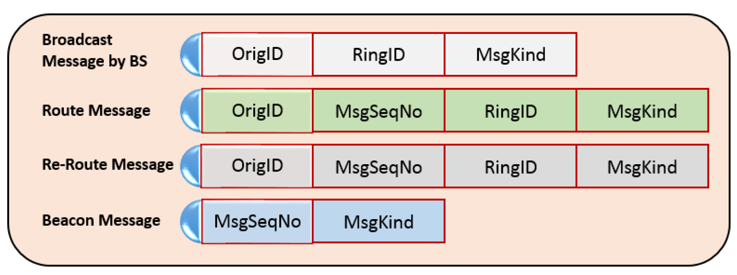
3.4. Message Formats Used in RARZ

To meet the needs of RARZ, we have defined some unique message formats, as shown in Figure 5. The header of each of the message is shown below.
When MsgKind is set to 0, the message is broadcast by the BS for ring formation. A value of 1 for MsgKind represents the send route message, i.e., the node’s own message, and 2 denotes a re-route message, i.e., a message that is received by an intermediate node for further relaying. MsgSeqNo field is used to keep track of the packet ID. Initially, it is set to 1. Once the message is received by nodes from the BS, they set their ringID to the MsgSeqNo. In case of a re-route message, the node that receives the packet first checks the packet ringID and compares it to its own ringID. When its ringID is less than the ringID of the received packet and the node is selected as the next hop, it updates the ringID field of the received packet by its own ringID, resets the MsgKind from 1 to 2, and sends it further. The same mechanism is applied at each hop. A beacon message with MsgKind ‘3’ is used to remove a scheduled packet that has already been sent by another node in the same ring. In this way, the packet is forwarded from upper-level rings to lower rings and routed to the BS. All the messages defined in the protocol and their fields are mentioned in Figure 5.

3.5. Protocol Description

The detailed description of the algorithms is depicted from the following algorithms,
Algorithm 1: Pseudo code for Network Configuration/setup phase
  • Begin
  • Initialization
  •  Set NodeRingID ← −1  //initially in simulation all nodes ID’s set to −1
  •  Set MaxRings ← 10
  •  Set MsgSeqNo ← 1
  •  Set RingID ← 0
  •  Set RecvPCKT ← 0
  •  Set NODE_RADIO_RANGE ← 100
  • While RingID < = MaxRings
  •  If Node = BS then, BroadCast Message with following parameters,
  •   Set MsgKind ← 0
  •   Set RingID ← RingID + 1
  •   Set NODE_RADIO_RANGE ← NODE_RADIO_RANGE + 50
  •  Else
  •   If NodeRingID ← −1 then
  •   Set NodeRingID ← RingID
  •   End If
  •  End If
  • End of While
  • Set NODE_RADIO_RANGE ← 100  //After ring formation, set the node max rangeEnd
  • End
Algorithm 2: Pseudo code for Data Communication phase
  • Begin
  • For each node Schedule MSG
  •  Set MsgKind ← 0
  •  If Msg = SelfMsg then   //SelfMsg is node own schedule message
  •   Set MsgKind ← 1
  •   BroadCast Msg
  •  End if
  •  If MsgKind ← 1 and Node ← BS then
  •   Set RecvPCKT ← RecvPCKT + 1
  •   Delete Msg
  •  Else
  •    If MsgScheduled = RcvMsgSeqNo then
  •   CANCEL Event
  •   Delete Msg
  •    Else
  •    If RcvPCKT_ ringID < = RingID then
  •    Delete Msg
  •    Else
  •    Schedule MSg for relaying by adding its own RingID
  •    End if
  •  End if
  • End while
  • End
Whenever a node acts as an intermediate node and sends the data further, there are certain nodes that would not see the data for which they have already started their timers. This will result in duplicate packets because their timers will also expire for the same data. We handled this situation in [31].

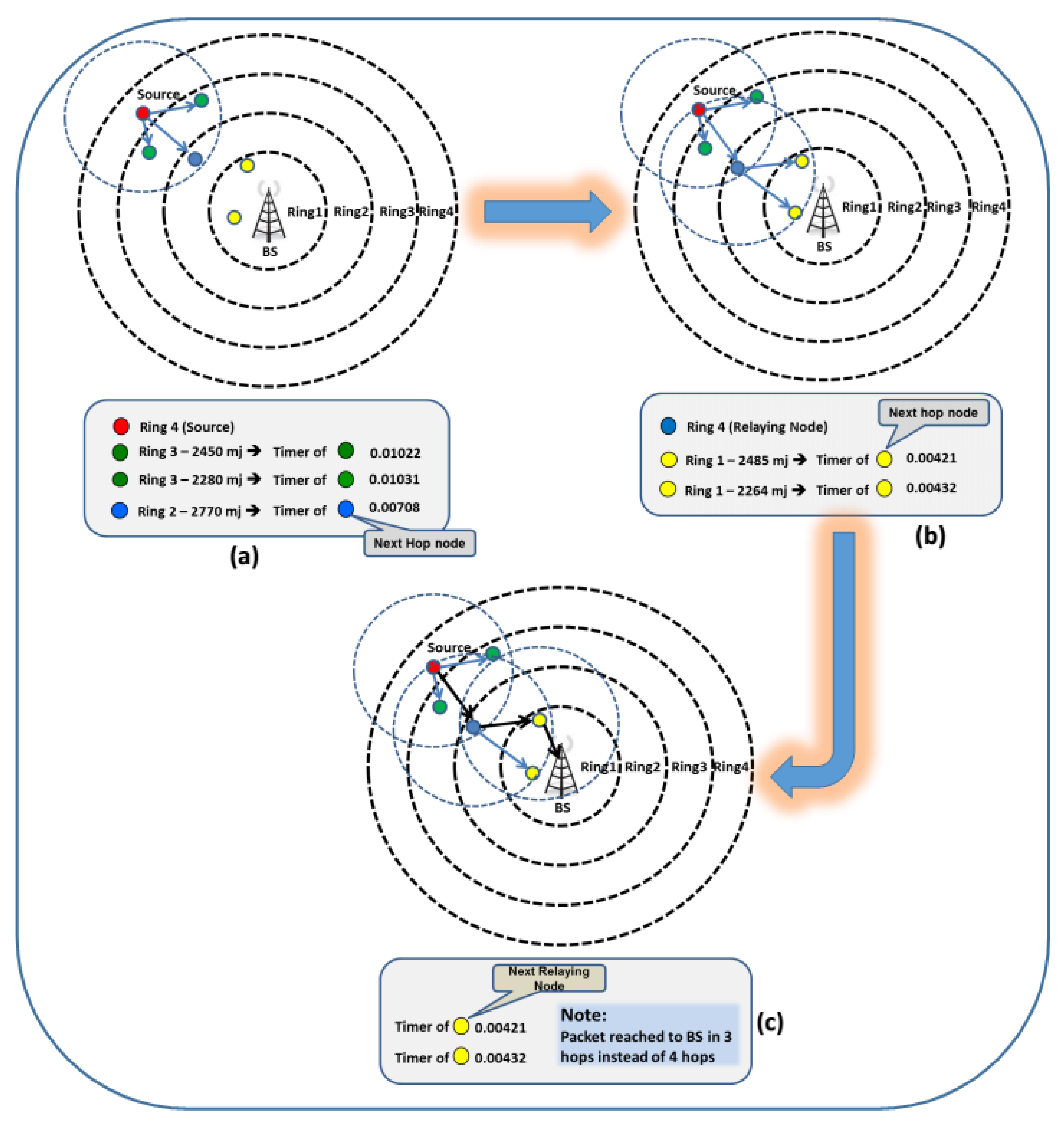
3.6. RARZ Algorithm (Example Scenario Taken from Simulation)

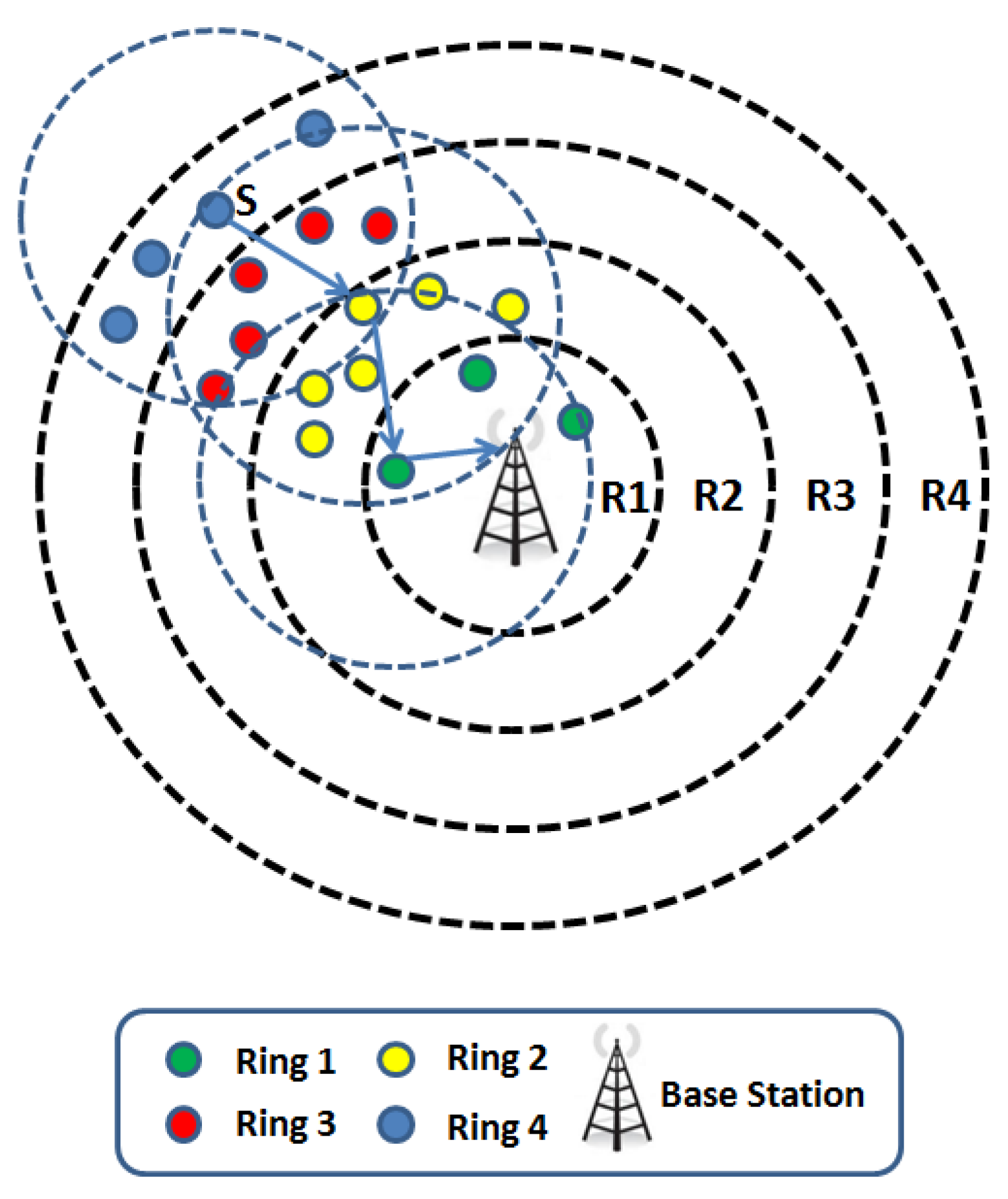
  • In Figure 6, Node S (Red Node) in ring 4 broadcasts the packet. Nodes in the lower rings 3 and 2 will receive the packet and start their timers as per Equation (1).
  • The timer of the node (blue) located in ring 2 expired first due to its energy level being the highest and its location (ringID 2) as compared to the nodes in ring 3.
  • Upon receiving the packet, which is sent by a node (blue) in ring 2, nodes (green) in ring 3 will cancel their timers. The nodes (yellow) in ring 1 will start their timers because they are located in the lower ring. The time of the node having a higher energy level will expire first and then it relays the received packet to BS. Hence the packet reaches BS in three hops instead of four.

4. Simulation and Results

4.1. Energy Model

The simulations have been carried out in an OMNET++-based simulation framework called INET. The energy consumption model is adapted from [5]. According to the energy consumption model in [5], transmitting a k bit message over a distance d, the following equations are followed:
E T x ( k , d ) = E T x e l e c ( k ) + E T x a m p ( k , d )
E T x ( k , d ) = E e l e c × k + E a m p × k × d 2 ,
and to receive a message,
E R x ( k ) = E R x e l e c ( k ) ,
  E R x ( k ) = E e l e c × k
where E T x ( k , d ) the energy required to transmit a k bit message over d meters and E R x ( k ) the energy required to receive a k bit message. E e l e c is the energy consumed for running the transceiver circuitry and is the energy consumed by the amplifier to achieve an acceptable SNR. The scenario is based on the MAC and physical layers of 802.11. Simulation setup and parameters are enlisted in Table 2.

4.2. Results and Discussion

Table 2 shows the parameters used in the simulations. For simulation, initially 100 nodes were randomly distributed in the network field with dimensions 600 m × 600 m. The performance of RARZ has been compared with AODV, Flooding, and AIMRP on the basis of the following parameters:
  • Average energy consumption (to check the average energy consumption in the system as time increments using the First Order Radio Model (FORM) model);
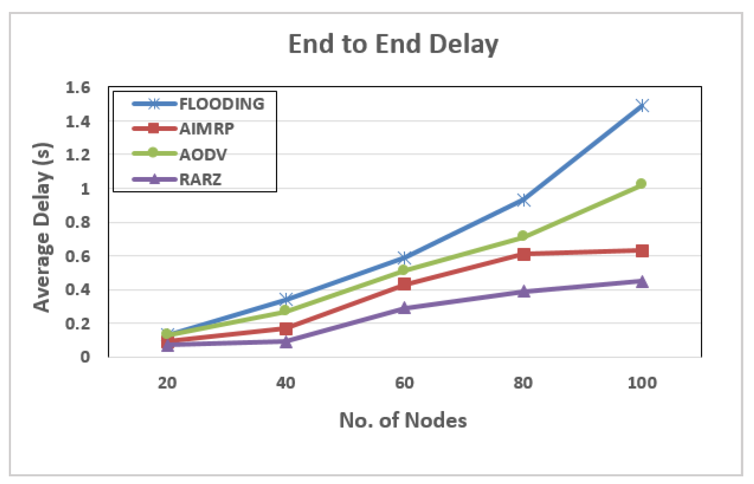
  • Average delay (latency) (average time required to transmit a packet from source to final destination (BS));
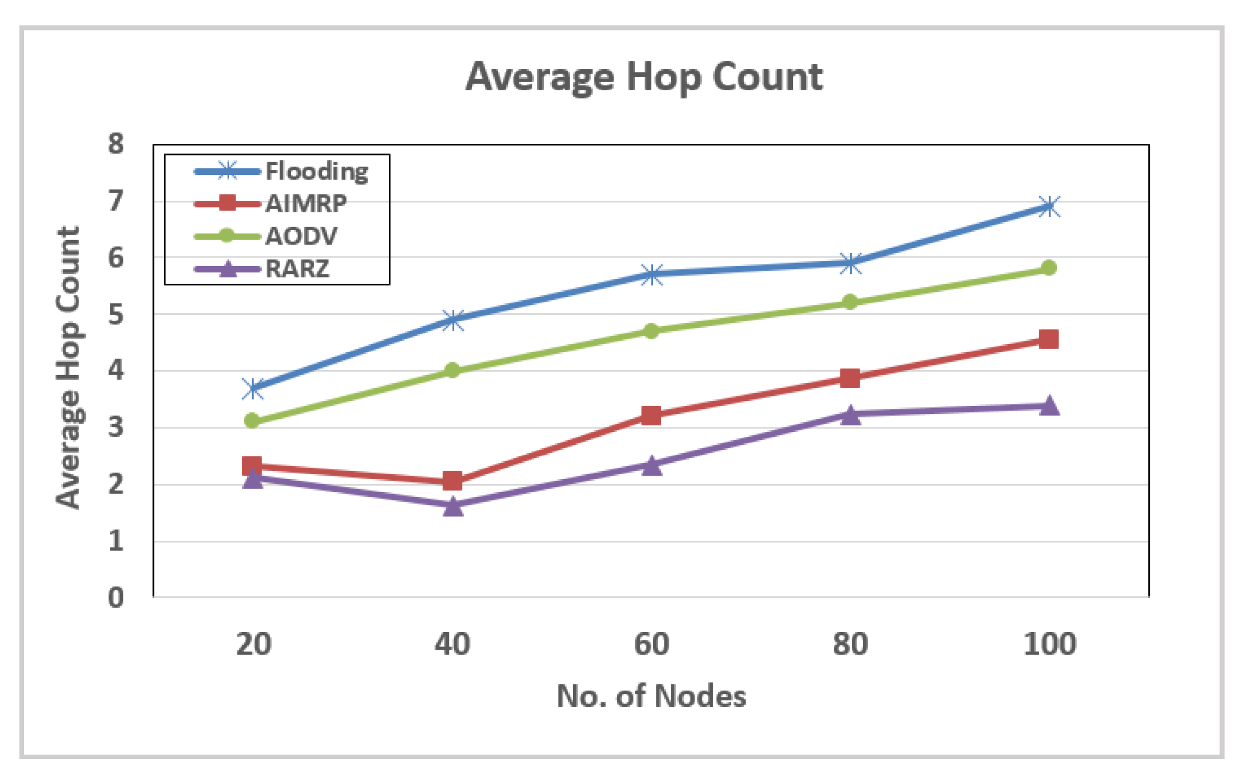
  • Average hop count (this parameter actually counts the total number of hops while sending packets using the RARZ scheme over time in the network w.r.t other protocols);
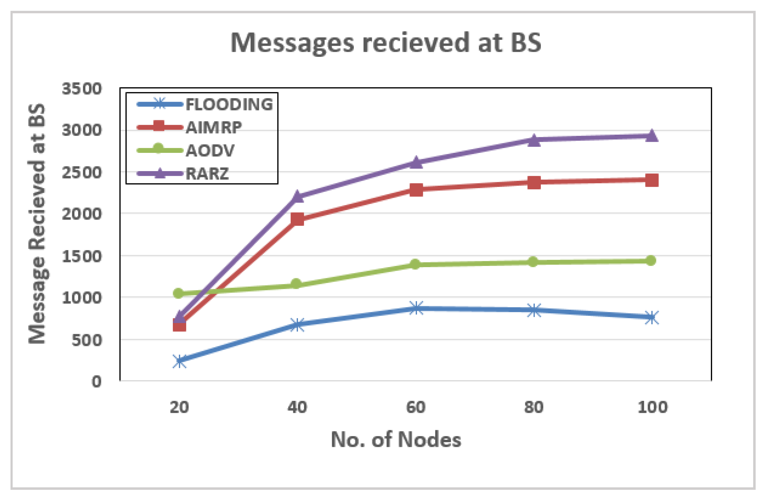
  • Delivery ratio (to define this parameter for evaluation requires that the total number of successfully transmitted and received packets in the network after any given time);
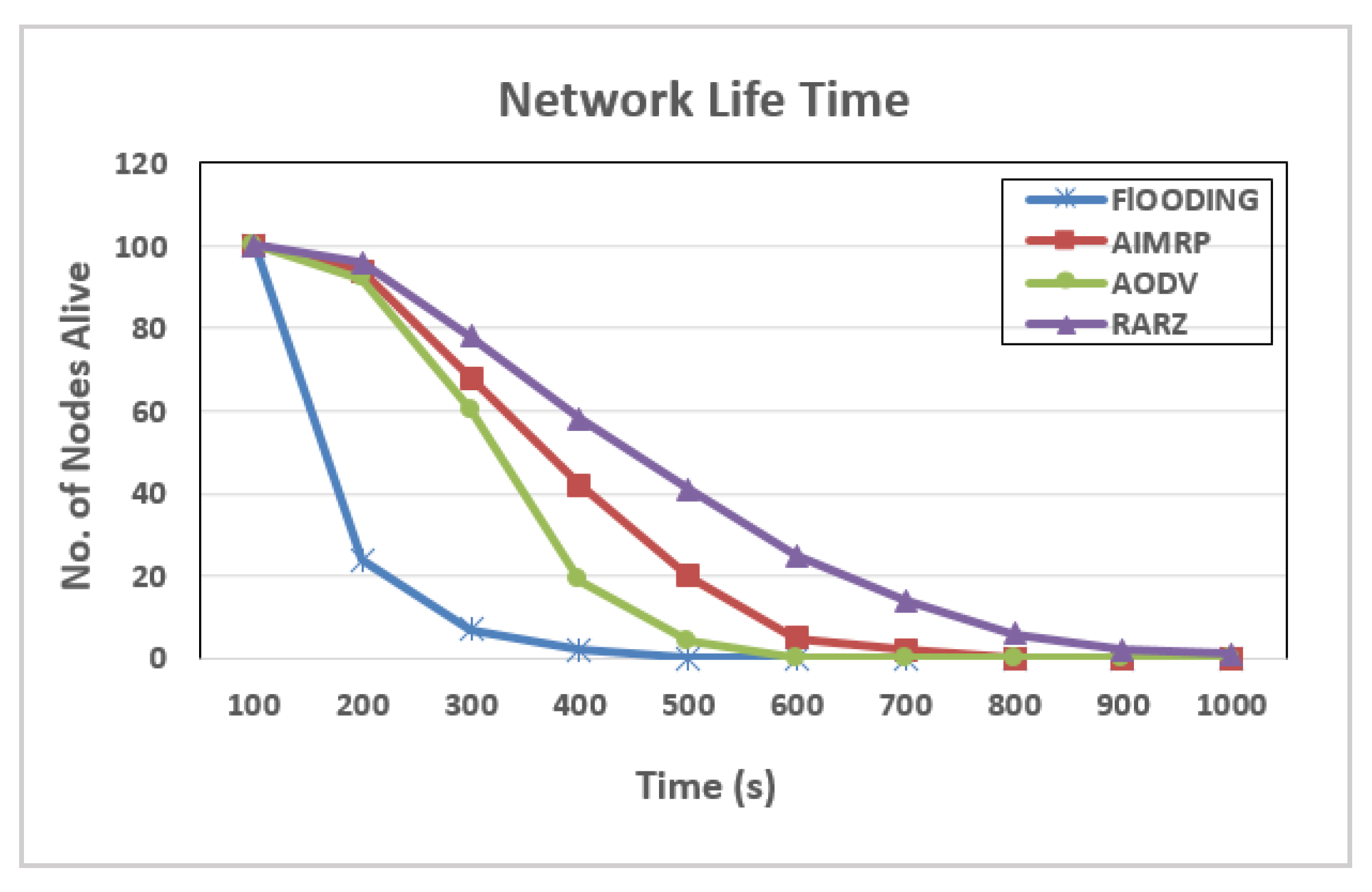
  • Number of nodes still alive over time (through this parameter we can easily check the number of alive and dead nodes over time, and observe the overall network lifetime as time increments).
Figure 7 shows the average energy consumption in the system as a function of time. According to the radio model used in the simulation, the energy of a node is depleted only upon the sending and reception of packets. It can be observed from the graph that with Flooding 3000 mJ of energy had been consumed in 600 s as opposed to the AODV, which consumes the same amount in 800 s. In other words, the per-second energy consumptions are about 5 mJ/s and 3.7 mJ/s for Flooding and AODV, respectively. With AIMRP the per-second average comes down to approximately 2.7 mJ/s, which is still higher than the 2.2 mJ/s observed for RARZ. Hence, RARZ performs better compared to AODV, Flooding, and AIMRP.
In Figure 8, we compared the protocols based on the number of nodes alive over a certain time period. RARZ again performs better than AODV, Flooding, and AIMRP because in RARZ the energy consumption is evenly distributed and only the nodes at the highest energy level are selected for routing.
The average latency of the four protocols is plotted against the number of nodes in the network in Figure 9. RARZ has the least delay amongst the protocols and, even with 100 nodes, the delay is around 0.4 s in contrast to AIMRP, AODV, and Flooding with delays of about 0.6, 1, and 1.5 s, respectively. RARZ outperforms the others because it is based on the minimization of the number of hops and consequently end-to-end delay.
Figure 10 shows the total number of data messages successfully delivered to the base station over a certain time period. RARZ outperforms AIMRP, Flooding, and AODV because it distributes the energy consumption evenly in the network.
In RARZ, the average hop count is lower than in AIMRP, as shown in Figure 11. This may be attributed to the fact that, in AIMRP, there is a maximum probability for a node within the immediate ring, of the sender, is selected without any energy considerations. However, RARZ selects nodes that are closer to the BS while considering the residual energy. This results in a lower average hop count compared to AIMRP, AODV, and Flooding.
To summarize, RARZ minimizes the average energy consumption in the network and also reduces the average hop count and end-to-end delay and increases the throughput.

5. Conclusions

We presented an energy-efficient protocol using the ring-zone model, RARZ, for a WSN. RARZ is a stateless protocol that is completely table-less and non-position-based. Energy-rich nodes in the network are used for data relaying purpose. This results in even distribution of energy consumption and avoids depletion of a node’s energy on a particular path. It also reduces the average hop count and end-to-end delay in the system and increases the throughput. In the future, we will assess the performance of RARZ on mobile sensors.
RARZ achieved 32% energy efficiency against AODV, 19% against AIMRP, and 39% against Flooding. Simulation results have shown that RARZ increases the network lifetime and minimizes end-to-end delay in the system. RARZ achieved a 51% lower end-to-end delay against AODV, 33% against AIMRP, and 59% against Flooding. RARZ performs better and is suitable for applications in which the data must reach the required destination in time. As it is proven from simulation results that the RARZ lifetime is higher as compared to other protocols, more messages are received at the BS. RARZ achieved 49–70% improvements in terms of the data messages successfully received at BS. Simulation results show that RARZ reduces the average hop count in the system by 17–23%.

Author Contributions

R.N.J. and W.Z. conceived and designed the experiments; R.N.J. performed the simulations; R.N.J. and W.Z. analyzed the results; R.N.J. wrote the paper, W.Z., W.J. and I.A.K. technically reviewed the paper.

Funding

This research was funded by National Natural Science Foundation of China (Grant No. 61461136002).

Acknowledgments

We are thankful to CAS-TWAS for supporting this work (CAS-TWAS No. 45, 2016). We thank the reviewers and the editor for numerous critical comments that largely improved our manuscript. We are also thanks to Dr. Kashif Bilal from COMSATS University Abbottabad Campus for his technical help during this research work.

Conflicts of Interest

The authors declare no conflict of interest.

References and Note

  1. Zahmati, A.S.; Abolhassani, B.; Shirazi, A.A.B.; Bakhtiari, A.S. An energy-efficient protocol with static clustering for wireless sensor networks. Int. J. Electron. Circuits Syst. 2007, 1, 135–138. [Google Scholar]
  2. Heinzelman, W.R.; Chandrakasan, A.; Balakrishnan, H. Energy-efficient communication protocol for wireless microsensor networks. In Proceedings of the 33rd Annual Hawaii International Conference on System Sciences, Maui, HI, USA, 4–7 January 2000. [Google Scholar]
  3. Heinzelman, W.R.; Sinha, A.; Wang, A.; Chandrakasan, A.P. Energy-scalable algorithms and protocols for wireless microsensor networks. In Proceedings of the 2000 IEEE International Conference on Acoustics, Speech, and Signal Processing (ICASSP’00), Istanbul, Turkey, 5–9 June 2000; pp. 3722–3725. [Google Scholar]
  4. Hall, D.L.; McMullen, S.A. Mathematical Techniques in Multisensor Data Fusion; Artech House: Norwood, MA, USA, 2004. [Google Scholar]
  5. Heinzelman, W.B.; Chandrakasan, A.P.; Balakrishnan, H. An application-specific protocol architecture for wireless microsensor networks. IEEE Trans. Wirel. Commun. 2002, 1, 660–670. [Google Scholar] [CrossRef] [Green Version]
  6. Stojmenovic, I. Position-based routing in ad hoc networks. IEEE Commun. Mag. 2002, 40, 128–134. [Google Scholar] [CrossRef] [Green Version]
  7. Kulkarni, S.; Iyer, A.; Rosenberg, C. An address-light, integrated MAC and routing protocol for wireless sensor networks. IEEE/ACM Trans. Netw. 2006, 14, 793–806. [Google Scholar] [CrossRef]
  8. Jiang, Q.; Manivannan, D. Routing protocols for sensor networks. In Proceedings of the First IEEE Consumer Communications and Networking Conference (CCNC 2004), Las Vegas, NV, USA, 5–8 January 2004; pp. 93–98. [Google Scholar]
  9. Baker, D.; Ephremides, A.; Flynn, J. The design and simulation of a mobile radio network with distributed control. IEEE J. Sel. Areas Commun. 1984, 2, 226–237. [Google Scholar] [CrossRef]
  10. Lindsey, S.; Raghavendra, C.S. PEGASIS: Power-efficient gathering in sensor information systems. In Proceedings of the Aerospace Conference Proceedings, Big Sky, MT, USA, 9–16 March 2002. [Google Scholar]
  11. Muruganathan, S.D.; Ma, D.C.; Bhasin, R.I.; Fapojuwo, A.O. A centralized energy-efficient routing protocol for wireless sensor networks. IEEE Commun. Mag. 2005, 43, S8–S13. [Google Scholar] [CrossRef]
  12. Shen, H. Finding the k most vital edges with respect to minimum spanning tree. Acta Inform. 1999, 36, 405–424. [Google Scholar] [CrossRef]
  13. Huang, B.; Hao, F.; Zhu, H.; Tanabe, Y.; Baba, T. Low-energy static clustering scheme for wireless sensor network. In Proceedings of the International Conference on Wireless Communications, Networking and Mobile Computing (WiCOM 2006), Wuhan, China, 22–24 September 2006; pp. 1–4. [Google Scholar]
  14. Madani, S.A.; Weber, D.; Mahlknecht, S. Position-based Routing Protocol for Low Power Wireless Sensor Networks. J. UCS 2010, 16, 1215–1233. [Google Scholar]
  15. Hussain, S.; Matin, A.W.; Islam, O. Genetic algorithm for energy efficient clusters in wireless sensor networks. In Proceedings of the Fourth International Conference on Information Technology (ITNG’07), Las Vegas, NV, USA, 2–4 April 2007; pp. 147–154. [Google Scholar]
  16. Yin, L.; Wang, C.; Øien, G.E. An energy-efficient routing protocol for event-driven dense wireless sensor networks. Int. J. Wirel. Inf. Netw. 2009, 16, 154. [Google Scholar] [CrossRef]
  17. Kim, S. Online energy efficient routing approach for QoS-sensitive wireless sensor networks. In Proceedings of the International Conference on Information Networking (ICOIN 2009), Chiang Mai, India, 21–24 January 2009. [Google Scholar]
  18. Le, H.-P.; John, M.; Pister, K. Energy-Aware Routing in Wireless Sensor Networks with Adaptive Energy-Slope Control (Lecture notes), Retrieved from University of California Berkley, EE290Q-2 Spring 2009.
  19. Nehra, N.K.; Kumar, M.; Patel, R. Neural Network based energy efficient clustering and routing in wireless sensor networks. In Proceedings of the First International Conference on Networks and Communications (NETCOM’09), Chennai, India, 27–29 December 2009; pp. 34–39. [Google Scholar]
  20. Cho, S.; Shrestha, B.; La, K.-H.; Hong, B.; Lee, J. An energy-efficient cluster-based routing in wireless sensor networks. In Communication and Networking; Springer: New York, NY, USA, 2011; pp. 15–22. [Google Scholar]
  21. Xu, W.J.; Sun, L.J.; Guo, J.; Wang, R.C. A Small World Routing Protocol in Wireless Sensor Networks. In Key Engineering Materials; Trans Tech Publications Ltd.: Stafa-Zurich, Switzerland, 2011; pp. 828–833. [Google Scholar]
  22. Pavithra, G.; Devaki, P. Link and location based routing mechanism for energy efficiency in wireless sensor networks. arXiv, 2014; arXiv:1403.1655. [Google Scholar]
  23. Chen, H.; Lv, Z.; Tang, R.; Tao, Y. Clustering energy-efficient transmission protocol for Wireless Sensor Networks based on ant colony path optimization. In Proceedings of the 2017 International Conference on Computer, Information and Telecommunication Systems (CITS), Dalian, China, 21–23 July 2017; pp. 15–19. [Google Scholar]
  24. Kannan, K.N.; Paramasivan, B. Development of energy-efficient routing protocol in wireless sensor networks using optimal gradient routing with on demand neighborhood information. Int. J. Distrib. Sens. Netw. 2014, 10. [Google Scholar] [CrossRef]
  25. Mahlknecht, S.; Madani, S.A.; Rötzer, M. Energy aware distance vector routing scheme for data centric low power wireless sensor networks. In Proceedings of the 2006 IEEE International Conference on Industrial Informatics, Singapore, 6–18 August 2006; pp. 1030–1035. [Google Scholar]
  26. Ben-Othman, J.; Yahya, B. Energy efficient and QoS based routing protocol for wireless sensor networks. J. Parallel Distrib. Comput. 2010, 70, 849–857. [Google Scholar] [CrossRef]
  27. Sabor, N.; Sasaki, S.; Abo-Zahhad, M.; Ahmed, S.M. A comprehensive survey on hierarchical-based routing protocols for mobile wireless sensor networks: Review, taxonomy, and future directions. Wirel. Commun. Mob. Comput. 2017, 2017, 2818542. [Google Scholar] [CrossRef]
  28. Sharma, S.; Puthal, D.; Jena, S.K.; Zomaya, A.Y.; Ranjan, R. Rendezvous based routing protocol for wireless sensor networks with mobile sink. J. Supercomput. 2017, 73, 1168–1188. [Google Scholar] [CrossRef]
  29. Madani, S.A.; Mahlknecht, S.; Glaser, J. CLAMP: Cross layer management plane for low power wireless sensor networks. In Proceedings of the 5th International Workshop on Frontiers of Information Technology, Islamabad, Pakistan, 17–18 December 2007; Citeseer: Forest Grove, OR, USA, 2007. [Google Scholar]
  30. Hajian, E.; Jamshidi, K.; Bohlooli, A. Improve energy efficiency routing in WSN by using automata. Int. J. Ad Hoc Sens. Ubiq. Comput. 2010, 1, 1–7. [Google Scholar] [CrossRef]
  31. Jadoon, R.N.; Shafi, J.; Hussain, S.A. Beacon based controlled routing in wireless sensor networks. In Proceedings of the 2012 International Conference on Computer Systems and Industrial Informatics (ICCSII), Sharjah, UAE, 18–20 December 2012; pp. 1–5. [Google Scholar]
Figure 1. Empirical analysis of hierarchical and flat multihop routing in WSN.
Applsci 08 01023 g001
Figure 2. The network configuration phase of RARZ.
Applsci 08 01023 g002
Figure 3. Routing scheme used in RARZ.
Applsci 08 01023 g003
Figure 4. Finding the next hop node in RARZ.
Applsci 08 01023 g004
Figure 5. Message formats used in RARZ.
Applsci 08 01023 g005
Figure 6. Routing illustration of RARZ.
Applsci 08 01023 g006
Figure 7. Average energy consumption over time.
Applsci 08 01023 g007
Figure 8. Number of nodes alive over time.
Applsci 08 01023 g008
Figure 9. End-to-end delay as a function of the number of nodes.
Applsci 08 01023 g009
Figure 10. Number of data messages successfully received at BS against the number of nodes.
Applsci 08 01023 g010
Figure 11. Average hop count vs. number of nodes.
Applsci 08 01023 g011
Table 1. Comparison of popular routing protocols in WSN.
Routing protocolsPrimary ObjectiveCentralize/DistributedSensor Nodes (Mobile/Static)Protocol CategorySink (Mobile/Static)Position Aware (Y/N)(Single/Multi-hops)Energy EfficientCross-Layer (Y/N)
LEACH-C [5]Extending network lifetimeCentralizedStaticHierarchicalStaticYesMultihopYesNo
LEACH [1,5,8]Extending network lifetimeDistributedStaticHierarchicalStaticYesMultihopYesNo
PEGASIS [10]Extending network lifetimeChain-basedStaticHierarchicalStaticNoMultihopYesNo
LESCS [13]Solving hotspot problemCentralizedStaticHierarchicalStaticYesMultihopYesNo
HCR [15]Efficient cluster formationCentralizedStaticHierarchicalStaticYesMultihopYesNo
AESC [18]Keep nodes alive for a given time periodDistributedStaticFlatStaticNoMultihopYesNo
TPR [14]Extending network lifetime, Greedy forwardingDistributedMobileFlat StaticYesMultihopYesYes
EADV [25]Extending network life timeDistributedStaticFlat StaticNo MultihopYesNo
CLAMP [29]Extending network lifetimeDistributedMobileFlatMobileYesMultihopYesYes
ELECP [20]Extending network lifetimeDistributedStaticFlatStaticNoMultihopYesNo
EEPSC [1]Extending network lifetimeCentralizedStaticHierarchicalStaticNoDirectYes No
AIMRP [7]Extending network lifetimeCentralizedStaticFlatStaticNoMultihopYesYes
Table 2. Simulation setup and parameters.
TypeParametersValues
NetworkField dimension600 × 600 m
Initial energy of each node3 J/battery
Location of each nodeRandom
Number of rings/zones10
ApplicationData packet size100 bytes
Broadcast packet size25 bytes
Packet header size25 bytes
Radio Model E e l e c 50 nJ/bit
E a m p 0.13 nJ/bit

