Review

Fabrication and Use of Organic Electrochemical Transistors for Sensing of Metabolites in Aqueous Media

1
Université Paris Diderot, Sorbonne Paris Cité, ITODYS, UMR 7086 CNRS, 15 rue J-A de Baïf, 75205 Paris CEDEX 13, France
2
ValoTec, 1 Mail du Professeur Georges Mathé, 94800 Villejuif, France
*
Author to whom correspondence should be addressed.
Appl. Sci. 2018, 8(6), 928; https://doi.org/10.3390/app8060928
Submission received: 9 May 2018 / Revised: 1 June 2018 / Accepted: 1 June 2018 / Published: 4 June 2018
(This article belongs to the Special Issue Novel Applications of Organic Bioelectronics)

Abstract

:

Featured Application

Sensing organic molecules in water.

Abstract

This review first recalls the basic functioning principles of organic electrochemical transistors (OECTs) then focuses on the transduction mechanisms applicable to OECTs. Materials constituting the active semiconducting part are reviewed, from the historical conducting polymers (polyaniline, polypyrrole) to the actual gold standard, poly-3,4-ethylenedioxythiophene: polystyrene sulfonic acid (PEDOT:PSS), as well as the methods used to fabricate these transistors. The review then focuses on applications of OECTs for the detection of small molecules and more particularly of metabolites, with a distinction between enzymatic and non-enzymatic transduction pathways. Finally, the few patents registered on the topic of OECT-based biosensors are reviewed, and new tracks of improvement are proposed.

1. Introduction

Organic electrochemical transistors (OECTs) have been widely reported in the literature [1,2], even very recently [3]. From the very first example of OECT (described in 1984) to the devices produced today, progress has been considerable. In 1984, experiments were carried out using chips consisting of three Au electrodes deposited on the SiO2 layer of a Si wafer. Electrodes were 3 µm wide × 140 µm long, with a distance between electrodes of 1.4 µm. The organic semiconducting layer was a 0.12 µm thick polypyrrole layer made by in situ electropolymerization of the monomer. The on/off switch time was ca. 10 s (operating frequency of about 0.1 Hz), the on/off ratio was around 3000 and the maximum transconductance of about 0.1 mS at VGS = 0.1 V. For a contemporary OECT of similar dimensions, typically fabricated by means of printing technologies using poly(3,4-ethylene-dioxythiophene:polystyrene sulfonate (PEDOT:PSS) and having similar thickness, the transconductance is about 150 times higher and the maximum operating frequency reaches 103 Hz, i.e., 4 orders of magnitude higher. It is remarkable to note that, in the 1984 article, the authors wrote that “[their device] has no immediate practical application”. However, they also wrote that “There is presently considerable interest in interfacing microelectronic devices with chemical and biological systems for sensor applications […]”. It was a premonition. Indeed, OECTs have been applied to biosensing quite early, associated with enzymes [4,5,6]. This is because, due to their functioning mechanism (already identified at the time), they brought into play the same charge carriers as most biological functions, i.e., electrons but also ions, and were therefore sensitive both to electron transfer to/from redox enzymes or ions (e.g., protons) produced from other types of enzymes.
This is a characteristic which distinguished them from organic field-effect transistors (OFETs), which started to raise the attention of researchers exactly at the same period (precisely, 1983 for the first polyacetylene-based OFET [7]), and a few years later for applications to gas sensing (halogens, ammonia, oxygen [8,9,10] or even vapors of H2O, NO or H2O2 [11,12,13,14]). However, OFETs never really produced any applicable results in the framework of biosensors in aqueous environment because of high operating voltages, of several tens of volts, which impede any measurements because of water electrolysis. Ion-sensitive organic field-effect transistors (ISOFETs), based on the same working principles of their inorganic counterparts (ISFETs) developed earlier [15,16], solved this problem of high operating potential, the electrolyte being not in direct contact with the semiconductor. However, these devices were confined mostly to protons detection [17,18,19] or, in any case, to charged species.
As we show in this review, OECTs use both potentiometry and amperometry in their working principles. In that sense, OECTs are devices that represent a bridge between ISOFETs and classical amperometry, which certainly explains their success. This area of research is very active and several reviews have already been published on OECTs in general, for example by Kergoat et al. [1] or Rivnay et al. [3], or on OECTs applied to biology, for example by Liao and Yan [20], Liao et al. [21], Strakosas et al. [22] or Tixier-Mita et al. [23]. This present review, after going back to the basic functioning principles, along with details on transductions applicable to OECTs, reviews materials, fabrication techniques and then sensing applications. We focus on the detection of small molecules and more particularly of metabolites, with a distinction between enzymatic and non-enzymatic devices. Finally, the few patents registered which deal with OECT-based biosensors are reviewed. From the discussed key points, the conclusion identifies new tracks of improvement.

2. Functioning Principles and General Concepts for Transduction

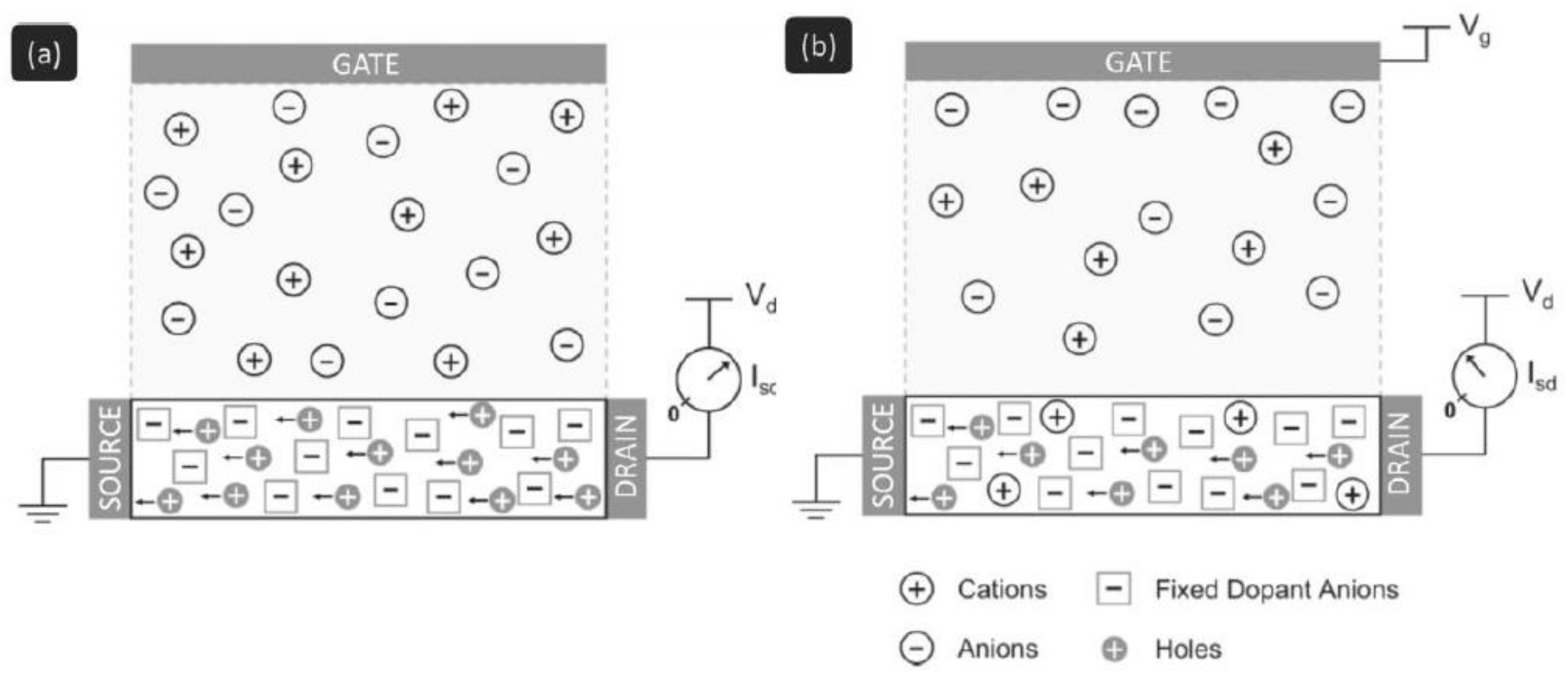
2.1. Functioning Principles

The OECT is a three-terminal device (source, drain and gate) in which source and drain electrodes are connected by an organic channel made up of a conductive polymer and an electrolyte which separates this polymer from a third contact, the gate electrode. The development of OECTs was initiated in 1984 by White et al. who elaborated an electrochemical transistor based on an electropolymerized polypyrrole film [24]. This early OECT worked inside an aqueous electrolyte solution. Its working principle was based on changes in the polypyrrole conductivity induced by the application of a gate voltage able to switch the polymer between its oxidized and reduced states. Since this pioneering work, several organic conducting polymers (OSCs) have been investigated, such as polyaniline [25], polycarbazole [26] or polythiophene [27]. However, the most commonly employed material for OECTs is poly(3,4-ethylenedioxythiophene) doped with poly(styrene sulfonate) (so-called PEDOT:PSS) [28,29], a positively-doped (p-doped) OSC.
The working principle of PEDOT:PSS OECTs (i.e., the modulation of the source-drain current) relies on the electrochemical doping/dedoping effect of the OSC channel that occurs when an appropriate gate voltage is applied. In such devices, the source electrode is grounded, so that voltages applied to the drain and gate electrodes are against the source. At zero bias voltage on the gate electrode, the transistor is in its “on” state; high current flows through the channel between source and drain under external polarization of the drain contact. When the gate electrode is put at a positive potential (against the source), the channel is consequently reduced. Cations in the electrolyte solution enter into the PEDOT:PSS and compensate the negatively charged sulfonate ions on the PSS, thus dedoping the OSC; this is the so-called depletion mode of operation, illustrated in Figure 1. Ionic interactions reduce the density of positive charge carriers (hole polarons), which leads to the decrease of the OSC conductivity (i.e., smaller currents cross the channel). In that sense, OECTs can convert ionic currents into electric currents.
Bernards and Malliaras proposed a model that reproduces the transient response (the rate at which the transistor responds to external changes such as a potential change at the gate) and the steady-state by considering OECTs as a combination of an ionic and an electronic circuit [30]. The electronic circuit models the flow of holes inside the channel and its variations during the dedoping process, while the ionic circuit has been modeled as a capacitor and a series resistor. In the model, the resistance represents the ionic strength of the electrolyte and the capacitor the number of ions that can be stored in the channel bulk. The operating principle of the OECT then relies on the interplay between the ionic and electronic currents. One should thus consider the parameters that influence transport properties (i.e., nature of the gate material, resistance of the electrolyte, and the geometry of the gate and channel) and tune them according to the targeted application.
The most important feature of OECTs is their amplification property. A recent review by Gualandi et al. [31] describes very well the relation between the amperometric gate current, apparent gate voltage and drain current. The figure of merit corresponding to amplification is called the gain. High gain is indeed crucial for transistors in the field of biosensing as it can provide high sensitivity, low limit of detection (LOD) and good signal-to-noise ratio. The efficiency of the amplification is measured by the transconductance gm, which is defined as the slope of the transfer characteristic of the transistor: gm = ΔId/ ΔVg, where ID represents the drain current and VGS, the gate voltage. Therefore, a better gain is related to higher values of gm. Transconductance values in the mS range have been reported for OECTs fabricated with solution-processed materials [32]. Moreover, through the optimization of the transistors’ geometry, peak transconductance values at zero gate voltage have been obtained [33] allowing the device to be operated efficiently even at very low voltages. This capability is remarkably adapted for biosensing applications which involve fragile samples maintained under bias for long periods of time [34]. In addition, it guarantees low power consumption. Besides, the switching speed of OECTs is now lower than 1 ms, which is far above expectations for biosensing applications.
However, OECT transconductance exhibits a non-monotonic dependence on gate voltage (bell-shaped curve). This behavior appears to be a general trend for OECTs as it has been reported many times independently from the device’s geometry, materials used (electrodes, conductive polymers) or elaboration technology [35]. To account for this behavior, two distinct origins have been proposed in the recent literature. The first one points out the role of contact resistance in OECTs operating in the depletion mode. For example, the model developed by Kaphle et al. shows that the dependence of contact resistance with gate voltage can lead to a bell-shaped transconductance [36]. The second one suggests that disorder in the OSC causes non-linearities in the transfer curves of OECTs. Based on a hopping transport model applied to disordered organic materials, Friedlein et al. showed that non-monotonic transconductance occurs even in the absence of contact resistance [35]. While the former explanation implies that this behavior is the result of poor electrical contact to the channel, the latter makes it an intrinsic property of OECTs, suggesting that for the development of new materials and devices, one should both optimize thin films’ interfaces and provide high transconductances over a broad operating voltage range.

2.2. Transduction Principles

Biosensors are detection devices comprising recognition entities of biological origin coupled with a transducer for translating the formation of a biological complex into an electrical signal. By extension, a biosensor can also be made of recognition entities that could be fully synthetic, but for the recognition of biomolecules. Biosensors are then composed of two parts: a (bio)chemical recognition element (the probe) and a transducing element (the transducer). This review focuses on small target molecules; therefore, we do not deal with applications targeting deoxyribonucleic acid (DNA), antibodies, cells or other microorganisms. However, probes having affinity for small target molecules are extremely diverse and can be DNA (as aptamers), antibodies, enzymes or even synthetic ligands or molecularly imprinted polymers.
The concept of electrochemical transduction historically started at the beginning of the 19th century and largely developed in the 1970s with the possibility of using ion receptors (e.g., crown ethers, peptides or other chelators) immobilized on an electrode, which can increase the charge concentration or the distribution of charges over an electrode, then be sensed potentiometrically by a change in (electro)chemical potential at the electrode vicinity. However, potentiometry can be considered as a passive transduction in the sense that no external signal is supplied to the system. Consequently, and as predicted by the logarithmic form of the Nernst equation, a relatively large change in concentration results in a limited change in potential, which limits the overall sensitivity of the method. Readers who want to go deeper into theory can read the book of Morf [37] or the review of Bobacka et al. [38].
Converse to passive transductions, active transductions rely on the fact that the transducer supplies energy to the system, for example by applying an external electrochemical potential able to inject or withdraw electrons from the system, as all amperometric sensors do (the first amperometric sensor was reported in 1956 by Clark [39]). Consequently, amperometry has a higher sensitivity compared to potentiometry. The very first active device which combined potentiometry with an amplification strategy was the ion-selective field-effect transistor (ISFET) from Bergveld [15].
Today, transduction schemes used in OECT-based chemical sensors rely on polarization of the interface where the probe molecule is immobilized, or on electron transfer reactions occurring on these interfaces. The choice of one transduction or the other largely depends on the process which is involved upon recognition of the target by the immobilized probe: does it lead to accumulation of charges at the interface, or does it produce charge transfer (a current)?

2.2.1. Polarization of the Gate/Electrolyte or OSC/Electrolyte Interfaces

Due to the functioning principles of OECTs, ions are part of the device itself: in the electrolyte where they participate to interfacial capacitances, and as doping ions within the OSC [22]. In the electrolyte, it has been shown that any change in concentration (ionic strength) affects the drain current [40,41], as well as changes in the nature of the ions present into the electrolyte [34,42], which leads to a shift of the effective gate voltage due to a change in the gate/electrolyte interfacial capacitance. An increase in the ion concentration at this interface leads to a decrease in the associated potential drop, which in turns participates to an increase of the effective gate voltage, and therefore an easier channel dedoping [30]; the symmetric phenomenon occurs if the ion concentration decreases, which leads to a decrease of the effective gate voltage and a more difficult channel dedoping. In a similar way to what occurs in ISFETs, such local potential changes due to the polarization of an interface by specific accumulation of ions could be performed using an ion-selective membrane that allows only specific cations to be accumulated, such as artificial polymer membranes [43], biological membranes [44], biomolecules such antibodies [45], DNA [46] or living cells [47], or even nanoparticles (the surface of which being charged depending on pH, for example). pH-sensitive membranes can also be used, for pH sensing or for transducing the activity of enzymes which locally modify the pH by production of H+ [48].

2.2.2. Increased Ion Flow at the OSC/Electrolyte Interface

It has been also shown that, if a selective membrane is placed on the OSC, not only does the capacitance change but it results in an increased concentration of specific cations going through the membrane itself and penetrating the OSC, dedoping it and consequently decreasing the drain current [44,49].

2.2.3. Electron Transfer to the Channel or to the Gate

Electron transfer is certainly the main investigated transduction pathway on OECTs. For this purpose, due to their superior selectivity compared to any synthetic probe or synthetic catalyst, redox enzymes are often used for selective oxidoreduction of the analyte [50,51]. Three classical pathways could be followed: direct electroreduction of one of the enzyme products on the gate (type I), indirect (mediated) electron transfer between the gate electrode and the redox center of the enzyme (type II) or, when possible, direct electrical connection between the gate and the redox active center of the enzyme (type III). There are multiple examples of type I enzymatic OECTs, the most common being re-oxidation of H2O2, a co-product of some oxidase enzymes such as glucose oxidase, on platinum gates [52]. This oxidation corresponds to the transfer of electrons from the molecule to the gate which in turn causes a shift of the effective gate voltage by decreasing the polarization of the gate/electrolyte interface, thus causing a decrease of the source–drain current. Other catalytic materials may be used instead of bulk platinum, for example Pt nanoparticles [53] or graphene [54]. Most of these materials, in addition to catalytic properties, present high surface-to-volume ratio compared to bare Pt, which helps decrease the limits of detection. Type II enzymatic OECTs were also described, for example using ferrocene as a mediator for the transfer of electrons from the active enzymatic site to the gate [55]. Type III enzymatic OECTs have been much less investigated, probably because direct electron transfer from enzymes is only possible for a small number of enzymes; however, it is a well-described configuration in the field of amperometric sensors [56], which could be applied in the field of OECTs.
It should be pointed out that there are also some examples of enzyme-free OECTs where the electroactive target molecules, such as ascorbic acid [57] (Figure 2) or dopamine [58], are directly electrooxidized on the gate electrode. However, this is often at the price of weak selectivity compared to the extreme selectivity of most enzymes.

2.3. OECTs for Wearable Electronics Applications

To complete this section describing the context of OECTs and OECTs-based sensors working principles, a few comments on the applications of such type of transistors in the field of wearable electronics are necessary.
Wearable electronics is the branch of electronics dealing with electronics devices that can be worn on the body, either as accessories attached to a textile substrate or directly incorporated inside the fabric (fiber-based devices). Wearable electronic devices have been gaining considerable attention especially in the field of healthcare monitoring as, being in direct contact with the skin, they can provide important information on the physical and chemical signals emitted by the human body [59].
Within this context, OECTs-based sensors seem particularly suitable for the fabrication of wearable devices, essentially for three main reasons [60]. First, as described in earlier sections, OECTs are biased using very low voltages (<1 V), allowing the utilization of portable, low-power sources. Secondly, when transistors are used as sensors the transduction and amplification phenomena are coupled in a single device, which thus reduces the number of electronic components needed for signal acquisition and treatment. Lastly, but probably most importantly, OECTs do not require a three-electrode setup (more specifically, they do not require a reference and counter electrodes, universally needed for other types of electrochemical sensors) which greatly simplifies the readout electronic circuit.
Details on the fabrication and sensing performances of OECTs and OECTs-based sensors on fibrous substrates are given in Section 3.3.4 and Section 3.3.5.

3. Materials and Fabrication Techniques

3.1. Conducting Polymers

In the framework of OECTs, the optimization of the organic channel connecting the drain and the source is of paramount importance. This channel is made of an OSC, whose conductivity can be modulated in response to an external stimulus (typically, an electrochemical reaction occurring at the gate or directly at the channel, as described above). In their neutral state, OSCs typically exhibit low electrical conductivity. Upon chemical or electrochemical oxidation (p-doped OSC) or reduction (n-doped OSC, less frequent), mobile charge carriers are formed in the backbone of the OSC and counterions penetrate the polymer film to ensure electroneutrality. The OSC thus acquires its conducting properties. This process is ideally reversible, and the conductivity of an OSC can be modulated through a careful control of its oxidation state. We will see below that some OSCs are self-doped and are dedoped by application of a positive gate voltage (case illustrated in Figure 1, called “normally on”), whereas some other OSCs, less used nowadays, are intrinsically dedoped and are doped by application of a negative gate voltage (called “normally off”).
The development of an efficient OECT for biosensing applications, beyond the choice of the probe/target system, is intimately tied with the material used in the fabrication of the channel. Ideally, the choice of this material should follow several general guidelines. From a practical point of view, the OSC of choice should be easy to process, and exhibit low fabrication costs. For an implantable or wearable device, mechanical flexibility should also be considered. From a physical and chemical point of view, the polymer should exhibit high electrical conductivity. It should also be stable over time, and towards chemical or electrochemical modifications. Below are discussed the various organic conducting polymers which have been employed in OECTs since the emergence of this device. Their structures are given in Figure 3.

3.1.1. Polypyrrole

Early examples of OECTs relied on the use of polypyrrole (PPy) (Figure 3a), a conjugated polymer exhibiting relatively low conductivity in its reduced state. Upon oxidation (p-doping), the conductivity of polypyrrole sharply increases and can reach values as high as 102 S∙cm−1 [61]. Polypyrrole is typically obtained through the oxidative polymerization of pyrrole. This polymerization process can be carried out by chemical (oxidation by iron(III) chloride, typically) or electrochemical (cyclic voltammetry or chronocoulometry) methods. The optimization of a variety of parameters, such as the choice of solvent, the pyrrole-to-oxidant ratio (chemical methods), the applied voltage (electrochemical methods), or the nature of the counter-anion (dopant), led to the production of highly conductive polymers.
The conducting properties of PPy were used by White et al. in 1984, to produce microelectrode arrays working as transistor-like devices [24]. In this early and very popular work, more than three electrodes were used in total: the authors describe the functionalization of a three-electrode (source, drain and gate) “array” with a thin film of polypyrrole, but also used a reference electrode and an auxiliary (counter) electrode. Upon application of a sufficiently positive gate voltage, corresponding to the oxidation potential of polypyrrole, the PPy film connecting the three electrodes becomes conducting and allows for a current to flow between the source and the drain, essentially turning the transistor-like device “ON”.
Interestingly, the conductivity of PPy is also sensitive to pH changes. Nishizawa et al. [62] noted that the conductivity of PPy varies by 2 orders of magnitude between pH 3 and pH 11, and subsequently used this property to create a penicillin biosensor based on a PPy-modified transistor-like device. In the framework of electrochemical transistors, a polypyrrole channel connecting the source and the drain can therefore be turned “ON” or “OFF” through the application of an adequate gate voltage, or through a modification of the pH in the electrolytic solution.
One major drawback of PPy is its inherently poor electrochemical and chemical stability. When the polymer is overoxidized, either through the application of a moderately high positive potential (>+0.5 V vs. SCE) or upon exposure to oxygen or water, its resistance increases dramatically [63]. This low stability of polypyrrole therefore led to the investigation of other OSC candidates, such as polyaniline and polythiophene derivatives, for the development of OECT-based sensors.

3.1.2. Polyaniline

Polyaniline (PANI) (Figure 3d), a conducting polymer obtained through the oxidative polymerization of aniline, has been extensively studied in the framework of OECTs. As for polypyrrole, the electronic conductivity of PANI can be modulated through the modification of its oxidation state: the low conductivity of the reduced state (leucoemeraldine state, Figure 2d with n = 1 and m = 0) sharply increases upon oxidation (emeraldine state, n = m = 0.5), up to a certain point (pernigraniline state, n = 0, m = 1)) after which the conductivity decreases. As in the case of PPy, the conducting properties of PANI can also be modulated through pH changes, reinforcing its attractiveness as a candidate for OECT-based biosensors. As with PPy, PANI can be readily synthesized through chemical or electrochemical oxidation of its monomer, aniline.
As an early example, similar to the one published with PPy, Paul et al. functionalized an array of Au-microelectrodes with thin films of PANI, and were able to turn their transistor-like device “ON” or “OFF” through modifications of the pH of the solution, or through the addition of redox reagents (Fe(CN)63−/4− or Ru(NH3)63+/2+) in the solution [25]. The authors noted that PANI films deteriorated rapidly and irreversibly lost their conducting properties when held at potentials higher than 0.7 V vs. SCE, or when operated in neutral or alkaline solutions (pH > 6). This lack of stability upon moderate oxidation of mild pH is detrimental when one seeks to design an efficient OECT-based biosensor; for this reason, more stable materials were developed.

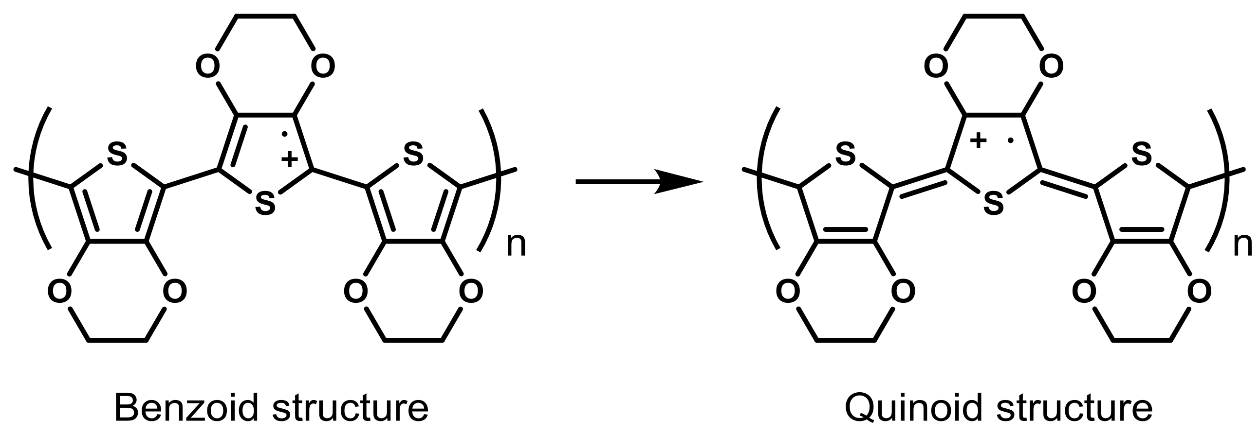
3.1.3. Polythiophene Derivatives

In an effort to find a stable OSC for OECT devices, research recently focused on a third family of conducting polymers, based on sulfur-containing heterocycles. Polythiophene (PT, Figure 3b) and its derivatives, more particularly poly(3,4-ethylenedioxythiophene) (PEDOT) (Figure 3c), have been at the center of the investigations on OECT-based biosensors for the last 15 years. PT derivatives share a good stability towards chemical and electrochemical modification, as well as towards air oxidation [64,65,66]. Some of these derivatives were first used in for the fabrication of OECTs by Thackeray et al. in 1985 [27], again using the same architecture as for their previous works on PPy and PANI, who functionalized Au microelectrodes arrays with poly(3-methylthiophene) and were able to amplify chemical signals such as the reduction of IrCl62− to IrCl63− at the gate.
To further improve the characteristics of polythiophene derivatives, new sulfur-containing conducting polymers were designed [64]. One of these derivatives, PEDOT, proved itself of interest in the framework of OECTs. PEDOT is a conducting polymer obtained through the oxidative polymerization of 3,4-ethylenedioxythiophene (EDOT). It exhibits high conductivity (300 S cm−1) and high stability in its oxidized state. In addition, PEDOT can be coupled with another polymer, poly(styrene sulfonate) (PSS), to improve its solubility in water (in fact, PEDOT:PSS blend forms a stable colloidal suspension) and also improve its conductivity, by stabilization of the positively charged bipolaron of PEDOT by negatively charged PSS anions (Figure 4).
Owing to its outstanding characteristics, PEDOT:PSS quickly became one of the most used and studied OSC in the field of OECTs and OECT-based biosensors, and almost completely replaced the aforementioned, less stable OSCs as the choice material for the fabrication of OECTs. This in turn led to a shift in OECT research, from the quest for the most adequate material to the development of improved strategies for the enhancement of the properties of PEDOT:PSS-based OECTs and their fabrication.
Below are discussed some of the strategies employed to enhance the electrical conductivity of PEDOT:PSS, and improve its adhesion to different substrates.
As the standard conductivity of PEDOT:PSS is intrinsically related to the commercial source of PEDOT:PSS, a table recapitulating all sources of PEDO:PSS used is available at the end of this section.

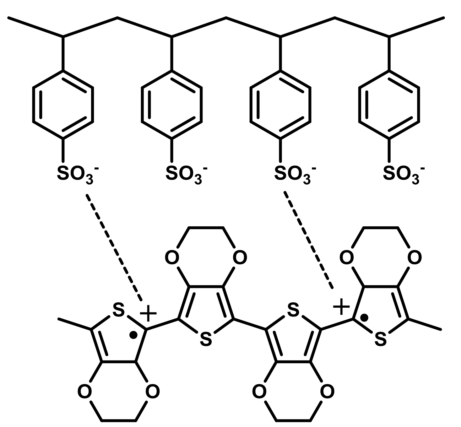
3.2. Strategies for Enhancement of PEDOT:PSS Properties

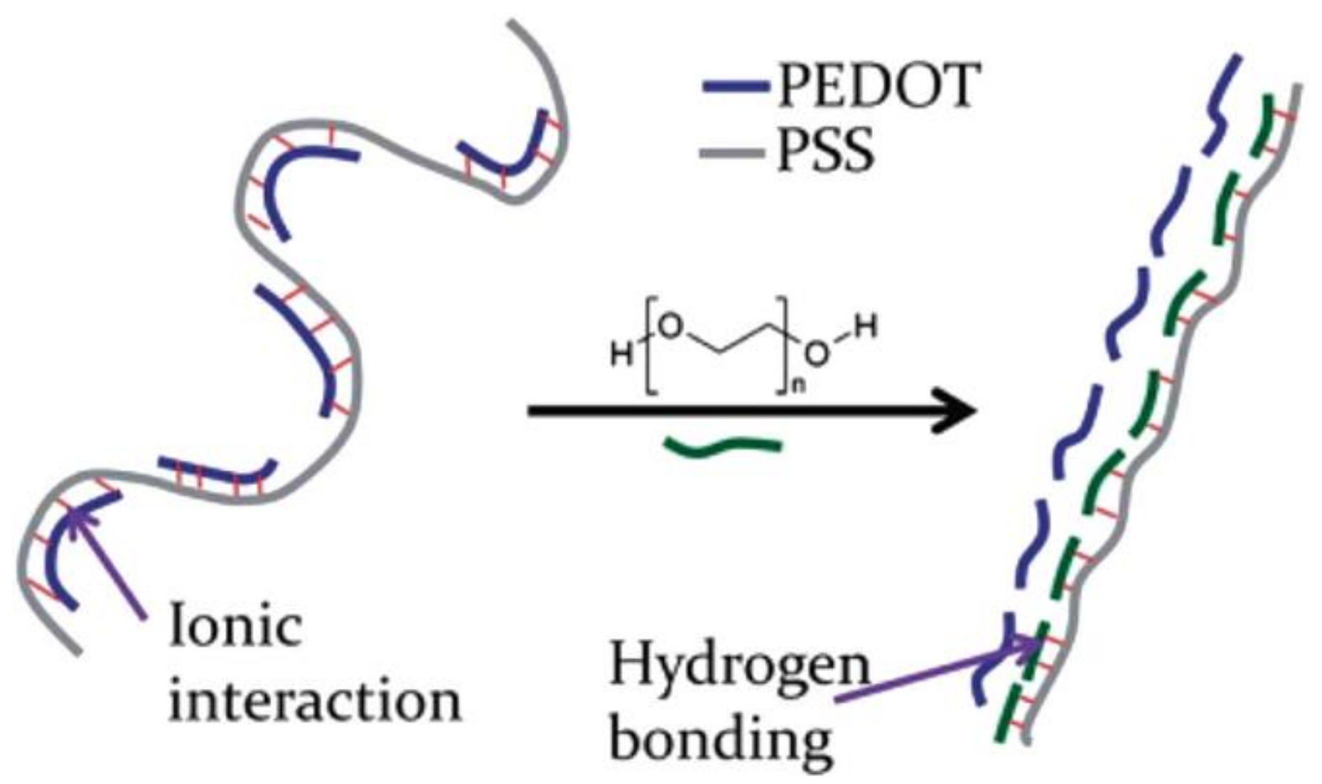
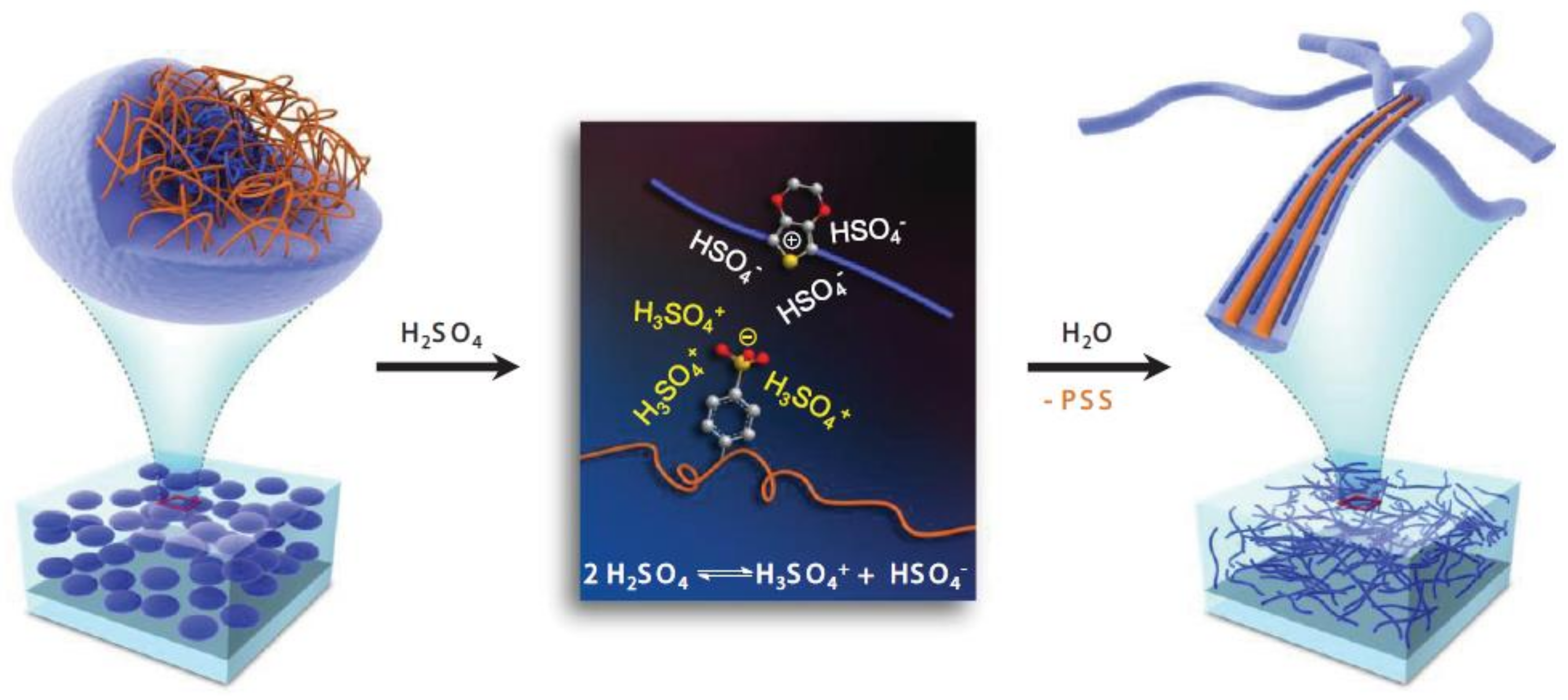
3.2.1. Enhancement of Electrical Conductivity and Adhesion of PEDOT:PSS

A good organic conducting polymer is characterized by its ability to keep a stable charge injection capacity as well as good charge mobility with time. The conductivity enhancement can be related to the presence of different counter-ions or to the intrinsic structure of the polymer. PEDOT:PSS is by far the most used organic conducting polymer involved in OECTs. Many studies were performed to increase the stability, the wettability and the electrical properties of PEDOT:PSS polymer. Few years ago, Shi et al. [67] reviewed the different techniques that were reported in literature to improve the electrical conductivity of the PEDOT:PSS films. A brief summary is presented here.
The easiest way to enhance the conductivity of PEDOT:PSS films is a thermal treatment performed after deposition. Huang et al. [68] studied the influence of the temperature (range of temperature from 100 to 250 °C) as well as the time of curing in an inert atmosphere as well as in air. They concluded that the thermal treatment is an effective method to improve the conductivity of PEDOT:PSS of at least one order of magnitude (10−3 to 10−2 S cm−1). The influence of UV or UV-ozone post-deposition treatments has also been studied [69,70,71,72]. Authors made the hypothesis that the enhancement of conductivity is a consequence of a structural change that, on the one hand, is able to prevent the loss due to charge-trapping defects and, on the other hand, favors the formation of extended-coil polymeric chains (quinoid structure instead of benzoic structure) which increases the π–π stacking (Figure 5).
For the last two decades, other techniques have been employed in order to enhance the conductivity of PEDOT:PSS. Kim et al. [73] were the first to report an enhancement of the PEDOT:PSS conductivity by adding a co-solvent to the aqueous PEDOT:PSS suspension. They found that the addition of dimethylsulfoxide (DMSO) allows the enhancement of conductivity by about 2 orders of magnitude compared to pristine PEDOT:PSS. Based on these observations, many other polar organic solvents have been used (ethylene glycol (EG), dimethylformamide (DMF), tetrahydrofuran (THF), glycerol, etc.) but with less remarkable effects than with DMF or THF. It must be noticed that reported conductivity values are in a broad range from 0.6 S cm−1 (methoxyethanol: Hu et al. [74]) to 677 S cm−1 (DMSO: Lee et al. [75]).
Besides the addition of a co-solvent in the PEDOT:PSS aqueous suspension before processing, Ouyang et al. observed an enhancement of conductivity by performing a post-deposition treatment of the film with EG or DMSO. Since, many examples of PEDOT:PSS post-deposition treatment were reported allowing for instance the enhancement of the conductivity by up to 3 orders of magnitude (from 0.3 S cm−1 to 1164 S cm−1) by using hexafluoroacetone [76]. Some low boiling point solvents were also tested and Mengistie et al. [77] reported an enhancement of conductivity by 3 orders of magnitude (from 0.3 to 1362 S cm−1) using methanol. As for physical treatments, the supposed mechanism that is involved is an intercalation of the solvent molecules between the PEDOT and the PSS moieties leading to a stabilization of a linear form of the PEDOT chain as well as the removal of excess PSS that causes a small loss of conductivity. The same authors also reported conductivity enhancement using PEG (Figure 6).
From the literature, the pre-deposition treatments and more commonly the post-deposition treatments of PEDOT:PSS films using acidic solutions allow the largest increase in conductivity (up to 4380 S cm−1). According to the authors [73], best results are obtained by immersing the PEDOT:PSS films in pure sulfuric acid. In concentrated sulfuric acid, autoprotolysis of H2SO4 occurs, which leads to the formation of two ions (H3SO4+ and HSO4) that stabilize the segregated states PEDOT+ and PSS. According to the authors, structural changes may occur and PEDOT:PSS rearrange on highly and densely packed nanofibrils (Figure 7).
Other milder acids have been used such as acetic acid, propionic acid, methanesulfonic acid and formic acid [79,80]. All of them allow an increase of three or four orders of magnitude of the PEDOT:PSS conductivity. In addition, even if it is out of the scope of a review devoted to transistors, it is important to notice that Muherjee et al. [81] showed that a treatment combining DMSO and methanesulfonic acid allows enhancing the conductivity of PEDOT:PSS at 3500 S cm−1 with a transparency of 94% which turns to be a good alternative for ITO to dye-sensitive solar cell and photovoltaic applications.

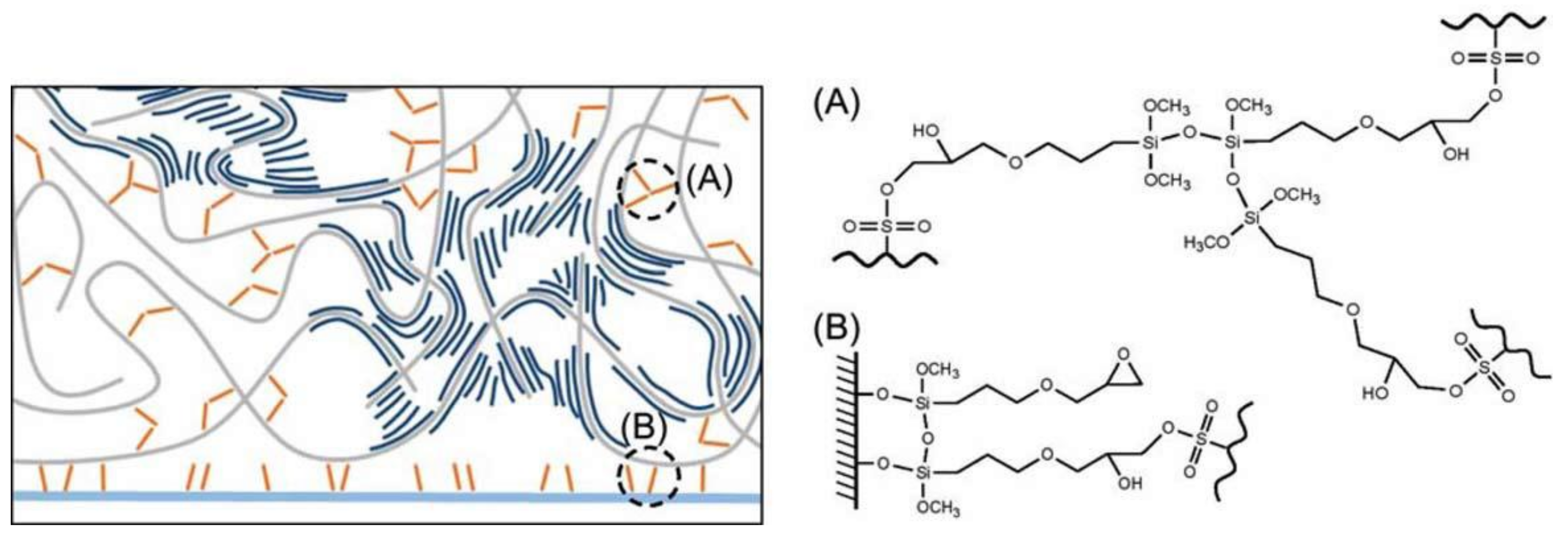
3.2.2. Enhancement of Adhesion Properties of PEDOT:PSS

A major drawback in the use of PEDOT:PSS in biological sensors is its poor mechanical stability in long-term applications. Some studies were performed to increase the adhesion of PEDOT:PSS to the substrate to resist mechanical stress, notably immersion in aqueous media. Two pathways can be cited. The first one and probably the most used is the addition of a cross-linker such as (3-glycidyloxypropyl)trimethoxysilane (GOPS) or divinyl sulfone (DVS). In 2017, Hakansson et al. [82] showed that the addition of a small amount of GOPS in a PEDOT:PSS solution (0.1 v/v %) prevents the delamination of PEDOT:PSS on a glass substrate. The involved mechanism is a triple cross-linking: GOPS-GOPS, GOPS-PSS and GOPS-glass (Figure 8). Authors showed that PEDOT:PSS resists ultrasonication during more than one hour in comparison with the untreated deposition where PEDOT:PSS delaminates in less than 2 min.
However, the use of GOPS as cross-linker decreases the conductivity of PEDOT:PSS due to the formation of a siloxane network. To prevent this effect, Mantione et al. [83] used DVS in combination with ethylene glycol to create an insoluble film at low temperature curing (50°C). Converse to GOPS, the amount of added DVS does not influence the conductivity of PEDOT:PSS. In addition, DVS cross-linked PEDOT:PSS films show perfect results in biocompatibility assays.
To increase the adhesion of PEDOT to substrates, in particular for metallic or ITO substrates, another strategy was employed first by Wei et al. [84] consisting in the chemisorption of EDOT-acid molecules on activated ITO surfaces, followed by electropolymerization of the EDOT moieties. After 2 min of ultrasonication, PEDOT stayed stable on the ITO surface. The same process was followed by Ouyang et al. [85] in 2017, by electrografting EDOT-NH2 followed by an electropolymerization of the EDOT moieties. Such PEDOT coatings turned to be stable after 1 h of ultrasonication compared to pure PEDOT which delaminated on ITO after a few seconds.
To improve adhesion onto gold surfaces without using any cross-linker or adhesion layer, Pranti et al. [86] performed the deposition of PEDOT:PSS onto an iodine-etched gold surface, which creates a rough porous surface. Then, the electropolymerization of EDOT in presence of PSS allows the formation of the polymer into the pores leading to the formation of a PEDOT:PSS layer with strong mechanical bond. Ultrasonication tests show a conservation of the PEDOT:PSS layer after more than 10 min.
In the following paragraphs, the most common techniques employed for the fabrication of OECT-based biosensors are reviewed.

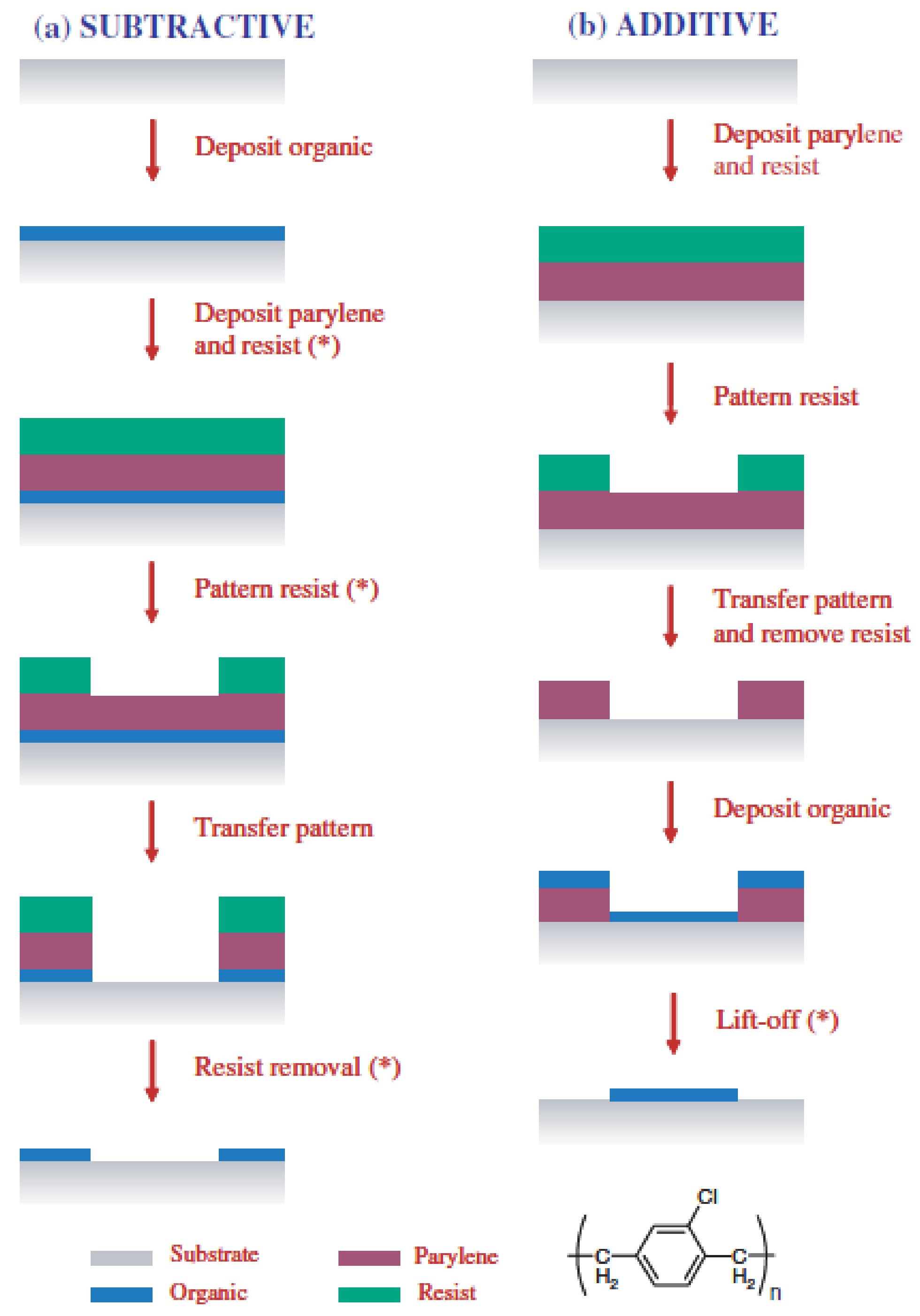
3.3. Fabrication Techniques

3.3.1. Spin-Coating

Spin-coating is by far the most frequently utilized fabrication technique. Two main different approaches may be distinguished [87], namely a top-down or subtractive approach where PEDOT:PSS is first deposited on the substrate and subsequently patterned, and a bottom-up or additive approach in which PEDOT:PSS is spin-coated on a pre-patterned layout (Figure 9).
Prior to spin-coating, additives are often added to the PEDOT:PSS suspension to increase the final film electrical conductivity (such as ethylene glycol or dimethyl sulfoxide) or to improve film formation and adhesion (such as dodecylbenzenesulfonic acid (DBSA), (3-glycidyloxypropyl) trimethoxysilane (GOPS) or alkylbenzenesulfonic acid (ABSA)), as discussed in the previous sections.
In most cases the channel final thickness is approximately 100 nm but values larger than 400 nm were also reported [88]. After spin-coating, devices are thermally annealed (T ≥ 125 °C) for several tens of minutes to promote solvent evaporation; annealing may be performed either in air or in inert atmosphere. Two-step annealing processes, with increasing temperatures, are also reported. In a few cases, after thermal annealing, devices were soaked in deionized water to remove loosely bound polymer chains or excess additives.
The most important characteristics of spin-coating fabrication processes are summarized in Table 1.

3.3.2. Screen-Printing

Screen-printing has also been successfully used for the fabrication of OECTs-based biosensors. In 2015, Scheiblin et al. [111] reported on the fabrication of glucose and lactate sensors on a flexible, plastic substrate (polyethylene naphthalate, PEN). These devices were obtained by using three different inks: PEDOT:PSS (fabrication of the transistors active channel, final thickness of 500 nm), poly(vinylidene fluoride) (PVDF, a dielectric material used to insulate the electrical contacts and define the contact area between the channel and the electrolyte, final thickness of 2 μm) and finally a silver-based ink (used to realize the electrical contacts, final thickness of approximately 8 μm). After printing, each layer was annealed at 130 °C (for PEDOT:PSS) or at 100 °C (for PVDF and silver contacts) for a few minutes (Figure 10). More recently, Contat-Rodrigo et al. [112] employed screen-printing for the fabrication of an OECT-based sensor for the detection of ascorbic acid in food. In this case, the whole device (active channel, gate, source and drain contacts) were realized by screen-printing a PEDOT:PSS ink on a flexible, polyester substrate. After printing, the transistors were annealed in air at 100 °C for 10 minutes; the printed layers had a final thickness of about 55 μm.

3.3.3. Inkjet-Printing

Inkjet-printing has recently attracted considerable attention for the fabrication of OECTs-based sensors, mostly because it is a digital technique not requiring a physical printing master. It allows the utilization of relatively small quantities of inks and be easily adapted to different sizes of production scale, varying from rapid circuit prototyping on small-scale substrates to large-scale, large-area production [113].
Thus far, inkjet-printing has been successfully used for the deposition of a suspension of polypyrrole nanoparticles and glucose oxidase [114] or a suspension of PEDOT:PSS, glucose oxidase and horseradish peroxidase [115], in both cases for the detection of glucose, or monoclonal murine antibodies for the fabrication of immunosensors [116]. Despite these encouraging results, to our best knowledge, no examples of inkjet-printed OECTs for the detection of metabolic analytes have been reported until now.

3.3.4. In-Situ Polymerization

The OECT active layer can be deposited on the top of the source and drain electrodes also by performing an in-situ polymerization. Sukeerthi et al. [117] demonstrated the possibility of depositing a layer of polyaniline between interdigitated source and drain electrodes starting from a solution containing 0.1 M aniline in 0.5 M H2SO4; the electrode potential was cycled between −0.2 and +0.8 V vs. SCE. Glucose oxidase (GOx), for glucose detection, was also immobilized into the polymer matrix by electropolymerization from pH 4.0 phthalate buffer containing 0.1 M aniline and 250 units mL−1 GOx. More recently, Kanungo et al. [118] developed a procedure for the fabrication of microtubule sensors for the detection of glucose, urea and triglycerides based on electropolymerized poly(styrene sulfonate)-polyaniline (PSS-PANI) composites synthesized within the pores of track-etched polycarbonate membranes. First, two gold stripes were thermally evaporated on the opposite faces of each membrane. These stripes were then used as electrodes for the polymerization of the active layer. After deposition of the active layer, glucose oxidase was immobilized on the conducting polymer microtubules again by electropolymerization while urease and lipase (for urea and triglyceride detection, respectively) were physisorbed on the active layer. Devices were then used in a transistor configuration; the two gold stripes acting as source and drain electrodes and a reference electrode used as gate. Very recently, Wang et al. [119] demonstrated that in-situ polymerization can be also performed on non-conventional substrates, such as fibers. The authors utilized Nylon PA6 yarns which were covered with a thin layer of graphene oxide (GO) which was then chemically reduced to graphene (rGO) (Figure 11).
On such yarns, in-situ polymerization of polypyrrole (PPy) was then performed. Each OECT-based glucose sensor was then assembled by placing two yarns in a cross-junction configuration and connected by an electrolytic gel containing different glucose concentrations. The bottom yarn acted as the transistor channel while the top yarn (functionalized with GOx) acted as the gate electrode.
Vapor-phase polymerization (VPP) has also been successfully used for the fabrication of OECTs-based glucose sensors by Kim et al. [120] As reported in this paper, the authors prepared an oxidant solution containing Fe(III)-tosylate (dissolved in isopropyl alcohol) and spin-coated it on a glass substrate. The substrate was then placed inside a polymerization chamber containing a hot plate filled with a small amount of a 3,4-ethylenedioxythiophene (EDOT) solution. After polymerization (7 min at 70 °C), the PEDOT layer was washed with ethanol to remove the remaining oxidants. A small PDMS well was finally glued on the substrate to confine the solution to be tested (PBS at pH = 7.4, containing 3.6 mg mL−1 of glucose oxidase) on the transistors channel. The transistor configuration was eventually completed by dipping a Pt wire, acting as gate electrode, into the electrolytic solution.

3.3.5. Soaking

If the transistor substrate is represented by natural cotton fibers, deposition of the active layer can be simply achieved by soaking the yarns into a suspension containing the polymer to be deposited. Coppedè et al. [121] followed this method to fabricate OECTs-based adrenaline biosensors. They used a commercial PEDOT:PSS suspension, modified with ethylene glycol (20%) and dodecyl benzene sulfonic acid (12%) to increase electrical conductivity and reduce solubility in water, in which cotton yarns where soaked for 5 min, followed by baking at 150 °C for 3 h on a hot plate. This process resulted in the formation of a homogeneous PEDOT:PSS layer (approximately 50 nm thick) all around the fiber. Such yarn, acting as the transistor channel, was then woven into a fabric with a thin Pt wire, acting as gate electrode, also woven in its proximity. The electrolytic bridging between the two yarns was performed by gently pipetting a few drops of electrolytic solution (0.1 M NaCl with 1 mM adrenaline) in the space between the two yarns. Very recently, Battista et al. [122] used the same method for the fabrication of biosensors able to detect L-tyrosine. Cotton yarns were treated exactly as described in the previous reference but, before weaving, they were immersed for 1 h in a solution of 0.1 M sodium citrate buffer containing 30 U mL−1 of recombinant POXA1b (rPOXA1b) laccase at isoelectric point (pH 6.7). The fibers were subsequently rinsed with the same buffer solution and stored at 4 °C before use. The sensing system was then fabricated by weaving a functionalized cotton yarn and a thin Pt wire next to it into a substrate fabric. Sensing measurements were then performed by joining the two wires with a small drop of aqueous solutions (0.1 M sodium citrate buffer, pH 3.0) at different concentrations of L-tyrosine (between 10−8 and 10−3 M).
Below (Table 2) are summarized some parameters of PEDOT:PSS inks (commercial or homemade) discussed in this section.

4. Applications

In addition to the few illustrative examples gave in the previous sections, OECTs have been used to investigate a large variety of bio-assemblies, including nucleic acids, proteins in general, antibodies in particular, antigens, bilipidic membranes, small oxidable biomolecules. Some approaches use enzymes, and some others do not.

4.1. Enzymatic Biosensors
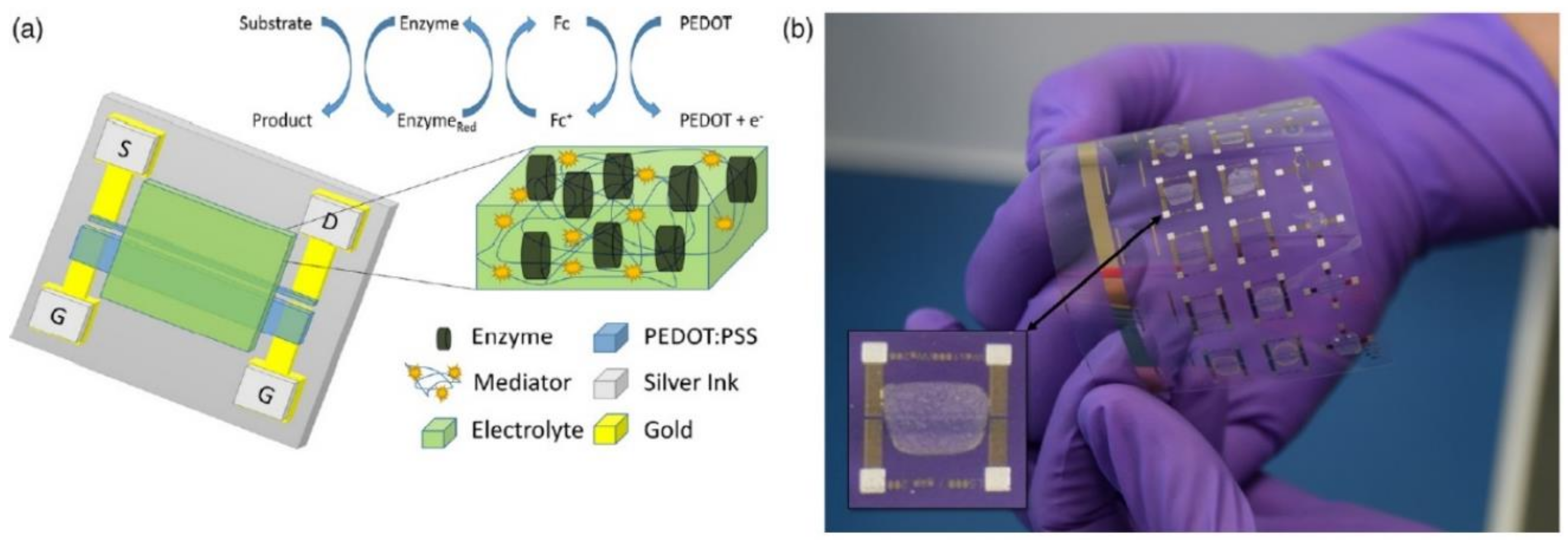
4.1.1. Glucose

Glucose sensing and especially continuous glucose monitoring is of crucial importance. Indeed, for example, rather than having to manually control their blood glucose level several times a day, there is a specific need for diabetic patients to have a permanent and continuous automatic glucose monitoring device that would entail automatic insulin injection. Not only would such automatization considerably facilitate patients’ life, but it would also prevent thousands of deaths each year. Even if full automation is still a dream for diabetics, continuous glucose monitoring is now available on the market. All OECTs dedicated to glucose monitoring use glucose oxidase as a specific recognition element. This D-glucose-specific enzyme oxidizes D-glucose in D-gluconolactone, producing H2O2 at the same time; its redox center is concomitantly reduced and recycled using molecular oxygen present in the medium. D-glucose quantification is based either on the reduction of its own concentration in the solution under test or on the quantification of H2O2 that appears as a result of its oxidation.
Historically, the first enzymatic glucose biosensor was developed by Updike and Hicks, using GOx and a conventional oxygen electrode [50]. As comprehensively reviewed in the article by Lin and Yan [123], the very first investigations of glucose sensors on devices which were close to OECTs, even if closer to conductimetric devices because of the absence of gate as third contact, were reported by Hoa et al. in 1992 [124] and Bartlett et al. in 1993 [125]. However, one can consider that Zhu et al. described the first OECT for glucose sensing based on PEDOT:PSS in 2004, with a three-terminal device comprising a platinum gate [89]. In the presence of GOx and glucose, gluconic acid and H2O2 were produced; the latter was oxidized at the platinum gate electrode, which consequently reduced PEDOT+ in the channel and produced a decrease of the drain current ID. Since this seminal work, most of the OECT architectures towards glucose sensing have been focused on the improvement of several parameters such as sensitivity, selectivity (principally towards ascorbic and uric acids), and lowering the detection limit. Furthermore, obtaining a linear response within the standard human glucose concentrations range, whether in blood (4 to 7 mM) or sweat (5.6 µM to 2.2 mM), was also a target.
If the previous example used GOx in solution, in almost all recent publications, GOx was immobilized within the device structure, preventing enzyme leakage and decrease of signal over time. For example, Malliaras and coworkers developed a screen-printed OECT for both glucose and lactate sensing [111]. Rather than being present in solution, both the ferrocene mediator, which was covalently bound to chitosan, and the GOx were integrated into the sol-gel electrolyte which prevented their further deterioration during measurements. Glucose was detected in a linear range from 23 µM to 2 mM, values almost compatible with the glucose concentration found in human sweat. The response time was within the minute range (a maximum of 350 seconds was observed). On the other hand, neither the stability during storage, nor the selectivity, especially in the presence of ascorbic acid, of this device was assessed.
With the objective to improve the sensor’s sensitivity, Liao et al. described an OECT where they introduced graphene into the gate electrode (chitosan-graphene/GOx/Pt) [54]; a detection limit of 10 nM was achieved. In a previous work, [53] the same authors achieved one of the best detection limit described so far (5 nM) by modifying the gate electrode with GOx and nanomaterials such as PtNPs and multiwalled carbon nanotubes (MWCNTs), but their OECT suffered from a poor linearity, which is a major drawback for practical applications. In a more recent work, they solved this drawback and their OECT showed a linear response range for glucose from 10 nM to 1 µM. The linearity and selectivity of the device was enhanced with the addition of chitosan that helped the immobilization of GOx on the gate electrode and acted as an exclusion membrane limiting the glucose flux and excluding, at the same time, some interferents such as uric and L-ascorbic acids [126].
In 2015, Liao and co-workers focused on the gate electrode nature, replacing the costly Pt gate electrode by cheaper TiO2 nanotubes arrays (TNTAs) decorated by Pt nanoparticles [90]. Pt nanoparticles deposited onto TNTAs had previously proved themselves useful when employed for H2O2 sensing; indeed, they were 10 times more sensitive compared to TNTAs alone [127]. This could be due to good electron-transfer behavior and large surface area [128]. The PtNPs were deposited on the TNTAs surface, then the Pt NPs/TNTAs electrodes were immersed into a GOx solution and then in a Nafion solution overnight (Figure 12a). Due to the TNTAs architecture, this protocol allowed to immobilize more GOx than on non-modified surfaces. The detection limit was 100 nM, and this OECT showed a linear response from 100 nM to 5 mM. Among other advantages, this OECT showed an excellent selectivity against both ascorbic and uric acids, and a good reproducibility and stability for at least ten days. This work showed that OECTs can be of interest for glucose measurements in real samples.
In 2015, Welch and co-workers described an OECT architecture where the GOx was covalently linked to the transistor via polymer brushes through the establishment of carbon-nitrogen bounds (Figure 12b) [129]. These covalent bonds were the results of the reaction between the primary amine of the GOx with the epoxy groups borne by the poly(-glycidyl methacrylate: poly (2-hydroxyethyl methacrylate) (PGMA:PHEMA) polymers. Those nanopolymer brushes were grafted on the plasma-activated PEDOT:PSS surface via gas phase functionalization which enabled to keep intact the conductivity of the OSC (>90% of its initial conductivity versus ca. 3% with a standard solution functionalization). The article described the optimal conditions for plasma activation of PEDOT:PSS in order to control its conductivity and the length of polymer brushes. These polymers are compatible with biological media and PHEMA prevents non-specific adsorption. The authors demonstrated the importance of covalent bonds between the GOx and the polymers, which brought stability with time: OECTs retained 100% of their signal after 100 days, compared to a few days for non-covalently bound GOx.
In 2015, Liao et al. [99] reported on the fabrication of a flexible and highly selective enzymatic OECT-based sensor using a gate electrode functionalized by an alternation of positively charged (a PANI film) and negatively charged (graphene flakes/Nafion) bilayer films (Figure 13). The authors compared the sensitivity of their device towards several analytes (uric acid, lactic acid, glucose, cholesterol and H2O2) compared to a more classical bare Pt gate electrode. They showed that the nature of the electrode participated in the decrease of the detection limit for most analytes, of around three orders of magnitude except for H2O2. This GOx-GO/PANI/Nafion/graphene/Pt gate electrode was used to detect glucose with a very low detection limit of 30 nM.
In a very recent paper, Ji and Chan [130] described the fabrication of an OECT integrated with a microfluidic device. First, PtNPs then GOx/chitosan were sequentially deposited onto the gate electrode. A low detection limit of glucose (0.1 µM) was achieved thanks to PtNPs catalytic oxydation of H2O2 on the gate. The use of a microfluidic channel presented several advantages such as a low analyte consumption (30 µL) and a very short detection time (1 min), of real interest for a real-time, non-invasive and portable glucose sensor.

4.1.2. Lactate

The detection of lactate is of great interest for monitoring several biological mechanisms. Lactate is a relevant indicator of the physiological response to exercise and is a marker in diseases such as diabetes and cancer. The concentration range in sweat is comprised between 9 and 23 mM [131].
Khodagholy et al. [97] fabricated an OECT with a ionogel solid-state electrolyte incorporating poly(N-isopropylacrylamide-co-N,N′-methylene-bis(acrylamide)), an ionic liquid (1-ethyl-3-methylimidazolium ethylsulfate) (the ionic liquid was assumed to bring a high conductivity), a ferrocene redox mediator, and an immobilized lactate oxidase. The detection of lactate in a relevant physiological range was achieved from 10 to 100 mM. In another study, Braendlein et al. [91] reported the ex vivo sensing of lactate levels produced from normal cells and malignant cells culture with a limit of detection of 10 µM. The biosensor consisted of two differently biofunctionalized OECTs integrated into a Wheatstone bridge. Lactate oxidase was immobilized into the gate electrode of the sensing transistor while a nonspecific protein (bovine serum albumin) was used for the reference OECT ensuring an inherent background subtraction and reducing interferences from the complex cell culture media. Pappa et al. [132] also developed a multiplexed OECT platform integrated within a portable “finger- powered” microfluidic device for the simultaneous detection of three clinically relevant biomarkers in human saliva, with high sensitivity and selectivity. The gate electrode biofunctionalization of each transistor in the platform was performed with a blend of PEDOT:PSS:PVA polymers and by the immobilization of either glucose oxidase, lactate oxidase (LOx), or cholesterol oxidase (ChOx) for the respective detection of glucose, lactate, or cholesterol. The enzyme has been integrated into a chitosan supporting matrix in the presence of ferrocene redox as a mediator, thus lowering the working potential of the electrodes, and reducing background signal. The OECT array exhibits limits of quantification (LOQ) of 10 μm for glucose, 50 μm for lactate, and 10 μm for cholesterol, corresponding to the physiological ranges in saliva.
Scheiblin et al. [111] reported screen-printed biosensors on a flexible PEN substrate for glucose and lactate sensing in human sweat. The detection range of the printed sensors extended from 0.1 to 2.3 mM, i.e., the low end of the level range of lactate in sweat, the high end of the range only being accessible by dilution. The modification of the gate electrode of an OECT with poly(N-vinyl-2-pyrrolidone)-capped platinum nanoparticles (PtNPs) was reported to enhance the sensitivity and to improve the detection limit of glucose and lactate down to 10−7 and 10−6 M, respectively [133]. The authors also developed a multisensing device by integrated two single OECTs with two separate microfluidic channels in one chip to reduce the volume of analyte and increase the detection speed. Strakosas et al. also took advantage of the catalytic efficiency of platinum-modified gate electrode [106]. A negatively charged polymeric hydrogel encompassing the enzyme and covalently bound on top of the gate was reported to lower the diffusion of the glucose and lactate analytes thus extending the linearity ranges, and to block negatively charged interfering species from the complex media, i.e., in vitro live cells in the authors’ study.

4.1.3. Other Analytes Detected Enzymatically
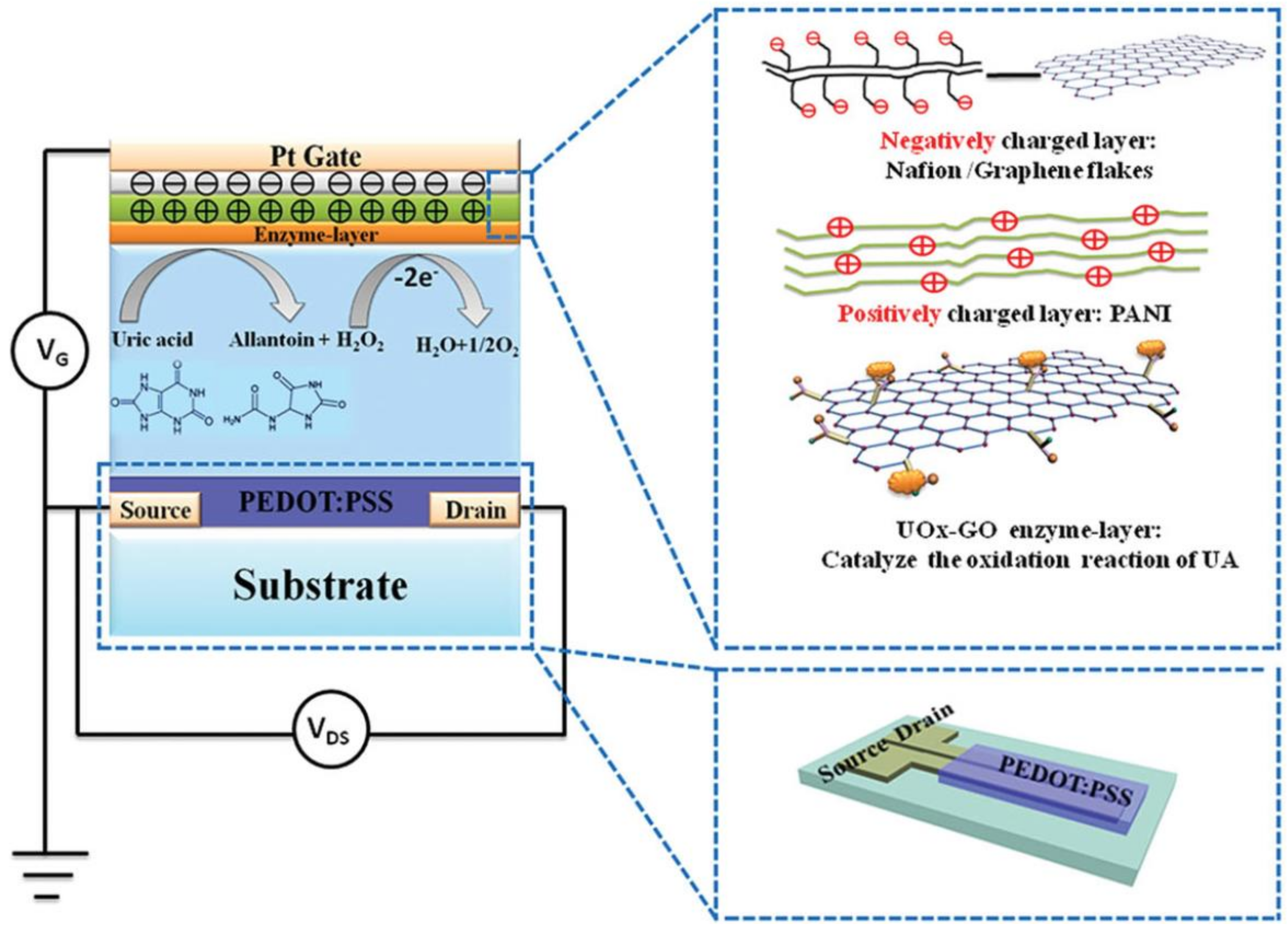
Uric acid

Uric acid (UA) is the end-product of purine metabolism in human body. The basal concentrations of uric acid in physiological samples vary from 10−7 to 10−3 M depending on the matrix [134].
Liao et al., in the same article where they reported glucose sensing [99], also reported uric acid sensing, using the enzyme uricase immobilized on the gate electrode. Through glutaraldehyde cross-linking, a limit of detection of 30 nM was measured, which was lowered to 10 nM using an uricase:graphene oxide mixture. The OECT showed good linearity in a very wide range of UA concentrations, between 100 nM and 500 µM. The authors reported no interference caused by dopamine and ascorbic acid.

Tyrosine

Tyrosine (4-hydroxyphenylalanine, Tyr) is a natural phenolic amino acid and plays a key role in various biological processes as a precursor in biosynthetic pathways of neurotransmitters, hormones, alkaloids, natural phenols and pigments [135,136].
A textile-based wearable biosensor for direct detection of tyrosine, without the use of any electron mediator, was described by Battista et al. [122]. Laccase oxidase was non-covalently immobilized onto PEDOT:PSS-coated cotton yarn and the authors claimed direct electron transfer from the enzyme to PEDOT; the analytical performances were relatively low, however, with a detection limit around 10−6 M tyrosine. Another more sensitive tyrosine OECT sensor was fabricated by Wang et al. [137]. The Au gate electrode was modified by a nanocomposite consisting of gold nanoparticles (AuNPs), poly(diallyldimethylammonium chloride) (PDDA) and multi-walled carbon nanotubes. This OECT displayed a linear response to Tyr over a wide concentration range of 0.3 μM to 10 μM, with a detection limit of 10 nM (in PBS).

4.2. Enzyme-Free Biosensors

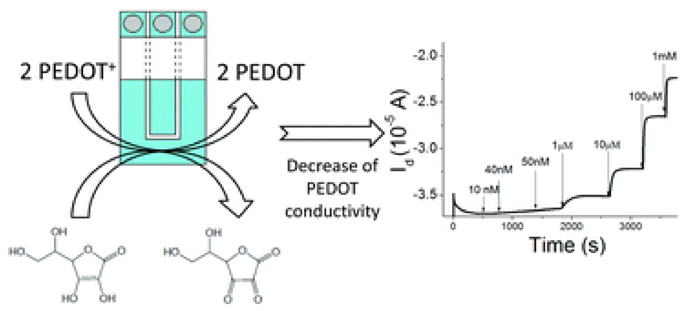
4.2.1. Ascorbic Acid

The antioxidant activity of ascorbic acid (AA, also called vitamin C) can be used for the prevention and treatment of scurvy, common cold, mental illness, cancer, and AIDS. The concentration in human tissues is between 0.04 and 4 mM, while in food rich in vitamin C it is in the range of 0.005–2 mM [138,139]. The detection of AA with high sensitivity is then needed for foods, drugs, and cosmetic applications.
Gualandi et al. developed an all-PEDOT:PSS OECT sensor for ascorbic acid detection [57], without the presence of either enzyme or other redox mediators; ascorbic acid was directly electrooxidized at the gate electrode. A limit of detection of 13 nM and a sensitivity of 4.5 × 10⁻⁶ A decade−1 have been reached, with a linearity domain between 10−6 and 10−3 M.
Contat-Rodrigo et al. [112] investigated the effect of the geometry of the OECT on the transistors performance. All-PEDOT:PSS screen-printed OECTs exhibited higher sensitivity, larger modulation and better LOD values (80 µM) with a small channel and gate areas ratio (smaller gate electrode than the channel). For low AA concentrations (10−8 M to 10−5 M) OECTs work in the non-Faradaic regime, where the polymer doping is coupled with the charging of an ionic double layer. For higher concentration (up to 10−2 M) the OECTs operate in the Faradaic regime where doping/dedoping is coupled with the electro-catalytic oxidation of ascorbic acid by PEDOT:PSS at the gate electrode.
Very recently (2018), a molecularly imprinted polymer (MIP)-based OECT sensor was designed to detect ascorbic acid [110]. The adsorption and the oxidation of AA occurs on the MIP-modified gate electrode, thereby improving the selectivity. A LOD of 10 nM and a sensitivity of 75 μA of channel current change per decade (within the range 1 μM–100 μM) were measured. The addition of common interferents (Asp, Gly, Glu, UA, H2O2, etc.) gives rise to weak changes of the effective gate voltage and therefore weak drain current changes.

4.2.2. Dopamine

Dopamine is one the most important neurotransmitters in biological organisms [140]. The selective sensing of dopamine is of great significance in the diagnosis of neurological diseases such as Parkinson’s disease, autism, and schizophrenia. However, the sensitivity and selectivity of the electrochemical detection of dopamine suffer from the low clinical concentration in human body fluids (in the range of micromolar for urine and nanomolar for plasma) and the presence of endogenous interferences such as uric acid and ascorbic acid.
Liao et al. have reported OECTs showing high sensitivity within a wide linear range from 5 nm to 1 µM and a LOD down to 5 nM [100]. The selectivity was improved by the modification of the Pt gate with biocompatible polymers such as Nafion and chitosan. Since Nafion and chitosan (pKa = 6.4) are negatively charged in PBS (pH 7.4), the diffusion of anionic electroactive compounds such as AA (pKa = 4.2) and UA (pKa = 5.2) to the gate electrode is significantly hindered. The electrostatic repulsion between the interference substance and the film gives rise to an improved selectivity towards dopamine. The introduction of graphene-based materials leads to enhanced electrochemical reactivity and enlarged active surface due to π–π interactions between the 2D planar hexagonal structure of graphene and the phenyl group of dopamine, facilitating the electron transfer and the oxidation of dopamine (Figure 14).
The influence of different gate electrode materials (graphite, Au, Pt electrodes and modified graphite or Pt electrodes with MWCNT-chitosan hybrid) and the operating voltage on the performances of OECTs as dopamine sensors have been investigated. Tang et al. [96] reported the highest sensitivity with a Pt gate electrode and a gate voltage of 0.6 V. The limit of detection was lower than 5 nM with a broad linear region from 50 nM to 3 µM.
Tybrandt et al. used the OECT working principle to amplify the fast scan cyclic voltammetry (FSCV) signals to measure dopamine concentrations in the 10 µM range [141]. Fast scan cyclic voltammetry (FSCV) is an electrochemical technique commonly used in neurosciences for spatiotemporal measurement of the concentration of dopamine and other electroactive species [142]. FSCV involves a very high scan rate (50 to 400 V s−1) and a wide bandwidth for low currents and is generally executed inside a Faraday cage. The on-site amplification of the OECT allows the reduction of the electrical noise and enables FSCV measurements in an unshielded environment. A similar motivation guided Gualandi et al., who described an all-PEDOT:PSS OECT dopamine sensor displaying a limit of detection of 6 μM in the presence of interference compounds (AA and UA) [105]. The authors took advantage of a potentiodynamic technique to separate the redox waves associated to different analytes and therefore to selectively identify and determine the contributions of different analytes to the OECT electrical output signal through a linear scan of the gate potential. The sensitivities and the LOD were comparable or even higher than those obtained by differential pulse voltammetry (DPV). Similarly, Wang et al. [143] demonstrated that alternative current (AC) measurements of OECT-based dopamine biosensors exhibit several advantages compared to direct current DC methods such as faster response time (up to 10−5 s), the ability to collect more information (both transconductance amplitude and phase of channel currents), more stable current and lower LOD down to 1 nM by introducing a lock-in amplifier (Figure 15).

4.2.3. Adrenaline

The detection of adrenaline (or epinephrine), a neurotransmitter and a hormone, is of great interest for medical and anti-doping purposes. Adrenaline level in human plasma is very low (0.2 nM) [141].
Coppedè et al. [121] developed an e-textile integrated biosensors encompassing a cotton yarn functionalized with PEDOT:PSS, a Pt-wire used as gate electrode and human sweat as electrolyte (Figure 16, see also Section 3.3.5). The detection of adrenaline concentration above 1 µM has efficiently been performed. Coppedé et al. have also developed a super-hydrophobic OECT device in which a finite number of micro-electrodes are independently controlled for site-selective measurements of analytes based on their size and charge [103,104]. The competition between Marangoni convective flows and diffusion within the volume of a drop of solution deposited on the super-hydrophobic OECT enables a time- and space-resolved separation of biological species with high sensitivity, selectivity and reliability. The sensing of a solution containing both CTAB and adrenaline has been demonstrated. Finally, Mak et al. [102] fabricated epinephrine sensors where the gate electrode was modified with carbon nanomaterials, including single-walled carbon nanotubes (SWCNTs), graphene and graphene oxide, which can promote electron transfer reactions and enhance the electrocatalytic activity of the gate electrodes. A detection limit down to 0.1 nM was measured with a gate modified with Nafion and SWCNTs.

4.2.4. Gallic and Sialic Acids

OECTs were applied to quantify less investigated analytes such as total polyphenol content (TPC) from real tea samples. For example, Xiong et al. [109] developed a high sensitive OECT sensor for the detection of gallic acid (3,4,5-trihydroxybenzoic acid) where the Au gate electrode was modified with poly(diallyldimethylammonium) chloride (PDDA) and multiple carbon nanomaterials (MWNTs, graphene, and graphite oxide). The functionalization of the gate electrode with PDDA-carbon nanomaterials composites improved the sensitivity of the OECTs through the enhancement of the electron transfer and the electrostatic attraction between gallic acid and PDDA (Figure 17). While OECTs with either the graphene-PDDA or GO-PDDA modified gate exhibited a detection limit of 30 nM, MWNT-PDDA modified gate showed the best detection limit of 10 nM, 10 times better than that of the OECT with the bare Au gate.
Sialic acid is a monosaccharide with a nine-carbon backbone and is overexpressed in cancer cells membranes. OECT sensors encompassing screen-printed carbon source and drain electrodes on flexible substrates and poly (3-aminophenylboronic acid) (PABA)-modified glass carbon (GC) gate electrodes have been tested to detect free sialic acid and identify cancer cells (human cervical cancer, HeLa) [107] (Figure 18). The selectivity of the sensor relies on high binding constant between phenylboronic acid and sialic acid. The LOD for sialic acid and malign cells was ca. 8 µM and 4.0 × 10³ cells mL−1, respectively.

5. Patents and Commercialized OECT-Based Biosensors

Besides published articles on the topic of OECTs for sensing of metabolites, several patents have been deposited since the first developments of these devices. This is a good indicator of the degree of development and maturation of this technology.
The first patent application concerning OECTs was registered in 2001 by D. Nilsson, M. Berggren and J.P.O. Svensson for the company Acreo Ab [144].
The sensor device comprised the basic OECT structure, i.e., source and drain contacts, a gate electrode, an electrochemically active material contacting both in-between and an electrolyte in direct contact with both the gate and the electroactive material. Applications were limited to ion or humidity sensing and did not cover sensing of small organic molecules. A related patent was submitted the same year and finally accepted years later (2009) [145], where such a device was claimed to be used as electromagnetic tag with source and drain connected to two antennas. A related patent was issued more recently, which improved the design of the previously described OECT [146] but for both patent, claims did not concern sensing of molecules.
More recently (2013), the Polytechnic University of Hong-Kong submitted a patent, issued in 2015 [147], where an OECT was claimed to be used to detect biological molecules in physiological environment. Practically, this patent suggested functionalizing the gate electrode with biomolecules such as DNA or proteins such as enzymes. An application of glucose sensing was claimed and described in detail, using a Pt gate electrode. Its originality relied on its cylindrical geometry around a filament that could be a textile yarn. The same authors proposed a related patent, issued in 2017, which is much more precise on the application for a non-invasive glucose sensor [148]. They proposed a structure in which a part of the gate electrode can be modified with a nanomaterial to increase the sensitivity. For example, they proposed a bulk Pt gate electrode covered with a composite of carbon nanotubes, chitosan and glucose oxidase, or where multi-walled carbon nanotubes (MWCNTs) were replaced by Pt nanoparticules. The patent did not propose an original transistor architecture; the limit of detection claimed was low (0.5 µM with MWCNTs-CHIT/GOx/Pt, 5 nM with CHIT/GOx/Pt-NPs/Pt) but the stability was very poor (30% loss after eight days) and the linearity very poor as well (up to 1 mM glucose). On the contrary, approximately at the same period, the Korean Institute of Machinery and Materials deposited a patent describing an OECT made of linear contacts that can be textile yarns, covered by a conductive layer and embedded within a semiconducting material. Even if the inventors cite chemical sensing as a potential application of such a device, such an application is not among claims. [149].
Related to textile, N. Coppedè and co-inventors deposited in 2016 a filament-based OECT that can be put on clothes such as sport tee-shirts, aiming at measuring body parameters in perspiration through enzymatic reactions, such as lactic acid content of the sweat of an athelete [150]. Claims are not supported by experimental results, however.
Last, a method of fabrication of OECT structures was deposited and accepted in 2016 [151], proposing to make devices of any shape and at high resolution without the need for mechanical or laser cutting, but no claim concerned sensing.
This short review of the accepted patents clearly shows that, compared to classical electrochemical sensing devices, OECTs have been poorly patented up to date for (bio)sensing applications and that avenues are still open for the industrial development of these devices, in particular if there are opportunities to integrated sensing devices in non-conventional substrates like clothes.

6. Conclusions

In the field of electrochemical sensors, potentiometric sensors came first. Due to their intrinsic limitation in terms of sensitivity, amperometric sensors followed soon. A huge literature covers amperometric sensors for detection of small molecules in water, from direct electrooxidation of these molecules on an electrode to multi-step transduction of specific molecular recognition events (immunological, enzymatic, or using DNA aptamers). To reach high sensitivities and low limits of detection, amperometry must be assisted by amplification strategies, often based on enzymatic labeling. Electrochemical transistors, and particularly organic ones, take advantages of their mixed ionic and electronic processes. It is now clear that the most efficient way to use OECTs as chemical sensors was to use the gate as the sensing element. It can act both as a potentiometric sensor (changes in gate potential triggering changes in source-drain current) and as an amperometric sensor (where electronic transfers occurring on the gate lead to a gate current which is amplified into a drain current).
On the one hand, today, the concepts driving OECTs are well-known. On the other hand, amperometric sensors have been extensively reported and are mature. The approach which consists in merging the two is now well described, even if significantly less investigated than standard amperometric sensors. One potential development of OECTs for sensing lies in the absence of reference electrode, in the freedom offered by their architecture which allows easy fabrication processes where all parts of the device can be made of the same material (i.e., PEDOT:PSS for contact electrodes as well as for the active semiconductor) and deposited on various substrates, including conformable ones, plastics, textiles, and even paper. A related axis of development is the fabrication method. Instead of subtractive methods, additive methods such as printing are particularly well adapted to fabricate OECTs, which makes them economically attractive in industrial processes and even more easily accessible at the research scale than costly methods involving clean-room technologies. The last axis is, of course, the materials themselves; PEDOT:PSS is today the gold standard but other materials, still to be investigated, may be more conductive, more mechanically resistant or more easily functionalizable than PEDOT or PSS.

Conflicts of Interest

The authors declare no conflict of interest.

References

  1. Kergoat, L.; Piro, B.; Berggren, M.; Horowitz, G.; Pham, M.C. Advances in organic transistor-based biosensors: From organic electrochemical transistors to electrolyte-gated organic field-effect transistors. Anal. Bioanal. Chem. 2012, 402, 1813–1826. [Google Scholar] [CrossRef] [PubMed]
  2. Torsi, L.; Magliulo, M.; Manoli, K.; Palazzo, G. Organic field-effect transistor sensors: A tutorial review. Chem. Soc. Rev. 2013, 42, 8612–8628. [Google Scholar] [CrossRef] [PubMed]
  3. Rivnay, J.; Inal, S.; Salleo, A.; Owens, R.M.; Berggren, M.; Malliaras, G.G. Organic electrochemical transistors. Nat. Rev. Mater. 2018, 3, 17086. [Google Scholar] [CrossRef]
  4. Matsue, T.; Nishizawa, M.; Sawaguchi, T.; Uchida, I. An enzyme switch sensitive to NADH. J. Chem. Soc. Chem. Commun. 1991, 1029–1031. [Google Scholar] [CrossRef]
  5. Bartlett, P.N.; Birkin, P.R. A Microelectrochemical Enzyme Transistor Responsive to Glucose. Anal. Chem. 1994, 66, 1552–1559. [Google Scholar] [CrossRef]
  6. Bartlett, P.N. Measurement of low glucose concentrations using a microelectrochemical enzyme transistor. Analyst 1998, 123, 387–392. [Google Scholar] [CrossRef]
  7. Ebisawa, F.; Kurokawa, T.; Nara, S. Electrical properties of polyacetylene/polysiloxane interface. J. Appl. Phys. 1983, 54, 3255–3259. [Google Scholar] [CrossRef]
  8. Laurs, H.; Heiland, G. Electrical and optical properties of phthalocyanine films. Thin Solid Films 1987, 149, 129–142. [Google Scholar] [CrossRef]
  9. Assadi, A.; Gustafsson, G.; Willander, M.; Svensson, C.; Inganäs, O. Determination of field-effect mobility of poly(3-hexylthiophene) upon exposure to NH3 gas. Synth. Met. 1990, 37, 123–130. [Google Scholar] [CrossRef]
  10. Guillaud, G.; Al Sadoun, M.; Maitrot, M.; Simon, J.; Bouvet, M. Field-effect transistors based on intrinsic molecular semiconductors. Chem. Phys. Lett. 1990, 167, 503–506. [Google Scholar] [CrossRef]
  11. Torsi, L.; Dodabalapur, A.; Sabbatini, L.; Zambonin, P.G. Multi-parameter gas sensors based on organic thin-film-transistors. Sens. Actuators B Chem. 2000, 67, 312–316. [Google Scholar] [CrossRef]
  12. Andringa, A.-M.; Spijkman, M.-J.; Smits, E.C.; Mathijssen, S.G.; von Hal, P.A.; Setayesh, S.; Willard, N.P.; Borshchev, O.V.; Ponomarenko, S.A.; Blom, P.W.; et al. Gas sensing with self-assembled monolayer field-effect transistors. Org. Electron. 2010, 11, 895–898. [Google Scholar] [CrossRef] [Green Version]
  13. Marinelli, F.; Dell’Aquila, A.; Torsi, L.; Tey, J.; Suranna, G.; Mastrorilli, P.; Romanazzi, G.; Nobile, C.; Mhaisalkar, S.; Cioffi, N. An organic field effect transistor as a selective NOx sensor operated at room temperature. Sens. Actuators B Chem. 2009, 140, 445–450. [Google Scholar] [CrossRef]
  14. Royer, J.E.; Kappe, E.D.; Zhang, C.; Martin, D.T.; Trogler, W.C.; Kummel, A.C. Organic Thin-Film Transistors for Selective Hydrogen Peroxide and Organic Peroxide Vapor Detection. J. Phys. Chem. C 2012, 116, 24566–24572. [Google Scholar] [CrossRef]
  15. Bergveld, P. The operation of an ISFET as an electronic device. Sens. Actuators 1981, 1, 17–29. [Google Scholar] [CrossRef] [Green Version]
  16. Bergveld, P. Thirty years of ISFETOLOGY: What happened in the past 30 years and what may happen in the next 30 years. Sens. Actuators B Chem. 2003, 88, 1–20. [Google Scholar] [CrossRef]
  17. Bartic, C.; Palan, B.; Campitelli, A.; Borghs, G. Monitoring pH with organic-based field-effect transistors. Sens. Actuators B 2002, 83, 115–122. [Google Scholar] [CrossRef]
  18. Bartic, C.; Campitelli, A.; Borghs, S. Field-effect detection of chemical species with hybrid organic/inorganic transistors. Appl. Phys. Lett. 2003, 82, 475–477. [Google Scholar] [CrossRef]
  19. Loi, A.; Manunza, I.; Bonfiglio, A. Flexible, organic, ion-sensitive field-effect transistor. Appl. Phys. Lett. 2005, 86, 103512. [Google Scholar] [CrossRef]
  20. Liao, C.; Yan, F. Organic Semiconductors in Organic Thin-Film Transistor-Based Chemical and Biological Sensors. Polym. Rev. 2013, 53, 352–406. [Google Scholar] [CrossRef]
  21. Liao, C.; Zhang, M.; Yao, M.Y.; Hua, T.; Li, L.; Yan, F. Flexible Organic Electronics in Biology: Materials and Devices. Adv. Mater. 2015, 27, 7493–7527. [Google Scholar] [CrossRef] [PubMed]
  22. Strakosas, X.; Bongo, M.; Owens, R.M. The organic electrochemical transistor for biological applications. J. Appl. Polym. Sci. 2015, 132, 41735. [Google Scholar] [CrossRef]
  23. Tixier-Mita, A.; Ihida, S.; Ségard, B.D.; Cathcart, G.A.; Takahashi, T.; Fujita, H.; Toshiyoshi, H. Review on thin-film transistor technology, its applications, and possible new applications to biological cells. Jpn. J. Appl. Phys. 2016, 55. [Google Scholar] [CrossRef]
  24. White, H.S.; Kittlesen, G.P.; Wrighton, M.S. Chemical derivatization of an array of three gold microelectrodes with polypyrrole: Fabrication of a molecule-based transistor. J. Am. Chem. Soc. 1984, 106, 5375–5377. [Google Scholar] [CrossRef]
  25. Paul, E.W.; Ricco, A.J.; Wrighton, M.S. Resistance of polyaniline films as a function of electrochemical potential and the fabrication of polyaniline-based microelectronic devices. J. Phys. Chem. 1985, 89, 1441–1447. [Google Scholar] [CrossRef] [Green Version]
  26. Rani, V.; Santhanam, K.S.V. Polycarbazole-based electrochemical transistor. J. Solid State Electrochem. 1998, 2, 99–101. [Google Scholar] [CrossRef]
  27. Thackeray, J.W.; White, H.S.; Wrighton, M.S. Poly(3-methylthiophene)-coated electrodes: Optical and electrical properties as a function of redox potential and amplification of electrical and chemical signals using poly(3-methylthiophene)-based microelectrochemical transistors. J. Phys. Chem. 1985, 89, 5133–5140. [Google Scholar] [CrossRef]
  28. Mabeck, J.T.; DeFranco, J.A.; Bernards, D.A.; Malliaras, G.G. Microfluidic gating of an organic electrochemical transistor. Appl. Phys. Lett. 2005, 87, 013503. [Google Scholar] [CrossRef]
  29. Nilsson, D.; Robinson, N.; Berggren, M.; Forchheimer, R. Electrochemical Logic Circuits. Adv. Mater. 2005, 17, 353–358. [Google Scholar] [CrossRef]
  30. Bernards, D.A.; Malliaras, G.G. Steady-State and Transient Behavior of Organic Electrochemical Transistors. Adv. Funct. Mater. 2007, 17, 3538–3544. [Google Scholar] [CrossRef]
  31. Gualandi, I.; Scavetta, E.; Mariani, F.; Tonelli, D.; Tessarolo, M.; Fraboni, B. All poly(3,4-ethylenedioxythiophene) organic electrochemical transistor to amplify amperometric signals. Electrochim. Acta 2018, 268, 476–483. [Google Scholar] [CrossRef]
  32. Khodagholy, D.; Rivnay, J.; Sessolo, M.; Gurfinkel, M.; Leleux, P.; Jimison, L.H.; Stavrinidou, E.; Herve, T.; Sanaur, S.; Owens, R.M.; et al. High transconductance organic electrochemical transistors. Nat. Commun. 2013, 4, 2133. [Google Scholar] [CrossRef] [PubMed]
  33. Rivnay, J.; Leleux, P.; Sessolo, M.; Khodagholy, D.; Hervé, T.; Fiocchi, M.; Malliaras, G.G. Organic electrochemical transistors with maximum transconductance at zero gate bias. Adv. Mater. 2013, 25, 7010–7014. [Google Scholar] [CrossRef] [PubMed]
  34. Tarabella, G.; Balducci, A.G.; Coppedè, N.; Marasso, S.; D’Angelo, P.; Barbieri, S.; Cocuzza, M.; Colombo, P.; Sonvico, F.; Mosca, R.; et al. Liposome sensing and monitoring by organic electrochemical transistors integrated in microfluidics. Biochim. Biophys. Acta 2013, 1830, 4374–4380. [Google Scholar] [CrossRef] [PubMed]
  35. Friedlein, J.T.; Rivnay, J.; Dunlap, D.H.; McCulloch, I.; Shaheen, S.E.; McLeod, R.R.; Malliaras, G.G. Influence of disorder on transfer characteristics of organic electrochemical transistors. Appl. Phys. Lett. 2017, 111, 023301. [Google Scholar] [CrossRef]
  36. Kaphle, V.; Liu, S.; Al-Shadeedi, A.; Keum, C.-M.; Lüssem, B. Contact Resistance Effects in Highly Doped Organic Electrochemical Transistors. Adv. Mater. 2016, 28, 8766–8770. [Google Scholar] [CrossRef] [PubMed]
  37. Morf, W.E. The Principles of Ion-Selective Electrodes and of Membrane Transport; Elsevier: New York, NY, USA, 1981; 446p, ISBN 978-0444997494. [Google Scholar]
  38. Bobacka, J.; Ivaska, A.; Lewenstam, A. Potentiometric ion sensors. Chem. Rev. 2008, 108, 329–351. [Google Scholar] [CrossRef] [PubMed]
  39. Clark, L.C. Monitor and control of blood and tissue oxygen tension. Trans. Am. Soc. Artif. Intern Organs 1956, 2, 41–48. [Google Scholar]
  40. Svensson, P.O.; Nilsson, D.; Forchheimer, R.; Berggren, M. A sensor circuit using reference-based conductance switching in organic electrochemical transistors. Appl. Phys. Lett. 2008, 93, 203301. [Google Scholar] [CrossRef]
  41. Lin, P.; Yanand, F.; Chan, H.L.W. Ion-Sensitive Properties of Organic Electrochemical Transistors. ACS Appl. Mater. Interfaces 2010, 2, 1637–1641. [Google Scholar] [CrossRef] [PubMed]
  42. Tarabella, G.; Nanda, G.; Villani, M.; Coppede, N.; Mosca, R.; Malliaras, G.G.; Iannotta, S.; Cicoira, F. Organic electrochemical transistors monitoring micelle formation. Chem. Sci. 2012, 3, 3432–3425. [Google Scholar] [CrossRef]
  43. Mousavi, Z.; Ekholm, A.; Bobacka, J.; Ivaska, A. Ion-Selective Organic Electrochemical Junction Transistors Based on Poly(3,4-ethylenedioxythiophene) Doped with Poly(styrene sulfonate). Electroanalysis 2009, 21, 472–479. [Google Scholar] [CrossRef]
  44. Bernards, D.A.; Malliaras, G.G.; Toombes, G.E.S.; Gruner, S.M. Gating of an organic transistor through a bilayer lipid membrane with ion channels. Appl. Phys. Lett. 2006, 89, 053505. [Google Scholar] [CrossRef]
  45. He, R.-X.; Zhang, M.; Tan, F.; Leung, P.H.M.; Zhao, X.-Z.; Chan, H.L.W.; Yang, M.; Yan, F. Detection of bacteria with organic electrochemical transistors. J. Mater. Chem. 2012, 22, 22072–22076. [Google Scholar] [CrossRef]
  46. Lin, P.; Luo, X.; Hsing, I.M.; Yan, F. Organic electrochemical transistors integrated in flexible microfluidic systems and used for label-free DNA sensing. Adv. Mater. 2011, 23, 4035–4040. [Google Scholar] [CrossRef] [PubMed]
  47. Jimison, L.H.; Tria, S.A.; Khodagholy, D.; Gurfinkel, M.; Lanzarini, E.; Hama, A.; Malliaras, G.G.; Owens, R.M. Measurement of Barrier Tissue Integrity with an Organic Electrochemical Transistor. Adv. Mater. 2012, 24, 5919–5923. [Google Scholar] [CrossRef] [PubMed]
  48. Nishizawa, M.; Matsue, T.; Uchida, I. Penicillin sensor based on a microarray electrode coated with pH-responsive polypyrrole. Anal. Chem. 1992, 64, 2642–2644. [Google Scholar] [CrossRef] [PubMed]
  49. Sessolo, M.; Rivnay, J.; Bandiello, E.; Malliaras, G.G.; Bolink, H.J. Ion-Selective Organic Electrochemical Transistors. Adv. Mater. 2014, 26, 4803–4807. [Google Scholar] [CrossRef] [PubMed]
  50. Updike, S.J.; Hicks, G.P. The enzyme electrode. Nature 1967, 214, 986–988. [Google Scholar] [CrossRef] [PubMed]
  51. Chan, T.M. Biosensors; Springer: New York, NY, USA, 1993; 218p, ISBN 978-0-585-37623-3. [Google Scholar]
  52. Bernards, D.A.; Macaya, D.J.; Nikolou, M.; DeFranco, J.A.; Takamatsu, S.; Malliaras, G.G. Enzymatic Sensing with Organic Electrochemical Transistors. J. Mater. Chem. 2008, 18, 116–120. [Google Scholar] [CrossRef]
  53. Tang, H.; Yan, F.; Lin, P.; Xu, J.; Chan, H.L.W. Highly Sensitive Glucose Biosensors Based on Organic Electrochemical Transistors Using Platinum Gate Electrodes Modified with Enzyme and Nanomaterials. Adv. Funct. Mater. 2011, 21, 2264–2272. [Google Scholar] [CrossRef]
  54. Liao, C.; Zhang, M.; Niu, L.; Zheng, Z.; Yan, F. Highly Selective and Sensitive Glucose Sensors Based on Organic Electrochemical Transistors with Graphene-Modified Gate Electrodes. J. Mater. Chem. B 2013, 1, 3820–3829. [Google Scholar] [CrossRef]
  55. Shim, N.Y.; Bernards, D.A.; Macaya, D.J.; Defranco, J.A.; Nikolou, M.; Owens, R.M.; Malliaras, G.G. All-Plastic Electrochemical Transistor for Glucose Sensing Using a Ferrocene Mediator. Sensors 2009, 9, 9896–9902. [Google Scholar] [CrossRef] [PubMed] [Green Version]
  56. Ghindilis, A. Direct electron transfer catalysed by enzymes: Application for biosensor development. Biochem. Soc. Trans. 2000, 28, 84–89. [Google Scholar] [CrossRef] [PubMed]
  57. Gualandi, I.; Marzocchi, M.; Scavetta, E.; Calienni, M.; Bonfiglio, A.; Fraboni, B. A Simple All-PEDOT:PSS Electrochemical Transistor for Ascorbic Acid Sensing. J. Mater. Chem. B 2015, 3, 6753–6762. [Google Scholar] [CrossRef]
  58. Casalini, S.; Leonardi, F.; Cramer, T.; Biscarini, F. Organic field-effect transistor for label-free dopamine sensing. Org. Electron. 2013, 14, 156–163. [Google Scholar] [CrossRef]
  59. Stoppa, M.; Chiolerio, A. Wearable Electronics and Smart Textiles: A Critical Review. Sensors 2014, 14, 11957–11992. [Google Scholar] [CrossRef] [PubMed] [Green Version]
  60. Gualandi, I.; Marzocchi, M.; Achilli, A.; Cavedale, D.; Bonfiglio, A.; Fraboni, B. Textile Organic Electrochemical Transistors as a Platform for Wearable Biosensors. Sci. Rep. 2016, 6, 33637. [Google Scholar] [CrossRef] [PubMed]
  61. Dai, L. Intelligent Macromolecules for Smart Devices; Engineering Materials and Processes; Springer-Verlag: London, UK, 2004. [Google Scholar]
  62. Nishizawa, M.; Matsue, T.; Uchida, I. Fabrication of a pH-sensitive microarray electrode and applicability to biosensors. Sens. Actuator B Chem. 1993, 13, 53–56. [Google Scholar] [CrossRef]
  63. Pud, A.A. Stability and degradation of conducting polymers in electrochemical systems. Synth. Met. 1994, 66, 1–18. [Google Scholar] [CrossRef]
  64. Tourillon, G. Stability of Conducting Polythiophene and Derivatives. J. Electrochem. Soc. 1983, 130, 2042–2044. [Google Scholar] [CrossRef]
  65. Tourillon, G.; Gourier, D.; Garnier, F.; Vivien, D.J. Electron spin resonance study of electrochemically generated polythiophene and derivatives. Phys. Chem. 1984, 88, 1049–1051. [Google Scholar] [CrossRef]
  66. Heywang, G.; Jonas, F. Poly(alkylenedioxythiophenes). New, very stable conducting polymers. Adv. Mater. 1992, 4, 116–118. [Google Scholar] [CrossRef]
  67. Shi, H.; Liu, C.; Jiang, Q.; Xu, J. Effective Approaches to Improve the Electrical Conductivity of PEDOT:PSS: A Review. Adv. Electron. Mater. 2015, 1, 1500017. [Google Scholar] [CrossRef] [Green Version]
  68. Huang, J.; Miller, P.F.; de Mello, J.C.; de Mello, A.J.; Bradley, D.D.C. Influence of Thermal Treatment on the Conductivity and Morphology of PEDOT/PSS Films. Synth. Met. 2003, 139, 569–572. [Google Scholar] [CrossRef]
  69. Lin, Y.J.; Yang, F.M.; Huang, C.Y.; Chou, W.Y.; Chang, J.; Lien, Y.C. Increasing the Work Function of Poly(3,4-Ethylenedioxythiophene) Doped with Poly(4-Styrenesulfonate) by Ultraviolet Irradiation. Appl. Phys. Lett. 2007, 91, 092127. [Google Scholar] [CrossRef]
  70. Moujoud, A.; Oh, S.H.; Shin, H.S.; Kim, H.J. On the Mechanism of Conductivity Enhancement and Work Function Control in PEDOT:PSS Film through UV-Light Treatment. Phys. Status Solide A 2010, 207, 1704–1707. [Google Scholar] [CrossRef]
  71. Benor, A.; Takizawa, S.; Chen, P.; Pérez-Bolívar, C.; Anzenbacher, P. Dramatic Efficiency Improvement in Phosphorescent Organic Light-Emitting Diodes with Ultraviolet-Ozone Treated Poly(3,4-Ethylenedioxythiophene):Poly(Styrenesulfonate). Appl. Phys. Lett. 2009, 94, 193301. [Google Scholar] [CrossRef]
  72. Benor, A.; Takizawa, S.; Pérez-Bolívar, C.; Anzenbacher, P. Efficiency Improvement of Fluorescent OLEDs by Tuning the Working Function of PEDOT:PSS Using UV–ozone Exposure. Org. Electron. 2010, 11, 938–945. [Google Scholar] [CrossRef]
  73. Kim, N.; Kee, S.; Lee, S.H.; Lee, B.H.; Kahng, Y.H.; Jo, Y.-R.; Kim, B.-J.; Lee, K. Highly Conductive PEDOT:PSS Nanofibrils Induced by Solution-Processed Crystallization. Adv. Mater. 2014, 26, 2268–2272. [Google Scholar] [CrossRef] [PubMed]
  74. Hu, Z.; Zhang, J.; Zhu, Y. Effects of Solvent-Treated PEDOT:PSS on Organic Photovoltaic Devices. Renew. Energy 2014, 62, 100–105. [Google Scholar] [CrossRef]
  75. Lee, S.H.; Park, H.; Son, W.; Choi, H.H.; Kim, J.H. Novel Solution-Processable, Dedoped Semiconductors for Application in Thermoelectric Devices. J. Mater. Chem. A 2014, 2, 13380–13387. [Google Scholar] [CrossRef]
  76. Xia, Y.; Ouyang, J. Highly Conductive PEDOT:PSS Films Prepared through a Treatment with Geminal Diols or Amphiphilic Fluoro Compounds. Org. Electron. 2012, 13, 1785–1792. [Google Scholar] [CrossRef]
  77. Mengistie, D.A.; Wei, H.-Y.; Ho, K.-C.; Chu, C.-W. Highly Conductive PEDOT:PSS Electrode by Simple Film Treatment with Methanol for ITO-Free Polymer Solar Cells. Energy Environ. Sci. 2012, 5, 9662–9671. [Google Scholar] [CrossRef]
  78. Mengistie, D.A.; Wang, P.-C.; Chu, C.-W. Effect of Molecular Weight of Additives on the Conductivity of PEDOT:PSS and Efficiency for ITO-Free Organic Solar Cells. J. Mater. Chem. A 2013, 1, 9907–9915. [Google Scholar] [CrossRef]
  79. Ouyang, J. Solution-Processed PEDOT:PSS Films with Conductivities as Indium Tin Oxide through a Treatment with Mild and Weak Organic Acids. ACS Appl. Mater. Interface 2013, 5, 13082–13088. [Google Scholar] [CrossRef] [PubMed]
  80. Xia, Y.; Ouyang, J. Significant Conductivity Enhancement of Conductive Poly(3,4-Ethylenedioxythiophene): Poly(Styrenesulfonate) Films through a Treatment with Organic Carboxylic Acids and Inorganic Acids. ACS Appl. Mater. Interface 2010, 2, 474–483. [Google Scholar] [CrossRef] [PubMed]
  81. Mukherjee, S.; Singh, R.; Gopinathan, S.; Murugan, S.; Gawali, S.; Saha, B.; Biswas, J.; Lodha, S.; Kumar, A. Solution-Processed Poly(3,4-Ethylenedioxythiophene) Thin Films as Transparent Conductors: Effect of p-Toluenesulfonic Acid in Dimethyl Sulfoxide. ACS Appl. Mater. Interface 2014, 6, 17792–17803. [Google Scholar] [CrossRef] [PubMed]
  82. Håkansson, A.; Han, S.; Wang, S.; Lu, J.; Braun, S.; Fahlman, M.; Berggren, M.; Crispin, X.; Fabiano, S. Effect of (3-glycidyloxypropyl)trimethoxysilane (GOPS) on the Electrical Properties of PEDOT:PSS Films. J. Polym. Sci. B Polym. Phys. 2017, 55, 814–820. [Google Scholar] [CrossRef]
  83. Mantione, D.; Del Agua, I.; Schaafsma, W.; ElMahmoudy, M.; Uguz, I.; Sanchez-Sanchez, A.; Sardon, H.; Castro, B.; Malliaras, G.G.; Mecerreyes, D. Low-Temperature Cross-Linking of PEDOT:PSS Films Using Divinylsulfone. ACS Appl. Mater. Interface 2017, 9, 18254–18262. [Google Scholar] [CrossRef] [PubMed]
  84. Wei, B.; Liu, J.; Ouyang, L.; Kuo, C.-C.; Martin, D.C. Significant Enhancement of PEDOT Thin Film Adhesion to Inorganic Solid Substrates with EDOT-Acid. ACS Appl. Mater. Interface 2015, 7, 15388–15394. [Google Scholar] [CrossRef] [PubMed]
  85. Ouyang, L.; Wei, B.; Kuo, C.; Pathak, S.; Farrell, B.; Martin, D.C. Enhanced PEDOT Adhesion on Solid Substrates with Electrografted P (EDOT-NH2). Sci. Adv. 2017, 3, e1600448. [Google Scholar] [CrossRef] [PubMed]
  86. Pranti, A.S.; Schander, A.; Bödecker, A.; Lang, W. Highly Stable PEDOT:PSS Coating on Gold Microelectrodes with Improved Charge Injection Capacity for Chronic Neural Stimulation. Proceedings 2017, 1, 492. [Google Scholar] [CrossRef]
  87. DeFranco, J.A.; Schmidt, B.S.; Lipson, M.; Malliaras, G.G. Photolithographic patterning of organic electronic materials. Org. Electron. 2006, 7, 22–28. [Google Scholar] [CrossRef]
  88. Ramuz, M.; Margita, K.; Hama, A.; Leleux, P.; Rivnay, J.; Bazin, I.; Owens, R.M. Optimization of a Planar All-Polymer Transistor for Characterization of Barrier Tissue. ChemPhysChem 2015, 16, 1210–1216. [Google Scholar] [CrossRef] [PubMed]
  89. Zhu, Z.T.; Mabeck, J.T.; Zhu, C.; Cady, N.C.; Batt, C.A.; Malliaras, G.G. A Simple Poly(3,4-Ethylene Dioxythiophene)/Poly(Styrene Sulfonic Acid) Transistor for Glucose Sensing at Neutral Ph. Chem. Commun. 2004, 13, 1556–1557. [Google Scholar] [CrossRef] [PubMed]
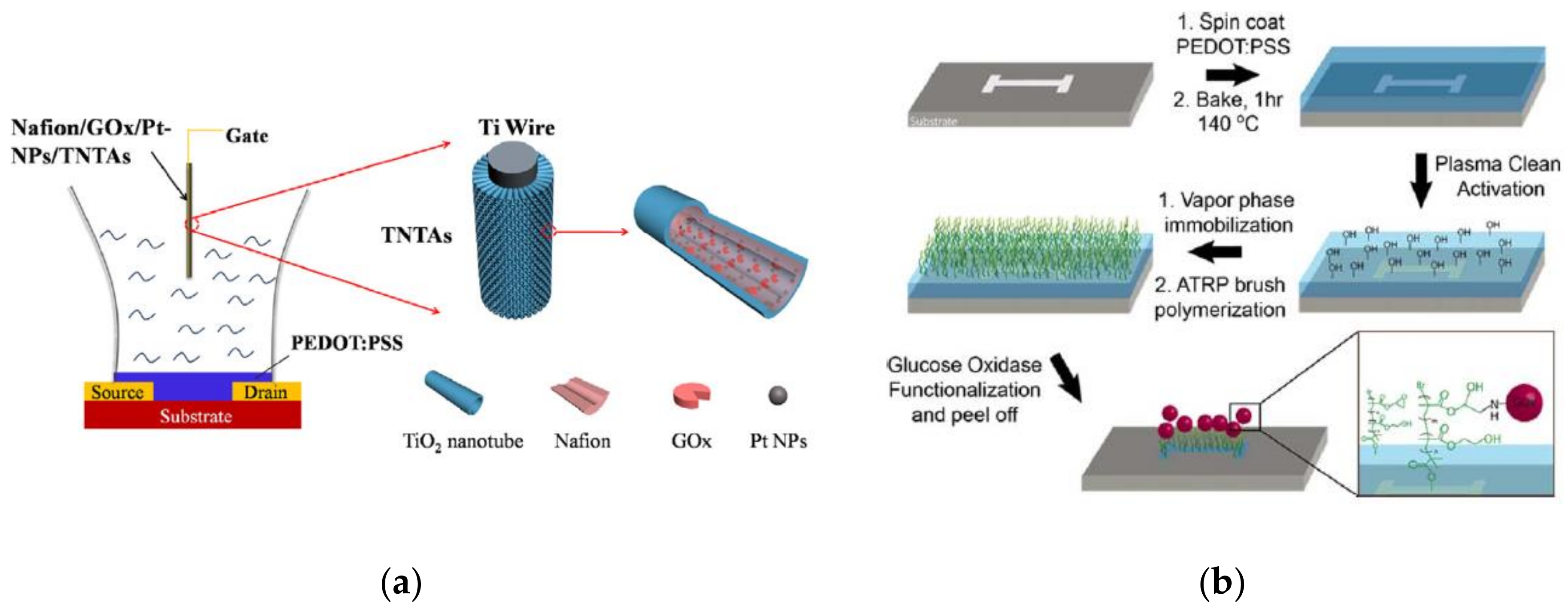
  90. Liao, J.; Lin, S.; Yang, Y.; Liu, K.; Du, W. Highly Selective and Sensitive Glucose Sensors Based on Organic Electrochemical Transistors Using TiO2 Nanotube Arrays-Based Gate Electrodes. Sens. Actuators B Chem. 2015, 208, 457–463. [Google Scholar] [CrossRef]
  91. Braendlein, M.; Pappa, A.-M.; Ferro, M.; Lopresti, A.; Acquaviva, C.; Mamessier, E.; Malliaras, G.G.; Owens, R.M. Lactate Detection in Tumor Cell Cultures Using Organic Transistor Circuits. Adv. Mater. 2017, 29, 1605744. [Google Scholar] [CrossRef] [PubMed]
  92. Macaya, D.J.; Nikolou, M.; Takamatsu, S.; Mabeck, J.T.; Owens, R.M.; Malliaras, G.G. Simple Glucose Sensors with Micromolar Sensitivity Based on Organic Electrochemical Transistors. Sens. Actuators B Chem. 2007, 123, 374–378. [Google Scholar] [CrossRef]
  93. Yang, S.Y.; Defranco, J.A.; Sylvester, Y.A.; Gobert, T.J.; Macaya, D.J.; Owens, R.M.; Malliaras, G.G. Integration of a Surface-Directed Microfluidic System with an Organic Electrochemical Transistor Array for Multi-Analyte Biosensors. Lab Chip 2009, 9, 704–708. [Google Scholar] [CrossRef] [PubMed]
  94. Yang, S.Y.; Cicoira, F.; Byrne, R.; Benito-Lopez, F.; Diamond, D.; Owens, R.M.; Malliaras, G.G. Electrochemical Transistors with Ionic Liquids for Enzymatic Sensing. Chem. Commun. 2010, 46, 7972–7974. [Google Scholar] [CrossRef] [PubMed] [Green Version]
  95. Kanakamedala, S.K.; Alshakhouri, H.T.; Agarwal, M.; DeCoster, M.A. A Simple Polymer Based Electrochemical Transistor for Micromolar Glucose Sensing. Sens. Actuators B Chem. 2011, 157, 92–97. [Google Scholar] [CrossRef]
  96. Tang, H.; Lin, P.; Chan, H.L.; Yan, F. Highly Sensitive Dopamine Biosensors Based on Organic Electrochemical Transistors. Biosens. Bioelectron. 2011, 26, 4559–4563. [Google Scholar] [CrossRef] [PubMed]
  97. Khodagholy, D.; Curto, V.F.; Fraser, K.J.; Gurfinkel, M.; Byrne, R.; Diamond, D.; Malliaras, G.G.; Benito-Lopez, F.; Owens, R.M. Organic Electrochemical Transistor Incorporating an Ionogel as a Solid-State Electrolyte for Lactate Sensing. J. Mater. Chem. 2012, 22, 4440–4443. [Google Scholar] [CrossRef] [Green Version]
  98. Tarabella, G.; Pezzella, A.; Romeo, A.; D’Angelo, P.; Coppedè, N.; Calicchio, M.; d’Ischia, M.; Mosca, R.; Iannotta, S. Irreversible Evolution of Eumelanin Redox States Detected by an Organic Electrochemical Transistor: En Route to Bioelectronics and Biosensing. J. Mater. Chem. B 2013, 1, 3843–3849. [Google Scholar] [CrossRef]
  99. Liao, C.; Mak, C.; Zhang, M.; Chan, H.L.; Yan, F. Flexible Organic Electrochemical Transistors for Highly Selective Enzyme Biosensors and Used for Saliva Testing. Adv. Mater. 2015, 27, 676–681. [Google Scholar] [CrossRef] [PubMed]
  100. Liao, C.; Zhang, M.; Niu, L.; Zheng, Z.; Yan, F. Organic Electrochemical Transistors with Graphene-Modified Gate Electrodes for Highly Sensitive and Selective Dopamine Sensors. J. Mater. Chem. B 2014, 2, 191–200. [Google Scholar] [CrossRef]
  101. Kergoat, L.; Piro, B.; Simon, D.T.; Pham, M.-C.; Noël, V.; Berggren, M. Detection of Glutamate and Acetylcholine with Organic Electrochemical Transistors Based on Conducting Polymer/Platinum Nanoparticle Composites. Adv. Mater. 2014, 26, 5658–5664. [Google Scholar] [CrossRef] [PubMed] [Green Version]
  102. Mak, C.H.; Liao, C.; Fu, Y.; Zhang, M.; Tang, C.Y.; Tsang, Y.H.; Chan, H.L.W.; Yan, F. Highly-Sensitive Epinephrine Sensors Based on Organic Electrochemical Transistors with Carbon Nanomaterial Modified Gate Electrodes. J. Mater. Chem. C 2015, 3, 6532–6538. [Google Scholar] [CrossRef]
  103. Gentile, F.; Ferrara, L.; Villani, M.; Bettelli, M.; Iannotta, S.; Zappettini, A.; Cesarelli, M.; Di Fabrizio, E.; Coppedè, N. Geometrical Patterning of Super-Hydrophobic Biosensing Transistors Enables Space and Time Resolved Analysis of Biological Mixtures. Sci. Rep. 2016, 6, 18992. [Google Scholar] [CrossRef] [PubMed] [Green Version]
  104. Coppedè, N.; Ferrara, L.; Bifulco, P.; Villani, M.; Iannotta, S.; Zappettini, A.; Cesarelli, M.; Di Fabrizio, E.; Gentile, F. Multiscale Modification of the Conductive PEDOT:PSS Polymer for the Analysis of Biological Mixtures in a Super-Hydrophobic Drop. Microelectron. Eng. 2016, 158, 80–84. [Google Scholar] [CrossRef]
  105. Gualandi, I.; Tonelli, D.; Mariani, F.; Scavetta, E.; Marzocchi, M.; Fraboni, B. Selective Detection of Dopamine with an All PEDOT:PSS Organic Electrochemical Transistor. Sci. Rep. 2016, 6, 35419. [Google Scholar] [CrossRef] [PubMed]
  106. Strakosas, X.; Huerta, M.; Donahue, M.J.; Hama, A.; Pappa, A.-M.; Ferro, M.; Ramuz, M.; Rivnay, J.; Owens, R.M. Catalytically Enhanced Organic Transistors for in Vitro Toxicology Monitoring through Hydrogel Entrapment of Enzymes. J. Appl. Polym. Sci. 2017, 134, 44483. [Google Scholar] [CrossRef]
  107. Guo, X.; Liu, J.; Liu, F.; She, F.; Zheng, Q.; Tang, H.; Ma, M.; Yao, S. Label-Free and Sensitive Sialic Acid Biosensor Based on Organic Electrochemical Transistors. Sens. Actuators B Chem. 2017, 240, 1075–1082. [Google Scholar] [CrossRef]
  108. Pecqueur, S.; Lenfant, S.; Guérin, D.; Alibart, F.; Vuillaume, D. Concentric-Electrode Organic Electrochemical Transistors: Case Study for Selective Hydrazine Sensing. Sensors 2017, 17, 570. [Google Scholar] [CrossRef] [PubMed]
  109. Xiong, C.; Wang, Y.; Qu, H.; Zhang, L.; Qiu, L.; Chen, W.; Yan, F.; Zheng, L. Highly Sensitive Detection of Gallic Acid Based on Organic Electrochemical Transistors with Poly(Diallyldimethylammonium Chloride) and Carbon Nanomaterials Nanocomposites Functionalized Gate Electrodes. Sens. Actuators B Chem. 2017, 246, 235–242. [Google Scholar] [CrossRef]
  110. Zhang, L.; Wang, G.; Wu, D.; Xiong, C.; Zheng, L.; Ding, Y.; Lu, H.; Zhang, G.; Qiu, L. Highly Selective and Sensitive Sensor Based on an Organic Electrochemical Transistor for the Detection of Ascorbic Acid. Biosens. Bioelectron. 2018, 100, 235–241. [Google Scholar] [CrossRef] [PubMed]
  111. Scheiblin, G.; Aliane, A.; Strakosas, X.; Curto, V.F.; Coppard, R.; Marchand, G.; Owens, R.M.; Mailley, P.; Malliaras, G.G. Screen-Printed Organic Electrochemical Transistors for Metabolite Sensing. MRS Commun. 2015, 5, 507–511. [Google Scholar] [CrossRef]
  112. Contat-Rodrigo, L.; Pérez-Fuster, C.; Lidón-Roger, J.V.; Bonfiglio, A.; García-Breijo, E. Screen-Printed Organic Electrochemical Transistors for the Detection of Ascorbic Acid in Food. Org. Electron. 2017, 45, 89–96. [Google Scholar] [CrossRef]
  113. Mattana, G.; Loi, A.; Woytasik, M.; Barbaro, M.; Noël, V.; Piro, B. Inkjet-Printing: A New Fabrication Technology for Organic Transistors. Adv. Mater. Technol. 2017, 2, 1700063. [Google Scholar] [CrossRef]
  114. Weng, B.; Morrin, A.; Shepherd, R.; Crowley, K.; Killard, A.J.; Innis, P.C.; Wallace, G.G. Wholly printed polypyrrole nanoparticle-based biosensors on flexible substrate. J. Mater. Chem. B 2014, 2, 793–799. [Google Scholar] [CrossRef]
  115. Yun, Y.H.; Lee, B.K.; Choi, J.S.; Kim, S.; Yoo, B.; Kim, Y.S.; Park, K.; Cho, Y.W. A Glucose Sensor Fabricated by Piezoelectric Inkjet Printing of Conducting Polymers and Bienzymes. Anal. Sci. 2011, 27, 375–379. [Google Scholar] [CrossRef] [PubMed]
  116. Faddoul, R.; Coppard, R.; Berthelot, T. Inkjet Printing of Organic Electrochemical Immunosensors. In Proceedings of the IEEE Sensors, Valencia, Spain, 2–5 November 2014; pp. 1088–1091. [Google Scholar]
  117. Sukeerthi, S.; Contractor, A.Q. Molecular Sensors and Sensor Arrays Based on Polyaniline Microtubules. Anal. Chem. 1999, 71, 2231–2236. [Google Scholar] [CrossRef] [PubMed]
  118. Kanungo, M.; Kumar, A.; Contractor, A.Q. Microtubule Sensors and Sensor Array Based on Polyaniline Synthesized in the Presence of Poly(Styrene Sulfonate). Anal. Chem. 2003, 75, 5673–5679. [Google Scholar] [CrossRef] [PubMed]
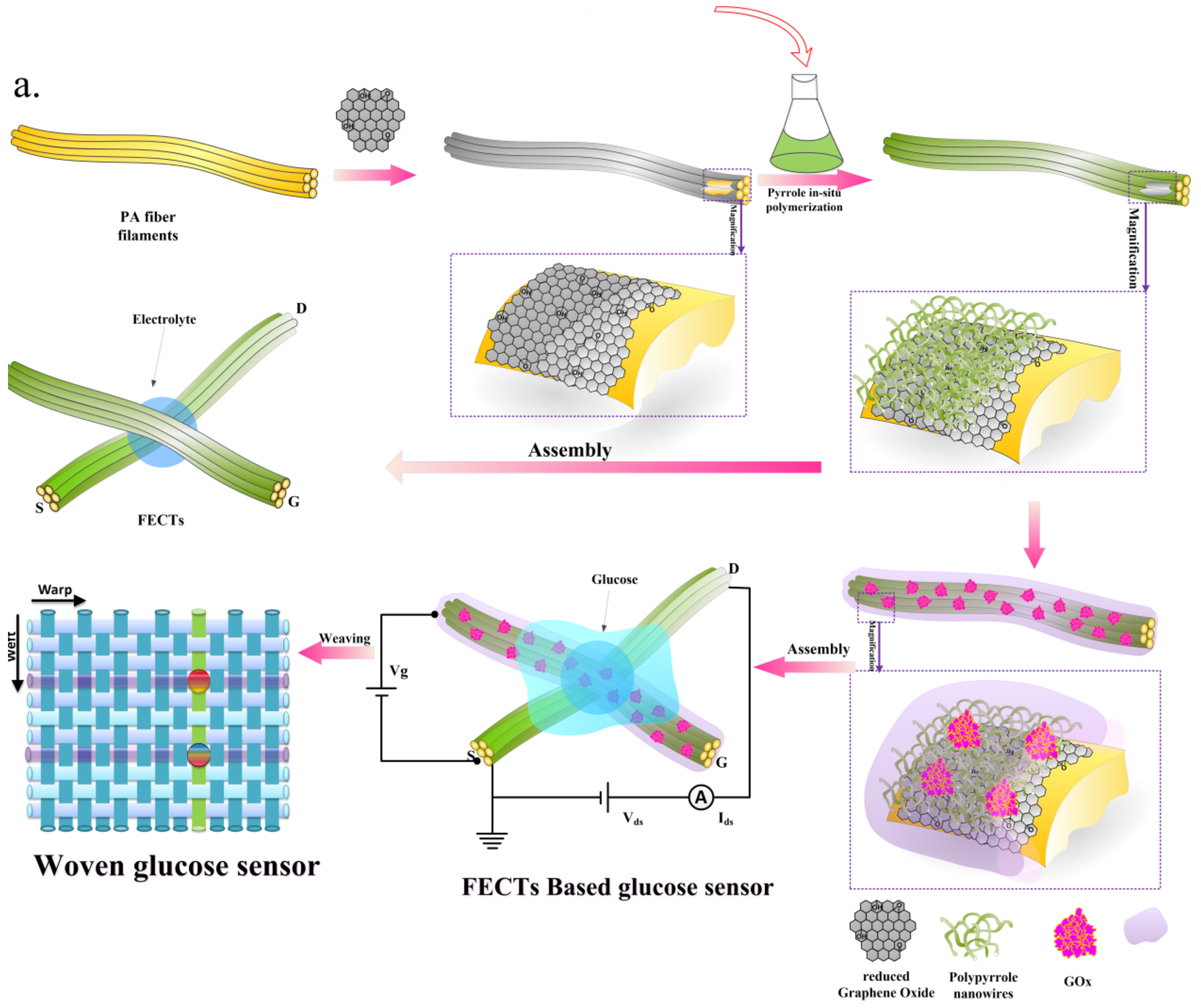
  119. Wang, Y.; Qing, X.; Zhou, Q.; Zhang, Y.; Liu, Q.; Liu, K.; Wang, W.; Li, M.; Lu, Z.; Chen, Y.; et al. The Woven Fiber Organic Electrochemical Transistors Based on Polypyrrole Nanowires/Reduced Graphene Oxide Composites for Glucose Sensing. Biosens Bioelectron. 2017, 95, 138–145. [Google Scholar] [CrossRef] [PubMed]
  120. Kim, Y.; Do, J.; Kim, J.; Yang, S.Y.; Malliaras, G.G.; Ober, C.K.; Kim, E. A Glucose Sensor Based on an Organic Electrochemical Transistor Structure Using a Vapor Polymerized Poly(3,4-Ethylenedioxythiophene) Layer. Jpn. J. Appl. Phys. 2010, 49, 01AE10. [Google Scholar] [CrossRef]
  121. Coppedè, N.; Tarabella, G.; Villani, M.; Calestani, D.; Iannotta, S.; Zappettini, A. Human Stress Monitoring through an Organic Cotton-Fiber Biosensor. J. Mater. Chem. B 2014, 2, 5620–5626. [Google Scholar] [CrossRef]
  122. Battista, E.; Lettera, V.; Villani, M.; Calestani, D.; Gentile, F.; Netti, P.A.; Iannotta, S.; Zappettini, A.; Coppedè, N. Enzymatic Sensing with Laccase-Functionalized Textile Organic Biosensors. Org. Electron. 2017, 40, 51–57. [Google Scholar] [CrossRef]
  123. Lin, P.; Yan, F. Organic Thin-Film Transistors for Chemical and Biological Sensing. Adv. Mater. 2012, 24, 34–51. [Google Scholar] [CrossRef] [PubMed]
  124. Hoa, D.T.; Kumar, T.N.S.; Punekar, N.S.; Srinivasa, R.S.; Lal, R.; Contractor, A.Q. A biosensor based on conducting polymers. Anal. Chem. 1992, 64, 2645–2646. [Google Scholar] [CrossRef]
  125. Bartlett, P.N.; Birkin, P.R. Enzyme switch responsive to glucose. Anal. Chem. 1993, 65, 1118–1119. [Google Scholar] [CrossRef]
  126. Wang, J.; Musameh, M.; Lin, Y.H. Solubilization of carbon nanotubes by Nafion toward the preparation of amperometric biosensors. J. Am. Chem. Soc. 2003, 125, 2408–2409. [Google Scholar] [CrossRef] [PubMed]
  127. Kang, Q.; Yang, L.; Cai, Q. An electro-catalytic biosensor fabricated with Pt-Au nanoparticle-decorated titania nanotube array. Bioelectrochemistry 2008, 74, 62–65. [Google Scholar] [CrossRef] [PubMed]
  128. Bai, J.; Zhou, B. Titanium Dioxide Nanomaterials for Sensor Applications. Chem. Rev. 2014, 114, 10131–10176. [Google Scholar] [CrossRef] [PubMed]
  129. Welch, M.E.; Doublet, T.; Bernard, C.; Malliaras, G.G.; Ober, C.K. A glucose sensor via stable immobilization of the GOx enzyme on an organic transistor using a polymer brush. J. Polym. Sci. A Polym. Chem. 2015, 53, 372–377. [Google Scholar] [CrossRef]
  130. Ji, X.; Chan, P.K.L. Biosensors and Biodetection: Methods and Protocols, Electrochemical, Bioelectronic, Piezoelectric, Cellular and Molecular Biosensors; Pickril, B., Rasooly, A., Eds.; Springer: Berlin/Heidelberg, Germany, 2017; Volume 2, pp. 205–216. ISBN 978-1-4939-6910-4. [Google Scholar]
  131. Adeva-Andany, M.; López-Ojén, M.; Funcasta-Calderón, R.; Ameneiros-Rodríguez, E.; Donapetry-García, C.; Vila-Altesor, M.; Rodríguez-Seijas, J. Comprehensive review on lactate metabolism in human health. Mitochondrion 2014, 17, 76–100. [Google Scholar] [CrossRef] [PubMed]
  132. Pappa, A.M.; Curto, V.F.; Braendlein, M.; Strakosas, X.; Donahue, M.J.; Fiocchi, M.; Malliaras, G.G.; Owens, R.M. Organic Transistor Arrays Integrated with Finger-Powered Microfluidics for Multianalyte Saliva Testing. Adv. Health Mater. 2016, 5, 2295–2302. [Google Scholar] [CrossRef] [PubMed]
  133. Ji, X.; Lau, H.Y.; Ren, X.; Peng, B.; Zhai, P.; Feng, S.-P.; Chan, P.K.L. Highly Sensitive Metabolite Biosensor Based on Organic Electrochemical Transistor Integrated with Microfluidic Channel and Poly(N-vinyl-2-pyrrolidone)-Capped Platinum Nanoparticles. Adv. Mater. Technol. 2016, 1, 1600042. [Google Scholar] [CrossRef]
  134. Erden, P.E.; Kilic, E. A review of enzymatic uric acid biosensors based on amperometric detection. Talanta 2013, 107, 312–323. [Google Scholar] [CrossRef] [PubMed]
  135. Banderet, L.E.; Lieberman, H.R. Treatment with tyrosine, a neurotransmitter precursor, reduces environmental stress in humans Brain. Res. Bull. 1989, 22, 759–762. [Google Scholar] [CrossRef]
  136. Solís, O.; García-Sanz, P.; Herranz, A.S.; Asensio, M.-J.; Moratalla, R. L-DOPA reverses the increased free amino acids tissue levels induced by dopamine depletion and rises GABA and tyrosine in the striatum. Neurotoxic. Res. 2016, 30, 67–75. [Google Scholar] [CrossRef] [PubMed]
  137. Wang, Y.; Xiong, C.; Qu, H.; Chen, W.; Ma, A.; Zheng, L. Highly sensitive real-time detection of tyrosine based on organic electrochemical transistors with poly-(diallyldimethylammonium chloride), gold nanoparticles and multi-walled carbon nanotubes. J. Electroanal. Chem. 2017, 799, 321–326. [Google Scholar] [CrossRef]
  138. Du, J.; Cullen, J.J.; Buettner, G.R. Ascorbic acid: Chemistry, biology and the treatment of cancer. Biochim. Biophys. Acta 2012, 1826, 443–457. [Google Scholar] [CrossRef] [PubMed] [Green Version]
  139. Pisoschi, A.M.; Pop, A.; Serban, A.I.; Fafaneata, C. Electrochemical methods for ascorbic acid determination. Electrochim. Acta 2014, 121, 443–460. [Google Scholar] [CrossRef]
  140. Wightman, R.M.; Jankowski, J.A.; Kennedy, R.T.; Kawagoe, K.T.; Schroeder, T.J.; Leszczyszyn, D.J.; Near, J.A.; Diliberto, E.J.; Viveros, O.H. Temporally resolved catecholamine spikes correspond to single vesicle release from individual chromaffin cells. Proc. Natl. Acad. Sci. USA 1991, 88, 10754–10758. [Google Scholar] [CrossRef] [PubMed]
  141. Tybrandt, K.; Kollipara, S.B.; Berggren, M. Organic electrochemical transistors for signal amplification in fast scan cyclic voltammetry. Sens. Actuators B Chem. 2014, 195, 651–656. [Google Scholar] [CrossRef] [Green Version]
  142. Michael, A.C.; Borland, L.M. Electrochemical Methods for Neuroscience; CRC Press: Boca Raton, FL, USA, 2007; ISBN 0-8493-4075-6. [Google Scholar]
  143. Wang, N.; Liu, Y.; Fu, Y.; Yan, F. AC Measurements Using Organic Electrochemical Transistors for Accurate Sensing. ACS Appl. Mater. Interfaces 2017. [Google Scholar] [CrossRef] [PubMed]
  144. Nilsson, D.; Berggren, M.; Svensson, J.P.-O. Electrochemical Sensor. Application WO2003046540A1, 5 June 2003. [Google Scholar]
  145. Kugler, T.; Berggren, M.; Remonen, T.; Malmström, A.I.; Knuthammar, B.; Norberg, P. Electrochemical Device. Grant US7482620B2, 27 January 2009. [Google Scholar]
  146. Ersman, P.A.; Nilsson, D.; Berggren, M.; Svensson, P.O.; Robinson, N.D. Electrochemical Device. Application US8810888B2, 23 May 2013. [Google Scholar]
  147. Yan, F.; Liao, C. Fiber-Based Organic Electrochemical Transistor. Application US9178170B2, 3 November 2015. [Google Scholar]
  148. Yan, F.; Chan, H.L.W.; Tang, H. Non-Invasive Glucose Sensor. Application US9632058B2, 4 October 2012. [Google Scholar]
  149. Seong, D.G.; Lee, K.E.; Um, M.K.; Lee, W.O.; Lee, J.U.; Jung, B.M.; Oh, Y.S. Organic Semiconductor Element, Fabrication Method Thereof, Woven and Non-Woven Fabric Structures Therewith, and Semiconductor Device Therewith. Application US9733209, 28 April 2016. [Google Scholar]
  150. Coppede, N.; Zappettini, A.; Marchini, L. Organic Electrochemical Sensor for Measuring Body Parameters. Application US20170027481A1, 2 February 2017. [Google Scholar]
  151. Ferro, M.; Malliaras, G. Organic Electrochemical Transistor. Application US9530976B2, 27 December 2016. [Google Scholar]
Figure 1. Qualitative OECT functioning mechanism. (a) Situation at zero gate voltage. Current flows through the device with respect to the intrinsic conductivity of the p-doped OSC. (b) Situation under application of a positive bias to the gate electrode. Cations penetrate in the OSC’s bulk and compensate the dopants’ negative charges resulting in the lowering of the polymer conductivity. Adapted from [30] and reproduced with permission from John Wiley and Sons, Copyright © 2007.
Applsci 08 00928 g001
Figure 2. Illustration of ascorbic acid oxidation at the gate electrode; PEDOT:PSS is, in turn, reduced leading to a drain current decrease. Reproduced from [57] with permission of The Royal Society of Chemistry.
Applsci 08 00928 g002
Figure 3. Commonly used conducting polymers: (a) Polypyrrole; (b) Polythiophene; (c) Poly(3,4-ethylenedioxythiophene); and (d) Polyaniline.
Applsci 08 00928 g003
Figure 4. Stabilization of the bipolaron in the PEDOT moiety by the presence of PSS co-polymer moiety.
Applsci 08 00928 g004
Figure 5. Difference between benzoid and quinoid forms (extended-coil structure) of PEDOT.
Applsci 08 00928 g005
Figure 6. Schematic illustration of the mechanism involved in the enhancement of PEDOT:PSS conductivity in presence of PEG. Reproduced from [78] with permission of The Royal Society of Chemistry.
Applsci 08 00928 g006
Figure 7. Diagram of the structural rearrangement of PEDOT:PSS. The amorphous PEDOT:PSS grains (left) are reformed into crystalline PEDOT:PSS nanofibrils (right) via a charge-separated transition mechanism (middle) via a concentrated H2SO4 treatment. Reproduced from [73] with permission from John Wiley and Sons, Copyright © 20013.
Applsci 08 00928 g007
Figure 8. Schematic illustration of the system of GOPS-crosslinked PEDOT:PSS. GOPS is only reacting with the parts of the PSS-chains (gray), not interacting with PEDOT (dark blue). The zoom in shows three main interactions involving GOPS; GOPS-PSS, GOPS-GOPS and GOPS-glass. (A) The chemical bonds between ASO3H group of PSS and the epoxy ring of GOPS, as well as the chemical bond between three GOPS molecules. (B) The chemical bond between hydroxyl groups at the glass surface and the methoxysilane groups of GOPS. Reproduced from [82] with permission from John Wiley and Sons, Copyright © 20017.
Applsci 08 00928 g008
Figure 9. Schematic of subtractive (a) and additive (b) photolithographic patterning approaches for organic films. The asterisks indicate the steps where the organic film would be damaged during conventional photolithography. The chemical structure of parylene-C is shown on the bottom. Reprinted from [87]. Copyright 2005, with permission from Elsevier.
Applsci 08 00928 g009
Figure 10. Screen-Printed Organic Electrochemical Transistors for metabolite sensing: (a) schematic representation of the OECT enzymatic sensor and the enzymatic reaction mechanism; and (b) photograph of the corresponding wafer with an OECT biosensor in inset. Reproduced with permission from [111]. © Materials Research Society 2015.
Applsci 08 00928 g010
Figure 11. Schematic diagram of glucose sensors based on fiber organic electrochemical transistors with active layer of PPy nanowires and rGO. Reprinted from [119]. Copyright 2017, with permission from Elsevier.
Applsci 08 00928 g011
Figure 12. (a) The schematic diagram of the device structure of PEDOT:PSS based OECTglucose sensor using Nafion/GOx/Pt-NPs/TNTAs as a gate electrode. Reprinted from [127]. Copyright 2014, with permission from Elsevier. (b) PGMA:PHEMA mixed polymer brush and GOx fabrication. Reproduced from [129] with permission from John Wiley and Sons, Copyright © 2015.
Applsci 08 00928 g012
Figure 13. Schematic diagram of an OECT with a UOx-GO/PANI/Nafi on-graphene/Pt gate Reproduced from [99] with permission from John Wiley and Sons, Copyright © 2014.
Applsci 08 00928 g013
Figure 14. Architecture of the OECT-based dopamine sensor, with electrolyte, gate ad PEDOT:PSS channel (left). Detail of the gate structure, with Nafion (or chitosan) and graphene (rGO) flakes immobilized on a Pt electrode. The electro-oxidation of dopamine occurs on the surface of the gate (right). Reproduced with permission from [100]. © Materials Research Society 2013.
Applsci 08 00928 g014
Figure 15. Schematic diagram of an OECT cross-section and the wiring system for device operation (right). Channel transconductance (gm) to additions of dopamine with different concentrations (left). Reprinted with permission from [143]. Copyright 2017 American Chemical Society.
Applsci 08 00928 g015
Figure 16. Schematic of the cotton-OECT device with a Pt gate and an adrenaline molecule in its sensing process (left). Plots of the normalized transistor response at different concentrations of adrenaline from 10−8 to 10−3 M, with a Pt-gate electrode at two different NaCl concentrations (10−1 and 10−2 M) (right). Reproduced from [121] with permission of The Royal Society of Chemistry.
Applsci 08 00928 g016
Figure 17. (a) The schematic diagram of an OECT-based GA sensor. D, S, and G represent the drain, source and gate electrode, respectively. The oxidation of gallic acid at the CNM-PDDA functionalized gate electrode (on the right). (b) Potential drop between the gate and channel of the OECT before (solid line) and after (dashed line) the addition of GA in PBS solution. Reprinted from [109]. Copyright 2017, with permission from Elsevier.
Applsci 08 00928 g017
Figure 18. Schemes demonstrating the principle for SA detection based on the OECTs using the PABA modified gate. Reprinted from [107]. Copyright 2016, with permission from Elsevier.
Applsci 08 00928 g018
Table 1. Most important characteristics of spin-coating fabrication processes.
Top-Down Approach
Spin Speed [rpm]Spin Duration [s]Post-Deposition TreatmentFinal Thickness [nm]Reference
[–][-]Thermal annealing in a vacuum oven at 150 °C for 30 min[-][89]
[-][-]Thermal annealing at 200 ° C for one hour in a glovebox filled with high purity N2~80[53]
3500[-]Thermal annealing at 200 ° C for one hour in a glovebox filled with high purity N2[-][54]
[-][-]Thermal annealing at 200 °C for one hour in a glovebox filled with high purity N280[90]
150030125 °C for one hour100[91]
Bottom-Up Approach
Spin Speed [rpm]Spin Duration [s]Post-Deposition TreatmentFinal Thickness [nm]Reference
1500[-]Immersion in deionized water to remove any excess of DBSA100[92]
1500[-]Thermal annealing on a hotplate for 20 s at 140 °C followed by a second annealing under vacuum at 140 °C for 1 h. Subsequent soaking in deionized water to remove any surface contamination[-][52]
1500[-]Thermal annealing at 140 °C under vacuum for 1 hour followed by immersion in deionized water to remove any excess DBSA100[53]
[-][-]Prebaking at 90 °C for 150 seconds followed by thermal annealing under vacuum at 130 °C for 1 h100[93]
[-][-]Thermal annealing at 140 °C on a hotplate for 1 h[-][94]
100045Thermal annealing at 150 °C in air200[95]
3500[-]Thermal annealing at 200 °C for 60 min in a glove box filled with high purity N2 gas80[96]
[-][-]Thermal annealing at 140 °C for 60 min200[97]
150030Thermal annealing at 120 °C for 75 min~80[98]
[-][-]Thermal annealing at 120 °C for 60 min~80[34]
[-][-]Thermal annealing at 120 °C for 60 min in a glove box filled with high purity N2 gas~80[99]
3500[-]Thermal annealing at 200 °C for 60 min in a glove box filled with high purity N2 gas[-][100]
[-][-]Thermal annealing at 140 °C for 60 min followed by soaking in deionized water for 60 min to remove the loosely bound polymer chains[-][101]
300010Pre-baking at 60 °C for 5 min then thermal annealing at 140 °C for 30 min, after removing the insulating tape[-][57]
[-][-]Thermal annealing at 140 °C in air460[102]
[-][-]Thermal annealing at 140 °C for 60 min~80[103]
[-][-]Thermal annealing at 140 °C for 60 min[-][104]
5003[-][-][105]
3000[-]Pre-baking at 100 °C for 90 s, followed by immersion in deionized water and thermal annealing 140 °C for 30 min[-][106]
[-][-]Thermal annealing at 130 °C for 10 min followed by another baking at 150 °C for 1 h under high purity N2[-][107]
[-][-]Thermal annealing at 140 °C for 60 min[-][108]
600 + 30009 + 30Thermal annealing at 185 °C for 60 min[-][109]
[-][-]Thermal annealing at 185 °C for 60 min under N2~60[110]
Table 2. Properties of available commercial PEDOT:PSS inks.
PEDOT:PSS SourceConductivity
(S/cm)
Surface Resistance
(Ω/sq)
PEDOT/PSS Ratio
(by Weight)
Solids Content
(%)
References
Baytron P AI 40830.001-1:61.3 to 1.7[66,70,72,74]
Brayton P (Clevios P)1-1:2.51.3[52,55,80,89,92,95]
Clevios PH5005-1:2.51.2[34,90,94,97,98,103,104,121]
Ckevios PH100010-1:2.51.2[57,73,76,77,78,79,82,83,91,105,107,108,109]
Clevios P Jet NV2200--0.6 to 1.2[101]
Orgacon EL-P 3040-680-3.4[93]
Orgacon IJ1005-110-0.8[116]
Gwent C2100629D1----[112]
Not applicable *----[53,54,67,71,75,81,84,85,86,96,99,100,102,110,113,114,115,116,118,119,120]
* Not specified or not sufficiently described.

