Article

Diode Laser Welding/Brazing of Aluminum Alloy to Steel Using a Nickel Coating

1
School of Materials Engineering, Shanghai University of Engineering Science, Shanghai 201620, China
2
Shanghai Collaborative Innovation Center of Laser Advanced Manufacturing Technology, Shanghai 201620, China
3
Key Laboratory of Robot and Welding Automation of Jiangxi Province, School of Mechanical and Electrical Engineering, Nanchang University, Nanchang 330031, China
4
School of Mechanical, Electronic, and Industrial Engineering, University of Electronic Science and Technology of China, Chengdu 611731, China
5
Center for Advanced Materials Joining, University of Waterloo, Waterloo, ON N2L 3G1, Canada
*
Authors to whom correspondence should be addressed.
Appl. Sci. 2018, 8(6), 922; https://doi.org/10.3390/app8060922
Submission received: 18 May 2018 / Revised: 29 May 2018 / Accepted: 30 May 2018 / Published: 4 June 2018
(This article belongs to the Special Issue Selected Papers from the NMJ2018)

Abstract

:
Joining Al alloy to steel is of great interest for application in the automotive industry. Although a vast number of studies have been conducted to join Al to steel, the joining of Al to steel is still challenging due to the formation of brittle Fe–Al intermetallic compounds. In this work, the microstructure and mechanical properties of the dissimilar Al/steel joints with and without a nickel coating are comparatively investigated. A homogenous reaction layer composed of FeZn10 and Fe2Al5 is formed at the interface in the joints without Ni coating, and the joint facture load is only 743 N. To prevent the formation of brittle Fe2Al5, Ni electroplated coating is applied onto a steel surface. It has been shown that a nonhomogeneous reaction layer is observed at the interfacial region: Ni5Zn21 is formed at the direct irradiation zone, while Al3Ni is formed at the fusion zone root. The microhardness of the interfacial layer is reduced, which leads to the improvement of the joint mechanical properties. The average fracture load of the Al/Ni-coated steel joints reaches 930 N. In all of the cases, failure occurs at the Ni coating/fusion zone interface.

1. Introduction

The joining of dissimilar materials offers the potential to utilize the advantages of different materials, often providing a whole structure with unique mechanical properties. Aluminum alloys can reduce the weight of structural parts due to its light weight, and steel has a high strength. Hybrid structures of aluminum alloy and steel are suggested in automotive applications to improve the fuel efficiency and control air pollution through reducing the weight [1,2,3].
The joining of aluminum alloys to steel is a great challenge due to the large differences in the thermophysical properties between these two materials, and especially the formation of inherently hard and brittle Fe–Al intermetallic compounds (IMCs) at elevated temperatures, such as FeAl, FeAl2, FeAl3, and Fe2Al5. Early attempts at fusion welding of steel to aluminum alloys suffered from joint brittleness at the dissimilar interface caused by extensive IMC formation. More recently, many advanced welding technologies have been applied in Al/steel joining, such as friction stir welding [4], ultrasonic welding [5], explosive welding [6], laser keyhole welding [7], as well as arc, laser, and laser-hybrid welding/brazing [8,9,10,11,12]. The welding/brazing offers a great potential for Al/steel joining, owing to the advantage in reducing residual stress and controlling the IMCs. In the welding/brazing of Al to steel, the workpieces and filler metal are heated or melted by a heat source, and the joint has dual-characteristics, i.e., it has a fusion-welded joint at the Al side, and a brazed joint at the steel side. Some related investigations have claimed the observation of Fe–Al IMCs in Al/steel joints by welding/brazing [9,10,11].
The use of materials (interlayer, filler metal, coating, or their combinations) that becomes part of the joint has proven to be sufficient to inhibit the formation of brittle IMCs in dissimilar materials welding/brazing, such as Mg/Ti [13], Al/Mg [14,15], and NiTi/Ti6Al4V [16]. For example, in the investigation of laser joining of NiTi to Ti6Al4V, Oliveira et al. [16] successfully inhibited the formation of brittle Ni–Ti IMCs by inserting a niobium interlayer. The common features of the materials can be summarized as: (1) a higher melting point than parent metals, so that the alloy mixing of parent materials can be deterred; (2) excellent metallurgical capability with parent metals; (3) no brittle or much less brittle reaction products are formed with either parent material. With these criteria in mind, Ni is considered as a promising candidate for the dissimilar Al/steel joining, because of its good miscibility with Fe and sound metallurgical capability with Al. Although its melting point is 83 °C lower than Fe, the inhibition of alloy mixing by Ni still can be accomplished by using accurately tailored energy distribution during welding. In fact, Chen et al. [17,18] made attempts to join Al to steel with a Ni interlayer. However, brittle Fe–Al IMCs were still formed by the direct mixing of Fe and Al, owing to completely melting the Ni interlayer by Nd:YAG laser penetration welding technology.
In the present study, a diode laser with a more uniform energy distribution is applied. Compared to the keyhole mode in the Nd:YAG laser penetration welding, a conduction mode is figureachieved, which eases the accurate control of energy distribution and thus enables the welding/brazing technology. Ni, in the form of electroplated coating on steel, is used in a lap joint configuration. To highlight the effect of Ni coating, the microstructure and mechanical properties of laser Al/Ni-coated steel joint is drawn as a comparison with that of the laser Al/bare steel joint.

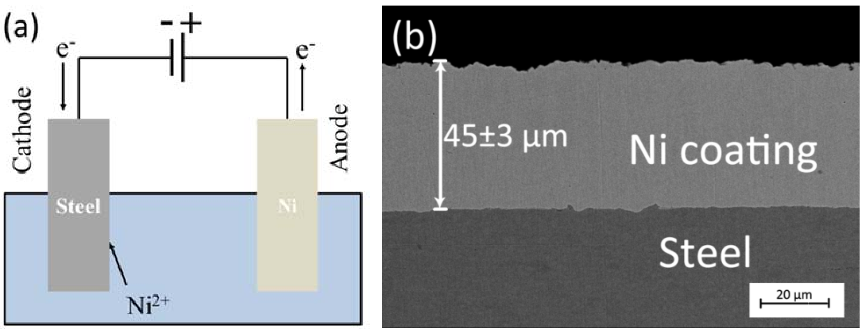
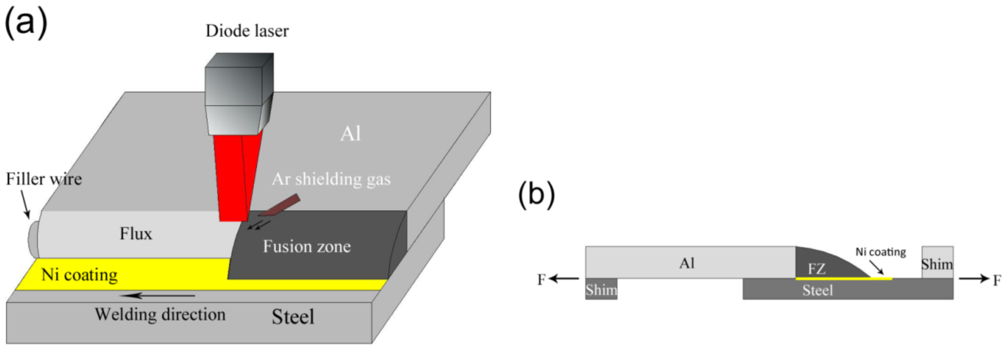
2. Experimental Procedure

In this study, 1.5-mm thick 5754 aluminum alloy and DP980 steel sheets were used as the base materials. Their chemical compositions and mechanical properties are given in Table 1 and Table 2. A 1.6-mm diameter Zn-based filler metal (Zn-22Al) filler metal with solidus and liquidus temperatures of 441 °C and 482 °C was used. An anticorrosive brazing flux Superior No. 20 was used.
Base materials were machined as rectangular strips of 50 × 60 mm2. The aluminum alloy sheets went through a very strict two-step cleaning process, which was shown in our previous study [19]. The steel sheets were cleaned in acetone, and then ground to 1000 grit using SiC abrasive paper and again ultrasonically cleaned in acetone. The prepared surfaces were then immediately electroplated with electrolytic pure Ni. In the Ni electroplating process, the clean steel sample was the cathode, and the pure Ni sheet was the anode. The composition of the electroplating solution and the electroplating conditions are listed in Table 3. Figure 1a shows a schematic of the Ni electrodeposition process. To get a uniform 45-μm thick Ni layer on the steel, different cathode current densities and plating times were tested. The electrodeposition of Ni using a cathode current density of 300 mA/cm2 for 20 min was found to provide a 45 ± 3-μm-thick pure Ni coating layer on the steel with a defect-free interface. Figure 1b shows the SEM images of Ni-coated steel. Energy-dispersive X-ray spectrometer (EDS) analysis of the electrodeposited layer on the steel showed a pure Ni coating.
An integrated Panasonic six-axis robot and a 4-kW Nuvonyx diode laser system were used for laser welding/brazing. A 1 × 12 mm2 rectangular laser beam intensity profile was obtained at the focal point. The filler metal was placed on the surface of the steel sheet. Shielding gas (99.99% Ar) was applied with a flow rate of 15 L/min to limit oxidation. The experimental setup of the laser welding/brazing is shown in Figure 2a. Before the experiment, preliminary trials were conducted to obtain a visually acceptable joint. The process parameters are listed in Table 4.
After welding, tensile test specimens with the dimensions of 5 × 90 mm2 were cut from the assemblies by the abrasive water jet technique. The specimens were evaluated by tensile-shear tests at room temperature with a crosshead speed of 1 mm/min. Shims were clamped to each end of the specimens to keep the joint interface parallel to the loading direction, as shown in Figure 2b. The joint strength was presented as a fracture load with the unit of newton (N), as the geometries of the tensile samples were not identical, because of various fusion zone (FZ) geometries and complex stresses. The microhardness testing was carried out with a 100-g load force and 15-s dwell time.
The specimens were cut across the joints to obtain cross-sections to study the macrostructure and microstructure. The specimens were then mechanically ground using 400, 600, 800, 1000, and 1200 grades of SiC papers followed by polishing with a 1-μm diamond suspension. Keller’s reagent was used to reveal the microstructure of the sectioned joints. They were then observed using an Olympus BX51M optical microscope (OM). The microstructure and fracture morphology were analyzed using a JEOL JSM 6460 scanning electron microscope (SEM). The composition was determined using Oxford INCA energy-dispersive X-ray spectrometer (EDS). The phase constitution of fractured joints was analyzed by X-ray diffraction (XRD) using a diffractometer with Cu Ka1 radiation.

3. Results

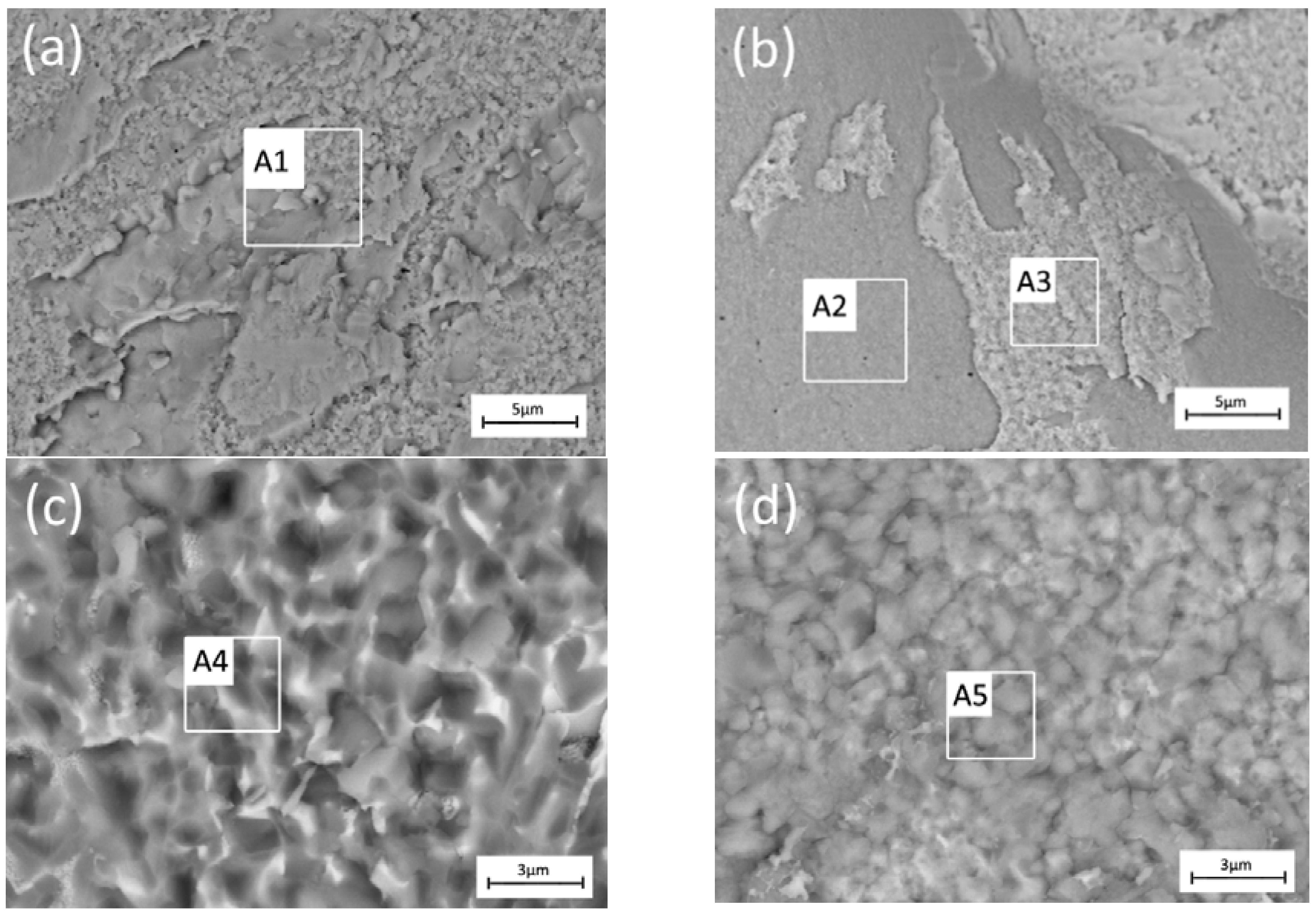
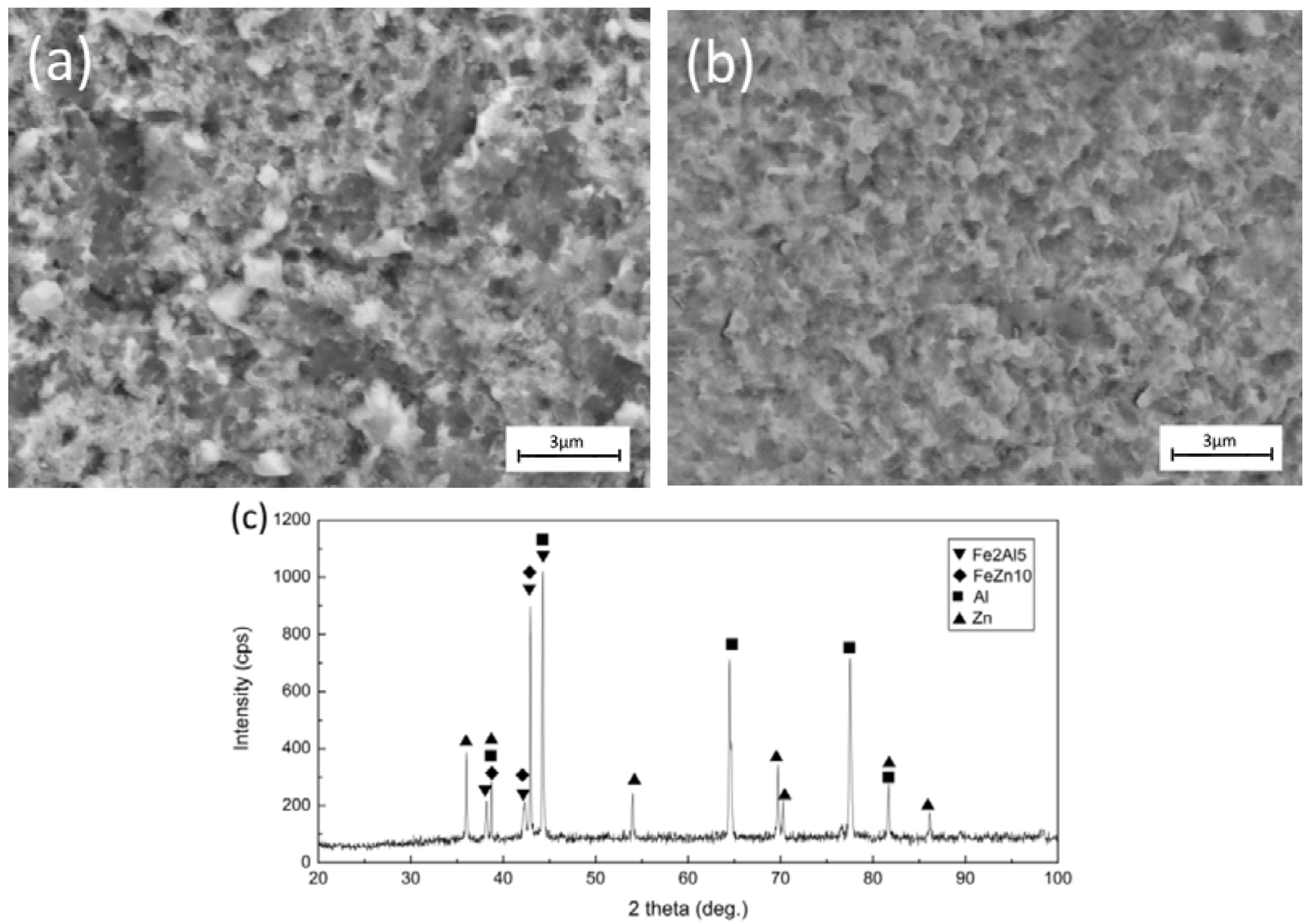
3.1. Microstructures

The top surface appearance and typical cross-section of the laser Al/Ni-coated steel joint are presented in Figure 3. With a 3-mm defocusing amount above the filler metal, a uniform FZ with good wetting (wetting angle 53.5°) on Ni coating substrate was observed. As marked in Figure 3b, the FZ/Ni coating interface was mainly divided into two zones: direct irradiation zone and the FZ root. The microstructure was observed to vary from the direct irradiation zone to the FZ root. The local heating characteristics of the temperature gradient along the interface were considered as the main reason for the evident variation of microstructure along the FZ/Ni interface [20,21].
Figure 4 displays the backscattered electron image (BEI) of the interfacial area in the Al/Ni-coated steel joint. The Ni coating was clearly observed at the interface, indicating that only part of the Ni coating was dissolved into the FZ during laser irradiation. A nonhomogeneous reaction layer was formed at the interface. In the direct irradiation zone, a wavy light layer with a thickness of 3.5 μm was observed (Figure 4a,c). To analyze this reaction layer, EDS point analysis was performed at point 1. According to Al-Ni-Zn ternary phase diagram [22,23], the possible phase of the reaction layer was Ni5Zn21, since it consisted of 6.1 ± 0.7 at.% Al, 74.4 ± 0.3 at.% Zn, and 19.4 ± 0.5 at.% Ni (Table 5). This phase was then confirmed by XRD, which will be shown later. Between Ni5Zn21 and FZ, a large number of dark particles was obvious. The EDS results shows that they had the average chemical composition of 68.9 ± 0.9 at.% Al, 3.5 ± 0.3 at.% Zn, and 27.6 ± 0.4 at.% Ni, which corresponded to the possible phase of Al3Ni. In the FZ root, a 1.5-μm thick uniform dark layer was formed at the FZ/Ni interface (Figure 4b,d). Base on EDS analysis, it had the average composition of 69.5 ± 5.1 at.% Al, 7.2 ± 0.9 at.% Zn, and 23.2 ± 4.5 at.% Ni, which was identified as Al3Ni.
Figure 5 shows the BEI of the interfacial region in the Al/bare steel joint. In the direct irradiation zone, two phases were seen in an 8-μm thick reaction layer. Based on EDS analysis, the average chemical composition of the dark matrix was 71.6 ± 0.5 at.% Al, 23.8 ± 0.1 at.% Fe, and 4.6 ± 0.5 at.% Zn, while the light granular phase had an average composition of 10.8 ± 3.6 at.% Al, 9.7 ± 1.8 at.% Fe, and 79.5 ± 3.1 at.% Zn. According to the Al–Fe–Zn phase diagram and related studies [23], the possible phases were Fe2Al5 and FeZn10 (Table 5). In the FZ root, the same phase components, i.e., Fe2Al5 and FeZn10, were formed at the reaction layer; however, the layer thickness decreased to around 4 μm. It suggested that the temperature variation along the interface of the laser Al/steel joint would not lead to the change in phase component, but rather only decrease the thickness of the interfacial layer. Thus, a homogeneous reaction layer was formed in the Al/bare steel joint.

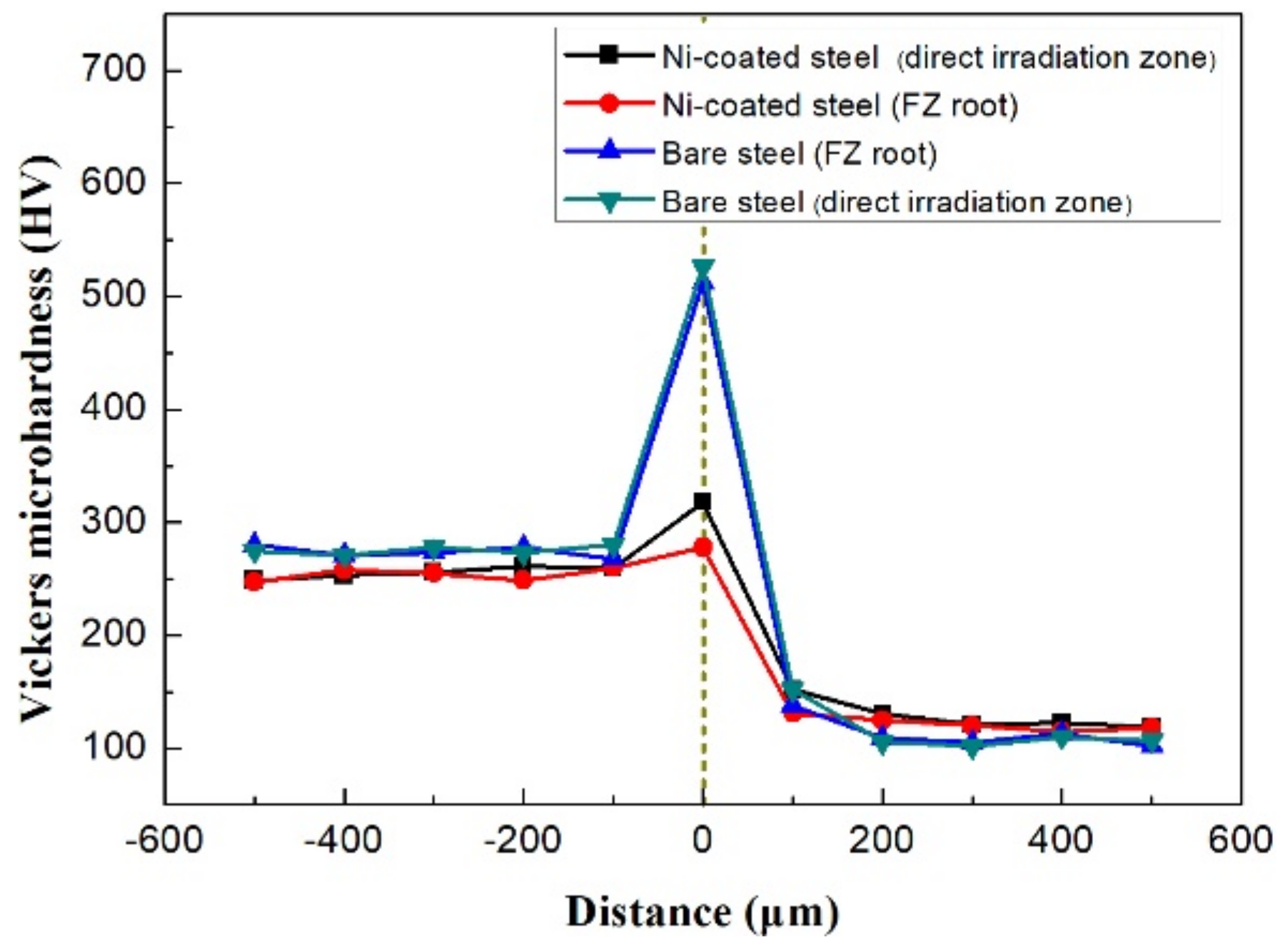
3.2. Mechanical Properties

Figure 6 shows the microhardness profile of the interfacial region in the Al/Ni-coated steel joint and Al/bare steel joint. At least three measurements were conducted to obtain relatively accurate hardness results. For the Al/Ni-coated steel joint, the average microhardness of the interfacial layer at the direct irradiation zone was 318 HV, which was harder than FZ (~120 HV) and the Ni coating (~255 HV). With regard to the FZ root, the average microhardness of the interfacial layer was 278 HV. For the Al/bare steel joint, a similar microhardness of the interfacial layer was obtained at the direct irradiation zone and the FZ root, which ranged from 512 to 526 HV. It was apparently much harder than that of the Al/Ni-coated steel joint. It was reported that Fe2Al5 was the hardest phase among all of the Fe-Al IMCs, which was responsible for the higher microhardness in the Al/bare steel joint. Besides, it was well established that a higher microhardness indicated a more brittle microstructure [8,9]. That was to say, the interfacial reaction layer with the Al/Ni-coated steel joint could be much less brittle than that of the Al/bare steel joint.
Tensile-shear testing results showed that the fracture load of the laser Al/Ni-coated steel joint reached 932 ± 92 N, while the fracture load of the laser Al/bare steel joint was only 743 ± 65 N. It was concluded that the joint fracture load increased by about 26% after inserting the Ni coating. The improvement on the fracture load will be discussed later.

3.3. Fractography

All of the tensile specimens were fractured at the FZ/Ni coating interface in Al/Ni-coated steel joints. Figure 7 shows the SEM images and XRD pattern of the fracture surfaces for the laser Al/Ni-coated steel joint at different zones. Various fracture surface morphologies were observed at the direct irradiation zone. On the FZ side (Figure 7a), some tearing ridges were clearly observed that had the average chemical composition of 2.9 ± 0.4 at.% Al, 74.0 ± 2.7 at.% Zn, and 23.1 ± 3.0 at.% Ni (Table 6). It was confirmed as Ni5Zn21. Whereas, on the steel side (Figure 7b), fracture morphologies with different characteristics were observed, including a very smooth feature and some scattering rugged features on the top. The average chemical composition of 100 at.% Ni was found at the smooth feature, while the scattering rugged feature contained 4.3 ± 0.5 at.% Al, 72.2 ± 1.8 at.% Zn, and 21.9 ± 1.6 at.% Ni (Table 6). Thus, it suggested that a mixed fracture consisting of shear brittle fracture at the Ni5Zn21/Ni interface and cleavage brittle fracture in the Ni5Zn21 layer occurred. At the FZ root, the characteristics of intergranular debonding were evident (Figure 7c,d). Based on EDS analysis, the FZ side and steel side had the respective chemical composition of 64.5 ± 2.5 at.% Al, 8.5 ± 3.3 at.% Zn, 27.0 ± 1.3 at.% Ni, and 66.1 ± 2.3 at.% Al, 10.0 ± 3.1 at.% Zn, and 23.9 ± 2.2 at.% Ni (Table 6). Hence, they could be identified as Al3Ni. Thus, it inferred that the intergranular debonding occurred in Al3Ni layer. Figure 7e shows the XRD patterns of the fracture surface. Diffraction peaks of Ni5Zn21 and Al3Ni were detected on the FZ side, which confirmed the SEM and EDS results.
In terms of the laser Al/bare steel joint, tearing ridges embedded with some light particles were evident in Figure 8a,b. Similar chemical composition was found at both fracture surfaces, which was 53.1 ± 2.8 at.% Al, 31.9 ± 3.1 at.% Fe, and 15.0 ± 1.3 at.% Zn. They were identified as Fe2Al5 and FeZn10. It suggested that the failure could occur at this reaction layer (Figure 5). Figure 8c shows the XRD patterns of the fracture surface. Diffraction peaks of Fe2Al5 and FeZn10 were obviously observed, corresponding to the SEM and EDS analysis. Besides, peaks of FeZn10 were mainly low diffraction peaks, suggesting that these IMCs in the form of particles existed adjacent to the interface.

4. Discussion

The above results of the microstructure and mechanical properties analysis indicated that the presence of Ni coating leads to the change of interfacial reaction products from Fe2Al5 and FeZn10 to Ni5Zn21 and Al3Ni, which resulted in the improvement of joint mechanical properties. Thus, Ni coating has a significant effect on the joint strength enhancement, which will be discussed further below.
With the tailored energy distribution, the complete melting of Ni coating was avoided. Thus, the element mixing between Al and Fe could be thoroughly prohibited as the present of this physical barrier. Consequently, the formation of brittle Fe2Al5 was deterred. Instead, less brittle Ni5Zn21 and Al3Ni were formed at the interface. Less brittle reaction products had higher resistance to crack initiation and propagation during tensile loading. Thus, the joint strength was improved.
Based on the analyses above, the joining mechanism of Al to Ni-coated steel was clarified with the aid of the schematic shown in Figure 9.
Firstly, with the application of laser irradiation, melting of the filler metal occurred upon heating to the melting point of the filler metal (~482 °C). Then, the liquid filler metal wetted the Ni substrate and intimately contacted each other (Figure 9a). When the temperature approached the melting point of the Al base metal, parts of the Al base metal started to melt, and then mixed with molten filler metal, forming the FZ. As the Gaussian distribution of the laser beam, it would result in a non-uniform thermal distribution at this region. It in turn led to various metallurgical reaction products at the interface. At the direct irradiation zone, the temperature would be higher, which resulted in the excessive dissolution of Ni and intense elemental diffusion (Figure 9b). Consequently, the L + Ni→Ni5Zn21 transformation happened at 881 °C [24] (Figure 9c). While, at the FZ root, the lower temperature along with the limited dissolution of Ni and elemental diffusion was obtained, which only allowed the formation of Al3Ni through the transformation of L + Ni→Al3Ni at 640 °C [25] (Figure 9d). A similar phase transformation occurred adjacent to Ni5Zn21 at the direct irradiation zone by a metallurgical reaction between dissolved Ni and FZ metal.

5. Conclusions

Laser welding/brazing of Al alloy to Ni-coated steel by characterization of a microstructure, hardness distribution, and joint fracture load was performed. The influence of Ni coating was clarified by comparing the Al/bare steel joints. The following conclusions were made:
(1)
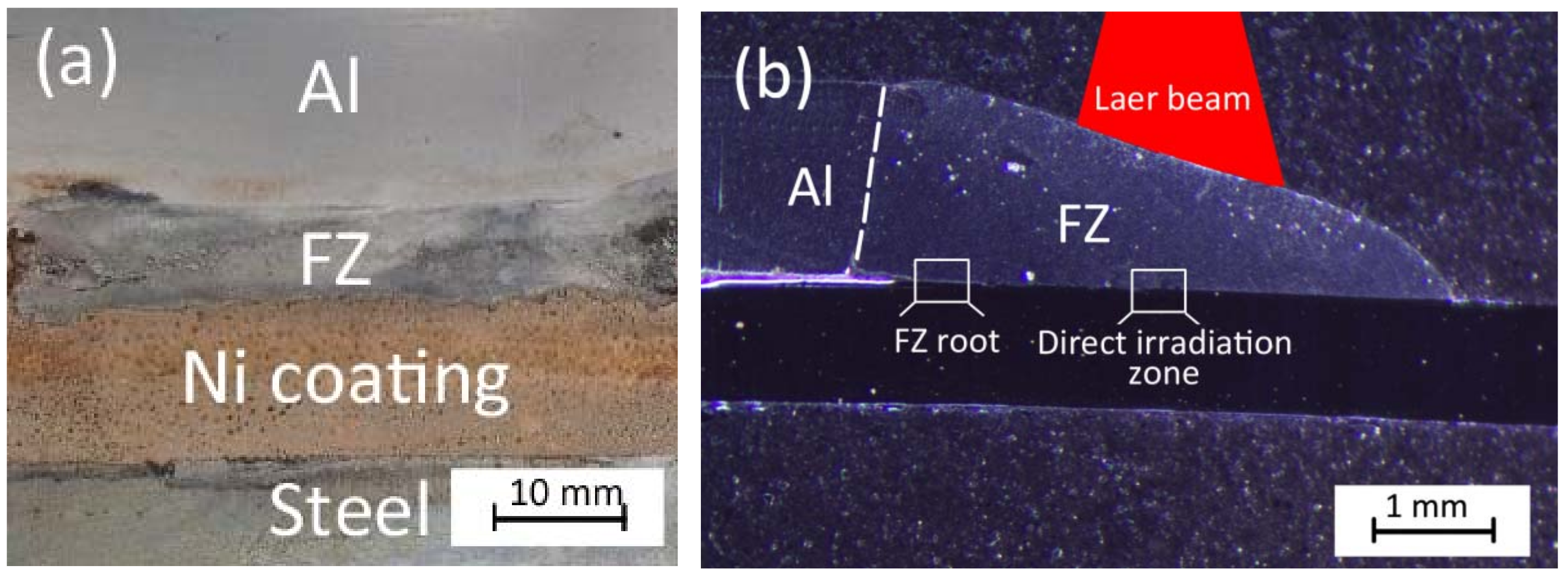
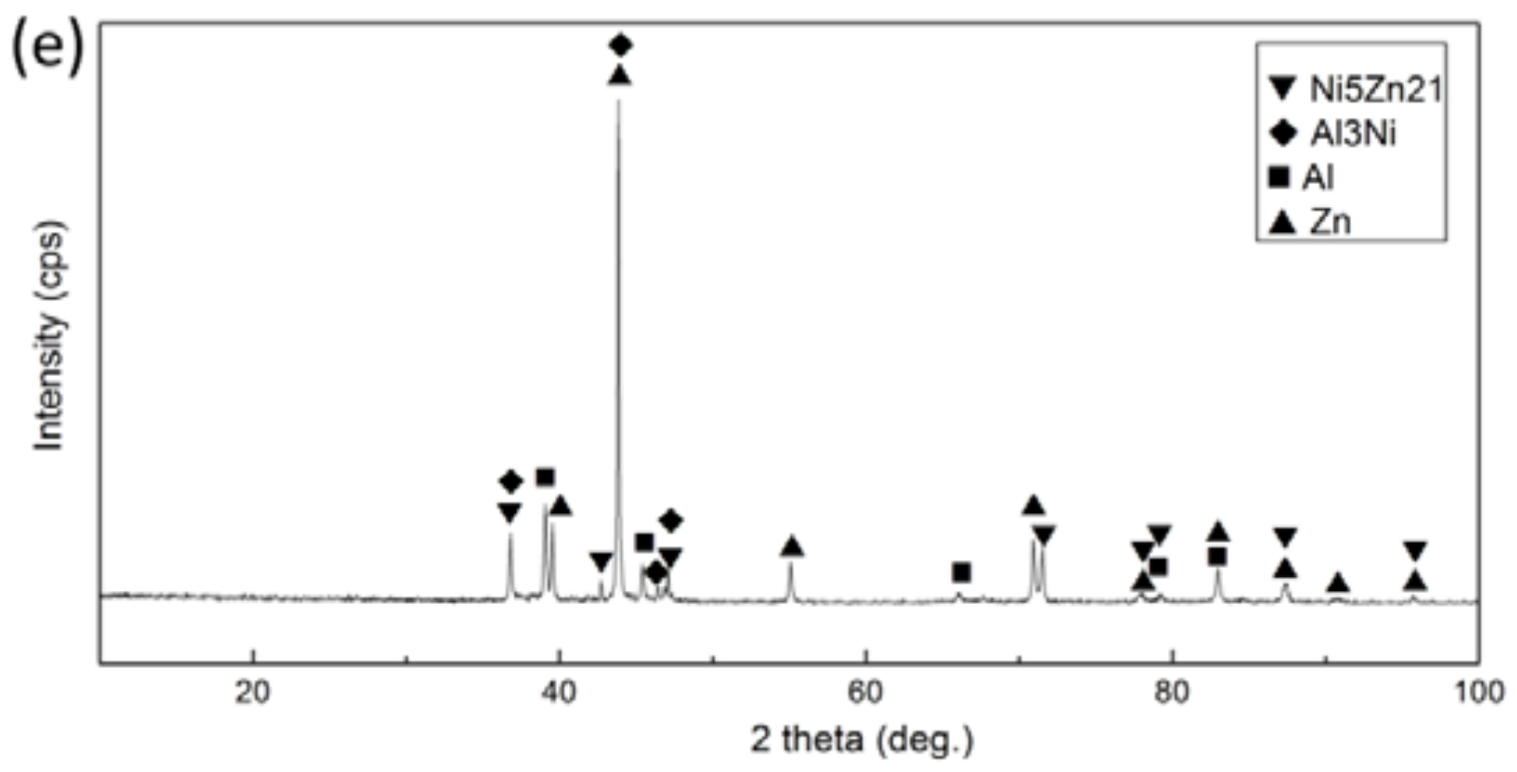
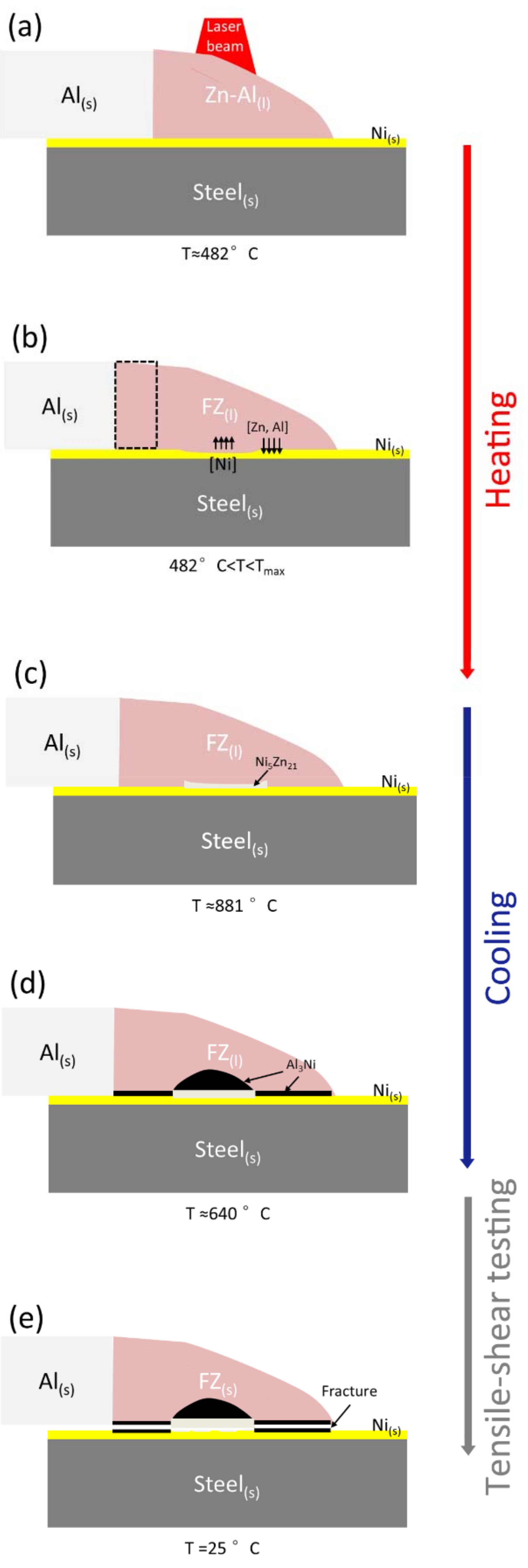
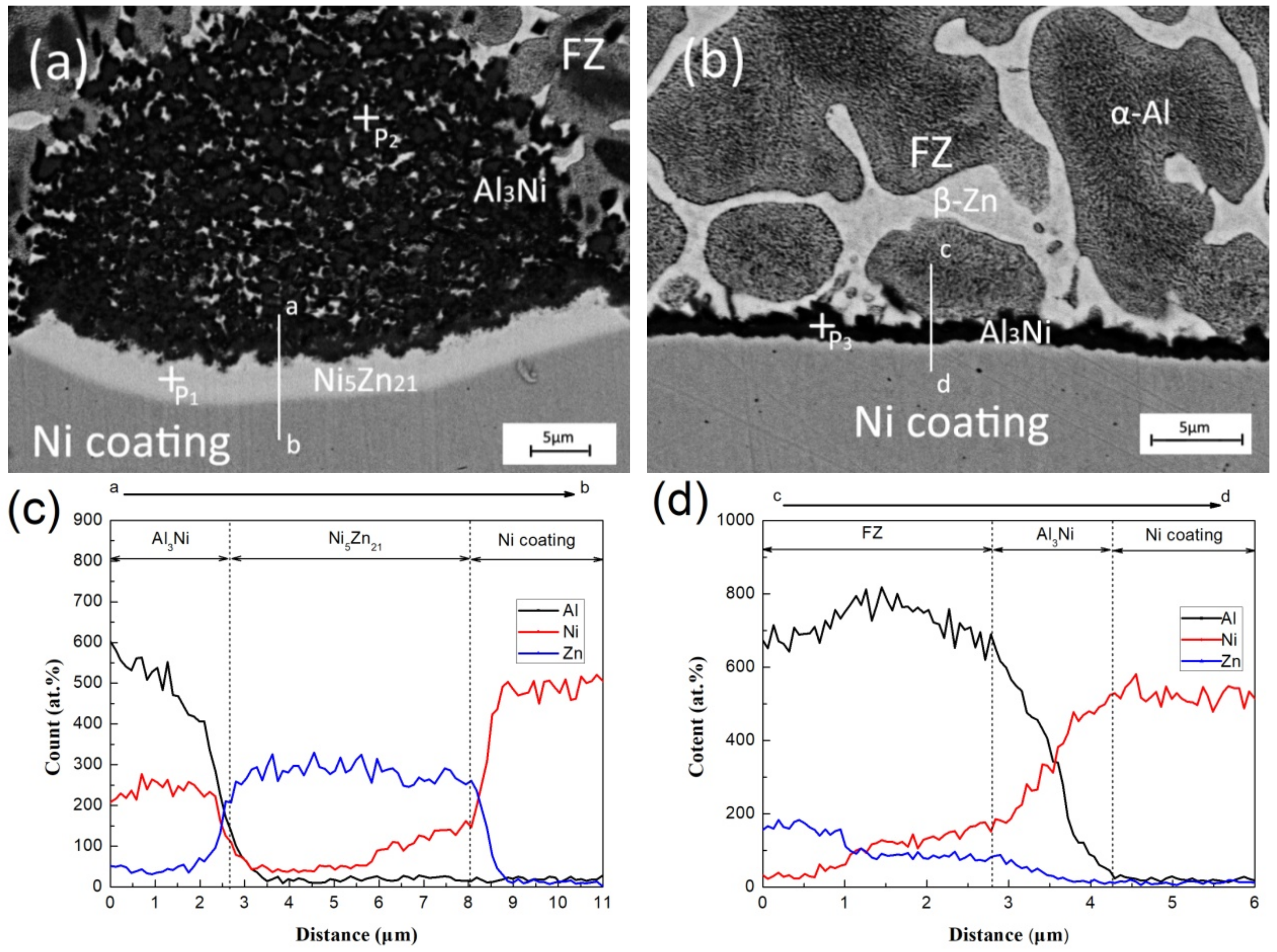
For the Al/Ni-coated steel joint, a nonhomogeneous reaction layer was observed at the interface: Ni5Zn21 formed at the direct irradiation zone, while Al3Ni formed at the FZ root.
(2)
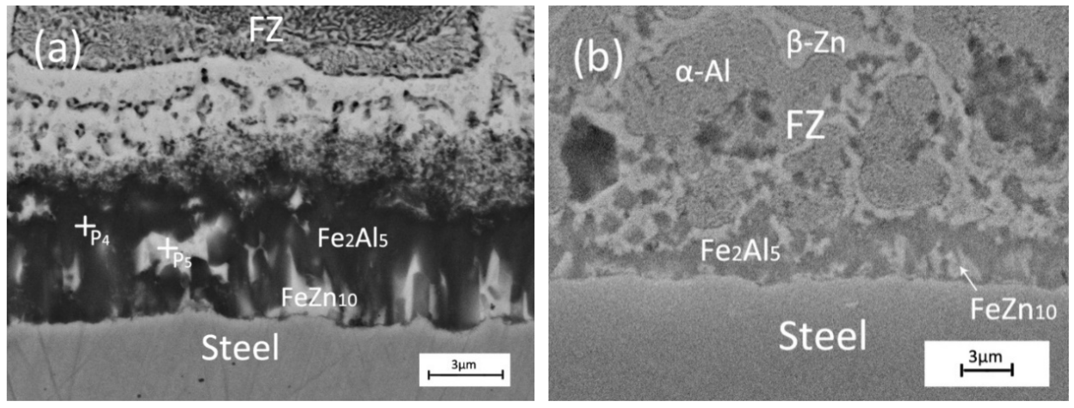
For the Al/bare steel joint, a homogeneous reaction layer consisting of Fe2Al5 and FeZn10 was formed at the interface.
(3)
The microhardness of the interfacial reaction layer in an Al/Ni-coated steel joint is 278–318 HV, which is much lower than that of the Al/bare steel joint (~512–526 HV).
(4)
The fracture load of the Al/bare steel joint was only 743 ± 65 N, but it improved to 932 ± 92 N by adding the Ni coating.
(5)
The Ni coating acted a physical barrier to avoid the direct mixing of elements Fe and Al, which inhibited the formation of brittle Fe2Al5. Hence, it led to the improvement of joint strength.

Author Contributions

J.Y. conceived and performed the experiments, analyzed the data, and wrote the paper. N.Z., Z.Y. and Y.L. provided the experimental materials and laboratory equipment, and directed the research. Z.Z., W.Z., J.C. and P.Z. contributed to the discussion and interpretation of the results.

Acknowledgments

This work was supported by National Natural Science Foundation of China (grant Nos. 51665038, 51775091 and 51605276), Key Project of the Natural Science Foundation of Jiangxi Province (grant No. 20171ACB21011) and the Science and Technology Planning Project of Sichuan Province (grant No. 2018GZ0284).

Conflicts of Interest

The authors declare no conflicts of interest.

References

  1. Guo, W.; Wan, Z.; Peng, P.; Jia, Q.; Zou, G.; Peng, Y. Microstructure and mechanical properties of fiber laser welded QP980 steel. J. Mater. Process. Technol. 2018, 256, 229–238. [Google Scholar] [CrossRef]
  2. Xia, H.; Zhao, X.; Tan, C.; Chen, B.; Song, X.; Li, L. Effect of Si content on the interfacial reactions in laser welded-brazed Al/steel dissimilar butted joint. J. Mater. Process. Technol. 2018, 258, 9–21. [Google Scholar] [CrossRef]
  3. Urbikain, G.; Perez, J.M.; López de Lacalle, L.N.; Andueza, A. Combination of friction drilling and form tapping processes on dissimilar materials for making nutless joints. Proc. Inst. Mech. Eng. Part B J. Eng. Manuf. 2018, 232, 1007–1020. [Google Scholar] [CrossRef]
  4. Ding, Y.; Shen, Z.; Gerlich, A.P. Refill friction stir spot welding of dissimilar aluminum alloy and AlSi coated steel. J. Manuf. Process. 2017, 30, 353–360. [Google Scholar] [CrossRef]
  5. Mirza, F.A.; Macwan, A.; Bhole, S.D.; Chen, D.L.; Chen, X.G. Effect of welding energy on microstructure and strength of ultrasonic spot welded dissimilar joints of aluminum to steel sheets. Mater. Sci. Eng. A 2016, 668, 73–85. [Google Scholar] [CrossRef]
  6. Acarer, M.; Demir, B. An investigation of mechanical and metallurgical properties of explosive welded aluminum–dual phase steel. Mater. Lett. 2008, 62, 4158–4160. [Google Scholar] [CrossRef]
  7. Yang, J.; Li, Y.L.; Zhang, H. Microstructure and mechanical properties of pulsed laser welded Al/steel dissimilar joint. Trans. Nonferr. Met. Soc. China 2016, 26, 1002–1010. [Google Scholar] [CrossRef]
  8. Cao, R.; Chang, J.H.; Huang, Q.; Zhang, X.B.; Yan, Y.J.; Chen, J.H. Behaviors and effects of Zn coating on welding-brazing process of Al-Steel and Mg-steel dissimilar metals. J. Manuf. Process. 2018, 31, 674–688. [Google Scholar] [CrossRef]
  9. Chen, J.; Li, J.; Amirkhiz, B.S.; Liang, J.; Zhang, R. Formation of nanometer scale intermetallic phase at interface of aluminum-to-steel spot joint by welding–brazing process. Mater. Lett. 2014, 137, 120–123. [Google Scholar] [CrossRef]
  10. Yang, J.; Yu, Z.; Li, Y.; Zhang, H.; Guo, W.; Zhou, N. Influence of alloy elements on microstructure and mechanical properties of Al/steel dissimilar joint by laser welding/brazing. Weld. World 2018, 62, 427–433. [Google Scholar] [CrossRef]
  11. Wang, C.; Cui, L.; Mi, G.; Jiang, P.; Shao, X.; Rong, Y. The influence of heat input on microstructure and mechanical properties for dissimilar welding of galvanized steel to 6061 aluminum alloy in a zero-gap lap joint configuration. J. Alloys Compd. 2017, 726, 556–566. [Google Scholar] [CrossRef]
  12. Qin, G.; Ji, Y.; Ma, H.; Ao, Z. Effect of modified flux on MIG arc brazing-fusion welding of aluminum alloy to steel butt joint. J. Mater. Process. Technol. 2017, 245, 115–121. [Google Scholar] [CrossRef]
  13. Tan, C.; Lu, Q.; Chen, B.; Song, X.; Li, L.; Feng, J.; Wang, Y. Influence of laser power on microstructure and mechanical properties of laser welded-brazed Mg to Ni coated Ti alloys. Opt. Laser Technol. 2017, 89, 156–167. [Google Scholar] [CrossRef]
  14. Sun, M.; Niknejad, S.T.; Zhang, G.; Lee, M.K.; Wu, L.; Zhou, Y. Microstructure and mechanical properties of resistance spot welded AZ31/AA5754 using a nickel interlayer. Mater. Des. 2015, 87, 905–913. [Google Scholar] [CrossRef]
  15. Yang, J.; Yu, Z.; Li, Y.; Zhang, H.; Zhou, N. Laser welding/brazing of 5182 aluminium alloy to ZEK100 magnesium alloy using a nickel interlayer. Sci. Technol. Weld. Join. 2018, 1–8. [Google Scholar] [CrossRef]
  16. Oliveira, J.P.; Panton, B.; Zeng, Z.; Andrei, C.M.; Zhou, Y.; Miranda, R.M.; Fernandes, F.B. Laser joining of NiTi to Ti6Al4V using a niobium interlayer. Acta Mater. 2016, 105, 9–15. [Google Scholar] [CrossRef]
  17. Chen, S.; Huang, J.; Ma, K.; Zhang, H.; Zhao, X. Influence of a Ni-foil interlayer on Fe/Al dissimilar joint by laser penetration welding. Mater. Lett. 2012, 79, 296–299. [Google Scholar] [CrossRef]
  18. Chen, S.; Huang, J.; Ma, K.; Zhao, X.; Vivek, A. Microstructures and mechanical properties of laser penetration welding joint with/without Ni-foil in an overlap steel-on-aluminum configuration. Metall. Mater. Trans. A 2014, 45, 3064–3073. [Google Scholar] [CrossRef]
  19. Yang, J.; Li, Y.; Zhang, H.; Guo, W.; Weckman, D.; Zhou, N. Dissimilar laser welding/brazing of 5754 aluminum alloy to DP 980 steel: Mechanical properties and interfacial microstructure. Metall. Mater. Trans. A 2015, 46, 5149–5157. [Google Scholar] [CrossRef]
  20. Li, L.; Tan, C.; Chen, Y.; Guo, W.; Hu, X. Influence of Zn coating on interfacial reactions and mechanical properties during laser welding-brazing of Mg to steel. Metall. Mater. Trans. A 2012, 43, 4740–4754. [Google Scholar] [CrossRef]
  21. Yang, J.; Li, Y.L.; Zhang, H.; Guo, W.; Zhou, Y. Control of interfacial intermetallic compounds in Fe–Al joining by Zn addition. Mater. Sci. Eng. A 2015, 645, 323–327. [Google Scholar] [CrossRef]
  22. Peng, H.; Xu, S.; Wang, J.; Wu, C.; Tu, H.; Su, X. The 600 °C Isothermal Section of the Al-Ni-Zn Ternary System. J. Phase Equilib. Diffus. 2017, 38, 151–159. [Google Scholar] [CrossRef]
  23. Raghavan, V. Al-Fe-Zn (Aluminum-Iron-Zinc). J. Phase Equilib. Diffus. 2013, 34, 32–34. [Google Scholar] [CrossRef]
  24. Okamoto, H. Ni-Zn (nickel-zinc). J. Phase Equilib. 2003, 24, 280–281. [Google Scholar] [CrossRef]
  25. Okamoto, H. Al-Ni (aluminum-nickel). J. Phase Equilib. Diffus. 2004, 25, 394. [Google Scholar] [CrossRef]
Figure 1. (a) Schematic of the Ni electrodeposition process on steel; (b) cross-section of the Ni electrodeposited layer on the steel substrate.
Applsci 08 00922 g001
Figure 2. (a) Schematic description of the laser welding/brazing layout used for joining the aluminum alloy to Ni-coated steel sheets in the lap joint configuration and (b) schematic illustration of the tensile-shear test samples.
Applsci 08 00922 g002
Figure 3. Laser Al/Ni-coated steel joint: (a) top surface appearance and (b) cross-section.
Applsci 08 00922 g003
Figure 4. Backscattered electron image (BEI) images and energy-dispersive X-ray spectrometer (EDS) line scanning of the laser Al/Ni-coated steel joint at different zones: (a,c) direct irradiation zone; (b,d) fusion zone (FZ) root.
Applsci 08 00922 g004
Figure 5. BEI images of laser Al/bare steel joint at different zones: (a) direct irradiation zone; (b) FZ root.
Applsci 08 00922 g005
Figure 6. Hardness distribution across the interface of the Al/bare steel joint and Al/Ni-coated steel joint.
Applsci 08 00922 g006
Figure 7. Fracture surface morphology and X-ray diffraction (XRD) pattern of the Al/Ni-coated steel joint: (a) FZ side at the direct irradiation zone; (b) steel side at the direct irradiation zone; (c) FZ side at the FZ root; (d) steel side at the FZ root and (e) XRD pattern at the FZ side.
Applsci 08 00922 g007aApplsci 08 00922 g007b
Figure 8. Fracture surface morphology and XRD patterns of the laser Al/bare steel joint: (a) FZ side; (b) steel side; and (c) XRD pattern at the FZ side.
Applsci 08 00922 g008
Figure 9. Schematic of joining mechanism: (a) melting of filler metal and its spreading on Ni coating; (b) partial melting of the Al base metal, excessive dissolution of Ni, and element mutual diffusion; (c) formation of Ni5Zn21 at the direct irradiation zone; (d) formation of layered and dispersed Al3Ni at different zones; and (e) fractured joint.
Applsci 08 00922 g009
Table 1. Chemical composition of the materials in wt.%.
MaterialsMgCrMnSiCuZnTiFeMoCAlB
DP 980 steel-0.152.10.05---Bal.0.350.1350.450.007
Al 57542.6–3.60.30.50.40.10.20.150.4--Bal.-
Zn-22Al----<0.003Bal.-<0.02--22-
Table 2. Mechanical properties of the base materials.
MaterialsYield Strength (MPa)Ultimate Strength (MPa)Elongation (%)
DP980 steel666 ± 361005 ± 712.5 ± 0.7
Al 575485 ± 11239 ± 316.2 ± 1.3
Table 3. Composition of Ni electroplating solution and electroplating parameters.
Plating Solution Composition (g/L)Electrodeposition Parameters
NiSO4·6H2O180Cathode current density300 mA/mm2
NH4Cl25Temperature43–60 °C
H3BO330pH5.6–5.9
Time10–25 min
Table 4. Experimental parameters used in the laser welding/brazing.
Welding ParametersValue
Laser power (kW)2.6
Defocusing amount (mm)3
Welding speed (m/min)0.5
Flow rate of shielding gas Ar (L/min)15
Table 5. Energy-dispersive X-ray spectrometer (EDS) analysis of the marked points in Figure 4 and Figure 5 in at.%.
PointAlFeZnNiPossible Phases
P16.1 ± 0.7-74.4 ± 0.319.4 ± 0.5Ni5Zn21
P268.9 ± 0.9-3.5 ± 0.327.6 ± 0.4Al3Ni
P369.5 ± 5.1-7.2 ± 0.923.2 ± 4.5Al3Ni
P471.6 ± 0.523.8 ± 0.14.6 ± 0.5-Fe2Al5
P510.8 ± 3.69.7 ± 1.879.5 ± 3.1-FeZn10
Table 6. EDS analysis of the marked areas in Figure 7 in at.%.
AreaAlZnNiPossible Phases
A12.9 ± 0.474.0 ± 2.723.1 ± 3.0Ni5Zn21
A2--100.0Ni
A34.3 ± 0.572.2 ± 1.821.9 ± 1.6Ni5Zn21
A464.5 ± 2.58.5 ± 3.327.0 ± 1.3Al3Ni
A566.1 ± 2.310.0 ± 3.123.9 ± 2.2Al3Ni

