Article

Reliability Study on FRP Composites Exposed to Wet-Dry Cycles

The School of Civil Engineering, Wuhan University, Wuhan 430072, China
*
Author to whom correspondence should be addressed.
Appl. Sci. 2018, 8(6), 892; https://doi.org/10.3390/app8060892
Submission received: 14 May 2018 / Revised: 24 May 2018 / Accepted: 29 May 2018 / Published: 30 May 2018
(This article belongs to the Special Issue Emerging Construction Materials and Sustainable Infrastructure)

Abstract

:
Due to lack of research data on the rates of deterioration of FRP properties under a harsh environment exposure, it was pointed out in the design guidelines that the durability of FRP needs to be further developed. Therefore, in this study, 48 FRP samples were tested under wet-dry cycles exposure. The effect of wet-dry cycling times on the failure modes, tensile strength, and the probability distribution of different FRP (GFRP and CFRP) composite specimens were investigated. The experimental results showed that the wet-dry cycles have a significant adverse influence on the tensile strength, have a certain adverse effect on the elongation, and a very limited influence on the elastic modulus of FRP. According to the experimental results, a probability analysis was conducted on the degradation of tensile strength. Five widely used test methods were adopted to verify the possible distribution types of tensile strength, and a reliability index β was then calculated. Subsequently, the effects of the design tensile strengths of ACI-440, TR-55, GB 50608-2010, GB 50367-2013, European Fib Bulletin 14 and Italian CNR guidelines on the β were investigated. The investigation illustrates that only the design value of the TR-55 code can guarantee sufficient long-term safety of a CFRP composite, whereas all the six codes cannot guarantee the long-term safety of a GFRP composite and the partial safety factors in these codes are still not conservative. Therefore, a more conservative safety factor was suggested. Moreover, the design value of tensile strength needs to be further conservative when the standard deviation of the load is large.

1. Introduction

During the last decades, external bonding of fiber-reinforced polymers (FRP) has been widely used to strengthen or retrofit deteriorated civil engineering structures. This is mainly due to its light weight, excellent tensile strength, resistance to corrosion, durable construction and easy tailoring [1,2]. However, many questions related to its durability of service life are still unanswered. Previous studies have focused on the short-term characteristics of FRP composite materials (i.e., fibers and resin) [3,4,5,6,7]. The research data on the rates of deterioration of the properties, such as tensile strength and modulus, under multiple harsh environments exposure (e.g., marine environment, acid rain erosion, high temperature, and sustained load coupling) is insufficient [8]. In the design guidelines of ACI 440.2R-08, it was pointed out that some research related to the durability of FRP materials and standardized test methods with an accent on durability testing, need to be further developed. These facts motivated the development of a study that would address durability issues of FRP composite materials under harsh environments.
External bonding FRP in civil engineering may be exposed to harsh environmental conditions during the whole service life including, freeze-thaw cycles, extreme temperatures, solar radiation and aggressive chemical attack, and wet-dry cycles. Freeze-thaw exposure was identified as a severe temperature-related threat by the Civil Engineering Research Foundation (CERF) [9]. Significant loss in the mechanical properties and integrity of FRP was found after freeze-thaw cycles exposure due to fiber/matrix debonding and matrix microcracking [10,11]. The loss will increase further under the multiple environmental coupling effects of freeze-thaw cycles, salty water, deionized water, wet-dry cycle, or sustained loading. The hygrothermal exposure will significantly accelerate the moisture-induced deterioration process and relaxation process of FRP materials [12,13]. Nardone et al. [14] tested 63 glass FRP (GFRP) or carbon FRP (GFRP) coupons to study the effects of extreme service temperature or freeze–thaw cycles on FRP mechanical properties. The results showed that strength and elastic modulus mildly decreased when the temperature was raised from −15 to +36 °C; while the ultimate strain remained almost constant. Furthermore, freeze–thaw cycles ranging from 30 to 80 had a negligible influence on the mechanical properties of CFRP laminates, while 210 cycles resulted in slight reductions in tensile strength and an ultimate strain equivalent of 9% and 13%, respectively. Rivera et al. [15] found that freeze–thaw cycles under both dry and wet conditions typically have a detrimental effect on the strength and to a lesser degree on the stiffness of carbon and E-glass composites. The studies [16,17] have demonstrated that wet-dry cycles could decrease the ultimate load of various FRP composites, and combined effects with other environments will be more significant. Hulatt et al. [18] exposed FRP coupons to wet-dry cycles of using tap water and road salt solutions. It was found that the ultimate failure stress decreased in tap water but increased in the salt solution. When a sustained loading was applied simultaneously, the creep deformation increased the molecular spacing which makes water molecules and NaCl molecules more easily invaded adhesive, thus causing greater deterioration of the reliability and durability of the structural elements [19]. Helbling et al. [20,21] reported that sustained bending strain had no influence on moisture uptake, but could cause severe fiber/matrix interfacial debonding, in addition to fiber pitting and cracking.
In summary, when the FRP reinforcement system is in service in a harsh environment, its mechanical properties are continuously degraded. If the design is based on short-term mechanical properties of the FRPs, the structure will have a large failure probability. Therefore, most guides for structural design suggest using partial safety factors and an environmental reduction to consider the degradation of the materials. Taking the tensile strength of FRPs as an example, it is one of the most important control parameters for the flexural design of FRP-strengthening concrete beams and the design of FRP-constraining concrete columns. The codes assume certain values for the design loading and the design tensile strength of the materials to assess the effect of a particular limit state on the structure. The variability of tensile is taken into account by assuming a characteristic tensile strength. In the Concrete Society in the United Kingdom (TR-55) [22], the characteristic tensile strength was obtained from the FRP system manufacturer, and calculated by the mean tensile strength of a sample of test specimens minus three times the standard deviation. The design tensile strength is determined by dividing the characteristic tensile strength by an environmental factor, CE. When CFRP material was used in the cases of exterior exposure (such as retrofitting bridges and piers) or aggressive environments (such as chemical plants), the CE was taken as 0.85, and the value of CE were 0.65 and 0.50, respectively, for exterior exposure and aggressive environments. Most of these safety factors are determined by the probability analysis method and the reliability theory. Three times the standard deviation for characteristic strength in TR-55 can provide a 99.87% probability that the indicated ultimate tensile strengths are exceeded. The environmental factor is a limit value which can ensure the reliability of the structure is always greater than the allowable minimum reliability during the service period. As stated in the specification, due to the lack of relevant research results about the durability of FRPs, these safety factors can be refined as more research information is developed and becomes available. Wang et al. [23] developed a probability-based limit state standard for the design and evaluation of RC structures strengthened by externally bonded CFRP composites. They found that a separate resistance factor of 0.75 should be applied to the nominal strength of the CFRP to achieve a reliability index of approximately 3.0, and that a partial factor should be applied separately to each strength variable if the strength is represented by a sum of random variables. However, their study of resistance criteria did not take environmental factors into account.
With this background, a total of 48 FRP samples, including 24 CFRP samples and 24 GFRP samples were tested to evaluate the deterioration of the FRP properties under long-term wet-dry cycles exposure. The degradation law of mechanical properties of FRP with the number of wet-dry cycles, the possible distribution types and the reliability index β were obtained. Subsequently, a reliability analysis was conducted on the effects of the mean and standard deviation of a load on β. The mean values are calculated from the related codes, such as ACI-440 [24], TR-55 [22], GB 50608-2010 [25] and GB 50367-2013 [26]. By comparing the reliability of the FRP composite after many times of wet-dry cycles and the allowable reliability index, it is determined whether the design values of each code can guarantee the long-term safety of the FRP composite.

2. Materials and Methods

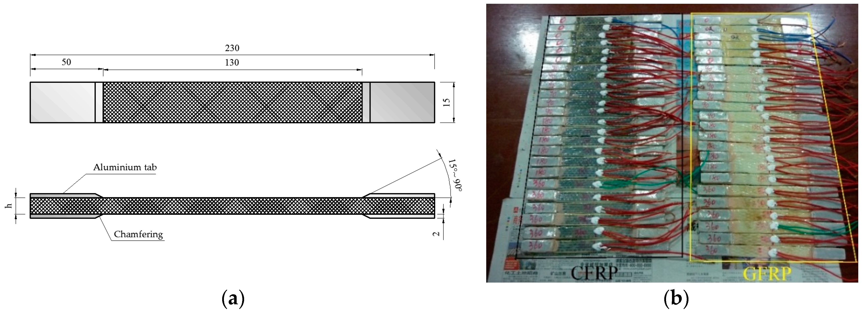
2.1. Specimen Preparation

A total of 48 FRP samples, including 24 CFRP samples and 24 GFRP samples, were designed as shown in Table 1. The CFRP samples were cut from a uni-directional sheet with a unit weight of 300 g/m2 made of carbon fibers. The nominal thickness, length and width of the CFRP were 0.111 mm, 230 mm and 15 mm, respectively, as shown in Figure 1. The GFRP samples were cut from a glass fiber sheet with a unit weight of 600 g/m2 and the nominal thickness was 0.169 mm. The length and width of the GFRP were the same with the CFRP samples. The type of glass was E-Glass. WSX epoxy resin was used as the bond layer, which is a two-part epoxy saturant mixed resin A and hardener B in a 4:1 weight ratio. The mechanical properties of the WSX resin provided by the manufacturer show that its tensile strength, Young’s modulus, compressive strength, flexural strength and elongation are more than 40 MPa, 2.5 GPa, 70 MPa, 50 MPa and 1.5%, respectively. These mechanical properties of resin are fully satisfied with the requirements of the code named: Safety appraisal code for application of engineering structural strengthening materials GB 50728-2011 [27], that limits the minimum values of 30 MPa, 2.5 MPa, 65 MPa, 45 MPa and 1.2%, respectively. The prepared epoxy resin had a pot life of 45 min and a full cure time of 7 d at 25 °C from the production statement. The glass transition temperature Tg was about 105 °C. The resin will have viscous flow properties when the service temperature exceeds Tg and the micro-mechanical viscoelastic properties of FRP composite materials will need to be considered [28,29]. In the test period, the range of the water temperature and ambient temperature (test temperature) is 0 °C~33 °C, which is far less than Tg. Therefore, the effect of temperature on the mechanical properties of FRP is neglected in this study. The ends of the FRP samples are attached to a reinforcing aluminous gasket to apply the load. The width, length and thickness of the aluminous gasket are 15 mm, 50 mm, and 2 mm. The aluminum surfaces need to be roughened to ensure a good fit with FRP before bonding. At the same time, the aluminum gasket must be chamfered to reduce the shear stress and peeling stress near the end of the test piece, thus preventing the specimen from breaking near the end.
The prepared FRP samples were fully immersed in a sink filled with 5% NaCl water, which simulated seawater, for 12 h and then accelerative blow-dried for another 12 h per cycle. The wet-dry cycle is achieved by using a water pump to pump water from one sink to another, and pumping the water back to the first tank 12 h later. The blow-dried conditions were used to increase the flow of wind speed to accelerative specimens drying. For reference, 90, 180, and 360 wet-dry cycles were considered. Once accomplishing the predetermined exposure cycles, the coupons were placed in the lab to air dry. A longitudinal strain gauge is then attached to the surface of the sample and the data is automatically collected by a computer.

2.2. Test Apparatus

After the FRP specimen reaches the predetermined number of wet-dry cycles, a 2 mm × 1 mm strain gauge is attached to the middle of the samples, and then the FRP samples will be tested according to ASTM D3039 [30]. The loading rate was set as 2 mm/min, and the applied load and FRP strain values during loading are recorded by computer.

3. Results

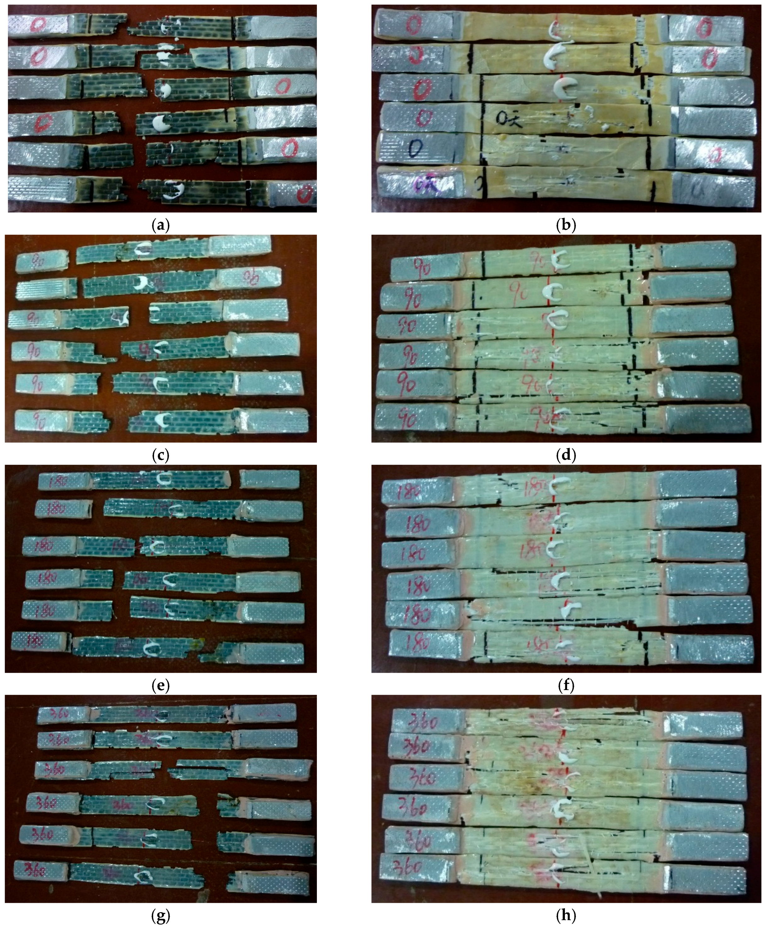
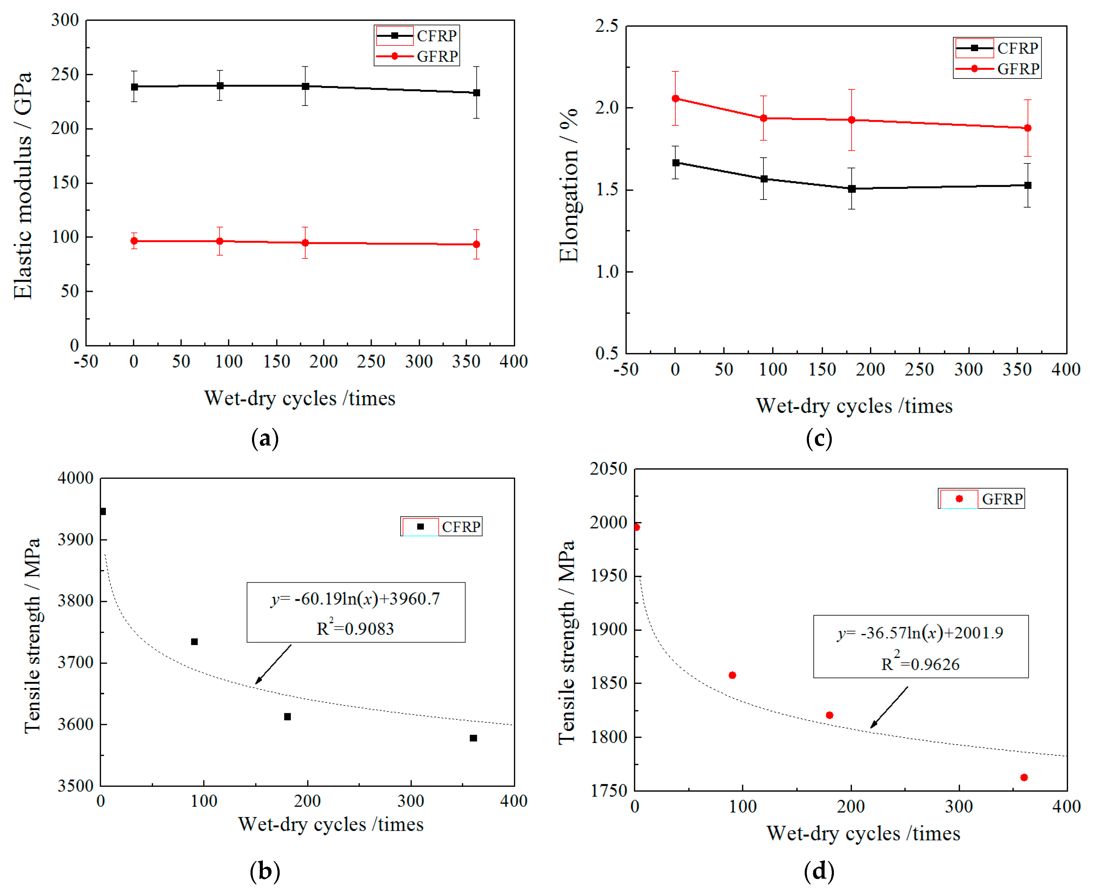
3.1. Experimental Results

The FRP specimen suddenly breaks when the tension reaches a certain value. The failure is brittle fracture, and the failure modes basically include three types: Central fracture, angled fracture and splitting failure, as shown in Figure 2. Most of the CFRP samples fail by central fractures and corner fractures, whereas the GFRP samples are accompanied by splitting failure in addition to fracture failure. The location of the fracture damage is relatively random and there is no obvious regularity. The failure modes of FRP samples at different corrosion times are also not significantly different.
The test results of FRP’s mechanical properties are listed in Table 1 and plotted in Figure 3. In which, the Young’s modulus was computed between the longitudinal strain range of 1000–3000 με. The elongation has been computed as the ultimate tensile strength divided by the Young’s modulus. It can be found that wet-dry cycles have almost no effect on the elastic modulus of FRP, but its standard deviation has an increasing trend with the increase of the number of wet-dry cycles. Under 360 times of wet-dry cycles, the elastic modulus of CFRP and GFRP are only reduced by 0.847% and 3.35%, respectively. It can also be seen that the wet-dry cycles have an adverse effect on the tensile strength of CFRP and GFRP. The tensile strength decreases approximately exponentially with the increase in the number of wet-dry cycles. The decreasing rate is fast in the early stage, and becomes slow in the following stage. Under 360 times of wet-dry cycles, the tensile strengths of CFRP and GFRP decreased by 9.32% and 11.98%, respectively. It also indicates that the corrosion resistance of CFRP is better than that of GFRP under wet-dry cycles. The elongation rates of CFRP and GFRP decreased under wet-dry cycles exposure, but only in the early stage, and the elongation of CFRP and GFRP did not change significantly in the later period.
In summary, wet-dry cycles have a significant adverse influence on the tensile strength, have a certain adverse effect on the elongation, and a very limited influence on the elastic modulus of FRP. Moreover, GFRP is more susceptible to the wet-dry cycle exposure than CFRP.

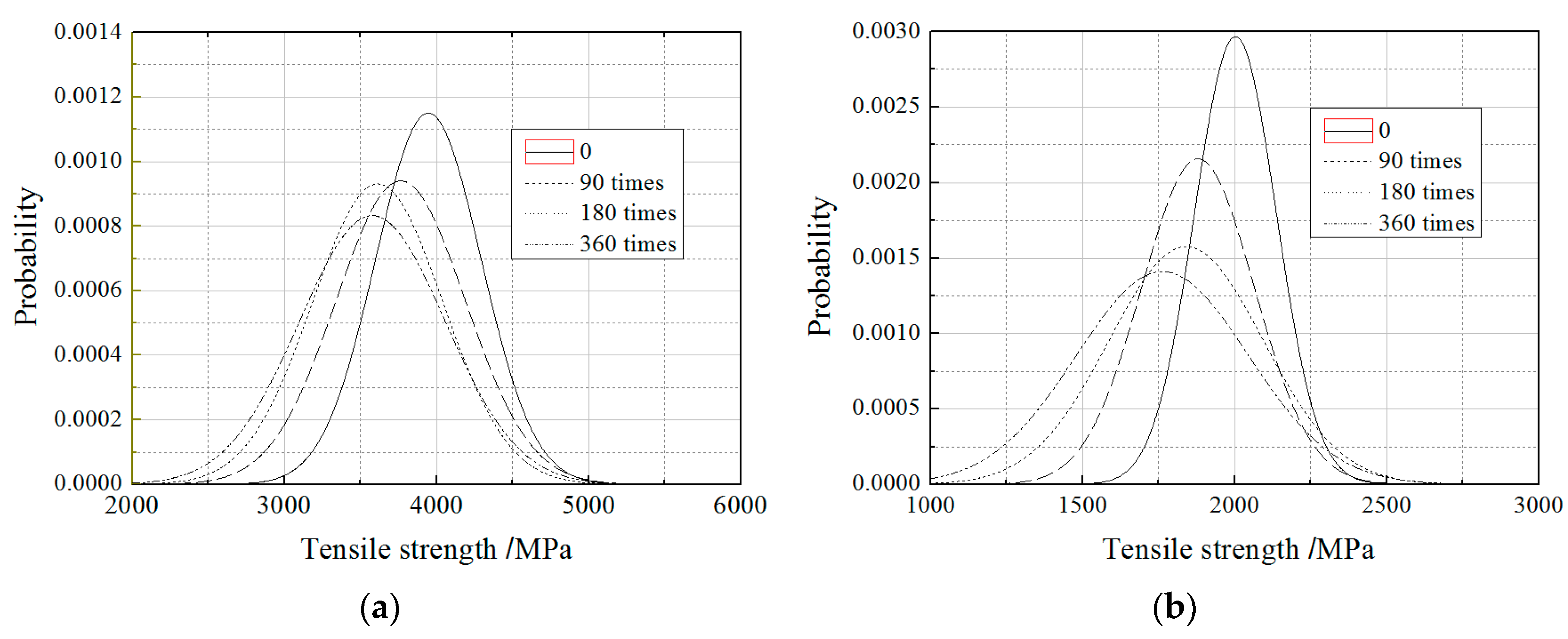
3.2. Probability Distribution Type

The above results show that the tensile strength of FRP is more sensitive to the environment, and its degradation is also more random, thus the variability of tensile strength need to be analyzed emphatically. The common distribution types for reliability analysis of FRP composites include Normal, Lognormal, Weibull and Gamma distribution. In this paper, these representative distribution types were chosen to fit statistical distributions of the data. In order to determine which distribution best fits the data, five widely used test methods, Shapiro-Wilk (S-W test), Kolmogorov-Smirnov (K-S test), Cramer-von Mises (C-M test), Anderson-Darling (A-D test) and Chi-Square (test), were adopted, as shown in Table 2.
The goodness of fit (p) for the strength of FRP with/without wet-dry cycles exposure was listed in Table 3a–d. The size of the p value indicates the degree of coincidence for each probability distribution type. The larger the p value, the greater the probability that the sample will obey some distribution. In this paper α = 0.1 was adopted as the significance level, so when p > 0.1, the sample is considered to fit a certain distribution. According to Table 3a, all of the four distribution types fit the tensile strength of CFRP without wet-dry cycles exposure very well, and the best fits are considered to be the Normal distribution and Weibull distribution due to the larger p. As for the GFRP without wet-dry cycles exposure as shown in Table 3b, all p values calculated by the test for the four distributions were less than 0.1. However, for the other test, all p values of Normal distribution, Lognormal distribution and Weibull distribution were obvious, larger than 0.1. Meanwhile, the p values of Normal distribution and Weibull distribution were larger than Lognormal distribution. This indicates that the tensile strength of the FRP without wet-dry cycles exposure is well fit to Normal distribution and Weibull distribution, which is consistent with the conclusions obtained by other scholars.
According to Table 3c,d, the probability distribution of FRP tensile strength is not significantly affected by the wet-dry cycles exposure. The tensile strength of CFRP is better subjected to Normal distribution and Weibull distribution. For the tensile strength of GFRP, except for the test, the other test methods are subjected to Lognormal distribution and Gamma distribution. Under each effective test, the Normal distribution and Weibull distribution are well obeyed. According to the size of the p value, the fitting degree of Normal distribution and Weibull distribution is better than that of Lognormal distribution and Gamma distribution, while the fitting degree of Normal distribution and Weibull distribution is very close.

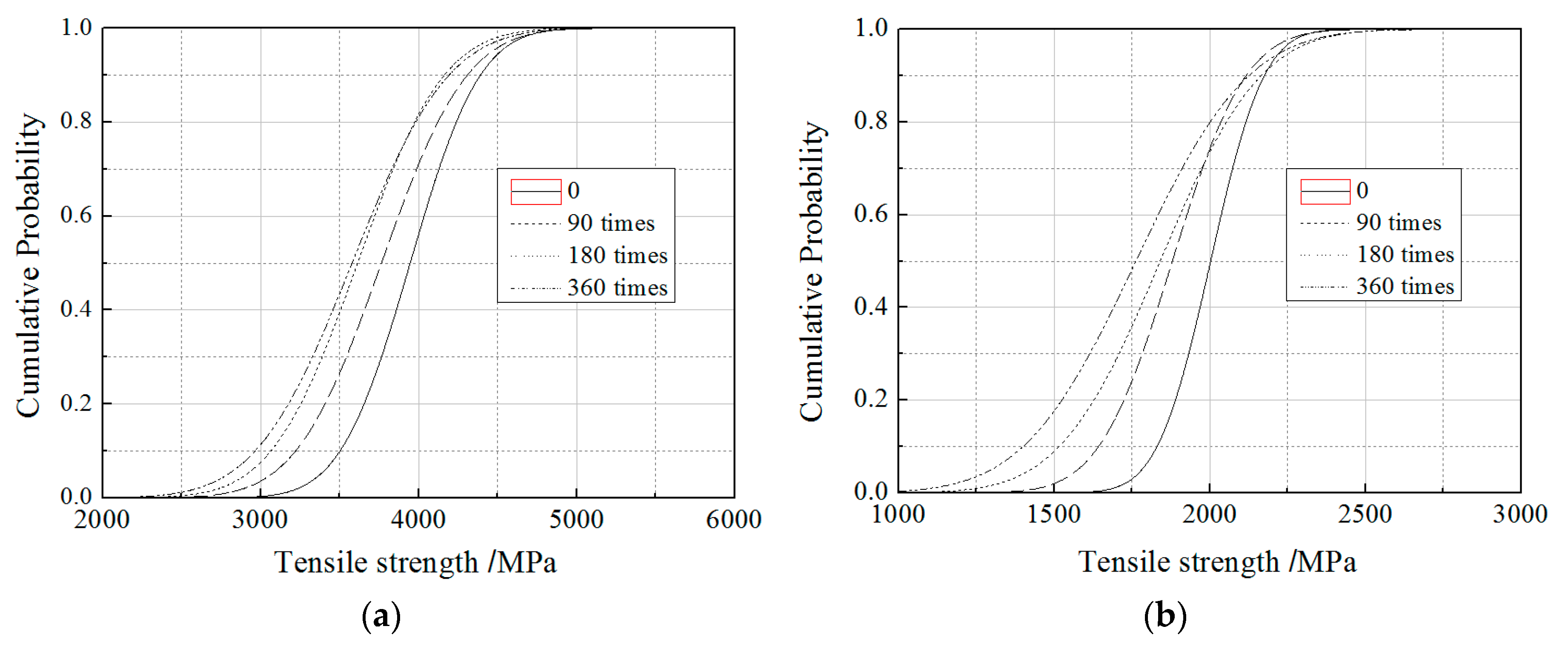
3.3. Probability Distribution

According to the results of the probability distribution, the tensile strength of the FRP materials with/without the wet-dry cycles all fit the Normal distribution and the Weibull distribution. However, the probability distributions of FRP tensile strength under each condition are taken as Normal distribution because of its simple computational modeling. When the distribution type is taken as Normal distribution, the probability distribution chart and the cumulative distribution chart of the FRP tensile strength can be plotted in Figure 4 and Figure 5, where the mean and standard deviation of the tensile strength of CFRP and GFRP were obtained from the experimental results. As shown in the figures, the peaks of CFRP and GFRP move to the left of the coordinate axis with the increase of the wet-dry cycles, and the shapes become more and more flat. The extent of this change from 0 to 90 cycles is significantly greater than from 180 to 360 cycles. In comparison, GFRP is more sensitive to wet-dry cycles than CFRP.

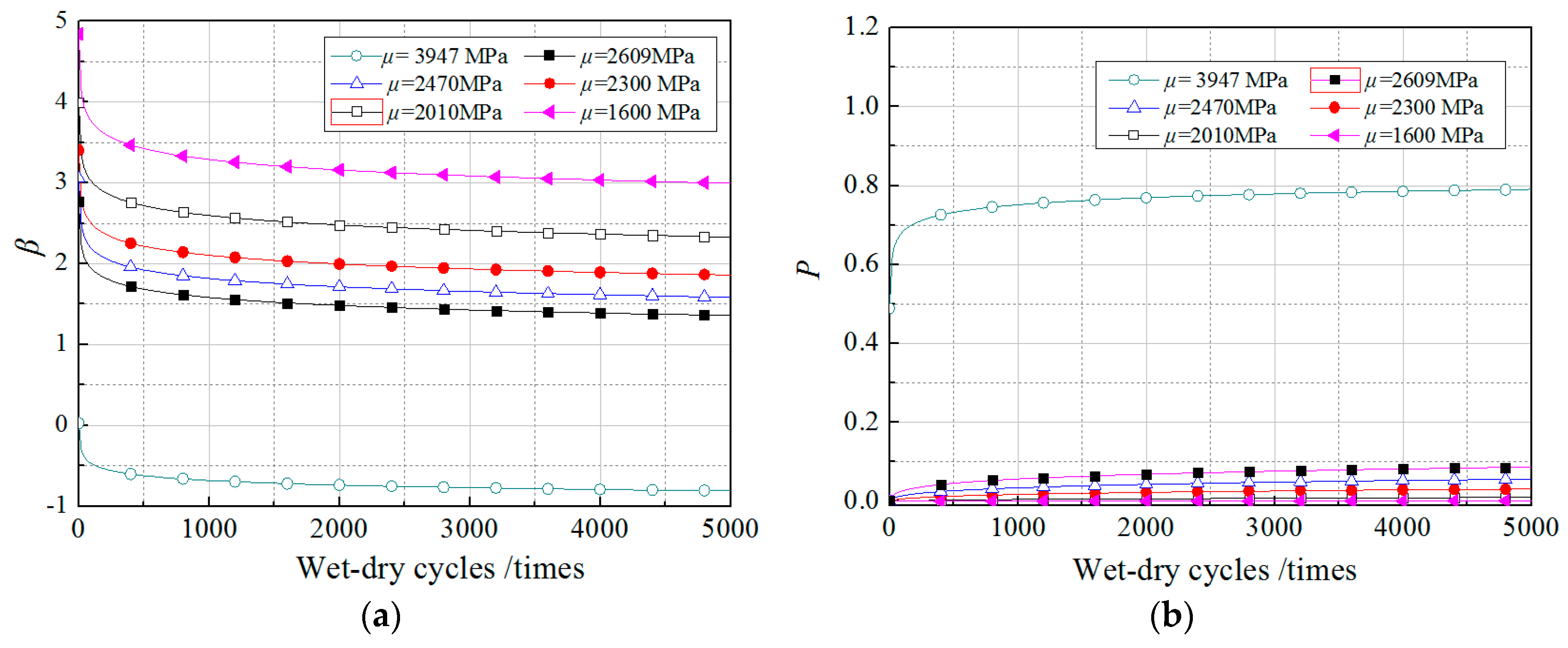
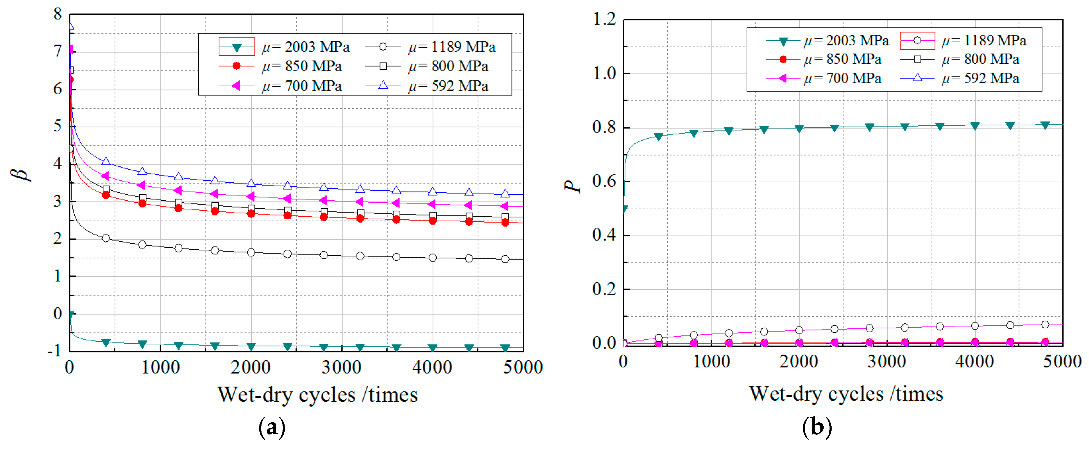
3.4. Reliability Analysis of FRP Strength

The limit state function or performance equation for FRP strength can be represented by the following equation:
Z = g ( R , S ) = R S = 0
in which, R is the random resistance and S is the load effect.
Meanwhile, the limit state equation for the degradation of FRP strength can be expressed as:
Z = g ( T n , T c ) = T n ( N ) T c ( N ) = 0
in which, Tn(N) and Tc(N) are the resistance and load effect after wet-dry cycles and sustained loading exposure, respectively, and they all obey the Normal distribution according to Section 3.3.
Therefore, the probability of degradation of the FRP strength after n time wet-dry cycles is:
P ( N ) = P ( g ( T n , T c ) 0 ) = P ( T n ( N ) T c ( N ) )
When the mean and standard deviation of Tn(N) are assumed to be mn(N) and σn(N), and the mean and standard deviation of Tc(N) are mc(N) and σc(N), respectively, Tn(N) and Tc(N) can be converted into a standard normal distribution as:
T ^ n ( N ) = T n ( N ) m n ( N ) σ n ( N )
T ^ c ( N ) = T c ( N ) m c ( N ) σ c ( N )
Thus, the reliability index (β) is obtained according to second-order moment reliability method (SORM):
β = m n ( N ) m c ( N ) σ n 2 ( N ) + σ c 2 ( N )
The corresponding failure probability was calculated by P = Φ ( β ) , and the mean mc(N) and standard deviation σc(N) of the resistance were assumed to be constant and equal to the test value.
According to the Arrhenius method, a prediction equation has already been proposed to estimate the long-term deterioration of FRP materials, which has been proven in accuracy [7,11,31,32]. The equation for predicting the tensile strength of FRP materials is in the form:
f ( N ) = f 0 100 [ A ln ( N ) + B ]
where f(N) and f0 are the tensile strengths at N times cycles and without environment exposure, respectively. A is a constant denoting degradation rate; and B is a material constant, which reflects the early effects of post-cure progression. Based on test results, the mn(N) and σn(N) can be regressed from the fit of the experimental results as shown in Equations (8)–(11):
m n C ( N ) = m n C ( 1 ) 100 [ 1.520 ln ( N ) + 100 ]
m n G ( N ) = m n G ( 1 ) 100 [ 1.798 ln ( N ) + 100 ]
σ n C ( N ) = σ n C ( 1 ) 100 [ 0.057 ln ( N ) + 100 ]
σ n G ( N ) = σ n G ( 1 ) 100 [ 0.181 ln ( N ) + 100 ]
where mnc(N) and mnG(N) are the mean of CFRP and GFRP materials, respectively. σnc(N) and σnG(N) are the standard deviation of CFRP and GFRP materials, respectively. The R2 values obtained from fitting Equations (8)–(11) were 0.9083, 0.9131 0.9151, and 0.8092, respectively, which illustrated the regression equations were relatively accurate. The values of N in the equations were within the scope of the experimental research, ranging from 1 to 360 times. However, in the follow-up analysis of β, the equations were extended to predict the bond action beyond 360 times, but the precision of the prediction requires further examination by experimental data. Setting the load to the experimental ultimate tensile strength without wet-dry cycle exposure and substituting Equations (8)–(11) into Equation (6), the reliability index (β) and the corresponding failure probability P with the increase of wet-dry cycle times can be obtained and are plotted in Figure 6.
As shown in the figure, the curves of CFRP and GFRP can be divided into two stages. In the first stage, β rapidly reduced with the increase of wet-dry cycles, and then β decreased very slowly with the increase of wet-dry cycles when β reduced to a small value. The boundary value of two stages for both CFRP and GFRP is 1000 times. In the first stage, the reliability index of CFRP decreased from near 0 to −0.68, and the reliability index of GFRP decreased from near 0 to −0.77. However, in the second stage, when the number of wet-dry cycles changed from 1000 to 5000, the reliability index of CFRP and GFRP decreased by less than 0.10. The decreased tendency of β is similar to an exponential function. In addition, the reliability index of CFRP is greater than the reliability index of GFRP under any cycle, indicating that CFRP is more resistant to wet-dry cycle exposure than GFRP. From Figure 7b, under the ultimate tensile load of FRP without wet-dry cycle exposure, the failure probability of the FRP composite is up to 80% after long-term wet-dry cycle exposure. This illustrates that the failure risk of CFRP composites will continue to increase with the continuous erosion of the wet-dry cycle under the same load. Therefore, in order to ensure effectiveness of the FRP rehabilitation over the life of the structure, it is essential that the tensile strength for design is chosen keeping in mind not just the variation in value around the mean of the characteristic, but also the deterioration that would take place due to harsh environmental exposure.

4. Discussion

4.1. The Safety Factors for FRP

In common with most guides of practice for structural design, the design methods are based on limit-state philosophy, which means a structure will not become unfit for its intended use. It means the structure will not reach a limit state during its design life. Due to the continuous degradation of FRP composite under a harsh environmental exposure, a safety factor needs to be used in the structural design stage. The designer will need to assume certain values for the design loading and the design strength of the materials to assess the effect of a particular limit state on the structure. The variability of material properties is taken into account by assuming a characteristic strength. Usually, characteristic strength is taken as the value below which not more than 5% of test results lie. A similar approach is used to define the characteristic strength of FRP in the report, but the acceptable failure rate has been reduced to 1%.
In the guidelines of the American Concrete Institute ACI-440 [24], the design tensile strength, ffu, can be calculated by modifying the reported strength, ffu*, by an environmental factor, CE, as follows:
f fu = C E f fu *
where
f fu * = ( f u 3 σ )
where f u is the mean ultimate strength and σ is the standard deviation of the test population.
When CFRP material was used in the cases of exterior exposure (such as retrofitting bridges and piers) or aggressive environments (such as chemical plants), the CE was taken as 0.85, which indicates that the threshold to which the CFRP samples can degrade prior to being considered as below the design allowable is 0.85 f fu * . In comparison, the values of CE were 0.65 and 0.50, respectively, for exterior exposure and aggressive environments.
A similar restriction exists in the guidelines of the Concrete Society in the United Kingdom (TR-55) [22], the characteristic material properties be defined as follows:
f fk = ( f u 2 σ )
where ffm is the mean ultimate strength of the test population. The design strength is determined by dividing ffk by partial safety factors to account for strength at the ultimate limit state, γmf, and the recommended value of the manufacture factor, γmm, such that the design value is given by:
f fd = f fk γ mf γ mm
For CFRP material, γmf = 1.4 and γmm = 1.4, and for GFRP material, γmf = 1.95 and γmm = 1.05.
In the Chinese Technical Code for Infrastructure Application of FRP Composites (GB 50608-2010) [25], the design value fd is suggested to consider the degradation of FRP material properties and is determined by dividing the experimental ultimate strength with guarantee probability fk by similar partial safety factors (γf) to account for material type and the surrounding environment (γe). The equations described in the GB 50608-2010 are as follows,
f d = f k γ f γ e
f k = ( f u 1.645 σ )
where the values of γf are taken as 1.4 for CFRP and GFRP materials. The values of γe are taken as 1.2 and 1.6 for CFRP and GFRP materials, respectively, under ocean environment exposure. However, in another code in China (Code for design of strengthening concrete structure GB 50367-2013 [26]), the design values of tensile strength of CFRP and GFRP are limited to lower values 2300 MPa and 700 MPa, respectively. This not only considers the degradation of FRP materials, but also considers the degradation of the performance of concrete structures.
According to European Fib Bulletin 14 [33], the design tensile strength ffd,fib was calculated by:
f fd , fib = f fk , fib γ f ε fue ε fum
where ffk,fib is the characteristic strength and corresponds to the 5% fractile of the tensile strength. γf is the FRP material safety factor and suggested to be 1.35 and 1.50 for wet lay-up CFRP systems and GFRP systems, respectively. The ratio εfuc/εfum normally equals 1, as the effective ultimate FRP strain εfum expected in situ will not significantly differ from the mean strain εfum obtained through uniaxial tensile testing, and as small variations are accounted for in the FRP material safety factor γf.
The design tensile strength in Italian CNR guidelines [34] can be expressed as follows:
X d = η X k γ m
where η is a conversion factor accounting for environmental factors, and the values for GFRP and CFRP are 0.50 and 0.85, respectively. γm is the partial factor of FRP materials and is equal to 1.10.
The design values (f13) of tensile strength of FRP materials used in this study according to the four representative specifications were calculated and listed in Table 4. It is found that the GFRP design values in the four specifications are basically the same and range from 700 MPa to 1189 MPa, and the range of CFRP design values is relatively large with 1660 MPa to 2609 MPa.

4.2. The Effects of Mean Values of the Load

According to the above results, five representative mean values, 1660 MPa (ffu), 2010 MPa (ffd), 2300 MPa (f13), 2470 MPa (ffu or ffd,fib), 2609 MPa (Xd) and 3947 MPa ( f u ), are selected for the reliability analysis of CFRP, whereas 700 MPa (f13), 800 MPa (ffu, fd or Xd), 850 MPa (ffd), 1189 MPa (ffd,fib), and 2003 MPa ( f u ) were chosen for GFRP. The upper limit of the range is set as the test ultimate tensile strength ( f u ). The standard deviations of load for CFRP and GFRP were taken as the experimental values, which were 346.88 MPa and 134.48 MPa, respectively. The values of resistance were the same as those in the previous section; the reliability index can be calculated by the previous method as shown in Figure 7 and Figure 8.
According to Figure 7, when the mean of the load is taken as a different value, the reliability indices curves do not change significantly with the number of wet-dry cycles and can still be divided into two stages. However, the mean of the load has a great influence on the initial value of reliability indices (β0). The β0 is less than zero under f u , and the corresponding P has exceeded 50%. In contrast, under the design tensile strength of the four representative codes, the β0 are greater than 3.0, and they provide a safety probability of over 99.83%. In the subsequent wet-dry cycles exposure, the β decreases rapidly due to the continuous erosion of wet-dry cycles and tends to stabilize after 4000 cycles. In the four representative codes, only the β under ffd can always stay above 3.2, whereas the β under ffd will be less than 2.0. In the guideline of Unified standard for reliability design of building structures (GB 50068) [35], the minimum reliability index of brittle fracture structures is 3.2. According to this standard of the minimum reliability index 3.2, only the design value of the TR-55 code can guarantee sufficient long-term safety. As shown in Figure 8, the decline law in reliability of GFRP with increasing wet-dry cycles is basically consistent with CFRP. Similarly, under the design tensile strength of the four representative codes, the β0 are obviously greater than 3.2. However, after 4000 times of wet-dry cycle exposure, the β are less than 3.0 under the design values of all the four codes. This shows that the four codes cannot guarantee the long-term safety and the partial safety factors in these codes are still not conservative. After continuous trials, it was found that when γmm was changed from 1.05 to 1.5, the design strength (ffd) of TR-55 decreases to 592 MPa and the corresponding β values can always stay above 3.2. Therefore, the γmm was suggested to modify.

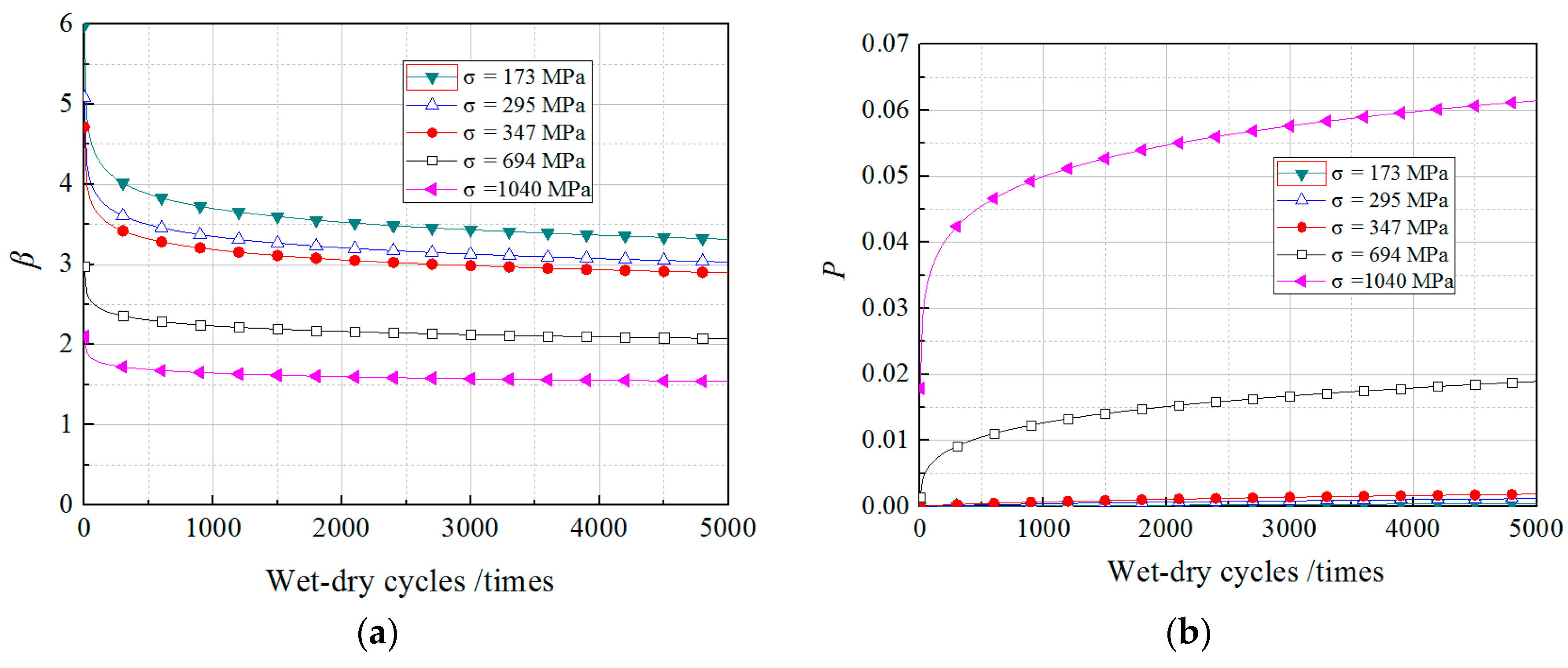
4.3. The Effects of Standard Deviations of the Load

In this study, the mean of the load for CFRP was taken as the design value (1600 MPa) of TR-55, and five representative mean values, 0.5σec, 0.85σec, 1.0σec, 2σec and 3σec, were chosen where σec is the test standard deviation of CFRP (346.88 MPa) without environmental exposure. The mean of the load for GFRP was taken as the design value (700 MPa) of GB 50367-2013, and five representative mean values, 0.5σeg, 0.85σeg, 1.0σeg, 2σeg and 3σeg, were chosen where σeg is the test standard deviation of GFRP (134.48 MPa) without environmental exposure. The values of resistance were the same as those in the previous section; the reliability index can be calculated by the previous method as shown in Figure 9 and Figure 10.
As shown in the Figures, the reliability of the FRP composite will visually decrease as the standard deviation of the load increases. When the standard deviation is lower than σeg, the difference in β with different standard deviations is slight and can always stay above 3.2. When the standard deviation is 2σeg or more, the β is less than 3.0 after 4000 times of wet-dry cycle exposure, and the failure probability increases very obviously. Therefore, the design value of tensile strength needs to be further conservative when the standard deviation of the load is relatively large.

5. Conclusions

Forty-eight FRP samples, including 24 CFRP samples and 24 GFRP samples, were tested to evaluate the deterioration of the FRP properties under long-term wet-dry cycles exposure. The results illustrate that the failure modes of FRP samples at different corrosion times are not significantly different. The wet-dry cycles have a significant adverse influence on the tensile strength, have a certain adverse effect on the elongation, and a very limited influence on the elastic modulus of FRP. Moreover, GFRP is more susceptible to the wet-dry cycle exposure than CFRP. In the probability analysis, the tensile strength of the FRP materials with/without the wet-dry cycles both fit the Normal distribution and the Weibull distribution. However, the probability distributions of FRP tensile strength under each condition are taken as Normal distribution because of its simple computational modeling. The decreased tendency of β with the increasing of wet-dry cycle is similar to an exponential function. In the beginning, β rapidly reduced with the increase of wet-dry cycles, and then β decreased very slowly with the increase of wet-dry cycles when β reduced to a small value. The boundary value of the two stages for both CFRP and GFRP is about 1000 times. Subsequently, through the analysis of the design tensile strength of ACI-440, TR-55, GB 50608-2010 and GB 50367-2013, European Fib Bulletin 14 and Italian CNR guidelines on the β, it is found that only the β of CFRP composite under the design value of the TR-55 code can always stay above 3.2, which means long-term safety can be guaranteed. However, for the GFRP composite, all the four codes cannot guarantee the long-term safety of the GFRP composite and the partial safety factors in these codes are still not conservative. The reliability of the FRP composite will visually decrease as the standard deviation of the load increases. When the standard deviation is 2σeg or more, the β is less than 3.0 under 4000 times wet-dry cycle exposure, and the failure probability increases very obviously. Therefore, the design value of tensile strength needs to be further conservative when the standard deviation of the load is large.

Author Contributions

S.L. and Y.L. conceived and designed the experiments; H.L. and T.Y. performed the experiments; all the authors analyzed the data and wrote the paper.

Funding

This research was funded by National Natural Science Foundation of China (No. 51578428) and Special Project on Technical Innovation of Hubei (No. 2016AAA025).

Conflicts of Interest

The authors declare no conflict of interest.

Nomenclature

Rresistance
Sload effect
Tn(N)resistance after N times wet-dry cycles
Tc(N)load effect after N times wet-dry cycles
mn(N)mean of Tn(N)
σn(N)standard deviation of Tn(N)
mc(N)mean of Tc(N)
σc(N)standard deviation of Tc(N)
f0tensile strength without environment exposure
f(N)tensile strength at N times cycle
mnC(N)mean of CFRP strength
σnC(N)standard deviation of CFRP strength
mnG(N)mean of GFRP strength
σnG(N)standard deviation of GFRP strength
βReliability index
Pfailure probability
γfpartial safety for materials type of GB 50608
γepartial safety for environment of GB 50608
γmfpartial safety for environment of TR-55
γmmpartial safety for manufacture of TR-55
CEenvironmental factor of ACI-440
ffudesign tensile strength of ACI-440
f fu * Reported strength of ACI-440
f ¯ u mean ultimate strength
ffkcharacteristic strength of TR-55
ffddesign tensile strength of TR-55
fddesign tensile strength of GB 50608
fkcharacteristic strength of GB 50608
f13design tensile strength of GB 50367

References

  1. Mansouri, I.; Kisi, O.; Sadeghian, P. Prediction of Ultimate Strain and Strength of FRP-Confined Concrete Cylinders Using Soft Computing Methods. Appl. Sci. 2017, 7, 751. [Google Scholar] [CrossRef]
  2. Mansouri, I.; Hu, J.; Kisi, O. Novel Predictive Model of the Debonding Strength for Masonry Members Retrofitted with FRP. Appl. Sci. 2016, 6, 337. [Google Scholar] [CrossRef]
  3. Zhang, D.W.; Shi, H.; Jin, W. Cover separation of CFRP strengthened beam-type cantilevers with steel bolt anchorage. Eng. Struct. 2017, 156, 224–234. [Google Scholar] [CrossRef]
  4. Zhou, Y.W.; Wu, Y.F.; Yun, Y.C. Analytical modeling of the bond-slip relationship at FRP-concrete interfaces for adhesively-bonded joints. Compos. Part B Eng. 2010, 41, 423–433. [Google Scholar] [CrossRef]
  5. Liang, H.J.; Li, S.; Lu, Y.Y.; Yang, T. The combined effects of wet–dry cycles and sustained load on the bond behaviour of FRP-concrete interface. Polym. Compos. 2018. [Google Scholar] [CrossRef]
  6. Zhang, L.; Wang, W.W.; Harries, K.A. Bonding Behaviour of Wet-Bonded GFRP-Concrete Interface. J. Compos. Constr. 2015, 19, 1–14. [Google Scholar] [CrossRef]
  7. Li, S.; Hu, J.Y.; Ren, H.T. The combined effects of environmental conditioning and sustained load on mechanical properties of wet lay-up fiber reinforced polymer. Polymers 2017, 9, 244. [Google Scholar] [CrossRef]
  8. Tatar, J.; Hamilton, H.R. Bond Durability Factor for Externally Bonded CFRP Systems in Concrete Structures. J. Compos. Constr. 2016, 20, 1–11. [Google Scholar] [CrossRef]
  9. Civil Engineering Research Foundation. Gap Analysis for Durability of Fiber Reinforced Polymer Composites in Civil Infrastructure; ASCE: Reston, VA, USA, 2001. [Google Scholar]
  10. Karbhari, V.M. Response of fiber reinforced polymer confined concrete exposed to freeze and freeze-thaw regimes. J. Compos. Constr. 2002, 6, 35–40. [Google Scholar] [CrossRef]
  11. Karhari, V.M.; Rivera, J.; Dutta, P.K. Effect of short-term freeze-thaw cycling on composite confined concrete. J. Compos. Constr. 2000, 4, 191–197. [Google Scholar] [CrossRef]
  12. Xie, J.H.; Lu, Z.Y.; Guo, Y.C.; Huang, Y.H. Durability of CFRP sheets and epoxy resin exposed to natural hygrothermal or cyclic wet-dry environment. Polym. Compos. 2017. [Google Scholar] [CrossRef]
  13. Akbar, S.; Zhang, T. Moisture diffusion in carbon/epoxy composite and the effect of cyclic hygrothermal fluctuations: Characterization by dynamic mechanical analysis (DMA) and interlaminar shear strength (ILSS). J. Adhes. 2008, 84, 585–600. [Google Scholar] [CrossRef]
  14. Nardone, F.; Ludovico, M.D.; Basalo, F.J.d.C.y.; Prota, A.; Nanni, A. Tensile behavior of epoxy based FRP composites under extreme service conditions. Compos. Part B Eng. 2012, 43, 1468–1474. [Google Scholar] [CrossRef]
  15. Rivera, J.; Karbhari, V.M. Characterization of sub-zero response of vinylester FRP in civil infrastructures renewal. In Proceedings of the 11th International Offshore and Polar Engineering Conference, Stavanger, Norway, 17–22 June 2001; pp. 124–130. [Google Scholar]
  16. Böer, P.; Holliday, L.; Kang, H.K. Independent environmental effects on durability of fiber-reinforced polymer wraps in civil applications: A review. Constr. Build. Mater. 2013, 48, 360–370. [Google Scholar] [CrossRef]
  17. Wan, B.L.; Petrou, M.F.; Harries, K.A. Effect of the Presence of Water on the Durability of Bond between CFRP and Concrete. J. Reinf. Plast. Compos. 2006, 25, 875–890. [Google Scholar] [CrossRef]
  18. Hulatt, J.; Hollaway, L.; Thorn, A. Preliminary investigations on the environmental effects on new heavyweight fabrics for use in civil engineering. Compos. Part B Eng. 2002, 33, 407–414. [Google Scholar] [CrossRef]
  19. Ascione, L.; Berardi, V.P.; Aponte, A. Creep phenomena in FRP materials. Mech. Res. Commun. 2012, 43, 15–21. [Google Scholar] [CrossRef]
  20. Helbling, C.; Abanilla, M.; Lee, L. Issues of variability and durability under synergistic exposure conditions related to advanced polymer composites in the civil infrastructure. Compos. Part A 2006, 37, 1102–1110. [Google Scholar] [CrossRef]
  21. Helbing, C.S.; Karbhari, V.M. Investigation of the sorption and tensile response to pultruded E-glass/vinylester composites subjected to hygrothermal exposure and sustained strain. J. Reinf. Plast. Compos. 2008, 27, 613–638. [Google Scholar] [CrossRef]
  22. TR-55. Design Guidance for Strengthening Concrete Structures Using Fibre Composite Materials; The Concrete Society: Blackwater, UK, 2000. [Google Scholar]
  23. Wang, N.; Ellingwood, B.R.; Zureick, A.H. Reliability-Based Evaluation of Flexural Members Strengthened with Externally Bonded Fiber-Reinforced Polymer Composites. J. Struct. Eng. 2010, 136, 1151–1160. [Google Scholar] [CrossRef]
  24. American Concrete Institute. Guide for the Design and Construction of Externally Bonded FRP Systems for Strengthening Concrete Structures; ACI Committee 440, Report 440.2R-08; American Concrete Institute: Farmington Hills, MI, USA, 2008. [Google Scholar]
  25. GB 50608-2010. Technical Code for Infrastructure Application of FRP Composites; China Planning Press: Beijing, China, 2010. (In Chinese) [Google Scholar]
  26. GB 50367-2013. Design Code for Strengthening Concrete Structure; China Architecture & Building Press: Beijing, China, 2013. (In Chinese) [Google Scholar]
  27. GB 50728-2011. Safety Appraisal Code for Application of Engineering Structural Strengthening Materials; China Architecture & Building Press: Beijing, China, 2011. (In Chinese) [Google Scholar]
  28. Rana, D.; Sauvant, V.; Halary, J.L. Molecular analysis of yielding in pure and antiplasticized epoxy-amine thermosets. J. Mater. Sci. 2002, 37, 5267–5274. [Google Scholar] [CrossRef]
  29. Rana, D.; Mounach, H.; Halary, J.L.; Monnerie, L. Differences in mechanical behavior between alternating and random styrene-methyl methacrylate copolymers. J. Mater. Sci. 2005, 40, 943–953. [Google Scholar] [CrossRef]
  30. ASTM D3039/D 3039M. Standard TEST Method for Bearing Response of Polymer Matrix Composite Laminates; Society for testing and materials; West Conshohocken: Montgomery, PA, USA, 2008. [Google Scholar]
  31. Karbhari, V.M.; Abanilla, M.A. Design factors, reliability, and durability prediction of wet layup carbon/epoxy used in external strengthening. Compos. Part B Eng. 2007, 38, 10–23. [Google Scholar] [CrossRef]
  32. Karbhari, V.M. E-glass/vinylester composites in aqueous environments: Effects on short-beam shear strength. J. Compos. Constr. 2004, 8, 148–156. [Google Scholar] [CrossRef]
  33. Fib Bulletin 14, FIB TG 9.3 FRPEBR. Externally Bonded FRP Reinforcement for RC Structures; International Federation for Structural Concrete: Lausanne, Switzerland, 2001. [Google Scholar]
  34. CNR DT200R1. Guide for the Design and Construction of Externally Bonded FRP Systems for Strengthening Existing Structures; National Research Council: Washington, DC, USA, 2013; Available online: https://www.cnr.it/en/node/2636 (accessed on 29 May 2018).
  35. GB 50068-2001. Unified Standard for Reliability Design of Building Structures; China Architecture & Building Press: Beijing, China, 2001. (In Chinese) [Google Scholar]
Figure 1. Configuration of FRP samples: (a) Schematic diagram; (b) photos.
Applsci 08 00892 g001
Figure 2. Typical failure modes of FRP samples: (a) CFRP-0, (b) GFRP-0, (c) CFRP-90, (d) GFRP-90, (e) CFRP-180, (f) GFRP-180, (g) CFRP-360, and (h) GFRP-360.
Applsci 08 00892 g002
Figure 3. The properties of FRP after wet-dry cycle exposure: (a) Elastic modulus; (b) elongation; (c) tensile strength of CFRP, and (d) tensile strength of GFRP.
Applsci 08 00892 g003
Figure 4. Probability distribution of FRP tensile strength: (a) CFRP; and (b) GFRP.
Applsci 08 00892 g004
Figure 5. Cumulative distribution of FRP tensile strength: (a) CFRP; and (b) GFRP.
Applsci 08 00892 g005
Figure 6. The parameters change as a function of wet-dry cycles: (a) Change of β; and (b) change of P.
Applsci 08 00892 g006
Figure 7. The effects of the mean of the load on the CFRP specimens: (a) Change of β with wet-dry cycles; and (b) change of P with wet-dry cycles.
Applsci 08 00892 g007
Figure 8. The effects of mean of the load on the GFRP specimens: (a) Change of β with wet-dry cycles; and (b) change of P with wet-dry cycles.
Applsci 08 00892 g008
Figure 9. The effects of standard deviations of the load on the CFRP specimens: (a) Change of β with wet-dry cycles; and (b) change of P with wet-dry cycles.
Applsci 08 00892 g009
Figure 10. The effects of standard deviations of the load on the GFRP specimens: (a) Change of β with wet-dry cycles; and (b) change of P with wet-dry cycles.
Applsci 08 00892 g010
Table 1. The properties of FRP under different wet-dry cycling exposures.
SamplesWet-Dry Cycles/daysNumbersNominal Thickness/mmUltimate Strength/MPaYoung’s Modulus/MPaElongation/%
CFRP-0060.11139472.36 × 1051.67
CFRP-909060.11137652.40 × 1051.57
CFRP-18018060.11136142.40 × 1051.51
CFRP-36036060.11135792.34 × 1051.53
GFRP-0060.16920039.71 × 1042.06
GFRP-909060.16918809.67 × 1041.94
GFRP-18018060.16918419.52 × 1041.93
GFRP-36036060.16917639.38 × 1041.88
Table 2. The equations of five test methods.
Test MethodEquation
S-W test W = ( i = 1 n a i y i ) 2 i = 1 n ( y i y ¯ ) 2
a i = ( a 1 , , a n ) = m T V 1 ( m T V 1 V 1 m ) 1 / 2
in which, yi is the ith data when the sample is sorted from small to large, y ¯ is the sample average, m i = ( m 1 , , m n ) T is the expected value of normal distribution according to the sample data, V is the covariance matrix for the sample data.
K-S test T = max | F * ( x ) F n ( x ) |
in which, F * ( x ) is the assumed distribution function, F n ( x ) is the cumulative frequency function of the sample.
C-M test C M = 1 12 n + i = 1 n [ F 0 ( x ( i ) ) 2 i 1 2 n ] 2
in which, n is the sample size, F 0 ( x ( i ) ) is the assumed distribution function.
A-D test W n 2 = n 1 n i = 1 n ( 2 i 1 ) [ log F * ( x i ) + log ( 1 F * ( x n + 1 i ) ) ]
in which, F * ( x i ) is the assumed distribution function.
χ2 test χ 2 = i = 1 n ( A i T i ) 2 T i
in which, Ai the actual frequency of the sample, Ti is the theoretical frequency of the assumed distribution.
Table 3. Test results of probability distribution of tensile strength of FRP.
Test MethodNormalLognormalWeibullGamma
a. Goodness of fit for strength of CFRP without wet-dry cycles exposure.
S-W test0.3640.266--
K-S test>0.1500.119--
C-M test0.1250.0960.142-
A-D test0.1660.1240.219-
χ 2 test0.3260.2710.4070.274
b. Goodness of fit for strength of GFRP without wet-dry cycles exposure.
S-W test0.2210.158--
K-S test>0.150>0.150--
C-M test>0.2500.237>0.250-
A-D test0.2430.183>0.250-
χ 2 test0.0980.0870.0840.071
c. Goodness of fit for strength of CFRP with wet-dry cycles exposure.
S-W test0.5010.373--
K-S test>0.150>0.150->0.250
C-M test>0.250>0.250>0.250>0.250
A-D test>0.250>0.250>0.250>0.250
χ 2 test0.2440.1520.3190.148
d. Goodness of fit for strength of GFRP with wet-dry cycles exposure.
S-W test0.5940.226--
K-S test>0.1500.103-0.167
C-M test>0.2500.175>0.250>0.250
A-D test>0.2500.204>0.250>0.250
χ 2 test0.1140.0620.2200.073
Note: S-W test was only used for normal distribution, and “-” stands for no results in test calculation.
Table 4. Design values of tensile strength of FRP materials.
FRP TypeMean Value
(MPa)
Std. Dev.
(MPa)
f f u * (MPa)ffk(MPa)fk(MPa)Design Value (MPa)
ACI-440
(ffu)
TR-55
(ffd)
GB 50608-2010
(fd)
GB 50367-2013
(f13)
Fib Bulletin
(ffd,fib)
Italian CNR
(Xd)
CFRP3947347290632533376247016602010230025012609
GFRP20031341600173417838008477957001189810

