Article

A Tunable Mid-Infrared Solid-State Laser with a Compact Thermal Control System

1
Changchun Institute of Optics, Fine Mechanics and Physics, Chinese Academy of Sciences, Changchun 130033, China
2
University of Chinese Academy of Sciences, Beijing 100039, China
*
Author to whom correspondence should be addressed.
Appl. Sci. 2018, 8(6), 878; https://doi.org/10.3390/app8060878
Submission received: 3 May 2018 / Revised: 18 May 2018 / Accepted: 20 May 2018 / Published: 26 May 2018
(This article belongs to the Special Issue State-of-the-art Laser Gas Sensing Technologies)

Abstract

:
Tunable mid-infrared lasers are widely used in laser spectroscopy, gas sensing and many other related areas. In order to solve heat dissipation problems and improve the environmental temperature adaptability of solid-state laser sources, a tunable all-fiber laser pumped optical parametric oscillator (OPO) was established, and a compact thermal control system based on thermoelectric coolers, an automatic temperature control circuit, cooling fins, fans and heat pipes was integrated and designed for the laser. This system is compact, light and air-cooling which satisfies the demand for miniaturization of lasers. A mathematical model and method was established to estimate the cooling capacity of this thermal control system under different ambient environments. A finite-element model was built and simulated to analyze the thermal transfer process. Experiments in room and high temperature environments were carried out and showed that the substrate temperature of a pump module could be maintained at a stable value with controlled precision to 0.2 degrees, while the output power stability of the laser was within ±1%. The experimental results indicate that this compact air-cooling thermal control system could effectively solve the heat dissipation problem of mid-infrared solid-state lasers with a one hundred watts level pump module in room and high temperature environments.

1. Introduction

Since mid-infrared lasers have minimum attenuation in atmospheric transmission and cover the absorption peaks of many atoms and molecules, they are widely used in laser spectroscopy, atmosphere monitoring, photoelectric detection, remote sensing survey and many other fields [1,2,3,4]. The pump laser is one of the most important key modules in tunable mid-infrared solid-state lasers. It generates a large amount of waste heat in the working process and needs to be dissipated in time, otherwise it will cause wavelength shift, decrease of output power and even damage the laser [5,6]. Thus, it is of vital importance to dissipate the waste heat and maintain the temperature of pump laser at a suitable value. Various conventional cooling methods are used for lasers, such as water cooling, forced air cooling, thermoelectric cooling, heat pipe cooling, micro-channel cooling, compressor refrigeration and so on [7,8,9].
High power lasers mainly use the water cooling method to dissipate heat due to its advantages of high heat transfer coefficient and heat flux density [10]. However, it requires the connection of an external water cooler which causes the laser to have a large. Forced air cooling, heat pipe cooling, micro-channel cooling and other passive cooling methods can only ensure the temperature of the laser is higher than the ambient environment [11], while in some situations, the temperature of the laser needs to be controlled to be lower than the environment. Thermoelectric cooling, usually considered using the thermoelectric cooler (TEC), has advantages over conventional cooling devices, including being compact in size, having high reliability, no mechanical moving parts, no working liquid, light in weight, being powered by direct current, and easily switching between cooling and heating modes [12]. Due to these advantages, TECs are widely used in many fields including electronic device cooling, diode laser (LD) cooling and temperature control, domestic refrigeration, scientific equipment and so on [13,14,15].
In recent years, many studies have reported TEC temperature control systems for laser cooling. Jian Dong et al. [16] investigated a high power diode-side-pumped Q-switched Nd:YAG solid-state laser under 808nm side-pumping without a water cooler. Two TECs were adopted to maintain the temperature of the LD module, and it was observed that precision of the TEC controller impacted the relative stability of the output energy. Wei Zhang et al. [11] used a finite-element analysis method to study the performance of a micro semiconductor laser with TEC; the thermal cooling methods on the hot side of TEC were also investigated. Hao Wang et al. [17] developed a dynamic thermal model for a tunable laser module with a proportion-integration-differentiation (PID) temperature controller based on finite-element analysis. Temperature variation and wavelength shift of the laser were simulated by changing PID parameters and discussed. Limei Shen et al. [18] investigated a miniature thermoelectric module for pulse laser cooling, and the effects of pulse and step variable voltage on the miniature TEC module (TEM) were numerically and experimentally studied.
Recent studies of thermal management using TECs for lasers have mainly focused on single diode lasers with medium and low output powers, while high output power pump lasers always use the water cooling method to dissipate heat [11], which cannot satisfy the demand for miniaturization. In this paper, an all-fiber laser pumped optical parametric oscillator (OPO) laser was established with a compact thermal control system based on an automatic temperature control circuit, TEMs, cooling fins, axial fans and heat pipes. This thermal control system was designed and analyzed in finite-element method. A mathematical model to estimate the cooling capacity of the system under different ambient environments was established. Experiments in room and high temperature environments were carried out to validate the performance of the mid-infrared solid-state laser and the thermal control system.

2. Module Design

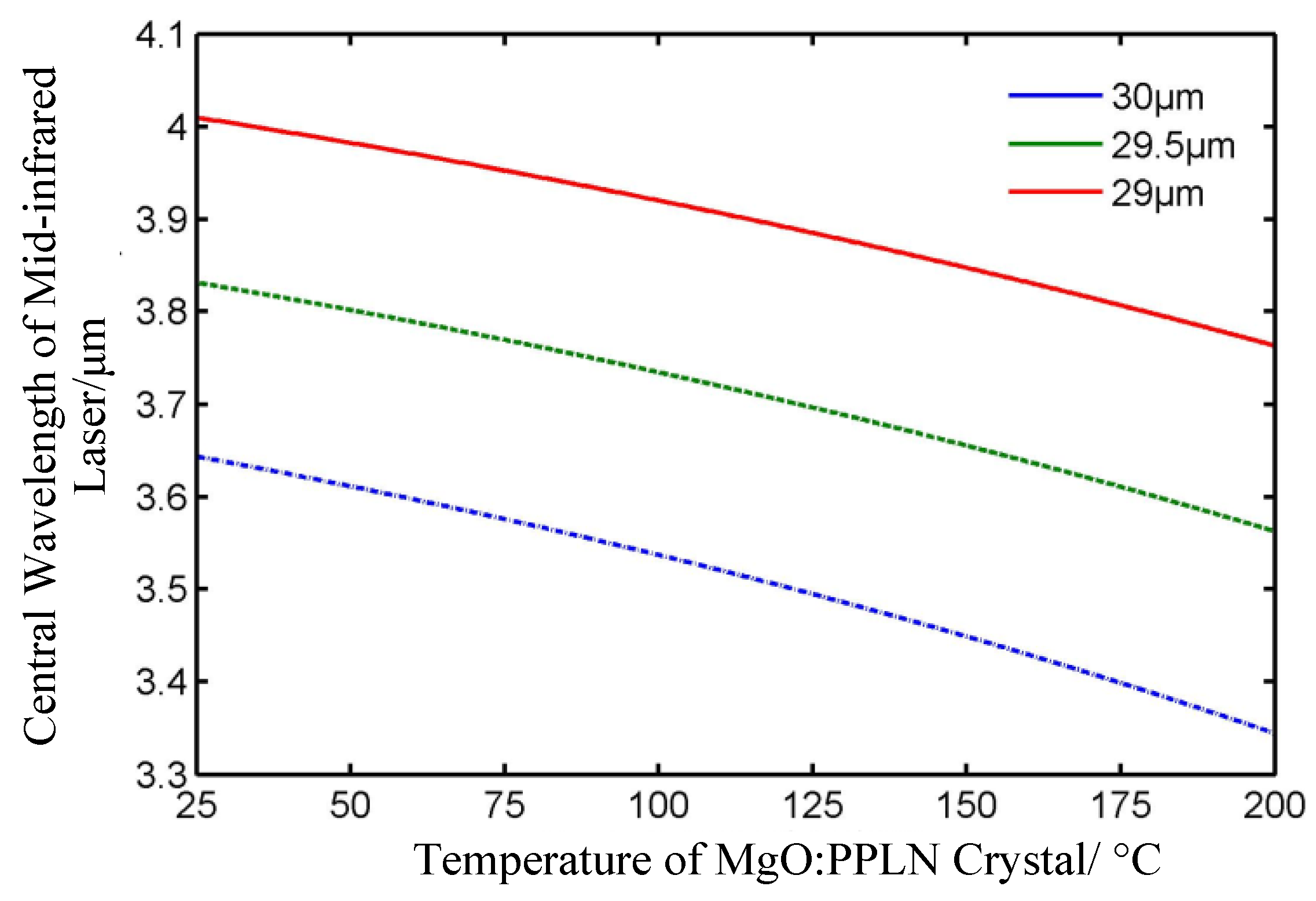
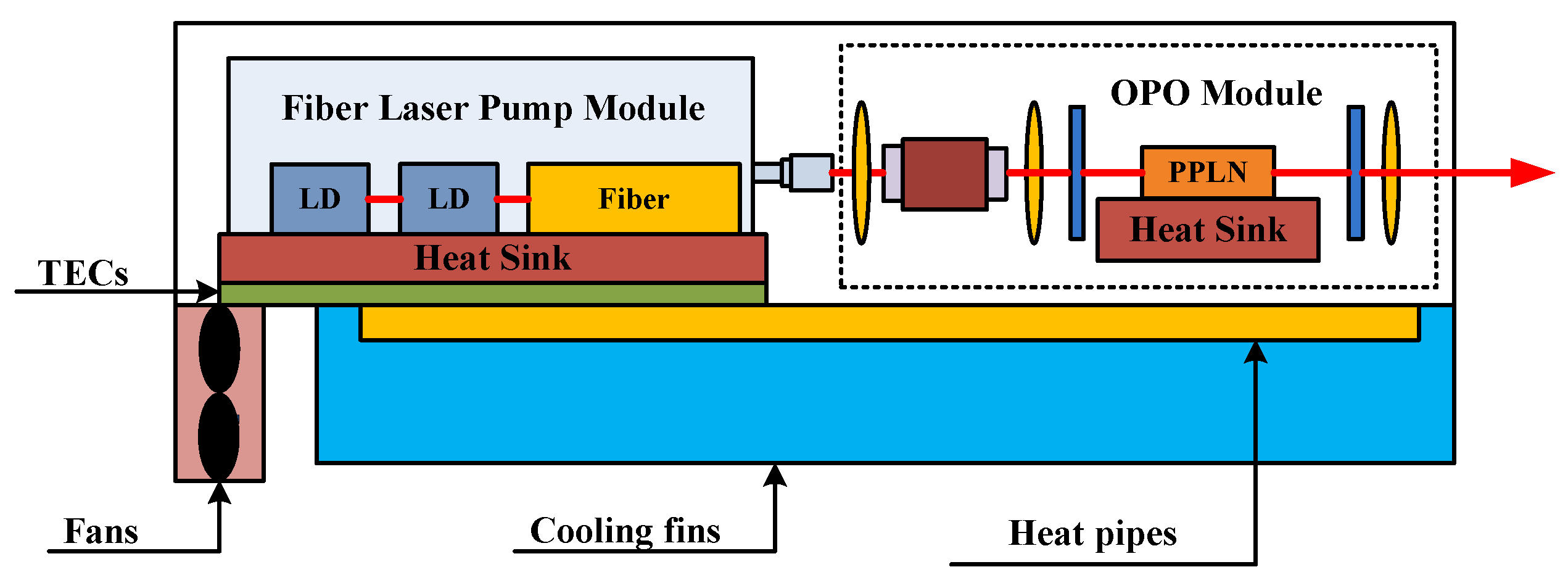
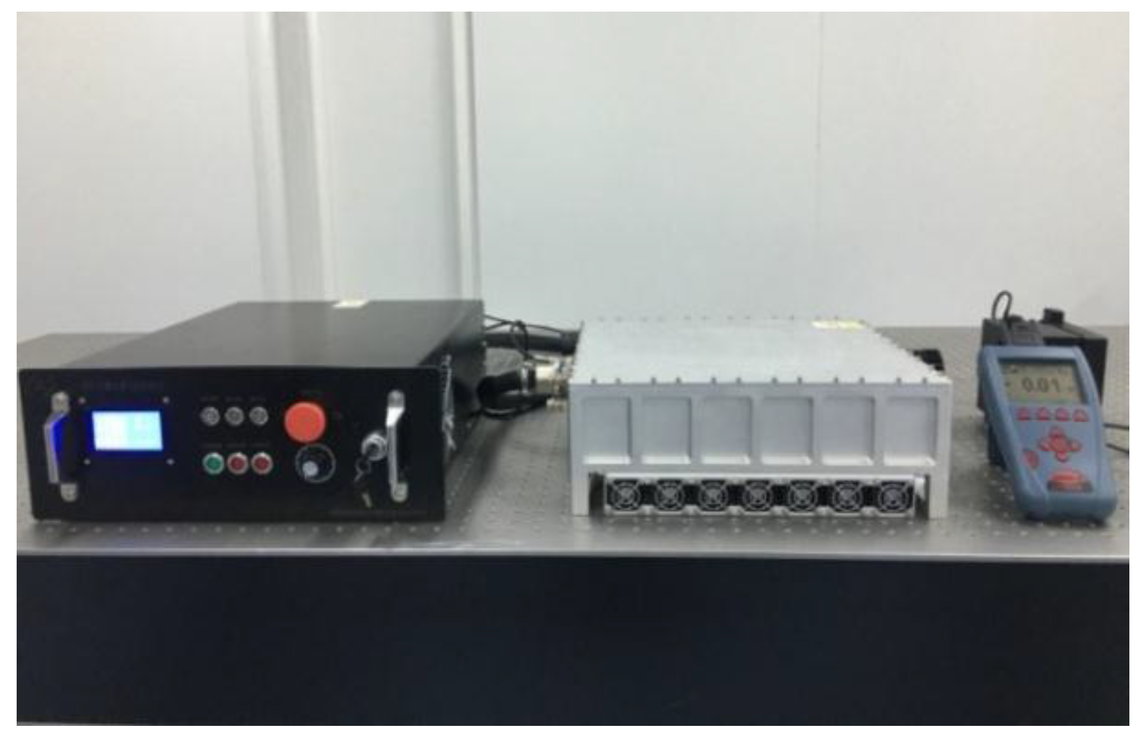
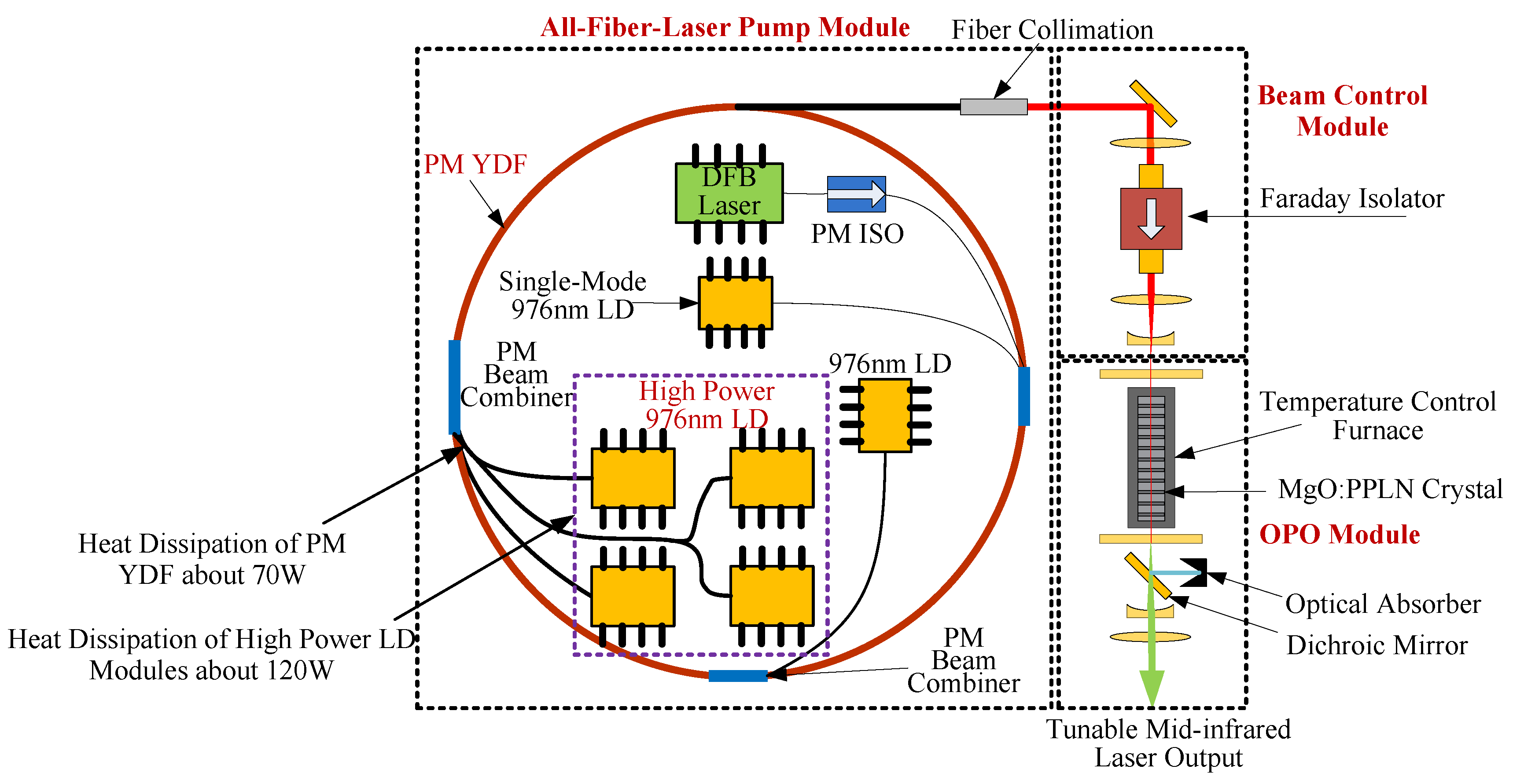
2.1. Design of a Tunable Mid-Infrared Solid-State Laser

The tunable mid-infrared solid-state laser that was investigated in the current study was an all-fiber laser pumped OPO, made up of an all-fiber laser pump module, beam control module and OPO module. The schematic diagram of the laser source is shown in Figure 1. The all-fiber laser pump module is based on the structure of the master oscillator power amplifier (MOPA), and includesmaster-oscillation and power-amplifier two parts. The master-oscillation stage uses a linearly polarized DFB laser to produce seed light at 1064 nm.The power-amplifier is made up of three-stages: linear, polarized and Yb doped fiber amplifier (YDFA) and can produce a 1064 nm laser at maximum output power of 50 W. The facula and polarization-state of the fiber pump laser are adjusted and isolated through a beam control module and then poured into OPO module on the MgO:PPLN crystal. The optical parametric oscillation process happens through the feedback effect of resonant cavity and obtains a near-infrared signal light and a mid-infrared idler. We used a dichroicmirror to filter out the signal light and finally achieved a mid-infrared laser at maximum output power of 5 W.
There is a certain relationship between the polarization period and temperature of MgO:PPLN crystal with the output wavelength of mid-infrared laser. The variation in the curve of the mid-infrared laser wavelength with the temperature of the crystal during polarization periods of 29 μm, 29.5 μm and 30 μm is shown in Figure 2. In our design, the wavelength of the mid-infrared laser was tuned by changing the temperature of the crystal. The MgO:PPLN crystal was fixed in the temperature control furnace, a film heater was used to control the temperature of the crystal and a PT1000 temperature sensor was used to measure the temperature of the crystal. We were able to obtain a certain wavelength from the mid-infrared laser by controlling the temperature of MgO:PPLN crystal at a specific value.

2.2. Design of the Thermal Control System

There were four high power 976 nm LD modules in the pump module and each had a maximum output power of 30 W. The electro-optic conversion efficiency of this LD module is about 50%; thus, the total heat generated from the LD modules was about 120 W. In addition, the maximum output power of the fiber laser pump module was over 50 W; thus, the maximum heat generated from the fiber was no more than 70 W. The total heat generated in the all-fiber laser pump module was no more than 200 W.
Each LD module was tightly fixed on the upper surface of a thin heat sink and fully contacted through grease. The fiber was encircled into a round shape and tightly pasted on the heat sink. The thin heat sink was made from molybdenum–copper material which has advantages of low density and high thermal conductivity. Thus, we were able to dissipate the waste heat generated from LD modules and fibers by cooling and keeping the upper surface temperature of the heat sink at a suitable value. A schematic diagram of the laser and thermal control system is shown in Figure 3.

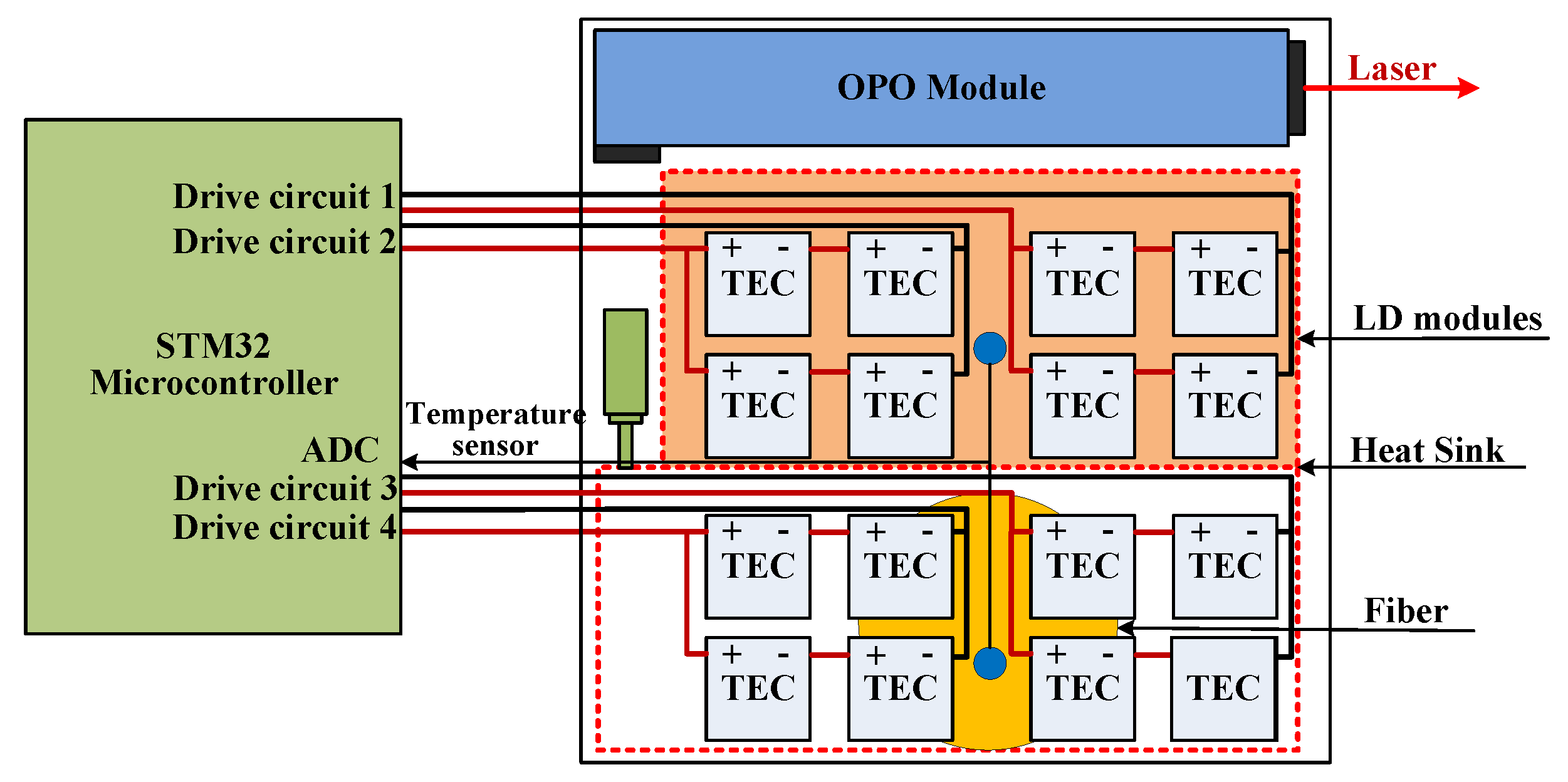
2.2.1. Constitution of the Thermal Control System

To achieve a better automatic cooling ability for the mid-infrared laser, the thermal control system was composed of an automatic temperature control circuit, TEMs, and an aluminum cabinet with cooling fins, axial fans and heat pipes. The heat sink was stuck to the cold side of TECs through grease and compressed tightly, allowing full contact and consequently, better heat transfer. The hot sides of the TECs were positioned close to the bottom of the cabinet. Thus, when the laser was working, the large amount of waste heat generated from the pump source module was absorbed by TECs and dissipated to the bottom of cabinet. The cooling fins were distributed outside the bottom of the cabinet to increase the heat transfer area. The axial fans were fixed on one side of the fins, increasing the heat convection coefficient through forced convection cooling. There were also two heat pipes fixed at the bottom of laser cabinet to improve heat transfer performance of the system.
The TEM used here was MCTE1-12712L-S, manufactured by Multicomp (Warsaw, Poland) with parameters shown in Table 1. There were 16 pieces of TECs divided into 4 groups to cool the heat sink. Each group was made up of 4 TECs with two pieces electrically connected in series and then electrically connected in parallel together. As shown in Figure 4 and Figure 5, two groups of TECs in a line were used to cool the LD modules and the remaining two groups were used to cool the fiber. This electrical connection and configuration mode improved the heat transfer efficiency by increasing the contact area and simplified the circuit structure through one output channel to drive 4 TECs. The axial fan used here was a pulse width modulation (PWM) speed controlled fan with 24 V direct current (DC) power supply. The max rated speed of this fan was 18,000 r/min and the maximum airflow was 0.011 m3/s. There were 7 fans parallel connected in a line to increase airflow.

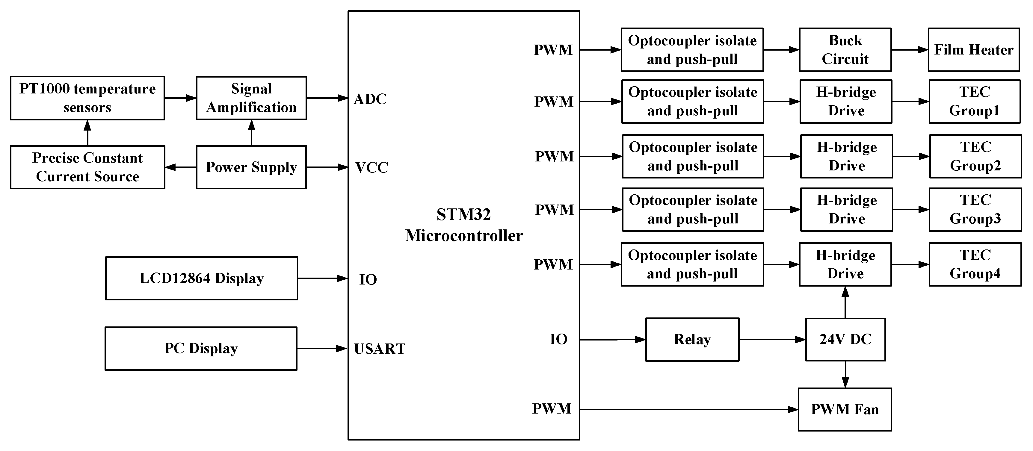
2.2.2. Hardware Circuit Design of the Thermal Control System

The main function of the system hardware circuit was to realize automated thermal control for the laser through exporting suitable drive power on the TECs. The diagram of the hardware circuit is shown in Figure 6. The circuit consisted of a STM32 microcontroller as control core, two PT1000 platinum resistor sensors to measure the upper surface temperature of heat sink, one PT1000 to measure the temperature of the MgO:PPLN crystal, an LCD12864 display to show the measuring temperature, setting temperature and operating state of the laser, a 24V DC power supply for the PWM fans, four H-bridges to drive the TECs, and a universal synchronous/asynchronous receiver/transmitter (USART) interface to communicate with a personal computer. The platinum resistor is a kind of temperature sensor with high stable performance and wide temperature measure ranging from −200 to +650 °C. The PT1000 temperature characteristics can be approximately expressed with the following equation:
R t = 1000 + 3.9 × t .
Rt is the resistance value (Ω) at temperature of t (°C). An 0.1 mA precise constant current source flows into the PT1000 resistor. The voltage on two sides of the resistor is amplified by an instrumentation amplifier INA128 before entering the analog-to-digital converter (ADC) interface on STM32. Then, the STM32 chip calculates the temperature value according to the conversion formula.

2.2.3. Software Design of the Thermal Control System

The software designed for the automated system was embedded in the STM32 microcontroller and programmed in C programming language based on a Keil development environment. It was made up of six function modules: a signal acquisition and process module for temperature measurement, an LCD12864 display module, a PID temperature control module, a PWM fan control module, a serial communicating module and a system monitoring and protecting module.
In the temperature control process, due to the time-varying, nonlinearity and uncertainty factors of the laser and external environment, the voltage exerted on the TEMs was calculated based on a parameter self-tuning incremental PID algorithm. The design of this PID algorithm is shown as below:
Δ U ( k ) = K p × [ e ( k ) e ( k 1 ) ] + K i × e ( k ) + K d [ e ( k ) 2 × e ( k 1 ) + e ( k ) ]
(1)
| e | > E a 1 : K p = K p 1 , K d = K d 2 , K i = 0 ;
(2)
E a 2 > | e | > E a 1 : K p = K p 2 , K d = K d 1 , K i = K i 2 ;
(3)
| e | < E a 2 : K p = K p 1 , K d = K d 1 , K i = K i 1 .
The relationships among the PID parameters are as follows: Kp1 > Kp2 >0, Kd1 > Kd2 > 0, Ki1 > Ki2 > 0, Ea1>Ea2>0. Kp1, Kp2, Kd1, Kd2, Ki1, Ki2, Ea1 and Ea2 are constants. When |e| is larger, we choose a larger Kp and smaller Kd to promote the tracking performance of the system, setting Ki = 0 to avoid larger overshoot when the system responds. When |e| is of medium size, we set smaller Kp and Ki values to decrease the system response overshoot. When |e| is smaller, we set larger Kp and Ki values to decrease the steady error and a medium-sized Kd to avoid system vibration near the set value.

3. Mathematical Model and Numerical Simulation

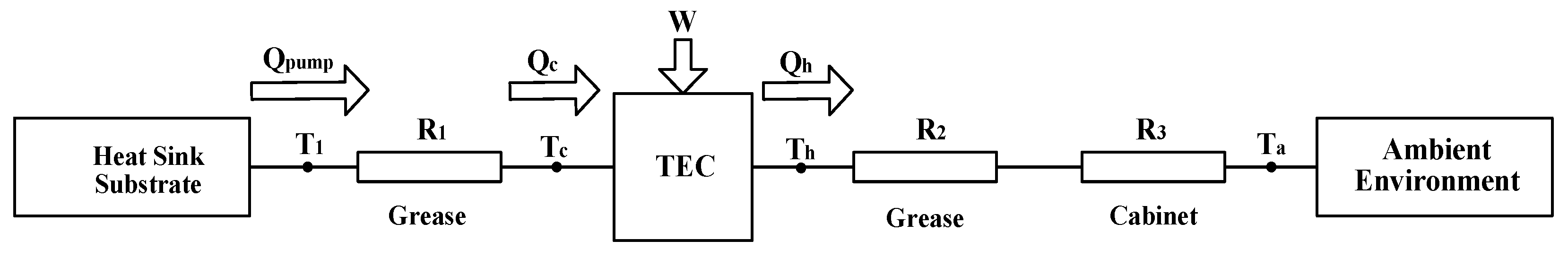
3.1. Thermal Analysis of TEM

The commercialized TEM is normally composed of a series of thermocouples electrically connected in series and thermally converged in parallel. When direct current flows through a thermocouple which is composed of an N semiconductor element and a P semiconductor element, the phenomenon of heat absorption and release happens at the contact surface. The current flows from the N element to the P element above the contact surface and the surface absorbs heat from the outside, becoming the cold side. The current flows from the P element to the N element below the contact surface and the surface releases heat to the outside, becoming the hot side [12]. The cooling capacity (Qc, heat absorption power on the cold side) of the TEM is
Q c = S m I T c 1 2 I 2 R m K m ( T h T c ) .
The quantity of heat production, Qh, on the hot side of the TEM is
Q h = S m I T h + 1 2 I 2 R m K m ( T h T c ) .
In Equations (3) and (4), Sm is the Seebeck coefficient of TEM, Tc is the temperature of the cold side of the TEM and Th is the temperature of the hot side of the TEM, I is the direct current through the module, Rm is the electrical resistance of the TEM and Km is the thermal conductance of the TEM.
The performance parameters, Sm, Rm and Km, can be figured out by the TEM parameters of Imax, ΔTmax, Th and Vmax given by the manufacturer through Equations (5)–(7) [19,20], of which Imax is the direct current flowing through TEM that causes the maximum temperature difference, ΔTmax. ΔTmax is the maximum temperature difference between the cold and hot sides of the TEM at a certain temperature, Th. Vmax is the direct voltage that diverges the ΔTmax.
R m = ( T h Δ T max ) × V max T h × I max
K m = ( T h Δ T max ) × V max × I max 2 × T h × Δ T max
S m = V max T h

3.2. Mathematical Model of the Thermal Control System

In order to estimate the performance of the thermal control system, a mathematical model of the system was established to calculate the cooling capacity. The thermal resistance network diagram is shown in Figure 7.
R1 is the thermal resistance of the thermally conductive grease between the substrate of the heat sink and the cold side of the TEMs. R2 is the thermal resistance of the thermally conductive grease between the hot side of the TEMs and the bottom inside of the cabinet. R1 is approximately equal to R2. R3 is the thermal resistance from the bottom inside of the cabinet to the ambient environment. T1 is the upper surface temperature of heat sink, since the 4 LD modules and fibers are closely fixed on the heat sink and they are the main heat sources. Thus, it is important to maintain T1 at a suitable and stable temperature to ensure the pump laser module works reliably. Tc is the cold side temperature of the TEMs, Th is the hot side temperature of TEMs and Ta is the temperature of the ambient environment. Qpump is the heat generated by the pump laser module and Qc is the cooling capacity of the TEM, since there are 16 pieces of TECs used in the system, and assuming each TEC hasthe same Qc, it can be deduced that the equation at the steady heat transfer state is
Q p u m p = 16 × Q c .
The one-dimensional steady heat transfer equation of the thermal resistance, R1, can be carried out by thermal analysis as shown below:
Q c = T 1 T c R 1 .
Qh is the heat release output at the hot side of TEM. Thus, we can determine the one-dimensional steady heat transfer equation:
Q h = T h T a R 2 + R 3 .
From thermodynamic Equations (3), (4) and (8)–(10), the TEC cooling capacity (Qc) can be written as the following expression:
Q c ( T 1 , T a , I ) = [ S m 2 I 2 ( R 2 + R 3 ) S m I K m ] T 1 + K m T a + 1 2 I 2 R m [ ( 2 K m S m I ) ( R 2 + R 3 ) + 1 ] [ S m I ( R 2 + R 3 ) 1 ] ( S m I R 1 + 1 ) K m ( R 1 + R 2 + R 3 ) .
From Equation (11), it can be deduced that Qc mainly depends on the TEM performance parameters: Sm, Rm, Km, TEC drive current I, the system thermal resistances (R1, R2 andR3), the upper surface temperature of the heat sink (T1) and the ambient environment temperature (Ta). If it is assumed that T1 is 293.15 K at which the pump laser module could work steadily and normally, I and Ta are set to regular values, and Sm, Rm and Km are calculated according to the TEM parameters of Imax, ΔTmax, Th and Vmax (which are given by the manufacturer), then we just need to know the system’s thermal resistances (R1, R2 and R3) to calculate Qc. If Qc multiplied by 16 is greater than Qpump, we can make the conclusion that the pump laser module can work at a suitable and stable temperature. The temperature of heat sink T1 can also be written as the following expression:
T 1 ( Q c , T a , I ) = { [ S m I ( R 2 + R 3 ) 1 ] ( S m I R 1 + 1 ) K m ( R 1 + R 2 + R 3 ) } Q c K m T a 1 2 I 2 R m [ ( 2 K m S m I ) ( R 2 + R 3 ) + 1 ] S m 2 I 2 ( R 2 + R 3 ) S m I K m .
If assuming Equation (8) is established and Qpump is at its maximum value, then we can obtain Qc as a fixed constant, setting I and Ta at regular values, and calculate Sm, Rm and Km, allowing the temperature (T1) to be calculated out by the expression. Finally, it can be concluded whether the pump laser module is working at a suitable temperature by comparing T1 with the normal operating temperature range.

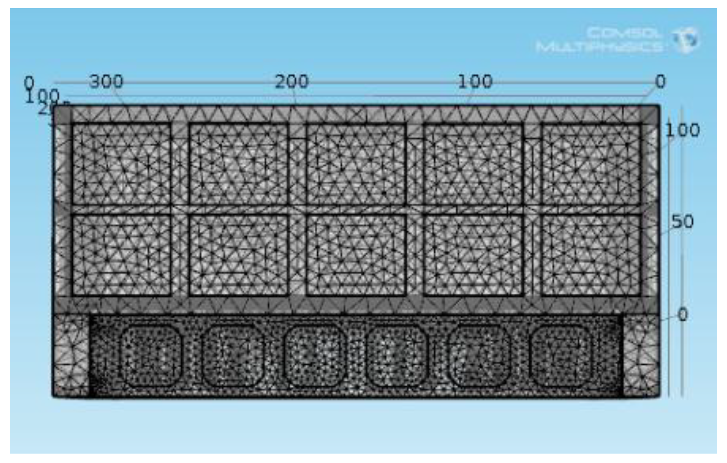
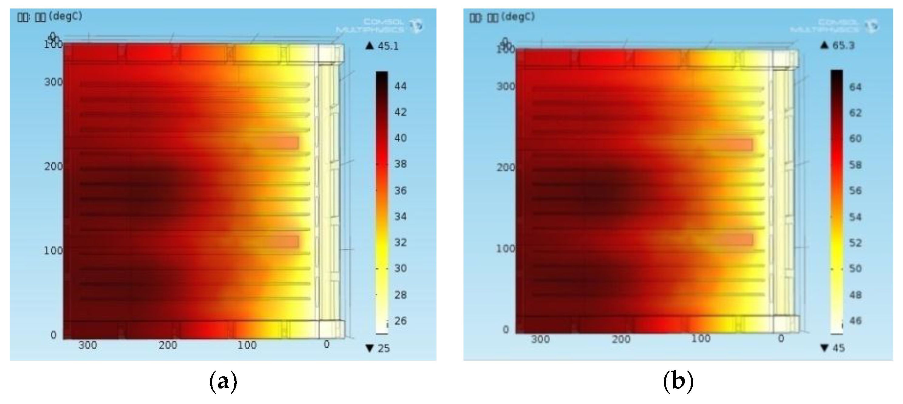
3.3. Numerical Simulation

A finite-element model was established using COMSOL 4.4 software to estimate the cooling capacity of the thermal control system, and the thermal transfer process was mainly analyzed to simulate the temperature rise and the thermal distribution in the laser cabinet. The heat dissipation of the mid-infrared OPO laser is a multi-physics field coupled process with heat conduction, heat convection and gas turbulent flow.
The material properties and size of the finite-element model are shown in Table 2. The whole laser cabinet structure including fins was made by aluminum material. The aluminum 6063-T83 with thermal conductivity 201 W/(m·K) was defined as the cabinet material in the software. When the thermal control system works, the cold side of the TEMs absorbs the heat produced by the pump laser module, and releases heat at the hot side simultaneously. This heat quantity was taken as the heat source in the model and delivered through thermal conduction to the laser cabinet. A 500 W boundary heat source was defined to simulate the quantity of heat produced by the TEMs. There were 14 cooling fins at the bottom of the laser cabinet. The shape of each fin was 300 × 50 × 2 mm3, and the fin spacing was 20 mm. Seven fans were defined in the software, and the flow rate was set at 0.011 m3/s. The thermal conductivity of the heat pipe was set in segmented mode to make a closer equivalent simulation of its physical features. The thermal conductivity of the evaporation section was set at 2 × 10⁴ W/(m·K), while the thermal conductivity of the condensation section was set at 500 W/(m·K).
The finite-element mesh model is shown in Figure 8 and the size unit of this model is in millimeters, the results for the temperature analysis of the model at ambient environment temperatures of 25 degrees and 45 degrees are shown in Figure 9, and the temperature units are degrees. It can be deduced that the highest temperature rise occurred at the left edge of the laser cabinet and with almost the same value at the different ambient temperatures. It is assumed that the two groups of TEMs were close to the left edge of the cabinet with the highest temperature at the hot side, since the simulated heat source was 500 W and the temperature rise was almost 20 K, thus the thermal resistance (R3) for the TEMs was 0.04 K/W. The other two groups of TEMs in the middle of the cabinet almost had a 15 K temperature rise at the hot side and the thermal resistance (R3) for them was 0.03 K/W.
The cooling capacity of the system is discussed in two situations—at 25 °C (room temperature) and 45 °C (high temperature). From the temperature rising simulation results in Figure 9, we approximately calculated the TEC performance parameters, Rm, Km and Sm, for Th = 50 °C and the following parameters were obtained: Rm = 0.985 Ω, Km = 0.946 K/W and Sm = 0.048 V/K. Using Equation (11), in the first situation, Ta = 298.15 K (25 °C), the TEC drive current (I) was defined as 5A, and it was assumed that R1 = R2 = 0.1 K/W and T1 = 293.15 K (20 °C) at which the pump source can work stably. For the two groups of TEMs with R3 = 0.04 K/W, the cooling output of each TEM was Qc1 = 39.5 W, and for the other two groups of TEMs with R3 = 0.03 K/W, the cooling output of each TEM was Qc2 = 40 W. Consequently, the total cooling output (Qc) of the 16 TEMs was about 636 W.
When Ta = 318.15 K (45 °C) with the same other parameters, the two groups of TEMs with R3 = 0.04 K/W had Qc1 = 24 W, and the other two groups of TEMs with R3 = 0.03 K/W had Qc2 = 24.4 W. Thus, the total cooling output (Qc) of the 16 TEMs was about 387.2 W. The calculated results indicate that the temperature of the LD modules and the fiber in the pump source can be controlled at the setting value in the ambient temperatures of 25 °C and 45 °C. The estimated cooling capacity of the system in different ambient environments is shown in Table 3.

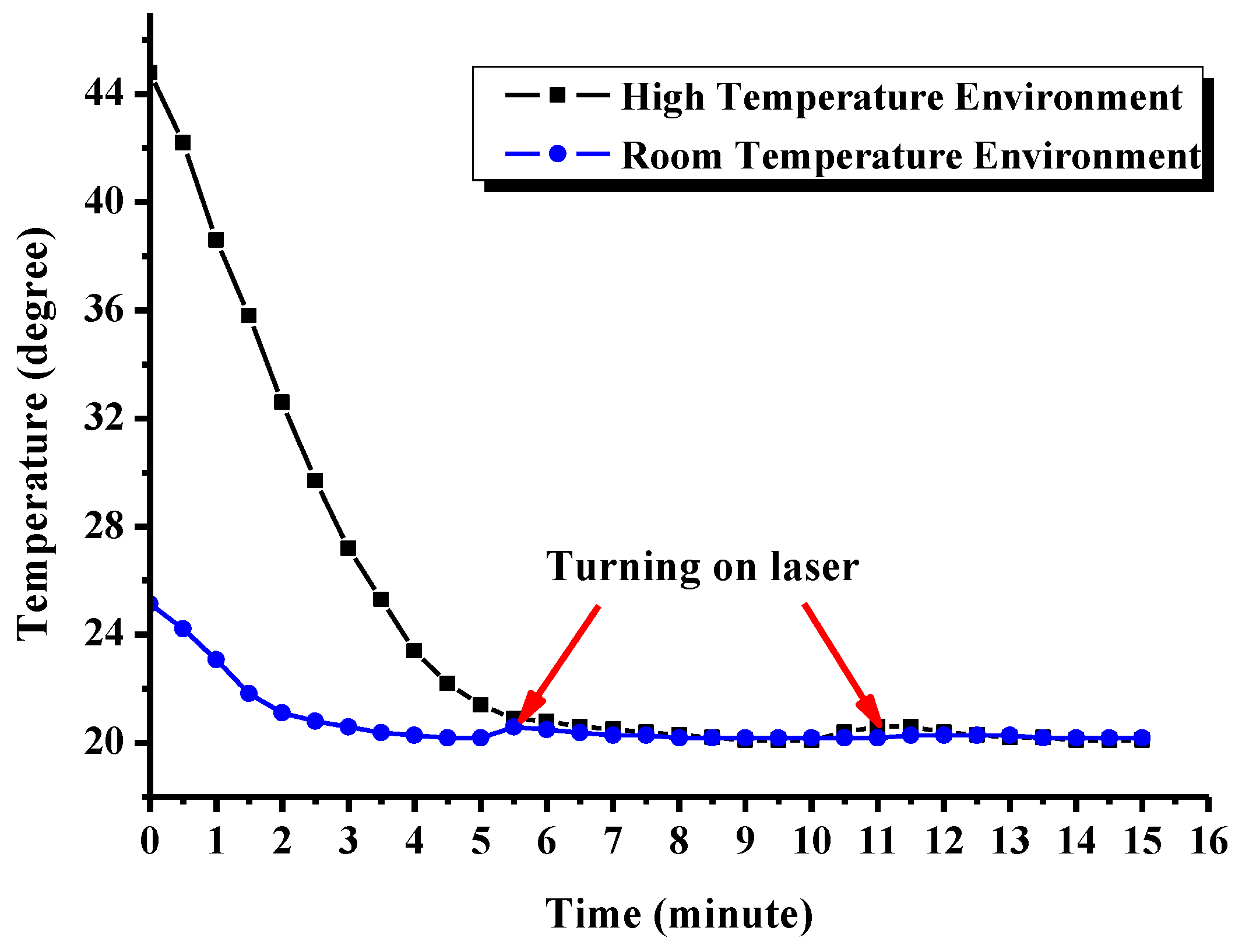
4. Experiment Results and Discussion

Experiments in room and high temperature environments were conducted to verify the actual cooling capacity of the thermal control system and the performance of the mid-infrared OPO laser. The output power of OPO laser was measured using the laser power meter in 25 °C and 45 °C temperature environments. The laser controlling temperature was set to 20 °C. The near-field pattern of the laser was analyzed through the laser beam quality analyzer (PY3) in room temperature. The picture of the mid-infrared OPO laser is shown in Figure 10. The black case on the left side is the electrical control unit, and the case with fans on the right side is the optical unit.
In the room temperature environment, when the electrical control unit was powered on, the thermal control system began to control the refrigeration of the TEMs to reduce the temperature of the laser. About 4 min later, the upper surface temperature of heat sink was reduced and stabilized at about 20.1 °C. Then the pump source was turned on and the laser began to output light. Since the pump source generated heat and transferred it to the heat sink, the temperature rose to about 20.6 °C. The temperature control circuit acquired rose in temperature and calculated the PWM control variable based on the PID algorithm. Then the output voltage exerted on TEMs was increased appropriately and the cooling output was amplified. About 1 min later, the temperature was reduced and stabilized at about 20.1 °C. The temperature variation of the pump laser over time is shown in Figure 11.
In the high temperature experiment, the mid-infrared OPO laser was put in the high and low temperature test boxes, as shown in Figure 12, and the environment temperature was set to 45 °C. About 10 min after the electrical control unit was powered on, the temperature was reduced and stabilized at about 20.1 °C. Then, the pump source was turned on and the laser began to output light, and the temperature rose to about 20.7 °C. About 1 min later, the temperature was reduced and stabilized at about 20.1 °C, as shown in Figure 11.
The output power variation of the mid-infrared OPO laser with 70% maximum pump power in room and high temperature environments is shown in Figure 13. The near-field pattern of the OPO laser at room temperature was also measured and is shown in Figure 13. The following formula was used to calculate the output power stability (S) of the OPO laser:
S = ± P max P min 2 × P a v r .
Pmax, Pmin and Pavr are the maximum, minimum and average output powers of the OPO laser with the measured values. The calculated output power stability values of the laser in room and high temperature environment were ±0.7% and ±1%, respectively. The one-hour output power stability of the laser in room temperature environment was within ±1%. The experimental results above show that the thermal control system has a strong cooling capacity to keep the substrate temperature of the pump laser module at the setting value.The laser was able to work normally in both the room and high temperature environments, and when pump power of the laser changed, the temperature control circuit was able to adjust the output drive voltage on TEMs according to the measured temperature value, keeping the temperature of the pump laser at a stable and suitable value.

5. Conclusions

In this paper, a tunable all-fiber laser pumped OPO was established, and a thermal control system based on TEMs, automatic temperature control circuit, PID algorithm, cooling fins, fans and heat pipes was integrated and designed for the laser. This system is compact, light, air-cooling and has automatic temperature control. A finite-element model of the cooling system was built and simulated in the COMSOL 4.4 software to analyze the thermal transfer process. A mathematical model and method were established to estimate the cooling capacity of the system under different ambient environments. The estimated maximum cooling capacity of this system was approximately 636W in 25 °C and 387 W in 45 °C. The substrate temperature of the pump laser module was able to be maintained at a stable value with a steady state error of no more than 0.2 °C in room and high temperatures when the OPO laser was working. The output power stability of the OPO laser in room and high temperatures were ±0.7% and ±1% respectively. The experimental results indicate that this compact air-cooling thermal control system can effectively solve the heat dissipation problem of mid-infrared solid-state lasers with a one hundred watts level pump module in room and high temperature environments.

Author Contributions

F.C., Y.H. and D.Y. conceived, designed and performed the experiment; Y.H. and Q.P. contributed the all-fiber laser pump module design and the OPO module design, K.Z. established the finite-element model of the cooling system, D.Y. contributed to the thermal control system design and wrote the paper, F.C. and L.G. supervised the whole work.

Acknowledgments

The authors acknowledge the financial support of the Open Fund Project of the State Key Laboratory of Laser and Material Interaction (No. SKLLIM1713), the National Natural Science Foundation of China (61705219), the National Defense Science and Technology Innovation Fund of the Chinese Academy of Sciences (No. CXJJ-16M228), the Major Science and Technology Biding Project of Jilin Province (No.20160203016GX), the Young and Middle-Aged Science and Technology Innovation Leader and Team Project of Jilin Province (No. 20170519012JH), and the Youth Innovation Promotion Association of CAS.

Conflicts of Interest

The authors declare no conflict of interest.

References

  1. Jin, Y.W.; Cristescu, S.M.; Harren, F.J.; Mandon, J. Two-crystal mid-infrared optical parametric oscillator for absorption and dispersion dual-comb spectroscopy. Opt. Lett. 2014, 39, 3270–3273. [Google Scholar] [CrossRef] [PubMed]
  2. Liu, J.; Tang, P.H.; Chen, Y.; Zhao, C.J.; Shen, D.Y.; Wen, S.C.; Fan, D.Y. Highly efficient tunable mid-infrared optical parametric oscillator pumped by a wavelength locked, Q-switched Er:YAG laser. Opt. Express. 2015, 23, 20812–20819. [Google Scholar] [CrossRef] [PubMed]
  3. Steinle, T.; Kumar, V.; Floess, M.; Steinmann, A.; Marangoni, M.; Koch, C.; Wege, C.; Gerullo, G.; Giessen, H. Synchronization-free all-solid-state laser system for stimulated Raman scattering microscopy. Light Sci. Appl. 2016, 5, e16149. [Google Scholar] [CrossRef]
  4. Yan, M.; Luo, P.L.; Iwakuni, K.; Millot, G.; Hansch, T.W.; Picque, N. Mid-infrared dual-comb spectroscopy with electro-optic modulators. Light Sci. Appl. 2017, 6, e17076. [Google Scholar] [CrossRef]
  5. Darvish, G.; Moravvej-Farshi, M.K.; Zarifkar, A.; Saghafi, K. Pre-compensation techniques to suppress the thermally induced wavelength drift in tunable DBR lasers. IEEE J. Quantum Electron. 2008, 44, 958–965. [Google Scholar] [CrossRef]
  6. Andreoni, E.; Xu, J.H.; Cartaleva, S.; Celli, R.M.; Mango, F.; Gozzini, S. A simple system of thermal control and frequency stabilization of solitary diode lasers. Rev. Sci. Instrum. 2000, 71, 3648–3652. [Google Scholar] [CrossRef]
  7. Datta, M.; Choi, H.W. Microheat exchanger for cooling high power laser diodes. Appl. Therm. Eng. 2015, 90, 266–273. [Google Scholar] [CrossRef]
  8. Shu, S.L.; Hou, G.Y.; Wang, L.J.; Tian, S.C.; Vassiliev, L.L.; Tong, C.Z. Heat dissipation in high-power semiconductor lasers with heat pipe cooling system. J. Mech. Sci. Technol. 2017, 31, 2607–2612. [Google Scholar] [CrossRef]
  9. Jia, G.N.; Qiu, Y.T.; Yan, A.R.; Yao, S.; Wang, Z.Y. Laser three-dimensional printing microchannel heat sink for high-power diode laser array. Opt. Eng. 2016, 55, 096105. [Google Scholar] [CrossRef]
  10. Mu, J.; Feng, G.J.; Yang, H.M.; Zhang, H.; Zhou, S.H. Research on multiannular channel liquid cooling method for thin disk laser. Opt. Eng. 2014, 53, 056110. [Google Scholar] [CrossRef]
  11. Zhang, W.; Shen, L.M.; Yang, Y.X.; Chen, H.X. Thermal management for a micro semiconductor laser based on thermoelectric cooling. Appl. Therm. Eng. 2015, 90, 664–673. [Google Scholar] [CrossRef]
  12. Zhao, D.L.; Tan, G. A review of thermoelectric cooling: Materials, modeling and applications. Appl. Therm. Eng. 2014, 66, 15–24. [Google Scholar] [CrossRef]
  13. Li, C.; Jiao, D.; Jia, J.Z.; Guo, F.; Wang, J. Thermoelectric cooling for power electronics circuits: Modeling and active temperature control. IEEE Trans. Ind. Appl. 2014, 50, 3995–4005. [Google Scholar] [CrossRef]
  14. Li, J.H.; Zhang, X.R.; Zhou, C.; Zheng, J.G.; Ge, D.S.; Zhu, W.H. New application of an automated system for high-power LEDs. IEEE/ASME Trans. Mechatron. 2016, 21, 1035–1042. [Google Scholar] [CrossRef]
  15. Noguchi, N.; Okuchi, T. A peltiercooling diamond anvil cell for low-temperature Raman spectroscopic measurements. Rev. Sci. Instrum. 2016, 87, 125107. [Google Scholar] [CrossRef] [PubMed]
  16. Dong, J.; Liu, X.S.; Peng, C.; Liu, Y.Q.; Wang, Z.Y. High Power Diode-Side-Pumped Q-Switch Nd:YAG Solid-State Laser with a Thermoelectric Cooler. Appl. Sci. 2015, 5, 1837–1845. [Google Scholar] [CrossRef]
  17. Wang, H.; Yu, Y.L. Dynamic modeling of PID temperature controller in a tunable laser module and wavelength transients of the controlled laser. IEEE J. Quantum Electron. 2012, 48, 1424–1431. [Google Scholar] [CrossRef]
  18. Shen, L.M.; Chen, H.X.; Xiao, F.; Yang, Y.X.; Wang, S.W. The step-change cooling performance of miniature thermoelectric module for pulse laser. Energy Convers. Manag. 2014, 80, 39–45. [Google Scholar] [CrossRef]
  19. Lineykin, S.; Ben-Yaakov, S. Analysis of thermoelectric coolers by a spice-compatible equivalent-circuit model. IEEE Power Electron. Lett. 2005, 3, 63–66. [Google Scholar] [CrossRef]
  20. Lineykin, S.; Ben-Yaakov, S. Modeling and analysis of thermoelectric modules. IEEE Trans. Ind. Appl. 2007, 43, 505–512. [Google Scholar] [CrossRef]
Figure 1. The schematic diagram of the designed tunable all-fiber laser pumped optical parametric oscillator (OPO).
Applsci 08 00878 g001
Figure 2. The variation in the curve of the laser wavelength with changes in the temperature of the crystal at different polarization periods.
Applsci 08 00878 g002
Figure 3. Schematic diagram of the laser and thermal control system.
Applsci 08 00878 g003
Figure 4. Diagrammatic sketch of the thermoelectric cooler (TEC) layout.
Applsci 08 00878 g004
Figure 5. Picture of TEC layout.
Applsci 08 00878 g005
Figure 6. Diagram of the hardware circuit.
Applsci 08 00878 g006
Figure 7. The thermal resistance network diagram.
Applsci 08 00878 g007
Figure 8. Finite-element mesh model of the system.
Applsci 08 00878 g008
Figure 9. Finite-element analysis results: (a) in 25 degrees and (b) in 45 degrees.
Applsci 08 00878 g009
Figure 10. Picture of the mid-infrared OPO laser.
Applsci 08 00878 g010
Figure 11. Temperature variation of the pump laser.
Applsci 08 00878 g011
Figure 12. Experiment in the high temperature environment.
Applsci 08 00878 g012
Figure 13. Output power variation and near-field pattern of the OPO laser.
Applsci 08 00878 g013
Table 1. TEC parameters.
Parameters
Internal resistance1 Ω ±10%
Imax12 A
Vmax15.4 V
-Th = 27 °CTh = 50 °C
Qmax110 W134 W
ΔTmax68 °C75 °C
Solder melting point138 °C
Table 2. Material properties and sizesin the finite-element model.
MaterialThermal Conductivity (W/m·K)SizeNumberFlow Rate (m3/s)
CabinetAluminum 6063-T83201330 × 330 × 115 mm3
(L × W × H)
Wall thickness: 10mm
//
FinAluminum 6063-T83201300 × 50 mm2 (L × W)
Fin thickness: 2mm
Fin spacing: 20mm
14/
Heat pipe/Evaporation section:2 × 10⁴
Condensation section: 500
280 × 12 × 5 mm3
(L × W × H)
2/
Fan//40 × 40 × 10 mm360.011
Table 3. The estimated cooling capacity of the system in different ambient environments.
Ambient Environment Temperature (Ta)T1TEC Driving CurrentPosition of TEMsR3TEM Cooling Output (Qc1)System Cooling Capacity (Qc)
298.15 K (25 °C)293.15 K (20 °C)5 ATEMs near the edge0.04 K/W39.5 W636 W
TEMs in the middle0.03 K/W40 W
318.15 K (45 °C)293.15 K (20 °C)5 ATEMs near the edge0.04 K/W24 K/W387.2 W
TEMs in the middle0.03 K/W24.4 W

