Abstract
In order to explore the moduli decay patterns of asphalt mixtures under different loading conditions, the nonlinear fatigue damage model was implemented in order to simulate the moduli decay patterns. Then, the direct tensile, indirect tensile, and uniaxial compression fatigue tests were employed under four kinds of stress levels with four parallel tests. The specimens of AC-13C Styrene-butadiene-styrene (SBS) modified mixtures were manufactured. Based on the test results, the decay patterns of the moduli during fatigue tests under different stress states were revealed, and the parameters of the damage model under different test conditions were obtained. By changing the values of the model parameters under a certain loading condition, fatigue curves were obtained. Then, the fatigue properties of asphalt mixtures under different stress states could be compared and analyzed directly. The result indicated that the evolution curves of fatigue damage for the direct tensile test, the indirect tensile test, and the uniaxial compression test all experienced three stages, which indicates that the fatigue damage characteristic of asphalt mixtures is non-linear. The decay patterns of the direct tensile moduli and the tensile moduli measured by the indirect tensile test are similar. The decay patterns of the uniaxial compression and the compression moduli measured by indirect tensile test are similar. The decay patterns of tensile and compressive moduli are obviously different. At the same cycle ratio state, the position of the decay curve for the compression moduli is higher than that of the tensile moduli. It indicates that the tensile failure is the main reason of the fatigue damage for asphalt mixture. The new analysis method of fatigue damage was proposed, which provides a possibility to compare the fatigue results that were obtained from different loading conditions and different specimen sizes.
Keywords:
asphalt mixture; service life; fatigue test; moduli decay; loading condition; stress state 1. Introduction
Fatigue cracking is one of the most common distresses in asphalt pavement [1,2,3]. Fatigue cracking of asphalt pavement is an important consideration in asphalt mixture design and the structural design of flexible pavements [4,5]. Fatigue life design and maintenance strategies employ a challenging task due to the inherent nonlinear viscoelastic properties of asphalt mixtures and the complex cracking behavior observed in the field [6,7,8,9,10]. The damage appeared and accumulated gradually during the service life of asphalt pavement [11]. Under the action of cyclical traffic loads, the damage will increase and the pavement would suffer from the fatigue failure. Therefore, the service life of asphalt pavement would be decreased. More and more studies of fatigue performance for asphalt mixtures under the traffic and environmental conditions have been conducted [12,13]. In order to ensure the durability and usability of asphalt pavement, many researchers have been conducting the works of evaluation of fatigue characteristics via varied fatigue test methods in different specimen’s size and different stress levels.
Xie Jun suggested that the direct tension strength got larger at higher strain loading rate [14]. Hyung Suk Lee conducted an indirect tensile test and determined the fundamental viscoelastic material property, which means that the strength of asphalt mixture were related to the temperature and loading time [15]. Waleed A. Zeiada employed the uniaxial compression test and observed that the fatigue endurance limit value increases by the increasing of temperature, asphalt content, and rest periods, whereas it decreased when the volume of air voids increases [16]. Different test methods produce different results. So far, three traditional test methods have been employed extensively: the direct tensile test, the indirect tensile test, and the uniaxial compression test. The direct tensile test refers to the test of a material under the action of a uniaxial tensile load. Under the assumption of homogeneity, the stress level or the stress ratio is same on each cross-section of the specimen during the test process, so the fracture position will appear at the weakest cross-section. The failure will occur for the accumulation of the micro-cracks [14]. The indirect tensile test (IDT, also called splitting test) is in a two-dimensional stress state. The lateral direction lies in the tension state, while the longitudinal direction lies in the compression one. It can simulate the stress state of asphalt pavement under traffic loads. The tensile stress near the crack area of the IDT specimen is uniform relatively [17]. The uniaxial compression test is also a one-dimensional stress test method. During the process of the uniaxial compression test, the stress level and the stress ratio are same on each cross-section of the specimen. The stress state on each cross-section is the one-dimensional compression stress state [18].
Fatigue test results of asphalt mixtures are sensitive to different test conditions. Different test methods will have the different loading conditions, which will lead to the different stress states for the specimen of asphalt mixtures. For each test method, the test results of fatigue are not correlated and are inconsistent with others. Moreover, the difference of fatigue test results is still relatively large. Therefore, even to the same material, the fatigue properties from the different test methods cannot be compared. So far, it cannot form a unified evaluation and comparison method among different fatigue test results of asphalt mixtures. Furthermore, the fatigue tests of asphalt mixtures are sensitive to the test types and size of the specimens [19,20].
The main purpose of this paper is to reveal the decay patterns of different modulus for asphalt mixture in fatigue test, which can be employed to improve the design accuracy of asphalt pavement.
2. Materials Preparation and Test Method
2.1. Materials
The main materials of the tests were the Styrene-butadiene-styrene(SBS) modified asphalt and the limestone aggregate. The AC-13 dense graded asphalt mixture was employed. The test results of asphalt are shown in Table 1. The test results of limestone aggregate are shown in Table 2. The gradation curve of dense graded asphalt mixture is shown Figure 1.

Table 1.
Test result of Styrene-butadiene-styrene (SBS) modified asphalt.

Table 2.
Physical property of aggregates.
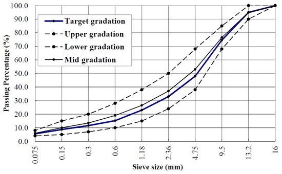
Figure 1.
Gradation curve of dense graded asphalt mixture (AC-13).
The optimum asphalt-aggregate ratio was 5.2%, which was obtained by the Marshall Tests, and the test results are shown in Table 3.

Table 3.
Marshall Test results at optimal asphalt content.
2.2. Specimens Preparation
According to the Chinese Standard Test Methods of Asphalt and Asphalts Mixtures for Highway Engineering (JTG E20-2011) [23], the block samples of 400 mm × 300 mm × 50 mm were fabricated through the equipment of vibrating compaction. Then, the beam specimens were cut from block samples into the size of 250 mm × 50 mm × 50 mm for the direct tensile tests, as shown in Figure 2a. During the uniaxial compression test, the Superpave Gyratory Compactor (SGC) was employed, which can control the volume of air voids of asphalt mixture more accurately. The previous studies [24,25] showed that the stress concentration would be occurred when the height is less than 50 mm. The specimens for uniaxial compression test were manufactured with 100 mm in height and 100 mm in diameter, which was shown in Figure 2b, and the indirect tensile specimens were prepared by cutting the top and the bottom surface of the specimens of uniaxial compression test to the size of 100 mm in height and 60 mm in diameter, which was shown in Figure 2c. All of the specimens were put in an environment chamber at 15 °C for 24 h before the tests. There were four parallel tests for each type of test.
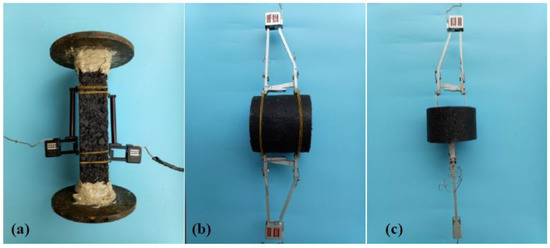
Figure 2.
(a) Direct tensile test specimen; (b) Uniaxial compression specimen; and, (c) Indirect tensile specimen.
2.3. Test Method
In this paper, some influencing factors were considered for the fatigue test. The external factors, such as stress ratio, test temperature, loading frequency, and loading waveform were considered in the fatigue test. The internal factors, such as the fatigue test method, asphalt varieties, asphalt content, mineral type, mixture gradation, porosity, etc. were considered in the mix design. The specific test conditions are shown in Table 4.

Table 4.
Influencing factors of fatigue test and the levels of each factor.
The process of the three kinds of fatigue tests is shown in Figure 3.
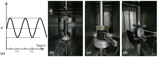
Figure 3.
(a) Load waveform of fatigue test; (b) Direct tensile test; (c) Uniaxial compression test; and, (d) Indirect tensile test.
3. Test Result and Analysis
The fatigue test results of the direct tensile, the uniaxial compression, and the indirect tensile were shown in Table 5, Table 6 and Table 7, respectively.

Table 5.
Test result of direct tensile.

Table 6.
Test result of uniaxial compression.

Table 7.
Test result of indirect tensile.
3.1. The Establishment of the Decay Model for Moduli
The conventional S-N fatigue Equation is widely used to analyze the fatigue performance of asphalt mixtures [26,27]. Chaboche [28] defined the traditional S-N fatigue Equation as:
or
where, Nf is fatigue life, t is stress ratio, σ is stress level. K, and n are the material parameters of asphalt mixtures.
According to Equations (1) and (2), the fatigue curves characterized by stress ratios and stress levels were shown in Figure 4a,b, respectively.
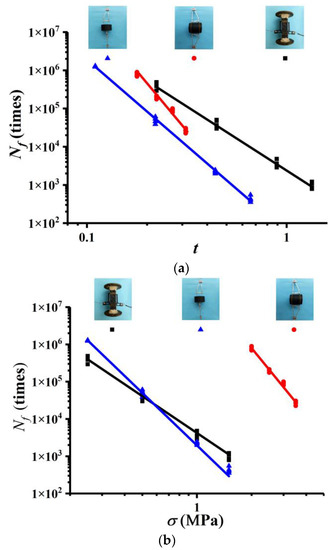
Figure 4.
(a) Fatigue curves characterized by stress ratio (b) Fatigue curves characterized by stress level.
From Figure 4, it can be observed that the S-N fatigue curves of asphalt mixtures show great difference under different stress conditions. It is difficult to evaluate the fatigue performance of asphalt mixtures in different test methods [7]. Given that, in this paper, the nonlinear fatigue damage model was implemented to simulate the moduli decay patterns. Defining the moduli as the damage variable, the damage model based on the moduli decay was established.
The damage variable could be expressed, as shown in Equation (3).
where, D(N) is damage variable, E(N) is modulus in loading cycle Nf the specimen, and E0 is the initial value of modulus.
Chaboche [28] established another fatigue damage model. As shown in Equation (4).
where, Nf is the fatigue life, N is the loading cycles, and α and γ are the material parameters related to the stress.
Based on Equations (3) and (4), in this paper, Equation (5) is deduced as the decay Equation of the moduli for asphalt mixtures.
The fitting parameters are replaced by m, n, where, , .
Equation (5) can be simplified as:
3.2. The Initial Values of Moduli at Different Fatigue Stress Levels
The moduli of 50th cycle is widely used as the initial moduli of fatigue test [29]. However, the fatigue lives of the same material vary at different stress levels, so the initial moduli values that were obtained by this method has a large deviation. In this paper, the initial moduli E0 was defined as the average one of the 10 moduli, which were near the cycle ratio N/Nf = 0.01. Because the specimen of the indirect tensile test is in the state of two-dimensional stress state, the pattern of double moduli decay of the indirect tensile test was considered. The average initial moduli values of four parallel specimens under different stress state and different stress levels are summarized in Table 8:

Table 8.
The initial moduli values in different fatigue tests.
From Table 8, it can be observed that the initial moduli value varies in different stress levels. It also varies in the different fatigue tests, which have the different stress states. However, it shows a common characteristic that the initial values of the fatigue moduli increase with the increase of the stress levels. The initial compression moduli are larger than that of the tensile moduli.
3.3. The Critical Value of Moduli at Different Fatigue Stress Levels
During the fatigue tests, the moduli decrease with the increase of the load cycles until the failure of the specimens. The critical value refers to the damage value when the specimen occurs fatigue failure at the end of the fatigue test. In this paper, the average value of the moduli in the last five loading cycles in the fatigue tests were taken as the critical moduli value. The tensile, compressive, and indirect tensile moduli of asphalt mixtures, which is based on the indirect tensile test, and the calculation formula was derived on the Hooke’s law in two-dimensional stress states [7]. The average critical moduli values of the four parallel specimens under different stress states and different stress levels are summarized in Table 9.

Table 9.
The critical moduli value of fatigue test.
From Table 9, the similar patterns of variation can be observed that the critical moduli value varies in different stress levels. It also varies in the different fatigue stress conditions. The common characteristic in the different stress states is that the critical values increase with the increase of the stress levels. The critical compression moduli are larger than that of the tensile moduli.
3.4. Analysis of the Fitting Results of Fatigue Tests under Different Stress Levels
In order to compare the moduli decay pattern under the same stress state, the tensile moduli and compression moduli were compared, respectively. Real-time ratio E(N)/E0 for tensile moduli, as measured by direct tensile test and indirect tensile tests, was fitted with the cycle ratio by Equation (6). The fitting results of tensile moduli from the direct tensile and the indirect tensile fatigue tests in different stress levels are shown in Figure 5 and Figure 6, respectively.
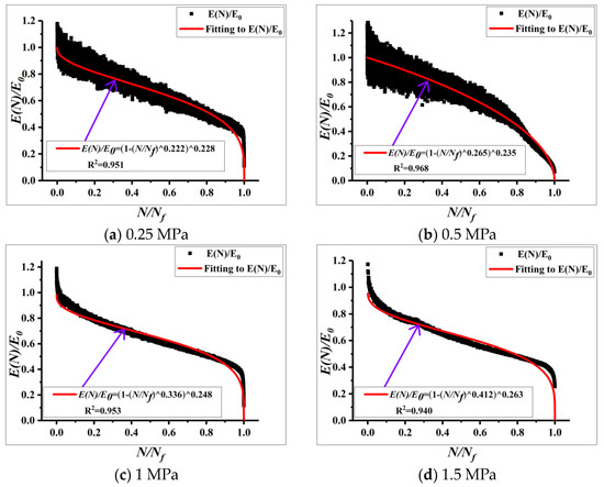
Figure 5.
Moduli decay pattern of the direct tensile fatigue tests.
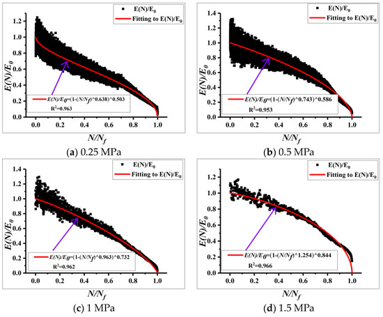
Figure 6.
Moduli decay pattern of tensile moduli measured by the indirect tensile fatigue tests.
It can be noticed from Figure 5 and Figure 6 that the decay patterns of tensile moduli that were obtained from these two test methods are similar. There are three stages: migration stage, steady stage, and destructive stage, and the whole process is nonlinear.
However, the decay rates of different stress state are different, which are caused by different fatigue resistance of asphalt. In the direct tensile test, the specimen is within a uniform tensile condition. The main factors determining its fatigue properties are the cohesion of the asphalt mortar (the adhesion of the aggregate with the asphalt and its internal friction based on the aggregate gradation). The effect of intrusion between aggregates is relatively weak [30]. During the indirect tensile tests, the transverse tensile fatigue properties mainly depend on the adhesion (between asphalt mortar and aggregates) and the internal frictional resistance.
Figure 5 and Figure 6 reflect the decay pattern of different stress levels under different stress states. In order to compare the decay pattern more obviously, this paper compared the decay pattern of tensile moduli under the same stress level. The parameters of the fitted curves for tensile stress were shown in the Table 10:

Table 10.
Fitting parameters of the tensile moduli decay curves under different test conditions.
The tensile moduli measured by indirect tensile test and direct tensile under the same stress level 1 MPa were compared. As shown in Figure 7:
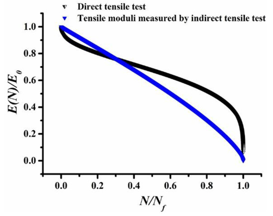
Figure 7.
The decay pattern of tensile moduli measured by the indirect tensile test and direct tensile test.
In order to compare the decay pattern more clearly, the decay Equation is simplified.
Equation (6) is simplify to , then,
where, is the ratio of the modulus of the material to the initial modulus of the undamaged state after loading the specimen to N, is the ratio of the loading cycles to the fatigue life, m and n are the material parameters related to the stress, is the first derivative of , and is the two derivative of .
While substituting parameters under the stress level of 1 MPa into Equation (8), the inflection point can be calculated, then the tangent line at the inflection point position can be adopted to compare the tangent slope. The result is as follows:
It can be noticed from Figure 7 and Table 11 that the decay patterns of tensile moduli, as measured by the indirect tensile test and the direct tensile test are nonlinear. The moduli parameters are different. The inflection point of direct tensile test is 0.381. The decay rate of direct tensile moduli decreases gradually before the inflection, while it increases after the inflection point. The inflection point of tensile moduli, as measured by the indirect tensile test is 0.114. In addition, the decay rate shows an increasing trend. There are three stages of migration stage, steady stage and destructive stage in the decay curves of the direct tensile tests and the indirect tensile tests. The decay rate of the direct tensile moduli is more quickly than that of the indirect tensile moduli during the migration state, but it is contrary during the steady stage. In addition, the decay rate of the direct tensile moduli is quicker than that of the indirect tensile moduli at the destructive stage.

Table 11.
Inflection points and slopes of decay curves of tensile moduli under different test conditions.
Similarly, the decay patterns of the compression moduli were fitted as shown in Figure 8 and Figure 9, respectively.
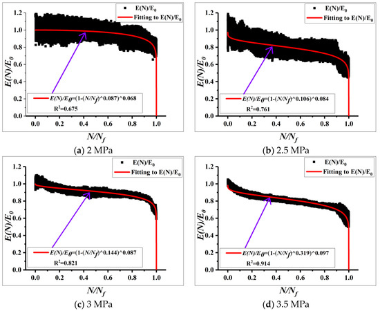
Figure 8.
Moduli decay patterns of uniaxial compression tests.
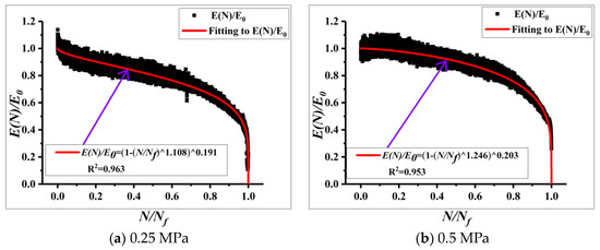
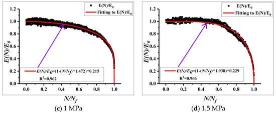
Figure 9.
Moduli decay patterns of compression moduli measured by the indirect tensile tests.
From Figure 8 and Figure 9, it can be observed that the decay patterns of compression moduli also exist three stages of migration stage, steady stage, and destructive stage, and the patterns are nonlinear. But, the decay rates are different under different stress state.
For uniaxial compression test, the specimen is in a compression stress state. The skeleton structure, composition form, and friction coefficient of aggregates determine the inter-particle frictional resistance. The main factors determining its fatigue properties are the cohesion of the aggregate particles [31]. In the indirect tensile test, fatigue properties mainly depend on the interlocking effect of aggregate when the specimens are under the compression state [32]. In summary, when the materials are in a different stress state, the factors that determine the fatigue properties are different.
In order to compare the decay pattern more obviously, this paper compared the decay pattern of compression moduli under same stress level. The parameters of the fitted curves for different stress levels are shown in Table 12:

Table 12.
Fitting parameters of fatigue moduli decay curves under different test conditions.
It is difficult to compare the moduli decay patterns. In this paper, the parameters m and n of compression moduli were fitted with stress levels. The fitting results were shown in Equations (9) and (10).
As there are four stress level (0.25, 0.5, 1, 1.5) of compression moduli, as measured by the indirect tensile test. Taking σ = 1 MPa into Equations (9) and (10), respectively, then the parameters m and n of uniaxial compression moduli under 1 MPa can be obtained, as shown in Table 13.

Table 13.
Fitting parameters of fatigue moduli decay curve in different tests method under 1 MPa stress level.
The compression moduli measured by indirect tensile test and uniaxial compression moduli under 1 MPa stress level were compared, as shown in Figure 10. The decay patterns of the two compression moduli are experienced in three stages: migration stage, steady stage, and destructive stage, and the whole process is nonlinear.
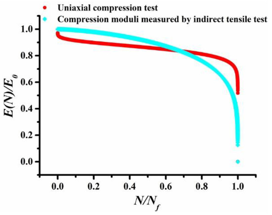
Figure 10.
Decay pattern of compression moduli.
In order to compare the decay rate, substituting the parameters in Table 13 into Equation (8), the inflection point of the decay curve can be calculated. Then, the tangent line at the inflection point position can be implemented to compare the tangent slope. The result is as follows:
From Figure 10 and Table 14, it can be notified that the compression moduli decay pattern of uniaxial compression and indirect tensile similarly exist three stages of migration stage, steady stage, and destructive stage, and the patterns are nonlinear, too. The inflection point of uniaxial compression moduli is 0.370. The decay rate decreases before the inflection point, while it increases after the inflection point. There is no inflection point of indirect tensile moduli. In order to compare the decay rate on same position, the tangency point of indirect test is also taken as 0.37. It can be observed that the tangent slope of indirect test is larger than the uniaxial compression test on tangency point position. During the migration stage, the decay rate of uniaxial compression is faster than that of the indirect tensile. During the steady stage, the decay rate of uniaxial compression is slower than that of the indirect tensile. The decay rate of uniaxial compression is also faster than that of the indirect tensile during the destructive stage.

Table 14.
Inflection points and slopes of decay curves of compression moduli under different test conditions.
As the stress level of tensile moduli and compression moduli all is 1 MPa, the decay pattern of tensile moduli and compression moduli were compared simultaneously. The values of m and n in Table 10 and Table 13 were substituted into Equation (6). Then, the fatigue moduli decay patterns were shown in Figure 11.
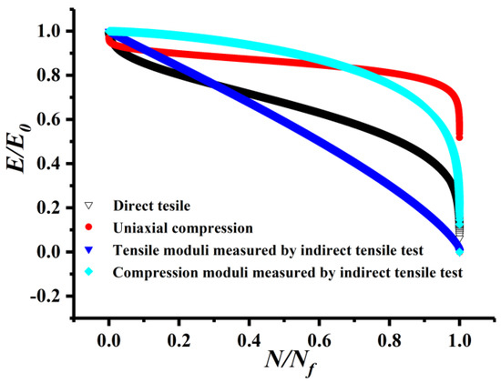
Figure 11.
Fatigue moduli decay patterns.
From Figure 11, it can be observed that the fatigue moduli decay curves exist in the three stages of migration stage, steady stage, and destructive stage. The fatigue damage characteristics of asphalt mixtures are non-linear.
However, on one hand, the decay curves of fatigue moduli under different stress levels are quite different. In one-dimensional stress states, the tensile moduli and compression moduli are also quite different. In two-dimensional stress states, the difference is obvious between the compression moduli and tensile moduli, which were both obtained from the indirect tensile test. On the other hand, the direct tensile moduli are similar to the tensile moduli obtained from the indirect tensile test. The compression moduli of uniaxial compression test are similar to the compression moduli that were obtained from the indirect tensile test.
In addition, it can be found from Table 11 and Table 14 that the inflection point of tensile moduli measured by the indirect tensile is the smallest and that of the direct tensile are the maximum. At the tangent point, the uniaxial compression has the lowest moduli decay slope and the tensile moduli, as measured by the indirect tensile test, has the largest moduli decay slope. It can be concluded that the decay rate of the tensile moduli measured by the indirect tensile test is faster than the uniaxial compression moduli at the tangent point during the course of the fatigue tests.
It also can be observed that the position of the decay curve for the compression moduli is higher than that of the tensile moduli at the same cycle ratio state. It can be concluded that the decay rate of the tensile moduli is faster than that of the compression moduli during the course of the fatigue tests, which indicates that the tensile failure is the main reason of the fatigue damage for asphalt mixture.
4. Summary and Conclusions
The fatigue tests and analysis of asphalt mixture under different loading conditions and stress levels were carried out. The following conclusions can be drawn from above:
- (1)
- Under different loading conditions, the S-N fatigue curves for the direct tensile, indirect tensile and uniaxial compression are different. Therefore, it is difficult to compare the fatigue resistance of the same asphalt mixtures in the different stress conditions, according to the traditional method.
- (2)
- There are three stages in the moduli decay curves under different stress levels and conditions, which are migration, stabilization, and destruction. The decay patterns are nonlinear.
- (3)
- The decay patterns of the direct tensile moduli and the tensile moduli, as measured by the indirect tensile test, are similar. At the same time, the decay patterns of the uniaxial compression and the compression moduli, as measured by indirect tensile test, are similar. Nevertheless, the decay patterns of the tensile and the compressive moduli are obviously different.
- (4)
- There are significant differences in the tensile and compression characteristics of asphalt mixtures. For the flexural fatigue test, the decay rate of the tensile modulus at the bottom of the specimen is greater than that of the compression modulus at the top of the specimen under the same cyclic ratio condition. So, it exhibits tensile stress failure characteristics during the flexural fatigue test of the asphalt mixture.
Author Contributions
Conceptualization, S.L. and X.F.; Methodology, S.L. and C.X.; Software, S.L.; Validation, S.L., X.F. and C.X.; Formal Analysis, X.F.; Investigation, S.L.; Resources, S.L.; Data Curation, C.X.; Writing-Original Draft Preparation, X.F. and C.X.; Writing-Review & Editing, S.L. and C.X.; Visualization, D.C.; Supervision, J.Z. and L.Y.; Project Administration, S.L.; Funding Acquisition, S.L. and J.Z.
Funding
This research was funded by National Natural Science Foundation of China (Grant number [51578081, 51608058]; The Ministry of Transport Construction Projects of Science and Technology [2015318825120]; The Guangxi Zhuang Autonomous Region Traffic and Transportation Department Transportation Projects of Science and Technology [2013-32], and The Inner Mongolia Autonomous Region Traffic and Transportation Department Transportation Projects of Science and Technology [NJ-2016-35].
Acknowledgments
This work is supported by Key Projects of Hunan Province-Technological Innovation Project in Industry [2016GK2096], National Engineering Laboratory Open Fund Project [kfh160102], Scientific and Technological Innovation Project of Hunan Province for University Graduate Students [CX2017B457]. The authors gratefully acknowledge their financial support.
Conflicts of Interest
The authors declare no conflict of interest.
References
- Ziari, H.; Babagoli, R.; Akbari, A. Investigation of fatigue and rutting performance of hot mix asphalt mixtures prepared by bentonite-modified bitumen. Road Mater. Pavement Des. 2014, 16, 101–118. [Google Scholar] [CrossRef]
- Xuedong, G.; Mingzhi, S.; Wenting, D.; Kaixuan, Z.; Jilu, L. Research on the fatigue whole life of asphalt mixture based on the nonlinear damage theory. Constr. Build. Mater. 2017, 156, 546–554. [Google Scholar] [CrossRef]
- Saboo, N.; Das, B.P.; Kumar, P. New phenomenological approach for modeling fatigue life of asphalt mixes. Constr. Build. Mater. 2016, 121, 134–142. [Google Scholar] [CrossRef]
- Liu, G.; Jia, Y.; Yang, T.; Du, H.; Zhang, J.; Zhao, Y. Fatigue performance evaluation of asphalt mixtures based on energy-controlled loading mode. Constr. Build. Mater. 2017, 157, 348–356. [Google Scholar] [CrossRef]
- Saha, G.; Biligiri, K.P. Stato-dynamic response analyses through semi-circular bending test: Fatigue life prediction of asphalt mixtures. Constr. Build. Mater. 2017, 150, 664–672. [Google Scholar] [CrossRef]
- Saha, G.; Biligiri, K.P. Modulus prediction of asphalt mixtures using dynamic semicircular bending test: Estimation algorithm and nomograph development. Int. J. Fatigue 2018, 109, 137–144. [Google Scholar] [CrossRef]
- Lv, S.; Liu, C.; Yao, H.; Zheng, J. Comparisons of synchronous measurement methods on various moduli of asphalt mixtures. Constr. Build. Mater. 2018, 158, 1035–1045. [Google Scholar] [CrossRef]
- Bańkowski, W. Evaluation of fatigue life of asphalt concrete mixtures with reclaimed asphalt pavement. Appl. Sci. 2018, 8, 469. [Google Scholar] [CrossRef]
- Lv, S.; Wang, X.; Liu, C.; Wang, S. Fatigue damage characteristics considering the difference of tensile-compression modulus for asphalt mixture. J. Test. Eval. 2018, 46. [Google Scholar] [CrossRef]
- Lv, S.; Liu, C.; Zheng, J.; You, Z.; You, L. Viscoelastic fatigue damage properties of asphalt mixture with different aging degrees. KSCE J. Civ. Eng 2018, 22, 2073–2081. [Google Scholar] [CrossRef]
- Moreno-Navarro, F.; Rubio-Gámez, M.C. A review of fatigue damage in bituminous mixtures: Understanding the phenomenon from a new perspective. Constr. Build. Mater. 2016, 113, 927–938. [Google Scholar] [CrossRef]
- You, L.; Yan, K.; Hu, Y.; Liu, J.; Ge, D. Spectral element method for dynamic response of transversely isotropic asphalt pavement under impact load. Road Mater. Pavement Des. 2018, 19, 223–238. [Google Scholar] [CrossRef]
- You, L.; Yan, K.; Hu, Y.; Zollinger, D.G. Spectral element solution for transversely isotropic elastic multi-layered structures subjected to axisymmetric loading. Comput. Geotech. 2016, 72, 67–73. [Google Scholar] [CrossRef]
- Xie, J.; Xiao, Y.; Wu, S.; Huang, J. Research on fracture characteristic of gneiss prepared asphalt mixture with direct tensile test. Constr. Build. Mater. 2012, 28, 476–481. [Google Scholar] [CrossRef]
- Lee, H.S.; Kim, J. Determination of viscoelastic poisson’s ratio and creep compliance from the indirect tension Test. J. Mater. Civ. Eng. 2009, 21, 416–425. [Google Scholar] [CrossRef]
- Zeiada, W.A.; Souliman, M.I.; Kaloush, K.E.; Mamlouk, M. Endurance limit for HMA based on healing concept using uniaxial tension-compression fatigue test. J. Mater. Civ. Eng. 2015, 26, 839–844. [Google Scholar] [CrossRef]
- Hartman, A.M.; Gilchrist, M.D.; Walsh, G. Effect of mixture compaction on indirect tensile stiffness and fatigue. J. Transp. Eng. 2001, 127, 370–378. [Google Scholar] [CrossRef]
- Darvell, B.W. Uniaxial compression tests and the validity of indirect tensile strength. J. Mater. Sci. 1990, 25, 757–780. [Google Scholar] [CrossRef]
- Lv, S.; Liu, C.; Chen, D.; Zheng, J.; You, Z.; You, L. Normalization of fatigue characteristics for asphalt mixtures under different stress states. Constr. Build. Mater. 2018, 177, 33–42. [Google Scholar] [CrossRef]
- Li, N.; Molenaar, A.A.A.; van de Ven, M.F.C.; Wu, S. Characterization of fatigue performance of asphalt mixture using a new fatigue analysis approach. Constr. Build. Mater. 2013, 45, 45–52. [Google Scholar] [CrossRef]
- (JTG F40-2004) Technical Spcifications for Construction of Highway Asphalt Pavements; Renmin Communication Press: Beijing, China, 2004.
- (JTG E42-2005) Test Methods of Aggregate for Highway Engineering; Renmin Communication Press: Beijing, China, 2005.
- (JTG E20-2011) Standard Test Methods of Asphalt and Asphalts Mixtures for Highway Engineering; Renmin Communication Press: Beijing, China, 2011.
- Wang, H.; Zhang, C.; Li, L.; You, Z.; Diab, A. Characterization of low temperature crack resistance of crumb rubber modified asphalt mixtures using semi-circular bending tests. J. Test. Eval. 2016, 44, 845–855. [Google Scholar] [CrossRef]
- Mitchell, M.R.; Link, R.E.; Huang, L.; Cao, K.; Zeng, M. Evaluation of semicircular bending test for determining tensile strength and stiffness modulus of asphalt mixtures. J. Test. Eval. 2009, 37, 122–128. [Google Scholar] [CrossRef]
- Adhikari, S.; Shen, S.; You, Z. Evaluation of fatigue models of hot-mix asphalt through laboratory testing. Transp. Res. Rec. J. Transp. Res. Board. 2009, 2127, 36–42. [Google Scholar] [CrossRef]
- Shafabakhsh, G.; Taghipoor, M.; Sadeghnejad, M.; Tahami, S.A. Evaluating the effect of additives on improving asphalt mixtures fatigue behavior. Constr. Build. Mater. 2015, 90, 59–67. [Google Scholar] [CrossRef]
- Chaboche, J.L. A review of some plasticity and viscoplasticity constitutive theories. Int. J. Plast. 2008, 24, 1642–1693. [Google Scholar] [CrossRef]
- Zheng, J.; Lv, S. Nonlinear fatigue damage model for asphalt mixtures. China J. Highw. Transpt. 2009, 22, 21–28. [Google Scholar]
- Kim, Y.K.; Woo Lee, S. Comparative study on the bond strength between direct tensile test and indirect tensile test for bonded concrete overlay. J. Korean Soc. Civ. Eng. Mag. 2013, 33, 1153–1163. [Google Scholar] [CrossRef]
- Akçaoğlu, T.; Tokyay, M.; Çelik, T. Effect of coarse aggregate size on interfacial cracking under uniaxial compression. Mater. Lett. 2002, 57, 828–833. [Google Scholar] [CrossRef]
- Carmona, S. Effect of specimen size and loading conditions on indirect tensile test results. Mater. Constr. 2009, 59, 7–18. [Google Scholar] [CrossRef]
© 2018 by the authors. Licensee MDPI, Basel, Switzerland. This article is an open access article distributed under the terms and conditions of the Creative Commons Attribution (CC BY) license (http://creativecommons.org/licenses/by/4.0/).