Featured Application
The application of a semiconductor optical amplifier (SOA) in an incoherent Optical Code Division Multiple Access (OCDMA) system based on multi-wavelength picosecond code carriers is explored for mitigation of temporal distortion of an OCDMA auto-correlation affected by the temperature induced dispersion changes in a fibre optic transmission link.
Abstract
Chromatic and temperature induced dispersion can both severely affect incoherent high data rate communications in optical fibre. This is certainly also true for incoherent optical code division multiple access (OCDMA) systems with multi-wavelength picosecond code carriers. Here, even a relatively small deviation from a fully dispersion compensated transmission link can strongly impact the overall system performance, the number of simultaneous users, and the system cardinality due to the recovered OCDMA auto-correlation being strongly distorted, time-skewed, and having its full width at half maximum (FWHM) value changed. It is therefore imperative to have a simple tunable means for controlling fibre chromatic or temperature induced dispersion with high sub-picosecond accuracy. To help address this issue, we have investigated experimentally and by simulations the use of a semiconductor optical amplifier (SOA) for its ability to control the chirp of the passing optical signal (OCDMA codes) and to exploit the SOA ability for dispersion management of a fibre link in an incoherent OCDMA system. Our investigation is done using a 19.5 km long fibre transmission link that is exposed to different temperatures (20 °C and 50 °C) using an environmental chamber. By placing the SOA on a transmission site and using it to manipulate the code carrier’s chirp via SOA bias adjustments, we have shown that this approach can successfully control the overall fibre link dispersion, and it can also mitigate the impact on the received OCDMA auto-correlation and its FWHM. The experimental data obtained are in a very good agreement with our simulation results.
Keywords:
group velocity dispersion; chirp; optical code division multiple access auto-correlation; fibre propagation; chromatic dispersion; temperature induced dispersion; super-continuum generation; optical code division multiple access transmitter; optical code division multiple access receiver/decoder; semiconductor optical amplifier 1. Introduction
Optical fibre networks are a vital means of modern communication. Today’s applications demand high data rate throughputs and this demand continues to increase. With incoherent data communication approaches, high data rates demand the use of short optical pulses as data carriers. An effective management of these short optical pulses, mainly their temporal broadening due to dispersion effects in optical fibre, is becoming increasingly challenging. It has been observed that the signals are 16 times more sensitive to chromatic dispersion at 40 Gb/s when compared to that at 10 Gb/s [1]. Therefore, to meet user demands for a much higher transmission bandwidth, the network operators face the challenge of how to adapt the existing networks to support the higher data rates that are demanded. However, without having simple ways to achieve tunable chromatic dispersion (CD) management, the current solution depends on accurate fibre length adjustments between different transmission fibre types and dispersion compensating fibre (DCF). The main disadvantage is the bulky nature of this approach. Another cost-effective and commonly used method of compensation is the use of fibre Bragg gratings (FBGs) [2]. Some other approaches include using new modulation schemes, chirp pre-compensation, electronic dispersion compensation, and the use of digital filters etc. [2,3,4].
Optical code division multiple access (OCDMA) is an advanced multiplexing scheme that is attractive for its high scalability and random access [5]. One of efficient and often used coding schemes by incoherent OCDMA systems is a two-dimensional wavelength-hopping time-spreading (2D-WH/TS) coding [6,7]. In this encoding approach, OCDMA sequences are spread simultaneously in both wavelength and time domains in order to improve the system scalability and its performance [5,6,8]. A 2D-WH/TS prime code is a class of two dimensional (2D: wavelength-time), incoherent asynchronous codes that support wavelength hopping within time-spreading over the Galois field of prime numbers with zero auto-correlation side-lobes and periodic cross-correlation functions of at most one [5]. Because 2D-WH/TS systems use multi-wavelength short picosecond code carriers, the data transmission is susceptible to the presence of chromatic dispersion in optical fibre [9]. Therefore, it is imperative to understand the influence of dispersion and to also have relatively simple means for dispersion mitigation. If untreated, the recovered OCDMA auto-correlation function (i.e., the received data pulse envelope) that is recovered by a CDMA receiver’s decoder will be distorted and broadened due to code carriers’ time-skewing [10], which is caused by chromatic dispersion in optical fibres. The multi-wavelength optical pulses that are used as OCDMA code carriers travel with different speeds since the fibre refractive index is wavelength dependent. Here also DCF modules are commonly used for CD compensation. However, the use of picosecond code carriers demands a high (sub-picosecond) dispersion compensation accuracy [11]. This is not a very practical approach if a short length of SMF-28 has to be added, requiring compensation by matching the length of the DCF fibres. There is therefore a widely recognized need for tunable dispersion compensation techniques.
Different types of tunable dispersion compensators, such as integrated tunable chirped fibre Bragg gratings (CFBG), adaptive tunable dispersion control, dispersion equalization by adjusting the equalizer to maximize the clock component, virtually imaged phase arrays (VIPA), micro electro mechanical systems (MEMS), and other methods were demonstrated [12,13,14,15,16,17]. The use of Semiconductor Optical Amplifiers (SOAs) has also been investigated for tunable dispersion control for use in incoherent OCDMA systems. In [18,19], an SOA that was located at the receiver site was investigated for its effectiveness in reshaping the OCDMA auto-correlation functions distorted by the dispersion. In [19], it was experimentally demonstrated that the influence of the fibre link temperature on the recovered OCDMA auto-correlation could be mitigated by introducing an SOA as part of the OCDMA receiver. In [20], an SOA that was located at the transmission end was used to control the chirp of OCDMA code carriers to mitigate the effect of CD on the OCDMA auto-correlation width changes at room temperature.
In this paper, to the best of our knowledge, we investigate for the first time the use of an SOA on a transmitter site to mitigate the effects of fibre temperature fluctuations that affect the received OCDMA auto-correlation that is recovered on the receiver site. We have experimentally shown, and by simulations, that a distorted OCDMA auto-correlation due to the temperature induced fibre dispersion (TD) can be corrected by manipulating the chirp of code carriers when traversing a biased SOA prior to entering the transmission link. In addition, the simultaneous effects of the varying values of group velocity dispersion (parameter β2) and fibre link temperature on the OCDMA auto-correlation width changes were also investigated. We have shown that the impact of a changing β2 (0.03–0.06) ps2/nm, when the fibre link is exposed to 50 °C, can be continuously compensated by using the SOA controlling the code carriers’ chirp. Our simulation results are in very good agreement with the experimental observations.
2. Experimental Setup
The experimental setup that we used for our investigation is shown in Figure 1. Here, the ps ML Laser produces a 1.8 ps single wavelength (1545 nm) optical clock at OC-48 rate (bit-width equal to ~400 ps), which is then passed through an optical supercontinuum generator (OSG) by PriTel, Inc. (Naperville, IL, USA). The OSG consists of a high-power erbium doped fiber amplifier and dispersion decreasing fiber (DDF). The optical clock from the ps ML Laser that was centered at 1545 nm after the amplification by an 18 dBm erbium doped fibre amplifier (EDFA) is injected into approximately a 1 km long DDF. This way, a 3.2 nm wide optical supercontinuum is generated in a spectral region of 1550–1553.2 nm. The supercontinuum is then spectrally sliced by an OCDMA encoder (OKI Industries, Saitama, Japan), which is based on four FBGs (central frequencies are: λ1 = 1551.72 nm, λ2 = 1550.92 nm, λ3 = 1552.52 nm, λ4 = 1550.12 nm) matching the 100 GHz ITU grid. The physical separation of individual FBGs is such that the encoder generates a following 2D-WH/TS OCDMA code: (1-λ2, 21-λ4, 24-λ1, 39-λ3). Here, the integer number leading λi represents the order of the time slot (called a chip) containing the carrier λi within the 400 ps long bit-width. This OCDMA code is then amplified by 15 dBm EDFA-1 and is transmitted through a 19.5 km long fibre spool that is located inside of the environmental chamber (SM-32C from Thermatron Industries, Holland, MI, USA).
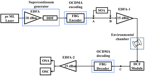
Figure 1.
Experimental setup for the chirp control investigation by SOA at a transmitter site. ps ML Laser: picosecond mode locked laser; EDFA: erbium doped fibre amplifier; DDF: dispersion decreasing fibre; FBG: fibre Bragg gratings; DCF: dispersion compensating fibre; SOA: semiconductor optical amplifier; OSA: optical spectrum analyser; OSC: oscilloscope.
At the receiving end, an OCDMA auto-correlation is recovered from the received signal by an OCDMA decoder (OKI Industries) that is matched to the OCDMA encoder. In this process, the decoder removes all delays that are imposed on individual code carriers by the encoder [21]. The result is an OCDMA auto-correlation peak, i.e., which represents the received data. This is illustrated in Figure 2. To compensate for the code carriers’ optical attenuation resulting from the fibre link attenuation, and also for the losses during the OCDMA auto-correlation recovery by the decoder, the resulted signal is amplified by a 15 dBm EDFA-2. For longer transmission distances, when the transmitted signal suffers more attenuation losses, an EDFA may be required before the OCDMA decoder. In our investigation, the decoded signal was then analysed using an optical spectrum analyser (OSA—Agilent 86146B, Agilent Technologies, Santa Clara, CA, USA) and oscilloscope, (OSC—Agilent Infiniium DCA-J 86100Cwith a 64 GHz optical sampling head, Agilent Technologies, Santa Clara, CA, USA). For future applications, to avoid the need for high bandwidth electronics, we assume using a hard-limiter in the front of the 2D-WH/TS OCDMA decoder that is similar to one demonstrated in [8]. This hard-limiter would be based on a picosecond all-optical time gating, followed by low-bandwidth electronics.
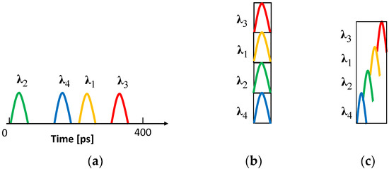
Figure 2.
Illustration of the effect of temperature induced dispersion in fibre transmission link on incoherent optical code division multiple access (OCDMA). (a) Two-dimensional wavelength-hopping time-spreading (2D-WH/TS) transmitted OCDMA code; (b) Recovered OCDMA auto-correlation—ideal case; and, (c) Recovered OCDMA auto-correlation time-skewed and compressed due to the temperature induced dispersion effects (DT < 0).
To study the effect of temperature on the transmitted OCDMA codes, the 19.5 km link was CD compensated at room temperature T = 20 °C using a commercially available dispersion compensating module DCF. In our investigations, the fibre link temperature will be varied from 20 °C to 50 °C. As a result, the code carriers will be affected by these temperature changes due to fibre refraction index temperature dependency [19]. The temperature induced dispersion coefficient DT of optical fibre is negative. Based on [22], DT = − 0.0016 ps/nm·km/°C, therefore pulses of longer wavelengths travel with higher speed ν than those of shorter wavelengths (in our case νλ4 < νλ2 < νλ1 < νλ3). This is contrary to CD where the chromatic dispersion coefficient DCD > 0. The impact of DT is twofold:
- (1)
- It causes the rise of the so-called time-skewing effect illustrated in Figure 2c. We can see that because the code carriers having a longer wavelength travel faster than those with a shorter wavelength, instead of being placed on top of each other at the fibre receiving end after the OCDMA decoder (Figure 1), as is shown in Figure 2b, the code carriers are instead time shifted (Figure 2c). The resulting OCDMA auto-correlation envelope has thus become skewed.
- (2)
- Because of finite code carriers’ linewidth and DT being negative, they will experience a temporal narrowing (squeezing) [19] (see Figure 2c). This result is opposite to the CD effect where the chromatic dispersion coefficient DCD > 0, and it would therefore cause temporal broadening of the code carriers.
Our next step is to formally describe the above.
3. Analyses of Chirp and Temperature Induced Fibre Dispersion on Optical Code Division Multiple Access Auto-Correlation
We will now develop an equation describing the OCDMA auto-correlation envelope that was recovered by the OCDMA decoder on the receiver site being affected by the initial code carriers’ chirp and fibre temperature changes.
A temporal Gaussian shape of an optical pulse affected by chirp C can be expressed as [23]:
where t is time, P0 is a peak power and the coefficient 2.77 indicates that its width τ is measured at full width at half maximum (FWHM).
In our investigation we will use a 2D-WH/TS OCDMA system based on four multi-wavelength picosecond pulses as code carriers, each pulse carrier j has a line-width of ∆λj. Carriers are spectrally separated by ∆Λj where j = 1, 2, 3, 4, respectively. Using Equation (1) and following [24] for the OCDMA auto-correlation temporal envelope that was recovered by the OCDMA receiver Rx, we can write the following expression:
In the above expression, w = 4 is the number of code carriers (wavelengths) and it is also known as the code weight. The numerator () represents time skewing among wavelength code carriers and the denominator () reflects the carrier width change due to temperature induced dispersion effects in the fibre link.
By following [20], we now develop a mathematical model for describing the effect of the code carriers’ chirp and temperature induced dispersion changes in the fibre transmission link on the OCDMA auto-correlation envelope. Because we have used the same OCDMA hardware, we used in [20], the chirp value C = 2.36 at the OCDMA encoder output (point A, Figure 1) will be considered to be the same for the purpose of this investigation.
As has already been mentioned, the 19.5 km fibre transmission link was CD compensated at a room temperature of T = 20 °C. In order to CD compensate the 19.5 km SMF-28 fibre, we applied a commercially available DCF module. Because of small dispersion mismatch between the link and DCF, this resulted in overall link overcompensation that could be represented by an average CD coefficient DCD = −0.047 ps/nm·km. We found the fibre link overall group velocity dispersion (GVD) coefficient to be β2 = +0.06 ps2/km by following the expression as [23]:
β2 = −(2πc/λ2)/DCD,
Now, by formally combining CD and TD effects, the expression for a code carrier pulse width change can be written as:
where DCD = −0.047 ps/(nm·km) represents the residual dispersion of the CD compensated fiber transmission link, L = 19.5 km is the link’s length, DT = −0.0016 ps/nm·km/°C [22], and ∆T is a fiber link temperature change. Because of using a 100 GHz FBG 2D-WH/TS OCDMA encoder for an optical supercontinuum slicing, values of ∆λj = ∆Λj = 0.8 nm.
∆τj = DCD × L × ∆λj + DT × ∆λj × L × ∆T,
At the OCDMA decoder, the frequency domain representation of the recovered OCDMA auto-correlation envelope, after L = 19.5 km of code propagation in the fibre link, can be obtained from Equation (2), by following [25] as:
again, β2 = +0.06 ps2/km is the fibre link GVD, ωj is the angular frequency of the particular code carrier j, and {exp (−i ωj2 × β2/2) × L} factors in GVD effects that are imposed by the propagation in the fibre link at a given temperature T (note, the coefficient β2 is temperature dependent).
SL(λ1−λ4) (f) = fft {SL(λ1−λ4)(t)} × {exp (−i ωj2 × β2/2) × L},
Now, in order to obtain the OCDMA auto-correlation envelope SL at the receiving end in the time domain, we need to perform an inverse Fourier transform (ifft) on Equation (5) after substituting Equations (2) and (5), we can formally write:
where for reasons indicated earlier we use C = +2.36. Based on the analyses carried out in [26], we conclude that larger C (C > 0) the code carriers have at the OCDMA transmitter output, the more broadening they will experience during fibre propagation. If the value of C can be appropriately reduced, the OCDMA auto-correlation broadening at the receiver site can be reduced or even eliminated.
SL(λ1−λ4) (t) = ifft {SL(λ1−λ4)(f)},
The possibility of using the SOA for the code carriers chirp control to eliminate fibre temperature induced dispersion DT < 0 will be investigated next, first theoretically using the developed Equation (6), and then experimentally by inserting an SOA between points A and B (see Figure 1). The temperature range in our investigation will be from 20 °C to 50 °C.
4. Comparison of Simulation with Experimental Results
The time-domain representation of the OCDMA USER-1 code is shown in Figure 3a. The experimentally obtained OCDMA auto-correlation that was recovered by the OCDMA decoder after OCDMA code travelled L = 19.5 km at room temperature T = 20 °C is shown in Figure 3b. The measured FWHM width was found to be 12 ps. This experiment was then repeated for T = 50 °C and the recovered OCDMA auto-correlation is shown in Figure 3c. We can see that the FWHM width has been broadened to 13 ps by this 30 °C increase in temperature. The corresponding results that are based on our simulations are shown in Figure 4. Figure 4a shows the simulated OCDMA auto-correlation envelope SL=19.5;T=20 that was obtained when the fibre temperature was T = 20 °C and the code propagation distance L = 19.5 km. The calculated FWHM value is 12 ps, which is identical to the value that was obtained in our experiment (see Figure 3b). Similarly, simulations of the recovered OCDMA auto-correlation envelope SL=19.5;T=50 for the temperature T = 50 °C is shown in Figure 4b. Here, the calculated FWHM value is 12.8 ps and it is in very good agreement with the experimentally observed 13 ps seen in Figure 3c.
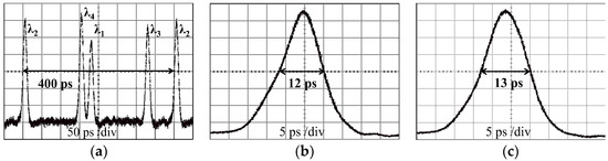
Figure 3.
(a) OCDMA encoder output showing a user-1 (1-λ2, 21-λ4, 24-λ1, 39-λ3) 2D-WH/TS OCDMA code 400 ps long as seen by a bandwidth limited oscilloscope with 64 GHz optical sampling head; (b) Recovered OCDMA autocorrelation by the OCDMA decoder at the room temperature T = 20 °C (FWHM width = 12 ps); and, (c) at T = 50 °C (FWHM width = 13 ps), respectively.
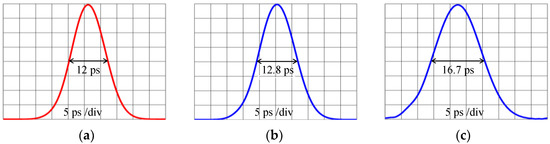
Figure 4.
Simulations of the recovered OCDMA auto-correlation SL;T envelope by the OCDMA decoder: (a) for L = 19.5 km and T = 20 °C the FWHM width = 12 ps; (b) for L = 19.5 km and T = 50 °C the FWHM width = 12.8 ps; and, (c) for L = 40 km and T = 80 °C the FWHM width = 16.7 ps.
To further emphasise the severity of detrimental effects of temperature induced fiber dispersion, Figure 4c shows the recovered OCDMA auto-correlation envelope S L=40;T=80 simulated for a fiber length L = 40 km when exposed to the temperature T = 80 °C. The corresponding FWHM value is 16.7 ps.
Our next step was to experimentally investigate a possibility of using the SOA to restore the OCDMA auto-correlation width that is affected by fibre temperature increases to its original value that was observed at room temperature, T = 20 °C. To conduct this investigation, we inserted an SOA (OPA-20-N-C, Kamelian, Glasgow, UK) at the transmission site between point A and B (see Figure 1). The role of the SOA will be to control the incoming chirp of the code carriers passing through the SOA by changing the bias current, I. This technique is known as a pre-chirping.
Figure 5 shows the experimentally obtained OCDMA auto-correlations that were recovered by the OCDMA decoder when the OCDMA code first passed the biased SOA and then travelled L = 19.5 km in the transmission link that was exposed at temperature T = 50 °C. The OCDMA auto-correlations that are shown in Figure 5a–c were obtained for SOA bias currents I = 42 mA, 14 mA, and 8 mA, respectively, and resulted in respective FWHM values of 14 ps, 13 ps, and 12 ps. The loss/gain of SOA w.r.t. the various bias currents have been shown in Figure 6.
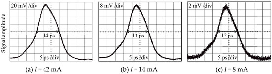
Figure 5.
Experimentally recovered OCDMA auto-correlation by the OCDMA decoder for the fibre link temperature T = 50 °C and SOA bias current set to: (a) I = 42 mA (FWHM width = 14 ps); (b) I = 14 mA (FWHM width = 13 ps); and, (c) I = 8 mA (FWHM width = 12 ps), respectively.
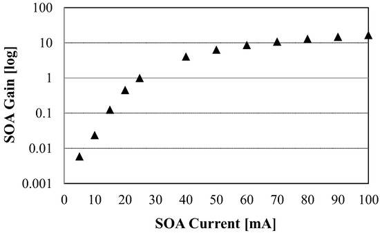
Figure 6.
SOA Gain vs. Drive Current.
Because transmitting low signal levels can affect the system’s performance and bit error rate (BER), an EDFA-1 on the transmitter site (see Figure 1) was used to amplify the signal.
Figure 7 shows the corresponding simulations of the experimental results that were shown before in Figure 5 i.e., the recovered OCDMA auto-correlation envelope SL=19.5;T=50 for the OCDMA code propagation distance L = 19.5 km, fibre link temperature T = 50 °C, and chirp value: (a) C = 5 resulting in the FWHM width = 14.2 ps; (b) C = 3 resulting in the FWHM width = 13 ps; and, (c) C = 1 resulting in the FWHM width = 12 ps, respectively.
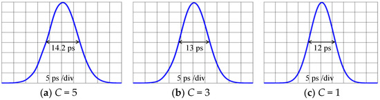
Figure 7.
Simulations of the recovered OCDMA auto-correlation envelope SL=19.5;T=50 for OCDMA code propagation distance L = 19.5 km, T = 50 °C, and C equals to (a) 5 resulting FWHM width = 14.2 ps; (b) 3 resulting FWHM width = 13 ps; and, (c) 1 resulting FWHM width = 12 ps, respectively.
Next, we have investigated the cumulative effect of the varying value of the transmission link GVD (parameter β2) on OCDMA auto-correlation FWHM’s relative changes for the code transmission in an L = 19.5 km fibre link that was exposed to a temperature of T = 50 °C. We have shown (see Figure 8) that the impact of changing β2 (0.03–0.06) ps2/nm (affected by T = 50 °C) can also be compensated using the SOA by controlling the chirp of OCDMA code carriers.
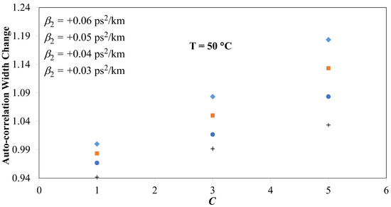
Figure 8.
Compensation of the impact of β2 on OCDMA auto-correlation width changes by using an SOA to control code carriers’ chirp at T = 50 °C.
One of the key performance indicators for incoherent OCDMA systems is a power ratio between the recovered auto-correlation peak and cross-correlation noise. In [27], it was shown that this ratio 5:1 would worsen to 2.6:1 due to 20 °C temperature fluctuations in fibre, thus strongly affecting the system BER [28]. As shown in [29], the OCDMA system transmission quality and the BER are affected by the pulse shape. As such, a skewed pulse profile of the recovered OCDMA auto-correlation will also impact the system BER and the overall system performance.
5. Discussion
Our recent work has been focused on the application of SOAs for improving the performance of incoherent OCDMA systems that are based on a 2D-WH/TS coding scheme using multi-wavelength picosecond code carriers. In [19], we reported for the first time the use of an SOA on the receiver site to continuously compensate for the broadening of the OCDMA auto-correlation due to the temperature induced dispersion in the optical fibre (the temperature induced dispersion coefficient DT < 0 in SMF-28). The SOA compensation was applied directly on the distorted OCDMA auto-correlation composed of multi-wavelength code carriers sitting on top of each other. We have shown that the broadening of the OCDMA auto-correlation width due to the fibre temperature induced dispersion can be mitigated using the twin SOA by controlling its chirp through bias current adjustments once the OCDMA auto-correlation is recovered by the OCDMA decoder. In [18], we investigated the use of an SOA that was also placed on the receiver site for a continuous manipulation of the broadened OCDMA auto-correlation due to fibre link CD (chromatic dispersion coefficient DCD > 0 in SMF-28). The SOA compensation was applied directly on the distorted OCDMA auto-correlation composed of four multi-wavelength code carriers sitting on top of each other. In this configuration, we had to use a picosecond optical pulse called a holding beam (OP/HB) synchronized with the OCDMA auto-correlation at the SOA input to be able to demonstrate that the OCDMA auto-correlation that was broadened by the fibre chromatic dispersion can be continuously ‘compressed’. In [20], we reported the use of an SOA on the transmitter site (right after the OCDMA encoder) to compensate the OCDMA auto-correlation broadening due to the fibre chromatic dispersion (DCD > 0), we observed on the OCDMA receiver site by controlling the chirp of the individual multi-wavelength OCDMA code carriers spread over a bit period before the code is launched into a fibre link.
In this paper, we have investigated for the first time how controlling the chirp of the OCDMA code carriers by the SOA prior to entering the fibre transmission link that was exposed to varying temperature (20 °C to 50 °C) will influence the recovered OCDMA auto-correlation and its width at the receiver site. We have shown both experimentally and by using simulations that the distorted OCDMA auto-correlation due to temperature induced fibre dispersion (DT < 0) can be corrected by manipulating the chirp of OCDMA code carriers when traversing the biased SOA before entering the transmission link. In addition, the effects of varying values of GVD (parameter β2) on the OCDMA auto-correlation width were also investigated. We have shown that the impact of a changing β2 (0.03–0.06) ps2/nm when the fibre link was exposed to 50 °C could be compensated by controlling the code carriers’ chirp by placing an SOA on the transmitting site. Our simulation results are in very good agreement with experimental observations.
6. Conclusions
The real communication systems that were operating under changing environmental conditions may experience temperature variations along the transmission link. These variations may not be uniform and would locally change the transmission link properties. The local temperature changes will inflict local GVD changes, which in turn will cause deviations from the ‘originally designed steady state’ fibre dispersion compensation. Since the dispersion is a cumulative effect, it will manifest itself at the receiving end as a time and temperature varying disturbance. To mitigate it would require to dynamically control the SOA.
Author Contributions
I.G. conceived and designed the experiments; contributed to data analyses and writing the paper; supervised the research work; Md.S.A. performed the experiments; contributed to data analyses; designed the analysing tools; contributed to writing the paper.
Acknowledgments
This work was supported by the European Union’s Horizon 2020 Research and Innovation Program through the Marie Sklodowska-Curie under Grant 734331.
Conflicts of Interest
The authors declare no conflict of interest. The funding sponsors had no role in the design of the study; in the collection, analyses, or interpretation of data; in the writing of the manuscript, and in the decision to publish the results.
References
- Willner, A.E.; Hoanca, B. Fixed and tunable management of fiber chromatic dispersion. In Optical Fiber Telecommunications IV-B, 4th ed.; Elsevier: New York, NY, USA, 2002; pp. 642–724. [Google Scholar]
- Norgard, G. Chromatic Dispersion Compensation: Extending Your Reach. Available online: http://www.datacenterjournal.com/chromatic-dispersion-compensation-extending-reach/ (accessed on 25 March 2018).
- Singh, M. Different dispersion compensation techniques in fiber optic communication system: A survey. Int. J. Adv. Res. Electron. Commun. Eng. 2015, 4, 2236–2240. [Google Scholar]
- Karar, A.S.; Cartledge, J.C.; Harley, J.; Roberts, K. Electronic pre-compensation for a 10.7-Gb/s system employing a directly modulated laser. J. Lightwave Technol. 2011, 29, 2069–2076. [Google Scholar] [CrossRef]
- Yang, G.C.; Kwong, W.C. Prime Codes with Applications to CDMA Optical and Wireless Networks; Artech House: Boston, MA, USA, 2002. [Google Scholar]
- Tanceski, L.; Andonovic, I. Wavelength hopping/time spreading code division multiple access systems. Electron. Lett. 1994, 30, 1388–1390. [Google Scholar] [CrossRef]
- Yegnanarayanan, S.; Bhushan, A.S.; Jalali, B. Fast wavelength-hopping time-spreading encoding/decoding for optical CDMA. IEEE Photon. Technol. Lett. 2000, 12, 573–575. [Google Scholar] [CrossRef]
- Glesk, I.; Prucnal, P.R.; Andonovic, I. Incoherent ultrafast OCDMA receiver design with 2 ps all-optical time gate to suppress multiple-access interference. IEEE J. Sel. Top. Quantum Electron. 2008, 14, 861–867. [Google Scholar] [CrossRef]
- Dang, N.T.; Pham, A.T.; Cheng, Z. Impact of GVD on the performance of 2-D WH/TS OCDMA systems using heterodyne detection receiver. IEICE Trans. Fundam. Electron. Commun. Comput. Sci. 2009, 94, 1182–1191. [Google Scholar] [CrossRef]
- Ng, E.K.; Weichenberg, G.E.; Sargent, E.H. Dispersion in multiwavelength optical code-division multiple-access systems: Impact and remedies. IEEE Trans. Commun. 2002, 50, 1811–1816. [Google Scholar] [CrossRef]
- Idris, S.K.; Osadola, T.B.; Glesk, I. Investigation of all-optical switching OCDMA testbed under the influence of chromatic dispersion and timing jitter. J. Eng. Technol. 2013, 4, 51–65. [Google Scholar]
- Eggleton, B.J.; Ahuja, A.; Westbrook, P.S.; Rogers, J.A.; Kuo, P.T.; Nielsen, N.; Mikkelsen, B. Integrated tunable fiber gratings for dispersion management in high-bit rate systems. J. Lightwave Technol. 2000, 18, 1418–1432. [Google Scholar] [CrossRef]
- Tanizawa, K.; Hirose, A. Adaptive control of tunable dispersion compensator that minimizes time-domain waveform error by steepest descent method. IEEE Photon. Technol. Lett. 2006, 18, 1466–1468. [Google Scholar] [CrossRef]
- Sano, A.; Kataoka, T.; Tomizawa, M.; Hagimoto, K.; Sato, K.; Wakita, K.; Kato, K. Automatic dispersion equalization by monitoring extracted-clock power level in a 40-Gbit/s, 200-km transmission line. In Proceedings of the 22nd European Conference on Optical Communication, Oslo, Norway, 19 September 1996; Volume 2, pp. 207–210. [Google Scholar]
- Ooi, H.; Nakamura, K.; Akiyama, Y.; Takahara, T.; Terahara, T.; Kawahata, Y.; Isono, H.; Ishikawa, G. 40-Gb/s WDM transmission with virtually imaged phased array (VIPA) variable dispersion compensators. J. Lightwave Technol. 2002, 20, 2196–2203. [Google Scholar]
- Neilson, D.T. Advanced MEMS devices for channelized dispersion compensation. In Proceedings of the Optical Fiber Communications Conference (OFC2004), Los Angeles, CA, USA, 22 February 2004; Volume 1. [Google Scholar]
- Wielandy, S.; Westbrook, P.S.; Fishteyn, M.; Reyes, P.; Schairer, W.; Rohde, H.; Lehmann, G. Demonstration of automatic dispersion control for 160 Gbit/s transmission over 275 km of deployed fibre. Electron. Lett. 2004, 40, 690–691. [Google Scholar] [CrossRef]
- Ahmed, M.S.; Abuhelala, M.S.K.; Glesk, I. Managing dispersion-affected OCDMA auto-correlation based on PS multiwavelength code carriers using SOA. IEEE/OSA J. Opt. Commun. Netw. 2017, 9, 693–698. [Google Scholar] [CrossRef]
- Ahmed, M.S.; Glesk, I. Mitigation of temperature induced dispersion in optical fiber on OCDMA auto-correlation. IEEE Photon. Technol. Lett. 2017, 29, 1979–1982. [Google Scholar] [CrossRef]
- Ahmed, M.S.; Glesk, I. Management of OCDMA auto-correlation width by chirp manipulation using SOA. IEEE Photon. Technol. Lett. 2018, 30, 785–788. [Google Scholar] [CrossRef]
- Huang, J.F.; Yang, C.C. Reductions of multiple-access interference in fiber-grating-based optical CDMA network. IEEE Trans. Commun. 2002, 50, 1680–1687. [Google Scholar] [CrossRef]
- Kato, T.; Koyano, Y.; Nishimura, M. Temperature dependence of chromatic dispersion in various types of optical fiber. Opt. Lett. 2000, 25, 1156–1158. [Google Scholar] [CrossRef] [PubMed]
- Agrawal, G.P. Nonlinear Fiber Optics; Academic Press: Cambridge, MA, USA, 2007. [Google Scholar]
- Osadola, T.B.; Idris, S.K.; Glesk, I.; Kwong, W.C. Effect of variations in environmental temperature on 2D-WH/TS OCDMA code performance. J. Opt. Commun. Netw. 2013, 5, 68–73. [Google Scholar] [CrossRef]
- Wright, E.M. Module 3–Numerical Pulse Propagation in Fibers. Available online: http://data.cian-erc.org/supercourse/Graduatelevel/module_3/3_SC_GRAD_LEVEL_Module3_wright.pdf (accessed on 25 March 2018).
- Abramczyk, H. Dispersion Phenomena in Optical Fibers. Virtual European University on Lasers. Available online: http://www.mitr.p.lodz.pl/evu/wyklady/ (accessed on 25 March 2018).
- Tsai, C.Y.; Yang, G.C.; Lin, J.S.; Chang, C.Y.; Glesk, I.; Kwong, W.C. Pulse-power-detection analysis of incoherent O-CDMA systems under the influence of fiber temperature fluctuations. J. Lightwave Technol. 2017, 35, 2366–2379. [Google Scholar] [CrossRef]
- Majumder, S.P.; Azhari, A.; Abbou, F.M. Impact of fiber chromatic dispersion on the BER performance of an optical CDMA IM/DD transmission system. IEEE Photon. Technol. Lett. 2005, 17, 1340–1342. [Google Scholar] [CrossRef]
- Islam, M.J.; Halder, K.K.; Islam, M.R. Effect of optical pulse shape on the performance of OCDMA in presence of GVD and pulse linear chirp. Int. J. Comput. Sci. Eng. 2010, 2, 1041–1046. [Google Scholar]
© 2018 by the authors. Licensee MDPI, Basel, Switzerland. This article is an open access article distributed under the terms and conditions of the Creative Commons Attribution (CC BY) license (http://creativecommons.org/licenses/by/4.0/).