Review

A Review of MEMS Scale Piezoelectric Energy Harvester

School of Electro-Mechanical Engineering, Xidian University, Number 2 Taibai South Road, Xi’an 710071, China
*
Author to whom correspondence should be addressed.
Appl. Sci. 2018, 8(4), 645; https://doi.org/10.3390/app8040645
Submission received: 8 March 2018 / Revised: 13 April 2018 / Accepted: 17 April 2018 / Published: 20 April 2018
(This article belongs to the Section Energy Science and Technology)

Abstract

:
Piezoelectric energy harvester (PEH) is emerging as a novel device which can convert mechanical energy into electrical energy. It is mainly used to collect ambient vibration energy to power sensors, chips and some other small applications. This paper first introduces the working principle of PEH. Then, the paper elaborates the research progress of PEH from three aspects: piezoelectric materials, piezoelectric modes and energy harvester structures. Piezoelectric material is the core of the PEH. The piezoelectric and mechanical properties of piezoelectric material determine its application in energy harvesting. There are three piezoelectric modes, d31, d33 and d15, the choice of which influences the maximum output voltage and power. Matching the external excitation frequency maximizes the conversion efficiency of the energy harvester. There are three approaches proposed in this paper to optimize the PEH’s structure and match the external excitation frequency, i.e., adjusting the resonant frequency, frequency up-converting and broadening the frequency bandwidth. In addition, harvesting maximum output power from the PEH requires impedance matching. Finally, this paper analyzes the above content and predicts PEH’s future development direction.

Graphical Abstract

1. Introduction

In recent years, wireless sensor network technology has been widely used in environmental monitoring, health care, urban temperature detection, agricultural production and other fields [1,2,3,4,5,6]. The main power supply for sensor nodes still relies on chemical battery, which offers limited energy storage. Further, as the sensor nodes are widely distributed, it would be difficult to replace and maintain the battery.
Specifically, energy harvesting technology converts other forms of energy into electrical energy, which is then collected to power the circuit or device [7]. Several forms of energy exist in the environment, such as mechanical energy, thermal energy, nuclear energy, solar energy, chemical energy, etc. [8]. Among them, mechanical energy is the most widely distributed.
According to the different principles, mechanical energy harvester can be divided into three categories, i.e., electromagnetic energy harvester, electrostatic energy harvester and piezoelectric energy harvester (PEH) [9,10,11,12,13]. Comparing electromagnetic and electrostatic ones, PEH has a higher energy density and is suitable to harvest vibration energy [14].
Generally, PEH can be classified into three groups: (1) macroscale; (2) MEMS scale; and (3) nanoscale. The size of a PEH affects a variety of parameters such as its weight, fabrication method, achievable power output level, and potential application areas. For example, nanoscale PEH can be motivated by rubbing, pressing or pulling [15,16,17]. It is suitable to harvest energy from human motion. As to larger scale PEHs, they are mainly motivated by ambient vibration, especially vibration with fixed frequency.
At present, there are still problems that limit the application of PEH: (1) the power loss in rectification circuit caused by the low output voltage [18]; (2) the narrow working frequency bandwidth of the energy harvester [9,19,20]; and (3) the mismatch of the frequency between the PEH and the environment [21,22].
This article mainly discusses the MEMS scale PEH. The following section introduces a general model of energy harvester and describes the research progress of PEHs from three aspects: piezoelectric materials, piezoelectric modes and energy harvesters’ structure. These contents are analyzed in Section 3. Section 4 predicts the future development of PEHs.

2. Research Progress of PEH

In 2004, Sodano et al. [23] first developed the model of the PEH, which consists of cantilever beam, piezoelectric material and electrodes. The piezoelectric material is interfaced to the cantilever beam near the fixed end, and the electrode is connected to the piezoelectric material to derive the current. When the external excitation load is applied to the base of the energy harvester, the cantilever beam moves with it. Thus, the piezoelectric material is subjected to compression deformation and a voltage difference occurs on the surface of the piezoelectric material. By designing appropriate rectifier circuit to be connected to the electrodes, the current generated from the PEH is finally exported and stored.

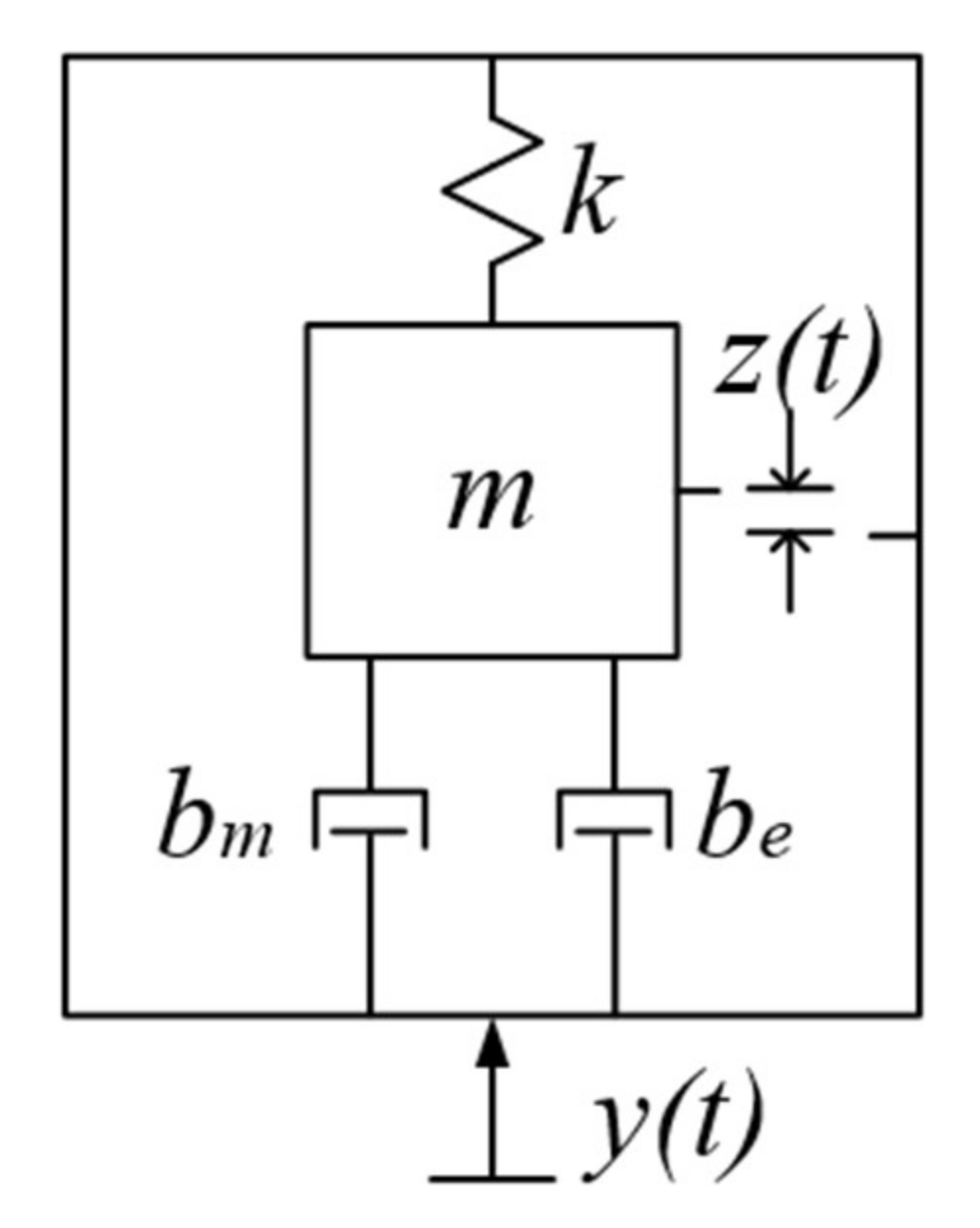
2.1. General Model of Energy Harvester

In 1995, Williams and Yates [24] proposed a model which was based on linear system theory to simulate the energy harvester. The model consists of a seismic mass, m, a spring, k, and damping, d. The model can accurately simulate the electromagnetic energy harvester mentioned in their article, but it is only feasible when the damping and stiffness are linear. For PEHs, the model needs to be changed because the impact of the electrical system on the mechanical system is not linear. Even so, important conclusions of the model can be promoted on PEHs. Based on this, Roundy [25] further decomposed the damping into electrically induced damping and mechanical damping in 2002. The improved mass–spring–damping system is shown in Figure 1. The system consists of a mass m, a spring with a stiffness k as well as the electrically induced damping be and the mechanical damping bm. While applying an external sinusoidal displacement load y ( t ) = Y 0 cos ( ω t ) with the amplitude Y0 on the model, the relative motion of the mass with respect to the housing would be z(t).
The differential equation of the model can be expressed by Equation (1):
m z ¨ + ( b e + b m ) z ˙ + k z = m y ¨
The power converted is the product of the force on the mass and its velocity. Thus, it can be shown as Equation (2):
P = k z ( y ˙ + z ˙ )
Combining Equations (1) and (2), the power converted can be expressed as:
P c = m ζ e ω n ω 2 ( ω ω n ) 3 Y 0 2 ( 2 ζ T ω ω n ) 2 + ( 1 ( ω ω n ) 2 ) 2
where ζe represents electrical damping ratio; ζT indicates the combined damping ratio (ζT = ζe + ζm); ω is the input frequency; and ωn suggests the natural frequency (or resonant frequency) of the model.
When the model’s resonant frequency matches the input frequency, the energy harvester can obtain the maximum conversion energy, as shown in Equation (4). Furthermore, the equation also shows that as the input frequency increases, the power converted Pc rises.
P c = m ζ e ω 3 Y 2 4 ζ T 2

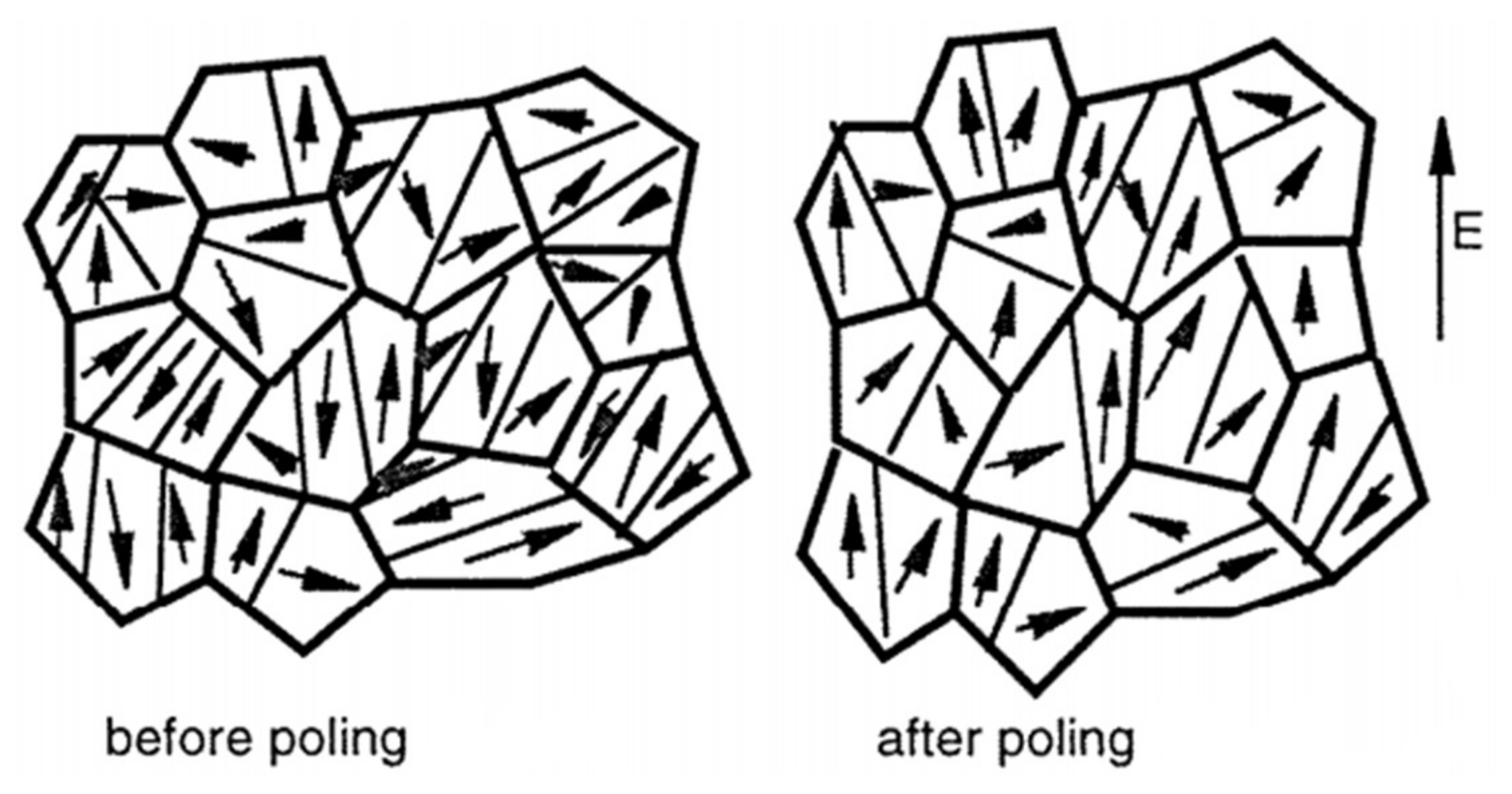
2.2. Research Progress of Piezoelectric Materials

Piezoelectric material is a class of solid materials that can accumulate electric charge in response to applied mechanical stress. In 1880, Pierre and Jacques Curie [26] discovered the piezoelectric effect of quartz crystals. Since then, more piezoelectric materials have been found. These crystals have the characteristic of low crystal symmetry. The crystal is also prone to polarization.
Usually at elevated temperatures, polycrystalline ferroelectric materials may be brought into a polar state by applying a strong electric field [27], as shown in Figure 2. For a single crystal, it does not contain domains and is said to be in a single-domain or monodomain state.
The constitutive equations for piezoelectric material, which describe the direct piezoelectric effect, are shown in Equations (5) and (6):
δ = σ / Y + d E
D = ε E + d σ
where δ represents the mechanical strain, σ the mechanical stress, Y the Young’s modulus, D the charge density, E the electric field, ε the dielectric constant, and d the piezoelectric constant.
Equations (5) and (6) are coupled together via the piezoelectric coupling term d. They provide the mechanism for power generation from vibrations. The voltage generated by the piezoelectric material is proportional to the distance between electrodes L, voltage constant gij and stress σxx as shown in Equation (7) [28]. The voltage constant gij can be derived from Equation (8), where dij is the piezoelectric constant, εr is the relative dielectric constant and ε0 is the permittivity of vacuum [29].
V o c = σ x x g i j L
g i j = d i j ε r ε 0
From Equations (7) and (8), output power is affected by piezoelectric material parameters, the voltage constant gij and the piezoelectric constant dij. Therefore, the d-g product is an important characteristic of piezoelectric materials.
Piezoelectric materials are roughly divided into inorganic and organic matters. At present, the common inorganic piezoelectric materials are piezoelectric single crystals and piezoelectric ceramics (polycrystalline). Organic piezoelectric materials generally refer to piezoelectric polymers such as polyvinylidene fluoride (PVDF) [30]. In recent years, some organic nanostructures through special processing, such as nanotubes [15], nanowires [16], and nanoparticles [17], are also found to have piezoelectric activity.
Among these materials, nanostructures with high effective piezoelectric constant are used for energy harvesting in nanoscale PEHs. Recent reports have shown high conversion efficiency in nanoscale PEHs. Besides, nanostructures are lead-free and environment friendly. For larger scale PEHs, piezoelectric ceramics is the largest material group for piezoelectric devices, while piezoelectric polymer demonstrates fastest growth due to its light weight and small size. In addition, the piezoelectricity and dielectric constant of the piezoelectric single crystal are lower than that of piezoelectric ceramics. By contrast, although the piezoelectric polymer has low density, low impedance, the strain constant and the piezoelectric constant is relatively low. At present, some people are trying to apply piezoelectric polymer to nanoscale PEHs [31,32]. Comparing the above two materials, piezoelectric ceramics have some advantages: (1) the piezoelectric constant and dielectric constant are higher; (2) higher plasticity of the shape; and (3) material composition is easy to be controlled, thereby improving its prospects. However, it should be noted that the stability and energy consumption of the piezoelectric materials still need to be further studied. Overall, the piezoelectric material has great potential for development and application.
To protect the environment, piezoelectric ceramics are now developing towards lead-free direction such as NaNbO3 and K0.5Na0.5TiO3 [33]. The sintering of these kinds of material is a challenge. In 2005, Guo et al. [34] prepared (Na0.5K0.5)NbO3-LiTaO3 using conventional mixed oxide route and found it was a good lead-free piezoelectric ceramic. Its piezoelectric constant d33 was up to 200 pC/N, and the plane electromechanical coefficient Kp reached 36%. The doping amount of LiTaO3 affected the phase of the material. In 2006, Li et al. [35] studied (Na0.5K0.5)NbO3 by using the spark plasma sintering (SPS) method with advantage of low-temperature sintering. The Curie temperature was 395 °C and the highest dielectric constant εr was 606, but the piezoelectric constant (148 pC/N) was lower than that in the report of Guo et al. In the same year, Lin et al. [36] studied the [Bi0.5(Na1−x−yKxLiy)0.5]TiO3. They found that the piezoelectric constant (231 pC/N) and the maximum dielectric constant (1190) reached the peak when x/y = 0.2/0.1. It should be noted that doping could increase the Curie temperature or the quality of grain growth, but d33 and Kp would decrease slightly [37,38]. In 2016, Shi et al. [39] studied the effect of Fe on the piezoelectric properties and fatigue behavior of (Bi0.5+x/2Na0.5−x/2)0.94-Ba0.06Ti1−xFexO3 (BNBT-xFe). They found that the induction of Fe in the electric field resulted in the decrease in the ferroelectric-relaxor transition temperature, but the strain would increase. In addition to doping, optimizing the preparation of materials could also improve the performance of piezoelectric materials [40].
Table 1 lists some parameters of the piezoelectric materials. From the table, traditional piezoelectric ceramics, lead zirconate titanate (PZT), mostly have high piezoelectric constants. The piezoelectric properties of lead-free piezoelectric materials can be enhanced by doping. There are many reports on doping showing the importance of doping for piezoelectric materials. The max piezoelectric constant d33 stood at 295 pC/N. The commonly used preparation method is the solid-state liquid-phase sintering technique. In addition, the planar Kp and thickness Kt electromechanical coupling coefficients were between 30% and 50%. However, the maximum dielectric permittivity differed significantly. The reason for this might because of the difference properties of the piezoelectric ceramic or ratio.

2.3. Research and Improvement of Piezoelectric Modes

The PEHs depend on the direct piezoelectric effect to convert vibration energy to electrical energy. According to the relationship between the stress and polarization direction of the piezoelectric material, the piezoelectric modes of the PEHs can be divided into d31, d33 and d15 [46,47,48]. The piezoelectric material is exposed to bending stress when the PEH is operated in d31 and d33 mode. By contrast, the piezoelectric material is exposed to torsion stress when the PEH is operated in d15 mode.

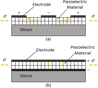
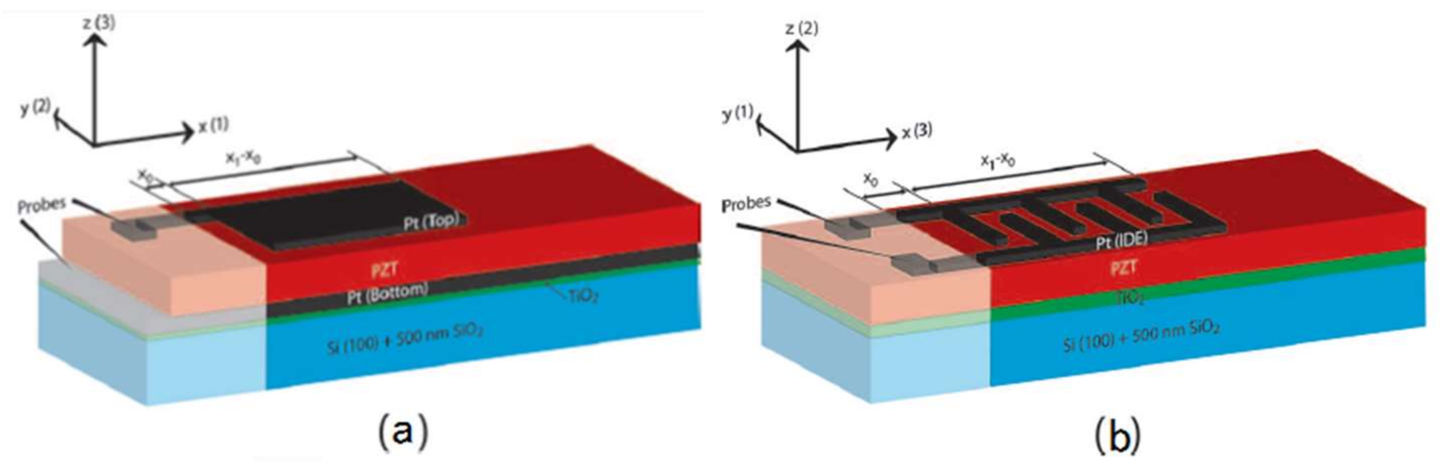
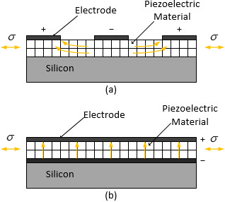
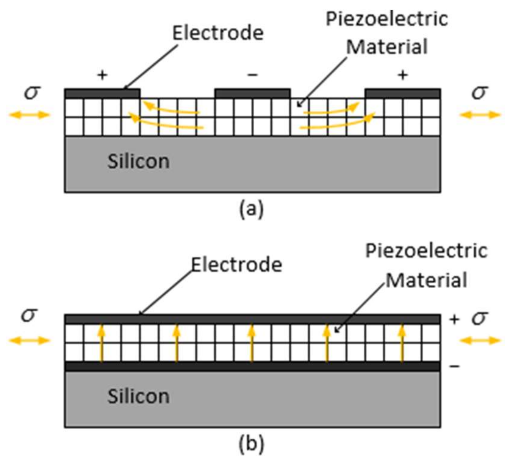
2.3.1. Piezoelectric Energy Harvesters in d31 and d33 Mode

The PEHs possess parallel plate electrodes in d31 mode with the direction of polarization perpendicular to the direction of applied stress. By contrast, a d33 mode PEH is covered with the interdigital electrodes. In addition, the polarization direction is parallel to the direction of applied stress. Furthermore, the device in d33 mode has relatively complex structure compared with d31. The electrode configurations and poling direction of the d31 devices and the d33 devices are, respectively, shown in Figure 3 and Figure 4.
Reports on d31 mode PEHs are relatively more compared to the other two modes PEHs owing to its simplicity of fabrication. By contrast, d33 is normally twice d31 according to the study of piezoelectric material listed in Sherman and Butler’s research [49]. Typically, the piezoelectric material in the PEH is thin, which leads to smaller distance between electrodes of the d31 mode device than that of the d33 mode device. Therefore, the d33 mode PEHs have advantage in generating higher output voltage while the d31 mode PEHs have potential in generating larger electric current. Since most of the rectifier circuit designs contain diodes, the generated voltage after flowing through the rectifier circuit will be reduced. This is also the reason the high output voltage can reduce the power loss in the rectifier circuit.
In 2013, Kim and others [50] studied the performance difference between the d31 mode and the d33 mode of PEHs. The experiments showed that the maximum output power was 2.15 μW for the PEH in d31 mode, while it reached 1.71 μW in d33 mode. The reason the d31 mode device has higher output power than the d33 mode device is that the matching impedance in the d31 mode device is lower relatively. Besides, there exists a “dead area” under the electrode in the d33 device, which causes it a lower efficiency [51]. However, the proportion of “dead area” under the electrode can be reduced by altering the electrode width and spacing. The simulation result showed that, when the interdigital electrode width of the d33 mode PEH was lower than 2 μm and the interdigital electrode spacing was 8–20 μm, its output power was higher than that of d31 mode. Considering that the output voltage of the d33 mode device was higher, the generated electricity through the rectifier circuit had less loss.
In 2013, Chidambaram [52] mentioned two models to calculate the relative permittivity (εr) of the PEH film in d33 mode in his research. One calculated an approximation of the permittivity (εr,IDE(approx.)) without considering the “dead area” effect. The other calculated a more accurate solution (εr,IDE(Gevorgian)) by using conformal mapping method with Schwarz–Christoffel transformation [53]. εr,IDE(Gevorgian) could be derived by multiplying εr,IDE(approx.) and the factor α, which was decided by the thickness of the piezoelectric material, the finger width and gap of the interdigital electrodes. As the thickness of the piezoelectric material decreased and the finger gap of the interdigital electrodes increased, α was close to 1, which indicated that the proportion of the “dead area” in piezoelectric material reduced. In addition, the finger width had little impact on α. If taking no account of “dead area” effect, the PEHs in d33 mode could generate 23% more electrical energy, with an order of magnitude higher voltage. Besides, the d33 mode device had about four orders of magnitude lower leakage currents compared with the d31 mode device, indicating lower power loss inside the piezoelectric material for this kind of electrodes.
Aiming at solving the problem that the piezoelectric material of the PEHs in d33 mode is not completely polarized, Yang et al. [54] proposed a kind of interdigital electrode running through piezoelectric layer rather than on surface for PEHs in 2015. The output power of the newly-designed energy harvester and the common d33 mode PEH were calculated under the same conditions. The result showed that when the electrode spacing was 8–16 μm, the common d33 mode PEHs generated more power. However, when the electrode spacing exceeded 16 μm, the output power of the newly-designed energy harvester was ideal.
As the thickness of the piezoelectric material has a great influence on the PEH’s performance in d33 mode, the technology of fabricating the cantilever beam of the PEH worth exploring. In 2017, Cho et al. [55] presented a micro-fabricated flexible and curled cantilever. By replacing ceramic cantilever with thin polyimide film, the energy harvester had a lower resonant frequency. In addition, the PZT/PbTiO3 thin film was deposited by using sol-gel spin-coating method, which reduced the thickness of piezoelectric material.

2.3.2. Piezoelectric Energy Harvester in d15 Mode

By comparing the properties of the piezoelectric materials listed in Smith’s thesis [49], materials have a higher d-g product when PEH is subjected to torsion stress, which means that energy harvesters in d15 mode have potential in offering higher output power [56]. However, the fabrication of the d15 device is not straightforward as electrodes for poling and charge collection should be different. Thus, the application of the PEH in d15 mode is restricted.
Further study of d15 device was carried out by Malakooti et al. [57] in 2013. He developed a model based on the Timoshenko beam theory to estimate the electric power output in a cantilever beam with a piezoelectric core subjected to the base excitation. The simulation results showed that the output voltage increased as the load resistance increased in the d15 mode energy harvester model. Besides, increasing the load resistance shifted the resonant peak from short circuit natural frequency into higher values of open circuit natural frequencies. Then, in 2015, he investigated the power output of both d15 and d31 mode energy harvester models [58]. Numerical studies revealed that the d15 mode energy harvester has an enhanced power harvesting efficiency (~50% higher) compared to the d31 mode operation of the piezoelectric phase.
A common structure of the d15 energy harvester is to place the proof mass at the tip of the cantilever beam asymmetrically [59,60]. For this structure, the asymmetry of the proof mass can influence the harvester’s performance. As the asymmetry increased, the output power increased as much as 30%. In addition, the configuration of asymmetric proof mass may broaden the range of excitation frequencies as well.
In 2014, Kulkarni et al. [61] designed a torsion energy harvester to achieve energy harvesting in d15 mode. The torsion energy harvester consisted of piezoelectric films and a tube. Four piezoelectric films were attached to the surface of the tube. The simulation results showed that the torsion energy harvester could generate a maximum output voltage of 71.6 V while the d31 mode cantilever energy harvester of the equivalent piezoelectric material volume could only generate 6.3 V. In addition, the cantilever energy harvester produces approximately 70% of the torsion energy harvester’s output power. Further study showed that the output voltage lowered down when the piezoelectric material became farther from the base of the beam due to the variation in bending stresses along the length of the beam, whereas all elements on the outer surface of the torsion energy harvester experience the same amount of stress and generate the same output voltage.

2.4. Optimization of Energy Harvesters’ Structure

When the resonant frequency of the PEH matches the external excitation frequency, its performance of harvesting vibration energy will be highly enhanced. However, when its resonant frequency deviates from the external excitation frequency, its output power is significantly reduced [62]. Therefore, to improve the conversion efficiency of the PEH, the resonant frequency is a main factor. In the meantime, the relationship between internal impedance and load resistance, which is relevant to the output power of the PEH, is another important factor that needs to be considered. This chapter introduces three ways including adjusting the resonant frequency, frequency up-converting and broadening the frequency bandwidth to optimize the structure of PEH. In addition, the impedance matching for the PEH is also discussed.

2.4.1. Adjusting the Resonant Frequency

The frequency of vibration energy available in environment is mostly below 200 Hz. However, most of the PEHs reported have a higher resonant frequency(above 200 Hz) [63]. To match the resonant frequency of the energy harvester and the external excitation frequency, an available scheme is to reduce the resonant frequency of the PEH.
For the traditional cantilever PEH, the resonant frequency can be determined by the following equation:
f = 1 2 π k m
where k is the effective spring stiffness coefficient (inversely proportional to the effective length of the cantilever beam) and m represents the effective mass.
According to Equation (9), it is possible to reduce the spring stiffness coefficient or to increase the mass to reduce the resonant frequency of the PEH and match the external excitation frequency. However, the length of the cantilever beam is limited in MEMS devices. To solve this problem, Liu et al. [63] designed the S-shaped cantilever beam PEH in 2012. The structure is shown in Figure 5a. Figure 5b is a top view of the PEH and gives some dimensions. It can be found that the S-shaped cantilever beam reduces the spring stiffness factor in this design. A commonly used vibration testing system for the dynamic characterization of the PEH is shown in Figure 6. The assembled mechanism is fixed on a shaker. The vibration frequency and amplitude of the shaker are controlled through an amplifier. Then, the output voltage of the PEH is collected and recorded by the dynamic signal analyzer. The experimental results showed that the resonant frequency of the PEH was 27.4 Hz and the maximum output voltage was 42.1 mV for an acceleration of 0.06 g.
Similar to Liu’s design, Zhang et al. [64] declined the resonant frequency of the PEH by using S-shaped cantilever beam as well. A disk proof mass was attached to two or three PZT S-shaped spring flexures as shown in Figure 7a,b, respectively. The resonant frequency of the PEH could be tuned by adjusting the diameter of the proof mass. The simulation results showed that the resonant frequency of the PEH is related to the number of S-shaped spring flexures. The two-spring sensors had lower resonant frequencies than those of the three-spring sensors at the same dimension. However, as the number of springs increased, Q-factor of the device also increased.
In 2011, Karami and Inman [65] proposed a zigzag-shaped PEH. The structure was modeled as a collection of straight beams, with rectangular cross-sections, placed next to each other on the main plane. Each beam was connected to its neighbor beams at its ends by the link portions. The maximum power increased by adding the number of beams, but only to some extent (roughly by 2.5 times). The simulation results showed that when the number of beams reached to 9, the power it produced barely increased since the bending deformation in the structure was limited.
Compared with the conventional straight cantilever, wavy cantilever beam had better bending stiffness [66]. The simulation showed that the resonant frequency of the harvester was lower than that of the conventional cantilever energy harvester. In addition, the output voltage of the PEH increased with the rising number of the corrugations and the ripple height.

2.4.2. Frequency Up-Converting

In some situations, it might be difficult to reduce the resonant frequency of the PEHs. Therefore, in recent years, people propose a new technology called frequency up-conversion to match the frequency between the external excitation and the energy harvester. The technology was firstly applied to the electromagnetic energy harvester designed by Külah in 2008 [67]. The system had two resonating structures. The top resonator is a plate suspended with a soft spring and has a low resonance frequency that is adjusted for the target application (1–100 Hz). It supports a magnet for mechanical frequency up-conversion. The bottom resonator is a cantilever beam which has a higher resonance frequency, and supports a coil for power generation, and a magnetic tip that could be attracted to the large magnet. As the large magnet resonates in response to external vibration, it gets closer to the cantilever beam located beneath. The distance between them is adjusted such that the magnet catches the cantilever at a certain point of its movement, pulls it up, and releases it at another point. According to Williams and Yates’s study [24], the generated power produced by such a system is proportional to the cube of the frequency of vibration, and thus the electromagnetic energy harvester is able to generate more power.
In 2017, Chen et al. [68] designed the PEH using frequency up-conversion technology (as shown in Figure 8). This energy harvester included a lower frequency piezoelectric bimorph (LFPB) and a higher frequency piezoelectric bimorph (HFPB). Under low-frequency vibration, the displacement of the lower frequency piezoelectric bimorph free end was larger than that of the higher frequency piezoelectric bimorph free end. As shown in Figure 9, the external excitation of 29 Hz vibrational frequency and 1 g acceleration were applied to the PEH. In the AB stage, the two piezoelectric bimorphs combined and moved together. After that, the two piezoelectric bimorphs separated, the higher frequency piezoelectric bimorph vibrated along the CE at a frequency of 153.8 Hz and the lower frequency piezoelectric bimorph vibrated along the DE at a frequency of 29 Hz. The operating frequency band of the PEH was between 25 Hz and 30 Hz. With an excitation of 1 g and 29 Hz, the highest output voltage and power generated by the higher frequency piezoelectric bimorph were 16.5 V and 2.62 mW, respectively. By contrast, the maximum output voltage and output power of the lower frequency piezoelectric bimorph were 37.8 V and 0.58 mW, respectively.
There is a difference between Külah’ study [67] and Chen’s study [68], even though they both apply the frequency up-conversion technology, i.e., the energy harvester used a non-contact way to transfer mechanical energy between lower frequency oscillator and higher frequency oscillator in Külah’ study [67] while it used a contact way in Chen’s study [68]. The energy harvester of non-contact mode can avoid the energy loss caused by collision, so it has higher conversion efficiency.
In 2017, Kwon et al. [69] developed frequency up-conversion hybrid energy harvester by utilizing piezoelectric and electromagnetic conversions simultaneously. The structure was composed of two cantilevers (inter and external) on a flexible substrate. The piezoelectric material was bonded to the backside of internal cantilever and electromagnetic coil was mounted on the end of external cantilever. When external bending was applied to the substrate, as the internal cantilever was bound to the substrate by magnetic attraction force, it was deformed along with the substrate and the external cantilever remained in a flat state. When the bending radius of the cantilever became smaller than the threshold radius of curvature, it was released and oscillated at its resonant frequency. During this oscillation, the relative motion between the internal cantilever and the external cantilever occurred. Hence, it could harvest energy from the natural vibration of piezoelectric internal cantilever and the relative motion between a magnet and coil simultaneously. The maximum power was measured to be 5.76 mW.
The frequency of human-body-induced motions is mostly between 2.5 Hz and 6 Hz, and the acceleration is between 15 and 20 m/s2 [70]. To collect the vibrational energy generated during the movement of human-limb, Halim et al. [71] proposed the PEH using two mass-loaded unimorph piezoelectric beams clamped on two flexible sidewalls in 2017. The energy harvester had a size of 40 mm × 32 mm × 18 mm. The metal ball was stimulated by the movement of the human-limb, and the sidewalls were impacted back and forth, then the sidewalls transferred the impact force to the cantilever beams so that they vibrated at a higher frequency. The experiments showed that when an external excitation of 4.96 Hz and 2 g acceleration was applied, each piezoelectric single crystal could produce 96 μW of peak output power. In addition, the system could produce 175 μW of peak output power while two piezoelectric generators connected in series.

2.4.3. Broadening the Frequency Bandwidth of the PEH

To extend the frequency bandwidth of the PEH, Liu et al. [63] placed a stopper over the proof mass of the designed S-shaped cantilever beam energy harvester (as shown in Figure 10). When the cantilever engages the stopper, the responses diverge from each other and the effective stiffness of the system increases abruptly. The experimental results showed that the stopper could widen the frequency bandwidth of the PEH to a certain extent, but it also reduced the maximum output voltage of the PEH.
In 2016, Jeong et al. [72] attached the spring to the cantilever to form a new type of nonlinear PEH. The size of the cantilever beam was 70 mm × 10 mm × 0.2 mm. With the attached spring, the energy harvester had two steady states: one is deforming upwards and another is deforming downwards in the vertical direction. The simulation results showed that the structure reduced the resonant frequency without increasing the length or decreasing the thickness compared with the conventional energy harvester, which make it possible to collect the mechanical energy generated while walking. Under the 3 m/s2 external excitation, the operating frequency of the PEH was between 1 Hz and 7 Hz.
Then, in 2016, Braghin et al. [73] designed a PEH incorporating a S-shaped cantilever and magnets. The S-shaped cantilever beam was connected by three cantilever beams of different lengths. Therefore, the energy harvester had three intrinsic frequencies, 41.31 Hz, 56.85 Hz and 79.78 Hz, without considering the magnetic force factor. Under the influence of the magnetic force subjected to stretching or compression, the bandwidth of the PEH’s resonant frequency would be broadened.
By combining bi-stability and internal resonance, Yang et al. [74] proposed a composite nonlinear energy harvester. As shown in Figure 11, the harvester consists of a piezoelectric cantilever beam carrying a movable magnet facing a fixed magnet. The two magnets face one another with the same pole to create a bi-stable system. The bi-stable system influences the mass–spring–damping system of the cantilever beam and makes the nonlinear effect. The simulation results showed that the frequency bandwidth of the composite nonlinear energy harvester was doubled compared to the bi-stable PEH with the magnet fixed to the free end of the cantilever beam.
Wang et al. [75] designed a parallel-plate structure for the nonlinear PEH. This structure consisted of a tunable stopper-plate, a suspended spring-plate with proof mass, the piezoelectric material and supporting frames. The vertical gap between the stopper-plate and the suspended spring-plate could be adjusted to large, small and negative gaps, respectively, by increasing the packing. The highlight of this structure is that the resonant frequency and bandwidth of the energy harvester also changed with different gaps. It showed that the output voltage of the large gap was the highest in these states. Voltage of 2.449 V could be obtained under 1.5 g external excitation. The negative gap had the largest bandwidth of up to 100 Hz at 1.5 g external excitation, while the output voltage was low (0.733 V). The resonant frequency of the small gap structure increased from 102 Hz to 173 Hz with 0.1 g external excitation because of the influence of the air elasticity effect [76].

2.4.4. Impedance Matching for the PEH

Once the PEH is designed and placed in the circuit, assuming that the output is simply terminated with a resistive load, the equivalent circuit can be constructed as shown in Figure 12. The PEH is regarded as an AC voltage in series with a capacitor [77]. Based on Equations (5) and (6), the system model is given in Equations (10) and (11).
δ ¨ = k s p m k δ b m m δ ˙ + k s p d m t V R + 3 b 2 l 2 y ¨
V ˙ R = Y d g k ε δ ˙ 1 R C V R
where
k s p = 3 Y I l 3
k = 1 Y d 2 ε = 1 k i j 2
where kij represents the piezoelectric coupling coefficient, VR the voltage across load resistance, C the capacitance of PEH, R the load resistance, I the moment of inertia of beam, t the thickness of piezoelectric material and y the displacement of input vibrations.
When the external excitation frequency is equal to the resonant frequency of PEH, the output power can be analyzed from Equations (10) and (11) as given in Equation (14).
| P | = R C 2 ( Y d g k ε ) 2 ( 2 ζ ω 2 R C ) 2 + ( ω 2 R C ( 1 k ) + 2 ζ ω ) 2 3 b 2 l 2 | A | 2
where A is the acceleration magnitude of the external excitation.
According to Equation (14), the output power of the PEH is relevant to the load resistance. It can be maximized by match the internal impedance and the load resistance.
In general, more efforts are made to design proper circuits to match the impedance for the PEH. The interface circuit includes three components: an AC-DC rectifier, a voltage regulator and an energy storing device. The most commonly used rectifiers are full-wave and half-wave bridge rectifiers [78]. When the load impedance is the complex conjugate of the source impedance, the maximum power transfer is achieved.
In addition, the internal impedance of the PEH can be reduced. Woo et al. [79] fabricated multilayer piezoelectric thick films by using the tape-casting process. By using an impedance analyzer, the capacitance of the five-layer device was measured to be 241.04 nF, which was 32.88 times higher than that of the single-layer device. It resulted that the impedance matching load of the five-layer device for maximum power transfer was on average 34.05 times smaller than that of single-layer. As capacitance increased, the energy stored in the 220 μF capacitor for 10 s using the five-layer device was 920% larger compared to the energy stored using a single-layer.
The improved PEHs mentioned in this section are summarized in Table 2.

3. Analysis and Summaries

The core of the piezoelectric energy harvester is the piezoelectric material, and recently the common piezoelectric material is piezoelectric ceramics. Piezoelectric ceramics develop towards the lead-free direction while improving the performance. Many researchers have used synthetic materials to optimize and enhance the piezoelectric ceramics. This means that traditional piezoelectric ceramics are composited with some new material with high piezoelectric constant and dielectric permittivity. The piezoelectric material has a promising future because of the diversity of composite materials. Another way to improve the performance of piezoelectric materials is doping. Doping can improve the Curie temperature and the quality of grain growth, but d33 and Kp will be slightly reduced. Furthermore, it will not only affect the dielectric permittivity and piezoelectric constant, but also its lattice constant and phase. The materials are mainly prepared by mixed oxidation, solid-state reaction sintering techniques and SPS. The sintering temperatures of these methods are various. The SPS has many characteristics such as low sintering temperature, low Curie temperature and high cost. By contrast, the traditional method is low cost, but the quality of the prepared material is worse than SPS. The improvement of material properties can directly affect the overall efficiency and stability of the system so the study of piezoelectric materials is a way to enhance the PEH.
d31 and d33 are two common piezoelectric modes. The d31 polarization direction and stress direction of piezoelectric materials are perpendicular to each other, while the polarization direction and stress direction of piezoelectric materials are parallel to each other for d33. The output power in d33 is generally lower than that in d31 because of “dead area” effect. However, by optimizing the electrode width and electrode spacing in d33, the “dead area” proportion will be reduced and its output power can be greatly enhanced. Therefore, the output power in d33 mode has larger scope to be enhanced. Moreover, higher output voltage reduces the energy loss in rectifier circuit. Compared to the d31 and d33 modes, PEHs in d15 mode can generate higher output power. However, they are less applied due to the complexity of fabrication.
To maximize the output power, the resonant frequency of the PEHs needs to be lowered to match the excitation frequency. A commonly used method is to change the shape of cantilever beam. As shown in Table 2, using S-shaped, zigzag or wavy cantilever beam effectively reduces the stiffness coefficient and thus lowers the resonant frequency of the PEHs.
Frequency up-conversion is a hot method applied in PEHs in recent years. Its basic principle is to apply the external excitation of high amplitude and low frequency on PEHs of high frequency. Current research shows that the frequency up-conversion method can improve the output power of the PEHs. However, it can cause some energy loss because the implementation process of this method involves collisions. Therefore, its conversion efficiency is still a challenge.
At present, expanding the bandwidth of the PEHs is a popular research method to solve the random changes of external incentive. For the traditional cantilever PEH, the expansion of its bandwidth has the following methods: (1) restricting the displacement of the proof mass; (2) adding the spring force or magnetic force to construct a nonlinear system; and (3) imposing a certain preload to the mass. Although restricting the displacement of the mass or applying a preload to the mass can somewhat expand the operating frequency of the PEH, the maximum output power and output voltage of the PEH are also significantly reduced. The use of nonlinear system can expand the bandwidth of the energy harvester and ensure the output power as well as output voltage.

4. Prospect

To improve the output efficiency of the MEMS scale PEHs, it is possible to start from the aspects of the piezoelectric materials, the piezoelectric modes and the structure of the energy harvester. At present, the piezoelectric material is developing towards the lead-free and high-voltage coefficient direction. In general, compositing material is used to improve the piezoelectric constant and dielectric permittivity of the material while reducing the Curie temperature and the difficulty of sintering. The preparation methods of the material also have a great influence on the quality and parameters of the material. The SPS method can be used in the laboratory research, but the cost of large-scale preparation is high. By contrast, the mixed oxide and solid-state liquid-phase sintering technique are more suitable for industrial production in the future. For the sake of simplicity in the manufacturing process, most piezoelectric energy harvesters take d31 mode electrodes, while the thickness of the piezoelectric material is thin in MEMS devices so the electrode with the d33 mode can provide a higher voltage. This also reduces the energy lost during the collection process through the rectifier circuit. Therefore, the d33 mode should be mainly studied in the energy harvester. However, there is no report about combining d31 with d33, which may be a promising piezoelectric mode in the future. As to a larger energy harvester, d15 mode should be considered due to its higher power harvesting efficiency. Besides, the fabrication of d15 mode device still needs to be optimized. Furthermore, the choice of energy harvester structure depends on the environment. Reducing the resonant frequency of the PEH and up-converting the frequency can be chosen to match the resonant frequency and external excitation of the PEHs for external excitation with relatively concentrated frequency. The frequency bandwidth of the PEHs should be expanded for many non-fixed external frequencies. This means that nonlinear structure will be a better choice to get higher conversion efficiency. In addition, if the harvester structure is designed to be adjustable in frequency, it can also improve the energy efficiency of the PEH combined with the negative feedback system. To harvest the maximum power from PEH, the interface circuit should be carefully designed to achieve impedance matching for the PEH.

Acknowledgments

This work was supported by the National Natural Science Foundation of China: 61741406 and 51702249. The authors would like to thank the valuable advices of the reviewers for this review.

Author Contributions

Wenchao Tian guided other authors to complete this paper. He also supplied the latest materials to the article. Zongyu Ling wrote the paper. Wenbo Yu and Jing Shi provided guidance on piezoelectric materials. Jing Shi also helped to proofread the manuscript.

Conflicts of Interest

The authors declare no conflict of interest.

References

  1. Puccinelli, D.; Haenggi, M. Wireless sensor networks: Applications and challenges of ubiquitous sensing. IEEE Circuits Syst. Mag. 2005, 5, 19–31. [Google Scholar] [CrossRef]
  2. Rault, T.; Bouabdallah, A.; Challal, Y.; Marin, F. A survey of energy-efficient context recognition systems using wearable sensors for healthcare applications. Pervasive Mob. Comput. 2017, 37, 23–44. [Google Scholar] [CrossRef]
  3. Park, G.; Farrar, C.R.; Todd, M.D.; Hodgkiss, W.; Rosing, T. Energy harvesting for structural health monitoring sensor networks. J. Infrastruct. Syst. 2007, 14, 64–79. [Google Scholar] [CrossRef]
  4. Brownfield, M.I.; Mehrjoo, K.; Fayez, A.S.; Iv, N.J.D. Wireless sensor network energy-adaptive MAC protocol. In Proceedings of the 3rd IEEE Consumer Communications and Networking Conference (CCNC), Las Vegas, NV, USA, 8–10 January 2006; pp. 778–782. [Google Scholar]
  5. Rashid, B.; Rehmani, M.H. Applications of wireless sensor networks for urban areas: A survey. J. Netw. Comput. Appl. 2016, 60, 192–219. [Google Scholar] [CrossRef]
  6. Vullers, R.J.M.; Van Schaijk, R.; Visser, H.J.; Penders, J.; Van Hoof, C. Energy harvesting for autonomous wireless sensor networks. IEEE Solid-State Circuits Mag. 2010, 2, 29–38. [Google Scholar] [CrossRef]
  7. Mateu, L.; Moll, F. Review of energy harvesting techniques and applications for microelectronics. In VLSI Circuits and Systems II, Pts 1 and 2; Lopez, J.F., Fernandez, F.V., LopezVillegas, J.M., DelaRosa, J.M., Eds.; Spie-Int Soc Optical Engineering: Bellingham, WA, USA, 2005; Volume 5837, pp. 359–373. [Google Scholar]
  8. Hu, Y.; Wang, Z.L. Recent progress in piezoelectric nanogenerators as a sustainable power source in self-powered systems and active sensors. Nano Energy 2015, 14, 3–14. [Google Scholar] [CrossRef]
  9. Naifar, S.; Bradai, S.; Viehweger, C.; Kanoun, O. Survey of electromagnetic and magnetoelectric vibration energy harvesters for low frequency excitation. Measurement 2017, 106, 251–263. [Google Scholar] [CrossRef]
  10. Remick, K.; Quinn, D.D.; McFarland, D.M.; Bergman, L.; Vakakis, A. High-frequency vibration energy harvesting from impulsive excitation utilizing intentional dynamic instability caused by strong nonlinearity. J. Sound Vib. 2016, 370, 259–279. [Google Scholar] [CrossRef]
  11. Tian, W.C.; Chen, Z.Q.; Cao, Y.R. Analysis and test of a new mems micro-actuator. Microsyst. Technol. 2016, 22, 943–952. [Google Scholar] [CrossRef]
  12. Tvedt, L.G.W.; Nguyen, D.S.; Halvorsen, E. Nonlinear behavior of an electrostatic energy harvester under wide- and narrowband excitation. J. Microelectromech. Syst. 2010, 19, 305–316. [Google Scholar] [CrossRef]
  13. Pillatsch, P.; Xiao, B.L.; Shashoua, N.; Gramling, H.M.; Yeatman, E.M.; Wright, P.K. Degradation of bimorph piezoelectric bending beams in energy harvesting applications. Smart Mater. Struct. 2017, 26, 035046. [Google Scholar] [CrossRef]
  14. El-Sayed, A.R.; Tai, K.; Biglarbegian, M.; Mahmud, S.; IEEE. A survey on recent energy harvesting mechanisms. In Proceedings of the 2016 IEEE Canadian Conference on Electrical and Computer Engineering (CCECE), Vancouver, BC, Canada, 15–18 May 2016; IEEE: New York, NY, USA, 2016. [Google Scholar]
  15. Kholkin, A.; Amdursky, N.; Bdikin, I.; Gazit, E.; Rosenman, G. Strong piezoelectricity in bioinspired peptide nanotubes. ACS Nano 2010, 4, 610–614. [Google Scholar] [CrossRef] [PubMed]
  16. Malakooti, M.H.; Patterson, B.A.; Hwang, H.S.; Sodano, H.A. Zno nanowire interfaces for high strength multifunctional composites with embedded energy harvesting. Energy Environ. Sci. 2016, 9, 634–643. [Google Scholar] [CrossRef]
  17. Wang, Z.L. Triboelectric nanogenerators as new energy technology for self-powered systems and as active mechanical and chemical sensors. ACS Nano 2013, 7, 9533–9557. [Google Scholar] [CrossRef] [PubMed]
  18. Gasnier, P.; Willemin, J.; Chaillout, J.J.; Condemine, C.; Despesse, G.; Boisseau, S.; Gouvernet, G.; Barla, C. Power conversion and integrated circuit architecture for high voltage piezoelectric energy harvesting. Proccedings of the 2012 IEEE 10th International New Circuits and Systems Conference (NEWCAS), Montreal, QC, Canada, 17–20 June 2012; pp. 377–380. [Google Scholar]
  19. Tian, W.C.; Chen, Z.Q. Analysis of a double-phase regulation and an ultra wideband tunable micro electromechanical system resonator. In Proceedings of the 2015 16th International Conference on Electronic Packaging Technology (ICEPT), Changsha, China, 11–14 August 2015; pp. 1149–1153. [Google Scholar]
  20. Hosseinloo, A.H.; Turitsyn, K. Non-resonant energy harvesting via an adaptive bistable potential. Smart Mater. Struct. 2016, 25, 015010. [Google Scholar] [CrossRef]
  21. Andò, B.; Baglio, S.; Bulsara, A.R.; Marletta, V.; Pistorio, A. Investigation of a nonlinear energy harvester. IEEE Trans. Instrum. Meas. 2017, 66, 1067–1075. [Google Scholar] [CrossRef]
  22. Iannacci, J.; Sordo, G.; Serra, E.; Schmid, U. The mems four-leaf clover wideband vibration energy harvesting device: Design concept and experimental verification. Microsyst. Technol. 2016, 22, 1865–1881. [Google Scholar] [CrossRef]
  23. Sodano, H.A.; Park, G.; Inman, D.J. Estimation of electric charge output for piezoelectric energy harvesting. Strain 2004, 40, 49–58. [Google Scholar] [CrossRef]
  24. Williams, C.; Yates, R.B. Analysis of a micro-electric generator for microsystems. Sens. Actuator A Phys. 1996, 52, 8–11. [Google Scholar] [CrossRef]
  25. Roundy, S.; Wright, P.K.; Rabaey, J. A study of low level vibrations as a power source for wireless sensor nodes. Comput. Commun. 2003, 26, 1131–1144. [Google Scholar] [CrossRef]
  26. Koptsik, V.A.; Rez, I.S. From the history of physics: Pierre curie’s works in the field of crystal physics (on the one-hundredth anniversary of the discovery of the piezoelectric effect). Sov. Phys. Uspekhi 1981, 24, 426. [Google Scholar] [CrossRef]
  27. Damjanovic, D. Ferroelectric, dielectric and piezoelectric properties of ferroelectric thin films and ceramics. Rep. Prog. Phys. 1998, 61, 1267–1324. [Google Scholar] [CrossRef]
  28. Bernstein, J.J.; Bottari, J.; Houston, K.; Kirkos, G.; Miller, R.; Xu, B.; Ye, Y.; Cross, L.E. Advanced mems ferroelectric ultrasound 2D arrays. In Proceedings of the 1999 IEEE Ultrasonics Symposium, Caesars Tahoe, NV, USA, 17–20 October 1999; Schneider, S.C., Levy, M., McAvoy, B.R., Eds.; IEEE: New York, NY, USA, 1999; pp. 1145–1153. [Google Scholar]
  29. Tressler, J.F.; Alkoy, S.; Newnham, R.E. Piezoelectric sensors and sensor materials. J. Electroceram. 1998, 2, 257–272. [Google Scholar] [CrossRef]
  30. Kawai, H. The piezoelectricity of poly (vinylidene fluoride). Jpn. J. Appl. Phys. 1969, 8, 975. [Google Scholar] [CrossRef]
  31. Zeng, W.; Tao, X.M.; Chen, S.; Shang, S.M.; Chan, H.L.W.; Choy, S.H. Highly durable all-fiber nanogenerator for mechanical energy harvesting. Energy Environ. Sci. 2013, 6, 2631–2638. [Google Scholar] [CrossRef]
  32. Soin, N.; Shah, T.H.; Anand, S.C.; Geng, J.F.; Pornwannachai, W.; Mandal, P.; Reid, D.; Sharma, S.; Hadimani, R.L.; Bayramol, D.V.; et al. Novel “3-D spacer” all fibre piezoelectric textiles for energy harvesting applications. Energy Environ. Sci. 2014, 7, 1670–1679. [Google Scholar] [CrossRef]
  33. Takenaka, T.; Okuda, T.; Takegahara, K. Lead-free piezoelectric ceramics based on (Bi1/2Na1/2)TiO3-NaNbO3. Ferroelectrics 1997, 196, 175–178. [Google Scholar] [CrossRef]
  34. Guo, Y.; Kakimoto, K.I.; Ohsato, H. (Na0.5K0.5)NbO3–LiTaO3 lead-free piezoelectric ceramics. Mater. Lett. 2005, 59, 241–244. [Google Scholar] [CrossRef]
  35. Li, J.F.; Wang, K.; Zhang, B.P.; Zhang, L.M. Ferroelectric and piezoelectric properties of fine-grained Na0.5K0.5NbO3 lead-free piezoelectric ceramics prepared by spark plasma sintering. J. Am. Ceram. Soc. 2006, 89, 706–709. [Google Scholar] [CrossRef]
  36. Lin, D.; Xiao, D.; Zhu, J.; Yu, P. Piezoelectric and ferroelectric properties of [Bi0.5(Na1−x−yKxLiy)0.5]TiO3 lead-free piezoelectric ceramics. Appl. Phys. Lett. 2006, 88, 062901. [Google Scholar] [CrossRef]
  37. Lin, Y.; Zhang, L.; Yu, J. Piezoelectric and ferroelectric property in Mn-doped 0.69BiFeO3–0.04Bi(Zn1/2Ti1/2)O3–0.27BaTiO3 lead-free piezoceramics. J. Mater. Sci.-Mater. Electron. 2016, 27, 1955–1965. [Google Scholar] [CrossRef]
  38. Cheng, C.M.; Pei, C.H.; Chen, M.L.; Chen, K.H. The inferences of ZnO additions for LKNNT lead-free piezoelectric ceramics. Integr. Ferroelectr. 2016, 168, 61–68. [Google Scholar] [CrossRef]
  39. Shi, J.; Tian, W.; Liu, X.; Fan, H. Electric-field induced phase transition and fatigue behaviors of (Bi0.5+x/2Na0.5−x/2)0.94Ba0.06Ti1−xFexO3 ferroelectrics. J. Am. Ceram. Soc. 2017, 100, 1080–1090. [Google Scholar] [CrossRef]
  40. Koruza, J.; Rojas, V.; Molina-Luna, L.; Kunz, U.; Duerrschnabel, M.; Kleebe, H.J.; Acosta, M. Formation of the core–shell microstructure in lead-free Bi1/2Na1/2TiO3-SrTiO3 piezoceramics and its influence on the electromechanical properties. J. Eur. Ceram. Soc. 2016, 36, 1009–1016. [Google Scholar] [CrossRef]
  41. Martins, P.; Lopes, A.C.; Lanceros-Mendez, S. Electroactive phases of poly(vinylidene fluoride): Determination, processing and applications. Prog. Polym. Sci. 2014, 39, 683–706. [Google Scholar] [CrossRef]
  42. Kornphom, C.; Vittayakorn, N.; Bongkarn, T. Lead-free piezoelectric ceramics based on (1 − x)BNKLLT–xBCTZ binary solid solutions synthesized by the solid-state combustion technique. J. Mater. Sci. 2016, 51, 4142–4149. [Google Scholar] [CrossRef]
  43. Machado, R.; Santos, V.B.D.; Ochoa, D.A.; Cerdeiras, E.; Mestres, L.; García, J.E. Elastic, dielectric and electromechanical properties of (Bi0.5Na0.5)TiO3-BaTiO3 piezoceramics at the morphotropic phase boundary region. J. Alloys Compd. 2017, 690, 568–574. [Google Scholar] [CrossRef]
  44. Weng, C.-M.; Tsai, C.-C.; Hong, C.-S.; Sheen, J.; Chu, S.-Y.; Tang, J.-F.; Zou, Y.-H. Effects of LiNbO3-doping on properties of (Na0.535K0.48)NbO3 piezoelectric ceramics with high electromechanical coupling coefficient for application in surface acoustic wave devices. Ceram. Int. 2017, 43, 11324–11330. [Google Scholar] [CrossRef]
  45. Chen, Y.; Xue, D.; Chen, Z.; Jiang, X.; Gou, J.; Liu, G.; Liu, X.; Xu, Z. Lithium-modified (K0.5Na0.5)NbO3–BiAlO3 lead-free piezoelectric ceramics with high curie temperature. Ceram. Int. 2017, 43, 634–640. [Google Scholar] [CrossRef]
  46. Chhabra, P.; Sharma, A.; Krishna, N.P.V. Fabrication and characterisation of bulk micromachined zno energy transducer with interdigitated electrodes. Microsyst. Technol. 2016, 22, 1055–1066. [Google Scholar] [CrossRef]
  47. Deng, L.; Wen, Z.; Zhao, X.; Yuan, C.; Luo, G.; Mo, J. High voltage output mems vibration energy harvester in d31 mode with pzt thin film. J. Microelectromech. Syst. 2014, 23, 855–861. [Google Scholar] [CrossRef]
  48. Kulkarni, V.; Ben-Mrad, R.; Prasad, S.E. A torsion based shear mode piezoelectric energy harvester for wireless sensor modules. In Proceedings of the ASME 2014 International Mechanical Engineering Congress and Exposition, Montreal, QC, Canada, 14–20 November 2014; p. V04BT04A053. [Google Scholar]
  49. Sherman, C.H.; Butler, J.L. Transducers and arrays for underwater sound. J. Acoust. Soc. Am. 2008, 124, 1385. [Google Scholar]
  50. Kim, S.B.; Park, H.; Kim, S.H.; Wikle, H.C.; Park, J.H.; Kim, D.J. Comparison of mems pzt cantilevers based on d31 and d33 modes for vibration energy harvesting. J. Microelectromech. Syst. 2013, 22, 26–33. [Google Scholar] [CrossRef]
  51. Bowen, C.R.; Nelson, L.J.; Stevens, R.; Cain, M.G.; Stewart, M. Optimisation of interdigitated electrodes for piezoelectric actuators and active fibre composites. J. Electroceram. 2006, 16, 263–269. [Google Scholar] [CrossRef]
  52. Chidambaram, N.; Mazzalai, A.; Balma, D.; Muralt, P. Comparison of lead zirconate titanate thin films for microelectromechanical energy harvester with interdigitated and parallel plate electrodes. IEEE Trans. Ultrason. Ferroelectr. Freq. Control 2013, 60, 1564. [Google Scholar] [CrossRef] [PubMed]
  53. Gevorgian, S.S.; Martinsson, T.; Linner, P.L.J.; Kollberg, E.L. Cad models for multilayered substrate interdigital capacitors. IEEE Trans. Microw. Theory Tech. 1996, 44, 896–904. [Google Scholar] [CrossRef]
  54. Yang, S.; Dong, W.; Wang, D.; Yin, X. Study of complete interdigital electrode d33 mode piezoelectric cantilever energy harvester. Transducer Microsyst. Technol. 2015, 34, 52–55. [Google Scholar]
  55. Cho, H.; Park, J.; Park, J.Y. Micro-fabricated flexible pzt cantilever using d33 mode for energy harvesting. Micro Nano Syst. Lett. 2017, 5, 20. [Google Scholar] [CrossRef]
  56. Kim, H.; Tadesse, Y.; Priya, S. Piezoelectric energy harvesting. In Energy Harvesting Technologies; Priya, S., Inman, D.J., Eds.; Springer: Boston, MA, USA, 2009; pp. 3–39. [Google Scholar]
  57. Malakooti, M.H.; Sodano, H.A. Shear mode energy harvesting of piezoelectric sandwich beam. In Active and Passive Smart Structures and Integrated Systems 2013; Sodano, H.A., Ed.; Spie-Int Soc Optical Engineering: Bellingham, WA, USA, 2013; Volume 8688. [Google Scholar]
  58. Malakooti, M.H.; Sodano, H.A. Piezoelectric energy harvesting through shear mode operation. Smart Mater. Struct. 2015, 24, 055005. [Google Scholar] [CrossRef]
  59. Abdelkefi, A.; Najar, F.; Nayfeh, A.H.; Ben Ayed, S. An energy harvester using piezoelectric cantilever beams undergoing coupled bending-torsion vibrations. Smart Mater. Struct. 2011, 20, 115007. [Google Scholar] [CrossRef]
  60. Gao, S.; Zhang, G.; Jin, L.; Li, P.; Liu, H. Study on characteristics of the piezoelectric energy-harvesting from the torsional vibration of thin-walled cantilever beams. Microsyst. Technol. 2017, 23, 5455–5465. [Google Scholar] [CrossRef]
  61. Kulkarni, V.; Ben-Mrad, R.; Prasad, S.E.; Nemana, S. A shear-mode energy harvesting device based on torsional stresses. IEEE/ASME Trans. Mechatron. 2014, 19, 801–807. [Google Scholar] [CrossRef]
  62. Ferrari, M.; Ferrari, V.; Guizzetti, M.; Andò, B.; Baglio, S.; Trigona, C. Improved energy harvesting from wideband vibrations by nonlinear piezoelectric converters. Sens. Actuator A Phys. 2010, 162, 425–431. [Google Scholar] [CrossRef]
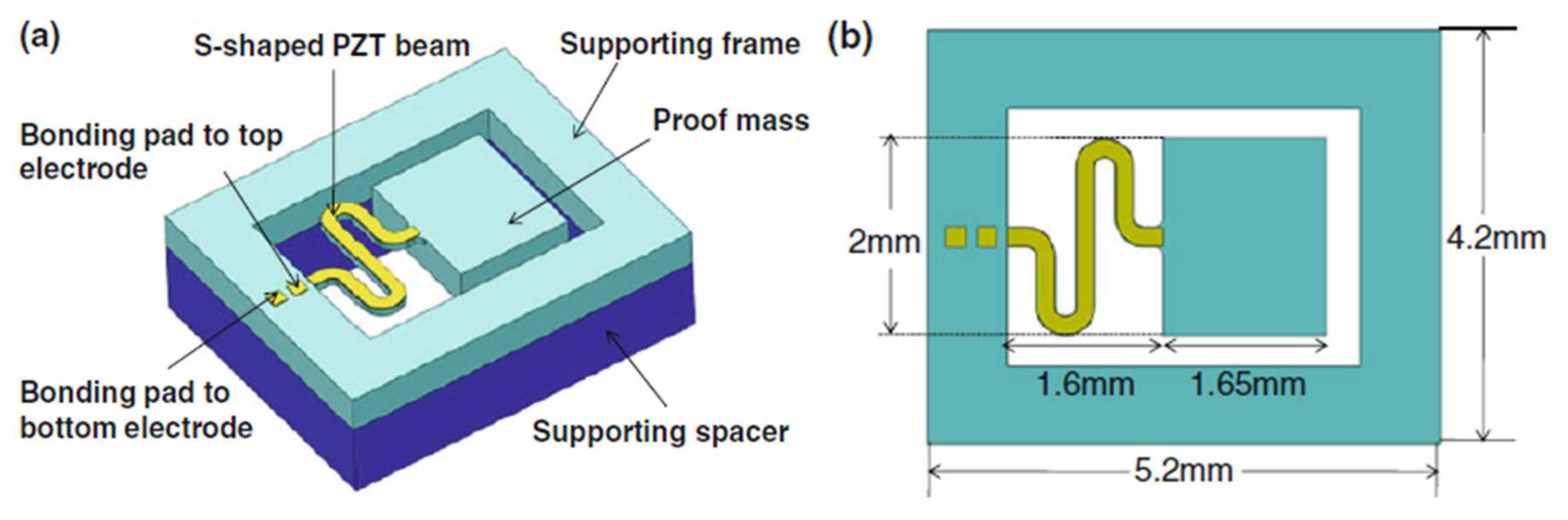
  63. Liu, H.; Lee, C.; Kobayashi, T.; Tay, C.J.; Quan, C. A new S-shaped MEMS PZT cantilever for energy harvesting from low frequency vibrations below 30 Hz. Microsyst. Technol. 2012, 18, 497–506. [Google Scholar] [CrossRef]
  64. Zhang, L.; Lu, J.; Takei, R.; Makimoto, N.; Itoh, T.; Kobayashi, T. S-shape spring sensor: Sensing specific low-frequency vibration by energy harvesting. Rev. Sci. Instrum. 2016, 87, 085005. [Google Scholar] [CrossRef] [PubMed]
  65. Karami, M.A.; Inman, D.J. Electromechanical modeling of the low-frequency zigzag micro-energy harvester. J. Intell. Mater. Syst. Struct. 2011, 22, 271–282. [Google Scholar] [CrossRef]
  66. Kim, I.H.; Jin, S.S.; Jang, S.J.; Jung, H.J. A performance-enhanced energy harvester for low frequency vibration utilizing a corrugated cantilevered beam. Smart Mater. Struct. 2014, 23, 623–626. [Google Scholar] [CrossRef]
  67. Kulah, H.; Najafi, K. Energy scavenging from low-frequency vibrations by using frequency up-conversion for wireless sensor applications. IEEE Sens. J. 2008, 8, 261–268. [Google Scholar] [CrossRef]
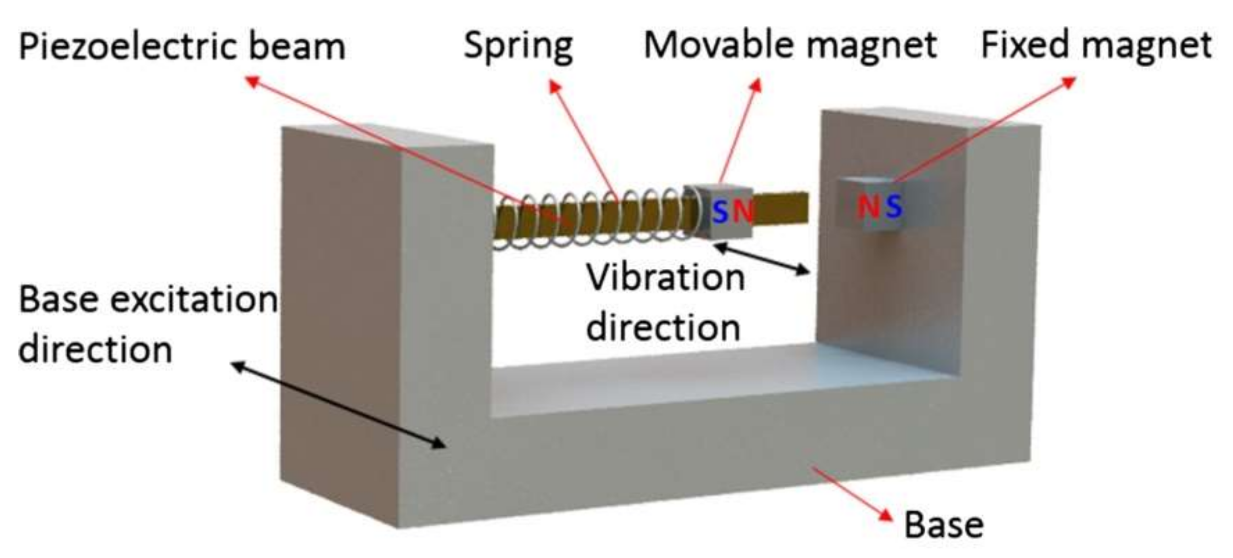
  68. Chen, S.; Ma, L.; Chen, T.; Liu, H.; Sun, L.; Wang, J. Modeling and verification of a piezoelectric frequency-up-conversion energy harvesting system. Microsyst. Technol. 2017, 23, 2459–2466. [Google Scholar] [CrossRef]
  69. Kwon, D.S.; Ko, H.J.; Kim, J. Piezoelectric and electromagnetic hybrid energy harvester using two cantilevers for frequency up-conversion. In Proceedings of the IEEE International Conference on MICRO Electro Mechanical Systems, Las Vegas, NV, USA, 22–26 January 2017. [Google Scholar]
  70. Halim, M.A.; Park, J.Y. A non-resonant, frequency up-converted electromagnetic energy harvester from human-body-induced vibration for hand-held smart system applications. J. Appl. Phys. 2014, 115, 094901. [Google Scholar] [CrossRef]
  71. Halim, M.A.; Park, J.Y. Piezoelectric energy harvester using impact-driven flexible side-walls for human-limb motion. Microsyst. Technol. 2018, 24, 2099–2107. [Google Scholar] [CrossRef]
  72. Jeong, S.W.; Yoo, H.H. Bi-stable cantilevered piezoelectric energy harvester using springs. In Proceedings of the 23rd International Congress on Sound and Vibration: From Ancient to Modern Acoustics, Athens, Greece, 10–14 July 2016; Vogiatzis, K., Kouroussis, G., Crocker, M., Pawelczyk, M., Eds.; International Institute Acoustics & Vibration: Auburn, AL, USA, 2016. [Google Scholar]
  73. Braghin, F.; Mehdipour, I.; Lecis, N.; Galassi, C. Periodic substructure for multi-frequency energy harvesting with single piezoelectric patch. In Active and Passive Smart Structures and Integrated Systems 2016; Park, G., Ed.; Spie-Int Soc Optical Engineering: Bellingham, WA, USA, 2016; Volume 9799. [Google Scholar]
  74. Yang, W.; Towfighian, S. A hybrid nonlinear vibration energy harvester. Mech. Syst. Signal Process. 2017, 90, 317–333. [Google Scholar] [CrossRef]
  75. Wang, X.; Chen, C.; Wang, N.; San, H.; Yu, Y.; Halvorsen, E.; Chen, X. A frequency and bandwidth tunable piezoelectric vibration energy harvester using multiple nonlinear techniques. Appl. Energy 2017, 190, 368–375. [Google Scholar] [CrossRef]
  76. Bao, M.; Yang, H. Squeeze film air damping in mems. Sens. Actuator A Phys. 2007, 136, 3–27. [Google Scholar] [CrossRef]
  77. Schmidt, V.H. Theoretical electrical power output per unit voume of PVF2 and mechanical-to-electrical conversion efficiency as functions of frequency. In Proceedings of the 6th IEEE International Symposium on Applications of Ferroelectrics, Bethlehem, PA, USA, 8–11 June 1986; pp. 538–542. [Google Scholar]
  78. Le, T.T.; Han, J.F.; von Jouanne, A.; Mayaram, K.; Fiez, T.S. Piezoelectric micro-power generation interface circuits. IEEE J. Solid-State Circuits 2006, 41, 1411–1420. [Google Scholar] [CrossRef]
  79. Woo, M.S.; Ahn, J.H.; Eom, J.H.; Hwang, W.S.; Kim, J.H.; Yang, C.H.; Song, G.J.; Hong, S.D.; Jhun, J.P.; Sung, T.H. Study on increasing output current of piezoelectric energy harvester by fabrication of multilayer thick film. Sens. Actuator A Phys. 2018, 269, 524–534. [Google Scholar] [CrossRef]
Figure 1. Schematic of spring–mass–damping system.
Applsci 08 00645 g001
Figure 2. A polycrystalline ferroelectric is before and after poling. Reprinted by permission from Damjanovic.
Applsci 08 00645 g002
Figure 3. Schematic of the PEHs for: (a) a parallel plate electrode system; and (b) an interdigital electrode system. Reprinted by permission from Chidambaram et al., IEEE Trans. Ultrason. Eng. 59, 1624 (2012). Copyright 2012 IEEE.
Applsci 08 00645 g003
Figure 4. Poling direction of: (a) d31 mode; and (b) d33 mode devices in cross section.
Applsci 08 00645 g004
Figure 5. (a) Schematic of S-shaped cantilever PEH; (b) The top view of S-shaped cantilever PEH. Reprinted by permission from Liu et al. Microsyst. Technol. 18, 497 (2012). Copyright 2012 Springer Nature.
Applsci 08 00645 g005
Figure 6. Experimental setup for the dynamic characterization. Reprinted by permission from Liu et al. Microsyst. Technol. 18, 497 (2012). Copyright 2012 Springer Nature.
Applsci 08 00645 g006
Figure 7. Schematic view of the low-frequency PEH design: (a,b) two- and three-spring sensor structures, respectively. Reprinted by permission from Zhang et al. Rev. Sci. Instrum. 87, 085005 (2016). Copyright 2016 AIP Publishing LLC.
Applsci 08 00645 g007
Figure 8. Schematic of the PEH using frequency up-conversion technology. Reprinted by permission from Chen et al. Microsyst. Technol. 23, 2459 (2017). Copyright 2017 Springer Nature.
Applsci 08 00645 g008
Figure 9. The simulated mass displacements of the LFPB and HFPB. Reprinted by permission from Chen et al. Microsyst. Technol. 23, 2459 (2017). Copyright 2017 Springer Nature.
Applsci 08 00645 g009
Figure 10. Configuration of the PEH with an adjustable top stopper. Reprinted by permission from Liu et al. Microsyst. Technol. 18, 497 (2012). Copyright 2012 Springer Nature.
Applsci 08 00645 g010
Figure 11. Nonlinear PEH combining bi-stability and internal resonance. Reprinted by permission from Yang et al. Mech. Syst. Signal Pr. 90, 317 (2017). Copyright 2017 Elsevier.
Applsci 08 00645 g011
Figure 12. Equivalent circuit for a PEH.
Applsci 08 00645 g012
Table 1. Comparison of some parameters of piezoelectric material. The coefficients for piezoelectric polymers are given by thesis [41].
Materialsd31 (pC/N)d33 (pC/N)Kp (%)ɛrTCurie (°C)Reference
PZT-2−60.215247-370
PZT-4−12328958-328
PZT-5A−17137460-365
PZT-5H−27459365-193
PZT-8−3722551-300
(Na0.5K0.5)NbO3-LiTaO3-20036570-[34]
(Na0.5K0.5)NbO3-14838.9606395[35]
[Bi0.5(Na1−x−yKxLiy)0.5]TiO3-23141.01190-[36]
0.69BiFeO–0.04Bi(ZnTi)O–0.27BaTiO (MoOdoped)-14541.0-510[37]
Li0.058(K0.480Na0.535)0.966(Nb0.9Ta0.1)O3(ZnO doped)-272445081395[38]
Bi0.5(Na0.68K0.22Li0.1)0.5TiO3 ((Ba0.90Ca0.10)(Ti0.85Zr0.15)O3 doped)-295-2720-[42]
(Bi0.5Na0.5)TiO3(BaTiO3doped)37180-1557-[43]
((Na0.535K0.48)NbO3(LiNbO3 doped) 150505500470[44]
0.995(K0.5Na0.5)1−xLixNbO3–0.005BiAlO3 18237.55000450[45]
PVDF8~22−24~−34---
P(VDF-TrFE)12−38---
P(VDF-HFP)30−24---
P(VDF-CTFE)-−140---
Table 2. The structure and parameters of PEHs.
StructureMax PowerMax VoltageBandwidth (Hz)Frequency (Hz)Excitation Acceleration (g)Reference
S-shaped cantilever1.117 nW42.1mV-27.40.06[63]
Wavy cantilever-91.8V/g-6.00.1[66]
Flexible sidewall175 µW--4.962[71]
S-shaped cantilever with a stopper2.8nW/g2 (np)16 mV10.123.5–33.60.3[63]
Cantilever attached to the spring2.5 mW15 V61–70.3[72]
Cantilevers with three intrinsic frequencies---41.31
56.85
79.78
-[73]
Parallel-plate-0.733 V100250–3501.5[75]

