An Outdoor Navigation System for Blind Pedestrians Using GPS and Tactile-Foot Feedback

 ,
,  , ,
, ,  ,
,  and
and 
Abstract
:
1. Introduction
- (1)
- Obstacle detection technologies involve complex, continuous, and time-consuming operations; environment scanning requires the user to actively scan the environment. The gathered information must be analyzed before making a decision—constant activity and cognitive effort that reduces walking speed and quickly fatigues the user.
- (2)
- They provide acoustic feedback. Blind people rely on hearing environmental cues for key navigation tasks, such as awareness, orientation, mobility, and safety. A system providing continuous acoustic feedback might distract the user from the environment. While obstacle detection systems typically provide different frequency tones to indicate the distance to an object, localization systems provide spoken voice commands to guide the pedestrian along a path.
- (3)
- Long learning and training times are required to master most navigation assistive systems. Blind people invest non-negligible time to get used to the device and understand fully the system’s feedback, which is certainly frustrating and discouraging.
- (4)
- They are still burdensome and conspicuous as portable or wearable devices, which are essential needs for blind pedestrians.
2. Related Work
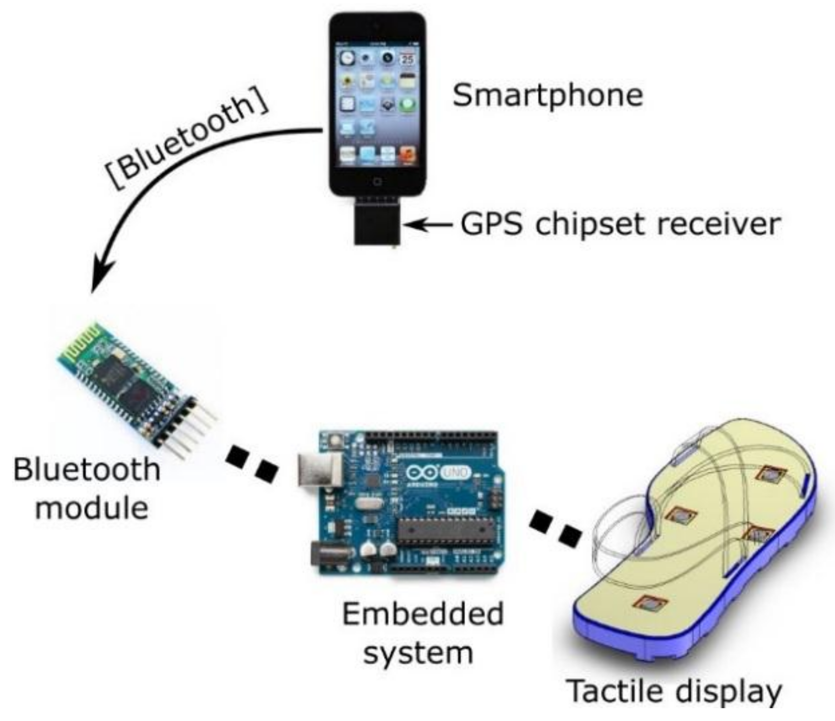
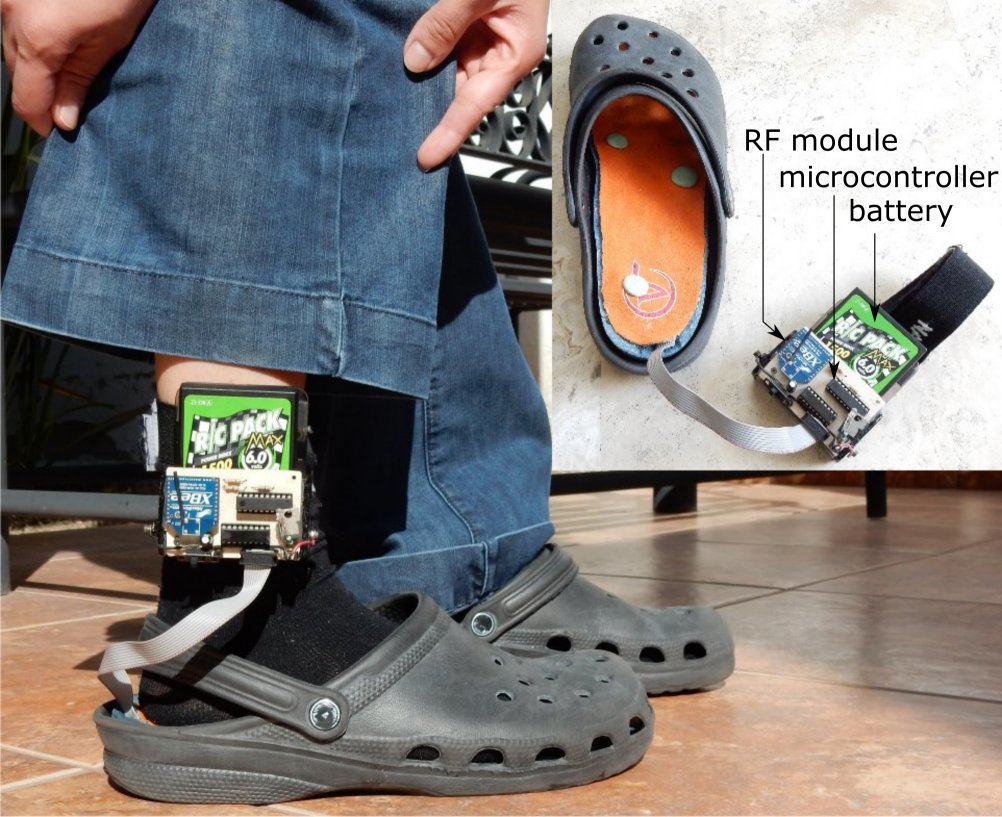
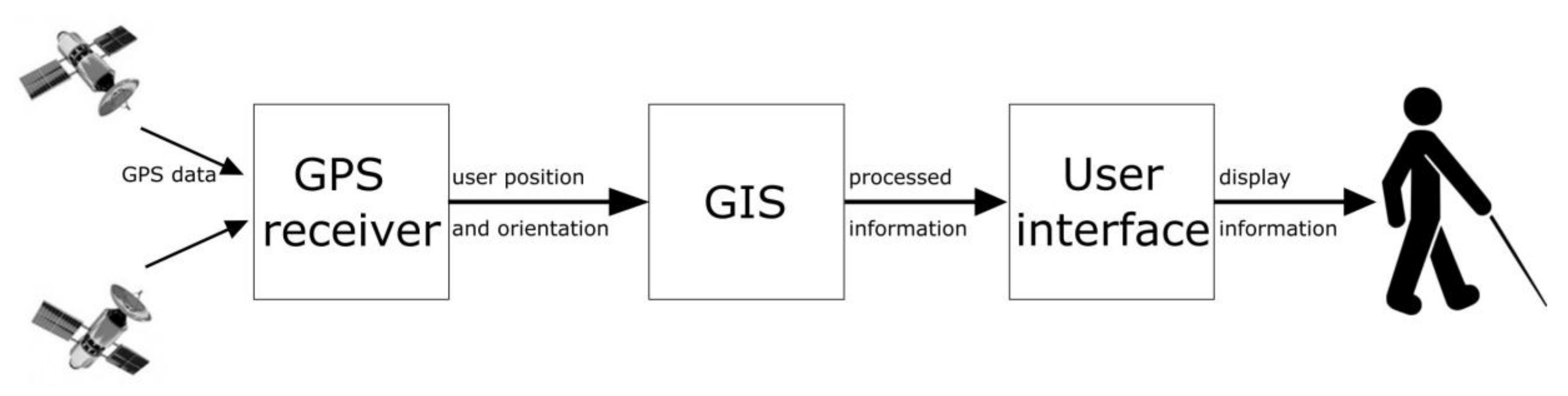
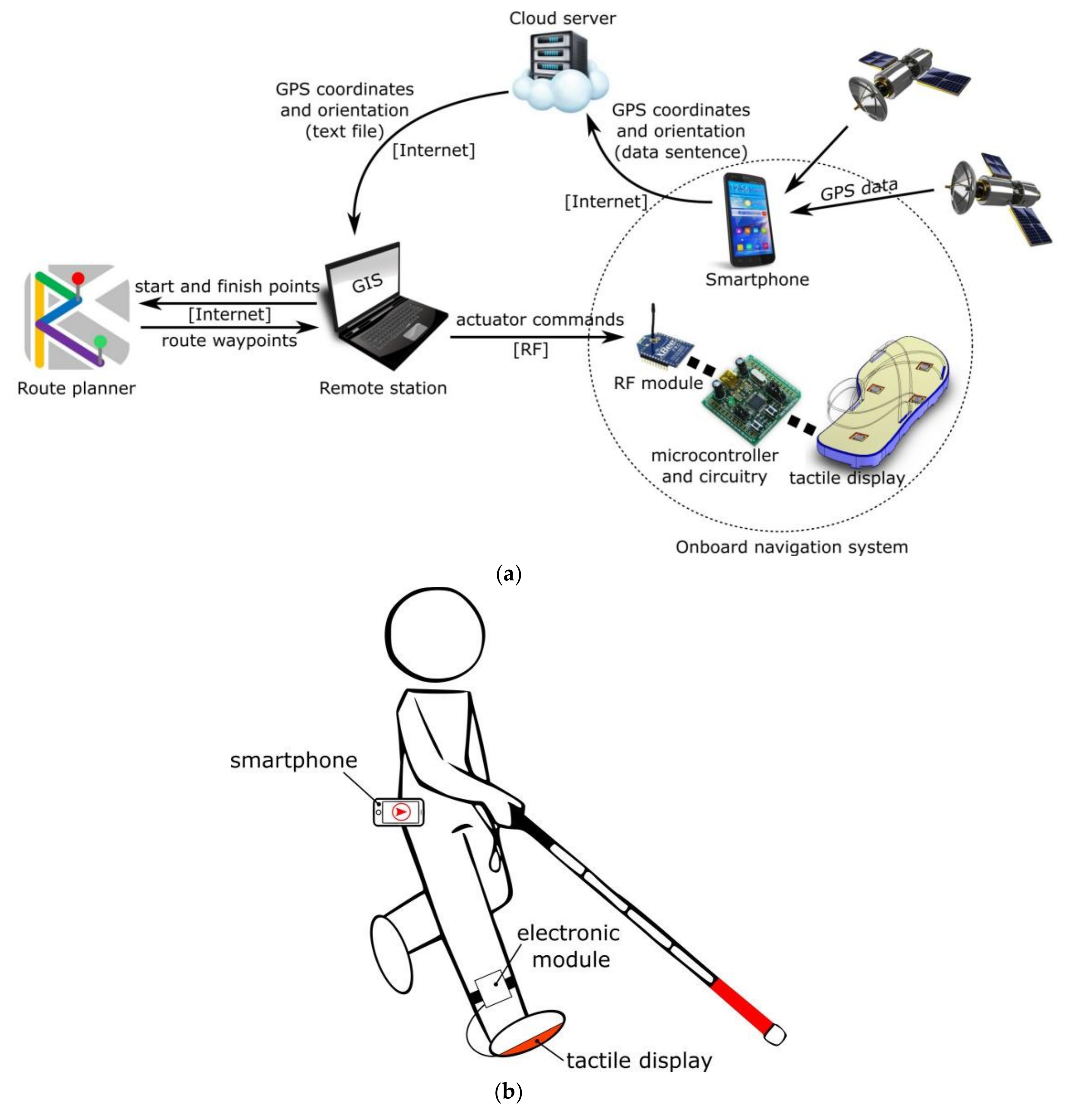
3. System Description
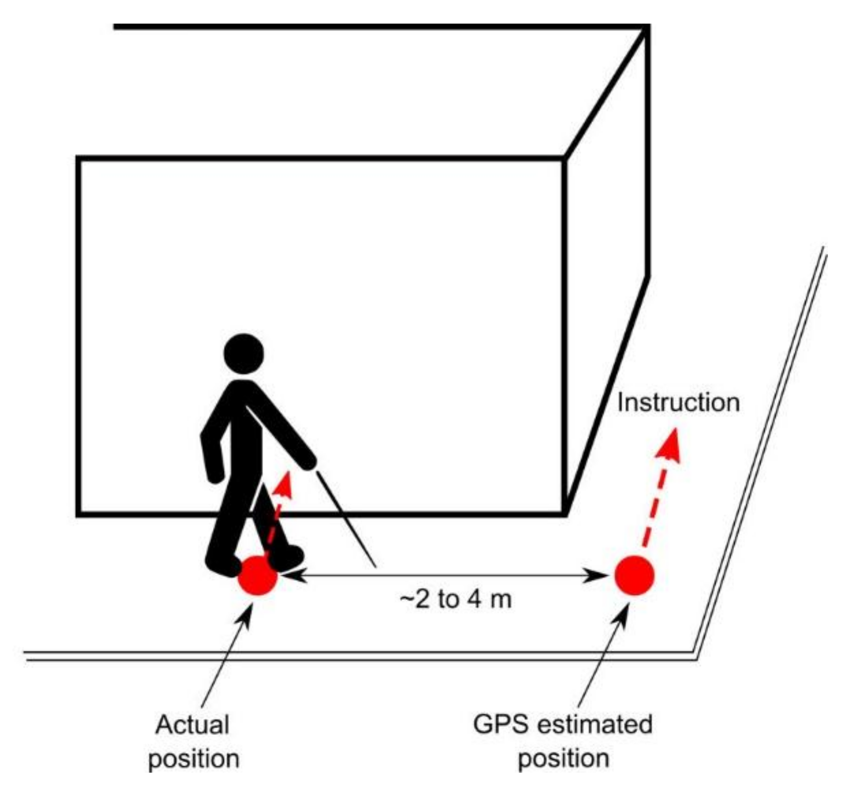
3.1. Localization and Guidance
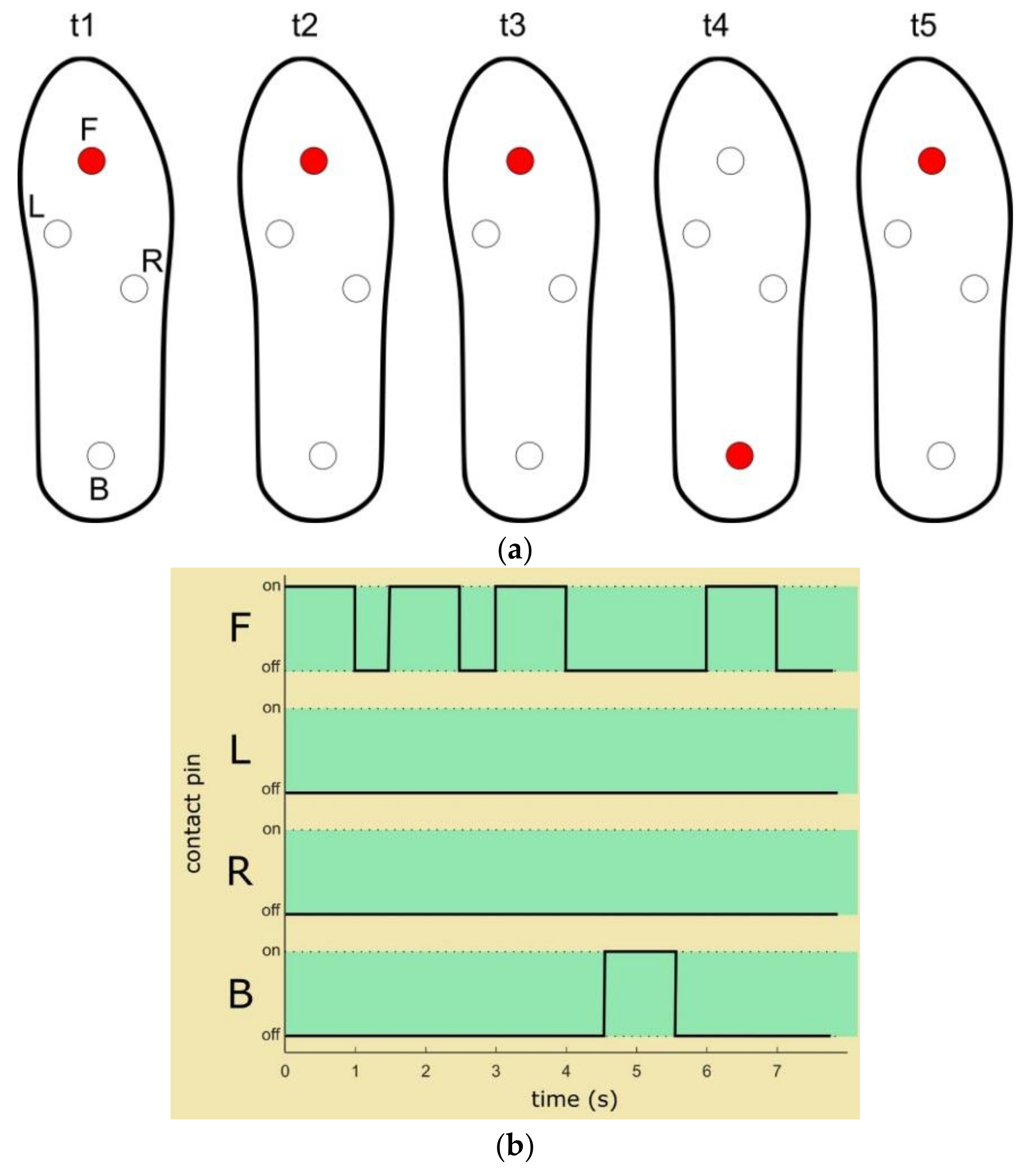
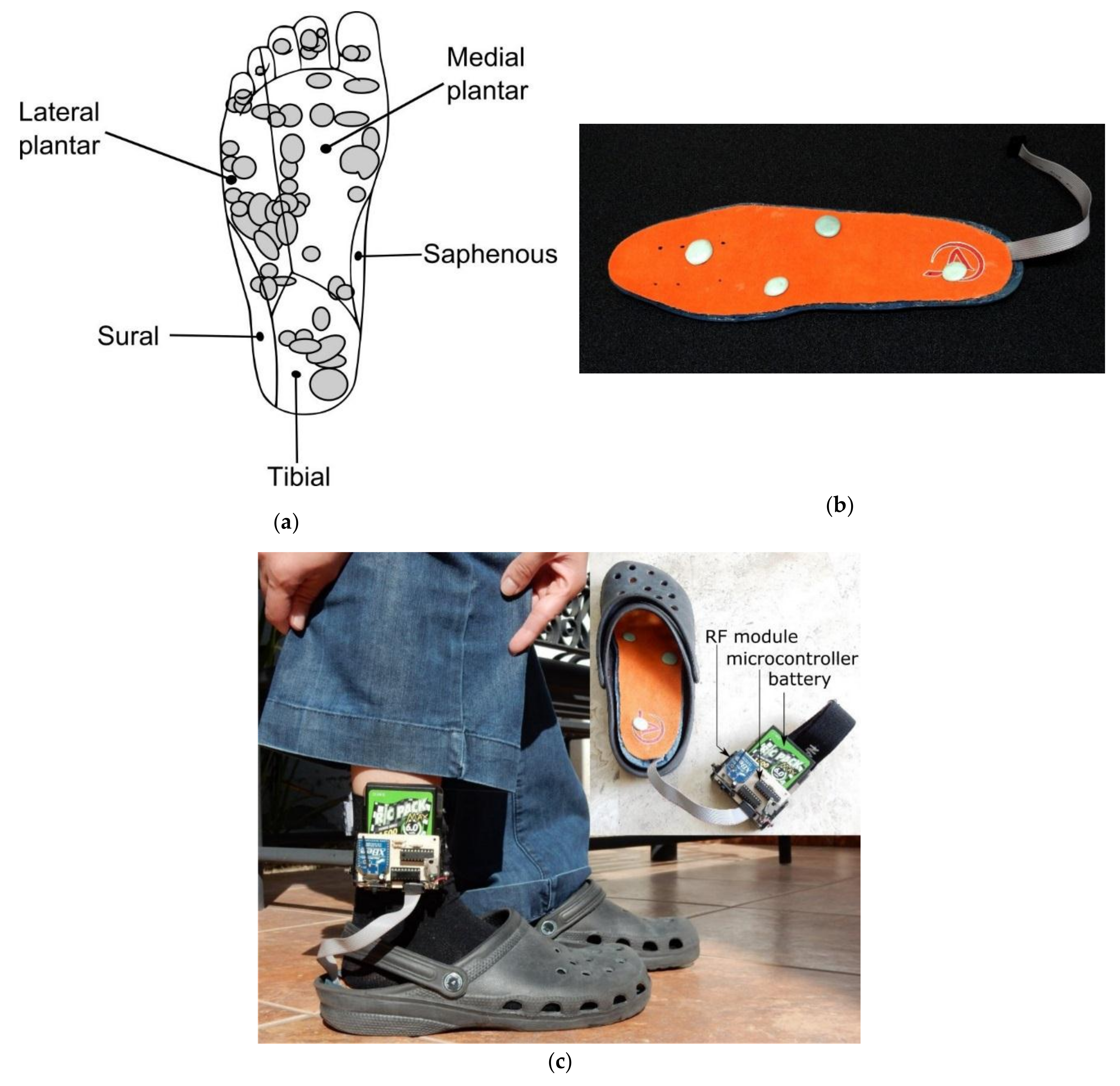
3.2. User Interface
4. Evaluation
4.1. Experiment I: Direction Recognition
4.1.1. Study Participants and Experimental Procedure
4.1.2. Method
4.1.3. Results
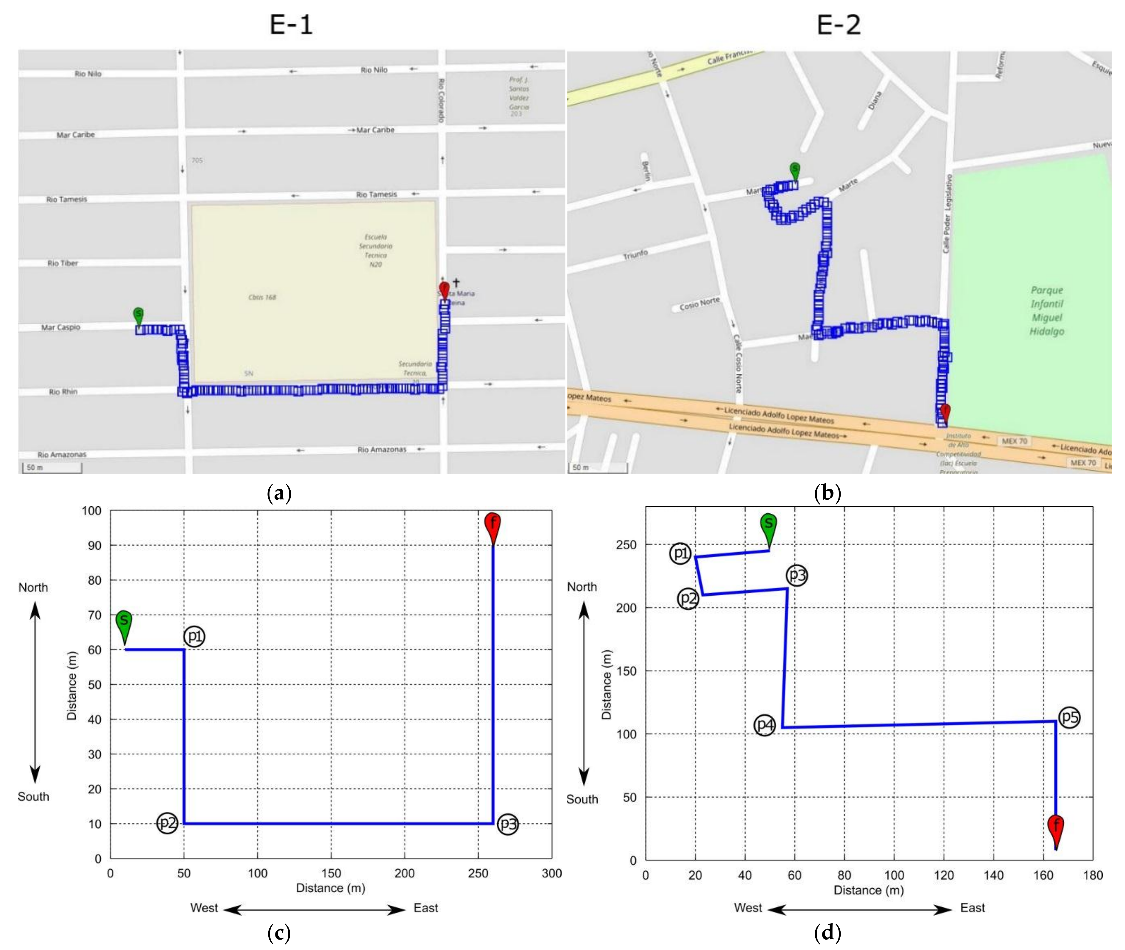
4.2. Experiment II: Outdoor Navigation
4.2.1. Study Participants and Experimental Procedure
4.2.2. Method
4.2.3. Results
5. Conclusions
Author Contributions
Conflicts of Interest
References
- Loomis, J.; Golledge, R.; Klatzky, R.; Speigle, J.; Tietz, J. Personal Guidance System for the Visually Impaired. In Proceedings of the Annual ACM Conference on Assistive Technologies, Marina del Rey, CA, USA, 31 October–1 November1994; pp. 85–91. [Google Scholar] [CrossRef]
- Kay, L. A Sonar Aid to Enhance Spatial Perception of the Blind: Engineering Design and Evaluation. Radio Electron. Eng. 1974, 44, 605–627. [Google Scholar] [CrossRef]
- Pressey, N. Mowat Sensor. Focus 1977, 11, 35–39. [Google Scholar]
- Veelaert, P.; Bogaerts, W. Ultrasonic Potential Field Sensor for Obstacle Avoidance. IEEE Trans. Robot. Autom. 1990, 15, 774–779. [Google Scholar] [CrossRef]
- Hoyle, B.; Waters, D. Mobility AT: The Batcane (UltraCane). In Assistive Technology for Visually Impaired and Blind People; Hersh, M., Johnson, M., Eds.; Springer: London, UK, 2008; pp. 209–229. ISBN 978-1-84628-867-8. [Google Scholar] [CrossRef]
- Farcy, R.; Damaschini, R. Triangulating Laser Profilometer as a Threedimensional Space Perception System for the Blind. Appl. Opt. 1997, 36, 8227–8232. [Google Scholar] [CrossRef] [PubMed]
- Milios, E.; Kapralos, B.; Kopinska, A.; Stergiopoulos, S. Sonification of Range Information for 3-D Space Perception. IEEE Trans. Neural Syst. Rehabil. Eng. 2003, 11, 416–421. [Google Scholar] [CrossRef] [PubMed]
- Pissaloux, E.; Velazquez, R.; Maingreaud, F. A New Framework for Cognitive Mobility of Visually Impaired Users in Using Tactile Device. IEEE Trans. Hum.-Mach. Syst. 2017, 47, 1040–1051. [Google Scholar] [CrossRef]
- Rodriguez, A.; Yebes, J.; Alcantarilla, P.; Bergasa, L.; Almazan, J.; Cela, A. Assisting the Visually Impaired: Obstacle Detection and Warning System by Acoustic Feedback. Sensors 2012, 12, 17476–17496. [Google Scholar] [CrossRef] [PubMed]
- Lee, Y.; Medioni, G. RGB-D Camera Based Wearable Navigation System for the Visually Impaired. Comput. Vis. Image Understand. 2016, 149, 3–20. [Google Scholar] [CrossRef]
- Vlaminck, M.; Hiep, Q.; Hoang, V.; Vu, H.; Veelaert, P.; Philips, W. Indoor Assistance for Visually Impaired People Using a RGB-D Camera. In Proceedings of the IEEE Southwest Symposium on Image Analysis and Interpretation, Santa Fe, NM, USA, 6–8 March 2016; pp. 161–164. [Google Scholar] [CrossRef]
- Hesch, J.; Roumeliotis, S. An Indoor Localization Aid for the Visually Impaired. In Proceedings of the IEEE International Conference on Robotics and Automation, Roma, Italy, 10–14 April 2007; pp. 3545–3551. [Google Scholar] [CrossRef]
- Jain, D. Path-Guided Indoor Navigation for the Visually Impaired Using Minimal Building Retrofitting. In Proceedings of the International ACM SIGACCESS Conference on Computers & Accessibility, Rochester, NY, USA, 20–22 October 2014; pp. 225–232. [Google Scholar] [CrossRef]
- Kulyukin, V.; Gharpure, C.; Nicholson, J.; Pavithran, S. RFID in Robot-Assisted Indoor Navigation for the Visual Impaired. In Proceedings of the IEEE/RSJ International Conference on Intelligent Robots and Systems, Sendai, Japan, 28 September–2 October 2004; pp. 353–357. [Google Scholar] [CrossRef]
- Ivanov, R. Indoor Navigation System for the Visually Impaired. In Proceedings of the International Conference on Computer Systems and Technologies, Sofia, Bulgaria, 17–18 June 2010; pp. 143–149. [Google Scholar] [CrossRef]
- Ando, B.; Baglio, S.; Lombardo, C.O.; Marletta, V. Smart Multisensor Strategies for Indoor Localization. In Mobility of Visually Impaired People: Fundamentals and ICT Assistive Technologies; Pissaloux, E., Velazquez, R., Eds.; Springer International Publishing: Basel, Switzerland, 2018; pp. 585–595. ISBN 978-3-319-54444-1. [Google Scholar] [CrossRef]
- Alvarez, Y.; Las Heras, F. ZigBee-Based Sensor Network for Indoor Location and Tracking Applications. IEEE Lat. Am. Trans. 2016, 14, 3208–3214. [Google Scholar] [CrossRef]
- Muñoz, J.; Li, B.; Rong, X.; Xiao, J.; Tian, Y.; Arditi, A. Demo: Assisting Visually Impaired People Navigate Indoors. In Proceedings of the International Joint Conference on Artificial Intelligence, New York, NY, USA, 9–15 July 2016; pp. 4260–4261. [Google Scholar]
- Velazquez, R. Wearable Assistive Devices for the Blind. In Wearable and Autonomous Biomedical Devices and Systems for Smart Environment: Issues and Characterization; Lay-Ekuakille, A., Mukhopadhyay, S.C., Eds.; LNEE, 75; Springer: Berlin/Heidelberg, Germany, 2010; pp. 331–349. ISBN 978-3-642-15687-8. [Google Scholar] [CrossRef]
- Pissaloux, E.; Velazquez, R. On Spatial Cognition and Mobility Strategies. In Mobility of Visually Impaired People: Fundamentals and ICT Assistive Technologies; Pissaloux, E., Velazquez, R., Eds.; Springer International Publishing: Basel, Switzerland, 2018; pp. 137–166. ISBN 978-3-319-54444-1. [Google Scholar] [CrossRef]
- Collins, C. On Mobility Aids for the Blind. In Electronic Spatial Sensing for the Blind; Warren, D., Strelow, E., Eds.; Springer: Dordrecht, The Netherlands, 1985; pp. 35–64. ISBN 978-90-247-3238-8. [Google Scholar] [CrossRef]
- Loomis, J. Digital Map and Navigation System for the Visually Impaired; Unpublished Manuscript; Department of Psychology, University of California: Santa Barbara, CA, USA, 1985. [Google Scholar]
- Brusnighan, D.; Strauss, M.; Floyd, J.; Wheeler, B. Orientation Aid Implementing the Global Positioning System. In Proceedings of the IEEE Annual Northeast Bioengineering Conference, Boston, MA, USA, 27–28 March 1989; pp. 33–34. [Google Scholar] [CrossRef]
- Sendero Group LLC. Davis, CA, USA. Available online: http://www.senderogroup.com/ (accessed on 15 March 2018).
- Humanware Group. Drummondville, Quebec, Canada. Available online: www.humanware.com/ (accessed on 15 March 2018).
- Dawidson, E. Pedestrian Navigation in Stockholm, How Local Data Together with Advanced Positioning Techniques Can Be Used for Detailed Routing. In Proceedings of the ITS World Congress, Stockholm, Sweden, 21–25 September 2009; pp. 1–8. [Google Scholar]
- Koskinen, S.; Virtanen, A. Navigation System for the Visually Impaired Based on an Information Server Concept. In Proceedings of the Mobile Venue, Athens, Greece, 14–17 March 2004; pp. 1–6. [Google Scholar]
- Gaunet, F. Verbal Guidance Rules for a Localized Wayfinding Aid Intended for Blind-Pedestrians in Urban Areas. Univers. Access Inf. Soc. 2006, 4, 338–353. [Google Scholar] [CrossRef]
- Golledge, R.; Klatzky, R.; Loomis, J.; Speigle, J.; Tietz, J. A Geographical Information System for a GPS Based Personal Guidance System. Int. J. Geogr. Inf. Syst. 1998, 12, 727–749. [Google Scholar] [CrossRef]
- Matsuda, K.; Kondo, K. Towards a Navigation System for the Visually Impaired using 3D Audio. In Proceedings of the IEEE Global Conference on Consumer Electronics, Kyoto, Japan, 11–14 October 2016; pp. 1–2. [Google Scholar] [CrossRef]
- Holland, S.; Morse, D.; Gedenryd, H. AudioGPS: Spatial Audio Navigation in a Minimal Attention Interface. Pers. Ubiquitous Comput. 2002, 6, 253–259. [Google Scholar] [CrossRef]
- Guerrero, L.A.; Vasquez, F.; Ochoa, S. An Indoor Navigation System for the Visually Impaired. Sensors 2012, 12, 8236–8258. [Google Scholar] [CrossRef] [PubMed]
- Zelek, J. Seeing by Touch (Haptics) for Wayfinding. Int. Congr. Ser. 2005, 1282, 1108–1112. [Google Scholar] [CrossRef]
- Pielot, M.; Poppinga, B.; Heuten, W.; Boll, S. PocketNavigator: Studying Tactile Navigation Systems In-Situ. In Proceedings of the SIGCHI Conference on Human Factors in Computing Systems, Austin, TX, USA, 5–10 May 2012; pp. 3131–3140. [Google Scholar] [CrossRef]
- Jacob, R.; Mooney, P.; Corcoran, P.; Winstanley, A. Integrating Haptic Feedback to Pedestrian Navigation Applications. In Proceedings of the GIS Research UK Annual Conference, Portsmouth, UK, 27–29 April 2011; pp. 20–210. [Google Scholar]
- Pielot, M.; Boll, S. Tactile Wayfinder: Comparison of Tactile Waypoint Navigation with Commercial Pedestrian Navigation Systems. In Pervasive Computing; Floréen, P., Krüger, A., Spasojevic, M., Eds.; LNCS, 6030; Springer: Berlin/Heidelberg, Germany, 2010; pp. 76–93. ISBN 978-3-642-12653-6. [Google Scholar] [CrossRef]
- Schirmer, M.; Hartmann, J.; Bertel, S.; Echtler, F. Shoe me the Way: A Shoe-Based Tactile Interface for Eyes-Free Urban Navigation. In Proceedings of the International Conference on Human-Computer Interaction with Mobile Devices and Services, Copenhagen, Denmark, 24–27 August 2015; pp. 327–336. [Google Scholar] [CrossRef]
- Spiers, A.; Dollar, A. Outdoor Pedestrian Navigation Assistance with a Shape Changing Haptic Interface and Comparison with a Vibrotactile Device. In Proceedings of the IEEE Haptics Symposium, Philadelphia, PA, USA, 8–11 April 2016; pp. 34–40. [Google Scholar] [CrossRef]
- Meier, A.; Matthies, D.; Urban, B.; Wettach, R. Exploring Vibrotactile Feedback on the Body and Foot for the Purpose of Pedestrian Navigation. In Proceedings of the International Workshop on Sensor-based Activity Recognition and Interaction, Rostock, Germany, 25–26 June 2015. Article 11. [Google Scholar] [CrossRef]
- Gutierrez-Martinez, J.M.; Castillo-Martinez, A.; Medina-Merodio, J.A.; Aguado-Delgado, J.; Martinez-Herraiz, J.J. Smartphones as a Light Measurement Tool: Case of Study. Appl. Sci. 2017, 7, 616. [Google Scholar] [CrossRef]
- OpenStreetMap Project. Available online: www.openstreetmap.org/ (accessed on 15 March 2018).
- YOURS map and router-finder. Available online: http://yournavigation.org/ (accessed on 15 March 2018).
- Kennedy, P.M.; Inglis, J.T. Distribution and Behaviour of Glabrous Cutaneous Receptors in the Human Foot Sole. J. Physiol. 2002, 538, 995–1002. [Google Scholar] [CrossRef] [PubMed]
- Velazquez, R.; Bazan, O.; Varona, J.; Delgado-Mata, C.; Gutierrez, C.A. Insights into the Capabilities of Tactile-Foot Perception. Int. J. Adv. Robot. Syst. 2012, 9, 1–11. [Google Scholar] [CrossRef]
- Velazquez, R.; Pissaloux, E.; Lay-Ekuakille, A. Tactile-Foot Stimulation Can Assist the Navigation of People with Visual Impairment. Appl. Bionics Biomech. 2015, 2015. [Google Scholar] [CrossRef] [PubMed]
- Velazquez, R.; Varona, J.; Rodrigo, P. Computer-Based System for Simulating Visual Impairments. IETE J. Res. 2016, 62, 833–841. [Google Scholar] [CrossRef]
- Browning, R.; Baker, E.; Herron, J.; Kram, R. Effects of Obesity and Sex on the Energetic Cost and Preferred Speed of Walking. J. Appl. Physiol. 2006, 100, 390–398. [Google Scholar] [CrossRef] [PubMed]
- BBC World News. Horizons Series—Sharper Senses. Episode 5 Clip 3: When in Doubt, Follow Your Feet. Available online: http://www.bbc.com/specialfeatures/horizonsbusiness/seriessix/sharper-senses/ (accessed on 15 March 2018).


| Answered (%) | ||||||
|---|---|---|---|---|---|---|
| Forward | Backward | Left | Right | Stop | ||
| Presented | Forward | 100 | 0 | 0 | 0 | 0 |
| Backward | 2.22 | 97.78 | 0 | 0 | 0 | |
| Left | 0 | 0 | 88.89 | 11.11 | 0 | |
| Right | 1.67 | 1.67 | 6.66 | 90 | 0 | |
| Stop | 0 | 0 | 0 | 0 | 100 | |
| E-1 (380 m) | E-2 (420 m) | |
|---|---|---|
| Subject A | 320 s | 381 |
| Subject B | 334 s | 389 |
| Difference | +4.4% (B) | +2.1% (B) |
| E-1 | s-p1 | p1-p2 | p2-p3 | p3-f |
|---|---|---|---|---|
| Subject A | 97.1% | 99.4% | 99.1% | 96.2% |
| Subject B | 96.2% | 98% | 99.5% | 97.5% |
| Difference | +0.9% (A) | +1.4% (A) | +0.4% (B) | +1.3 (B) |
| E-2 | s-p1 | p1-p2 | p2-p3 | p3-p4 | p4-p5 | p5-f |
|---|---|---|---|---|---|---|
| Subject A | 95.2% | 92.3% | 95.2% | 98.6% | 93.5% | 98% |
| Subject B | 94.7% | 96.7% | 95.4% | 99.8% | 98.7% | 98.3% |
| Difference | +0.5% (A) | +4.4% (B) | +0.2% (B) | +1.2% (B) | +5.2% (B) | +0.3% (B) |
© 2018 by the authors. Licensee MDPI, Basel, Switzerland. This article is an open access article distributed under the terms and conditions of the Creative Commons Attribution (CC BY) license (http://creativecommons.org/licenses/by/4.0/).
Share and Cite
Velázquez, R.; Pissaloux, E.; Rodrigo, P.; Carrasco, M.; Giannoccaro, N.I.; Lay-Ekuakille, A. An Outdoor Navigation System for Blind Pedestrians Using GPS and Tactile-Foot Feedback. Appl. Sci. 2018, 8, 578. https://doi.org/10.3390/app8040578
Velázquez R, Pissaloux E, Rodrigo P, Carrasco M, Giannoccaro NI, Lay-Ekuakille A. An Outdoor Navigation System for Blind Pedestrians Using GPS and Tactile-Foot Feedback. Applied Sciences. 2018; 8(4):578. https://doi.org/10.3390/app8040578
Chicago/Turabian StyleVelázquez, Ramiro, Edwige Pissaloux, Pedro Rodrigo, Miguel Carrasco, Nicola Ivan Giannoccaro, and Aimé Lay-Ekuakille. 2018. "An Outdoor Navigation System for Blind Pedestrians Using GPS and Tactile-Foot Feedback" Applied Sciences 8, no. 4: 578. https://doi.org/10.3390/app8040578
APA StyleVelázquez, R., Pissaloux, E., Rodrigo, P., Carrasco, M., Giannoccaro, N. I., & Lay-Ekuakille, A. (2018). An Outdoor Navigation System for Blind Pedestrians Using GPS and Tactile-Foot Feedback. Applied Sciences, 8(4), 578. https://doi.org/10.3390/app8040578