Abstract
With the development of renewable energy, energy substitution technology has been applied to many fields. This research suggests that solar energy, as renewable energy, takes the place of conventional energy: a floor radiant heating system driven by solar energy is combined with a photovoltaic floor radiant heating system, and the photothermal floor radiant heating system has been proposed and investigated in this study. This research also designs a fuzzy PID (Proportion, Integration, Differentiation) control system to control the indoor temperature within the set range precisely. In this paper, the proposed floor radiant heating system has been tested and analyzed. The experimental results show that the inhomogeneity of the indoor floor surface temperature distribution is larger than that of other places, and the standard deviation of the indoor floor surface temperature can reach 1.87 °C. The standard deviation was approximately 0.36 °C at 0.6 m, 1.2 m and 1.8 m, which indicates this is suitable for habitation. Three kinds of floor radiant heating systems were compared and analyzed to demonstrate the advantage of the proposed floor radiant heating system. The calculation method of the heating system was proposed and applied to the actual heating system in this paper. The proposed floor radiant heating system is a highly efficient and environmental protection system that can be used for heating extensive areas to realize the objective of energy saving and emission reduction.
1. Introduction
Floor radiant heating systems have become increasingly popular. These systems have the advantages of being comfortable and healthy, and they have a long-life span and energy savings compared with traditional heating systems. A comparison and analysis of the performance of different low-temperature radiant heating systems on walls, ceilings and floors were conducted by Bojić et al. They found that floor heating is the best method, with low energy consumption and operating costs [1]. However, a traditional floor heating system generally relies on the burning of fossil fuels. First, serious haze has been caused by traditional systems. Second, the system produces hot water at higher temperatures, which affects the comfort level, wastes energy and shortens the life span of the hot water pipes.
Solar energy is a clean renewable energy that has received increasing attention. Many countries regard the development of solar energy utilization technologies as important for sustainable development and consider that a floor radiant heating system driven by solar energy is the best form of heating. However, the existing floor radiant heating system driven by solar energy requires additional heating due to the insufficient stability of solar energy, which is readily affected by season, location, climate and other factors. Many scholars have regarded photovoltaic and photothermal floor radiant heating system technology as a research hot spot and have applied it to heating systems. Izquierdo et al. conducted a series of trials on the heating capacity of photovoltaic heat pumps. Photovoltaic systems generate electricity and store it in the battery. The inverter supplies electricity to the pump. The system supplies hot water to the floor radiant system [2,3]. A combination system with a photovoltaic and thermal system and a ground source heat pump was discussed and evaluated by Jeong et al. [4]. The average seasonal performance of the combination system improved by almost 55.3% compared with the conventional system. The application of a ground source heat pump system coupled with a radiator and radiant floor heating systems was put forward by Sarbu et al. [5]. These authors discussed the coefficient of performance and CO2 emissions of different heating systems in terms of thermal comfort, energy consumption and environmental impact. Sebarchievici and Sarbu [6] also conducted a series experiments to test the performance of the ground-coupled heat pump system in different operating modes. The main performance energy efficiency and CO2 emissions were tested and analyzed to show the advantage of the operational system. Dupeyra et al. [7] studied the performance of photovoltaic-thermal (PVT) hybrid collectors as part of a solar thermal system. The application of efficient PVT collectors is preferable to conventional PV and solar thermal components from a potential energy savings aspect. A model was developed by Herrando et al. [8] to evaluate the performance of hybrid PVT systems for the provision of electricity and hot water. It was demonstrated that the configuration of the PVT system enhanced its thermal and electrical characteristics observably. The combination of a photovoltaic and photothermal system was proposed by the authors in an earlier study. Solar power was used to supply power to the system or an external device, and solar heat was used to generate heat. Consequently, the energy-saving effect and economic efficiency of the solar system improved [9].
The control strategy of a heating system has also been the focus of extensive research. An accurate mathematical model is required to set parameters in the traditional PID (Proportion, Integration, Differentiation) temperature controller in which the coefficient of proportion, integration and differentiation , , are generally fixed. Because the coefficient is not easy to adjust online, the optimal temperature control effect is difficult to achieve in the temperature control system with large inertia and serious hysteresis [10]. Some performance indices were investigated by Montoya-Marquez et al. [11] for a medium temperature flat plate solar collector in an experimental system. Solar radiation was simulated by using a PID controller that considered two conditions of the absorber temperature to achieve suitable and stable conditions. Greater parametric regulation through PID controllers, which can control the calculated values, was proposed by Valíček et al. [12]. These values were calculated in a revised method, and the calculation results achieved an increase in boiler efficiency and power output. The air-handling unit is one of the most complicated pieces of equipment in an HVAC (Heating, Ventilating and Air Conditioning) system, of which the control system is the most crucial for maintaining indoor comfort conditions with low energy consumption. Moradi et al. [13] designed a PID fuzzy controller that guaranteed robust performance against model-based parametric uncertainties compared with other controllers. Chao et al. [14] advocated the equivalence between fuzzy PID controllers and conventional PID controllers. Other optimization algorithms can be used in more complex temperature control systems. For example, a BP (Back Propagation) neural network and fuzzy PID algorithm were combined to predict temperature by D Xia et al. [15]. The precise control of temperature was realized through Smith estimation control and fuzzy PID, which can be better used in an electric boiler temperature control system according to Gu et al. [16].
In this paper, a traditional floor radiant heating system will be reformed, optimized and further improved to meet the requirements of human comfort and energy saving. A floor radiant heating system based on the energy substitution technology will be proposed and the design, experimental test and analysis will also be carried out to verify the comfort and energy saving of the proposed system. Three kinds of floor radiant heating systems driven by solar energy are also discussed and compared in this paper.
2. Heating System Design
The design idea of this system is the formation of a dual-system coordinated operation that combines a photothermal floor radiant heating system and a photovoltaic floor radiant heating system. In the photothermal floor radiant heating system, a solar thermal collector converts solar energy into heat energy and then heats the ground through hot water pipes that are laid in the floor. In the photovoltaic floor radiant heating system, the AC heating cables that are laid in the floor are heated by a photovoltaic power system to supply heat energy to the room.
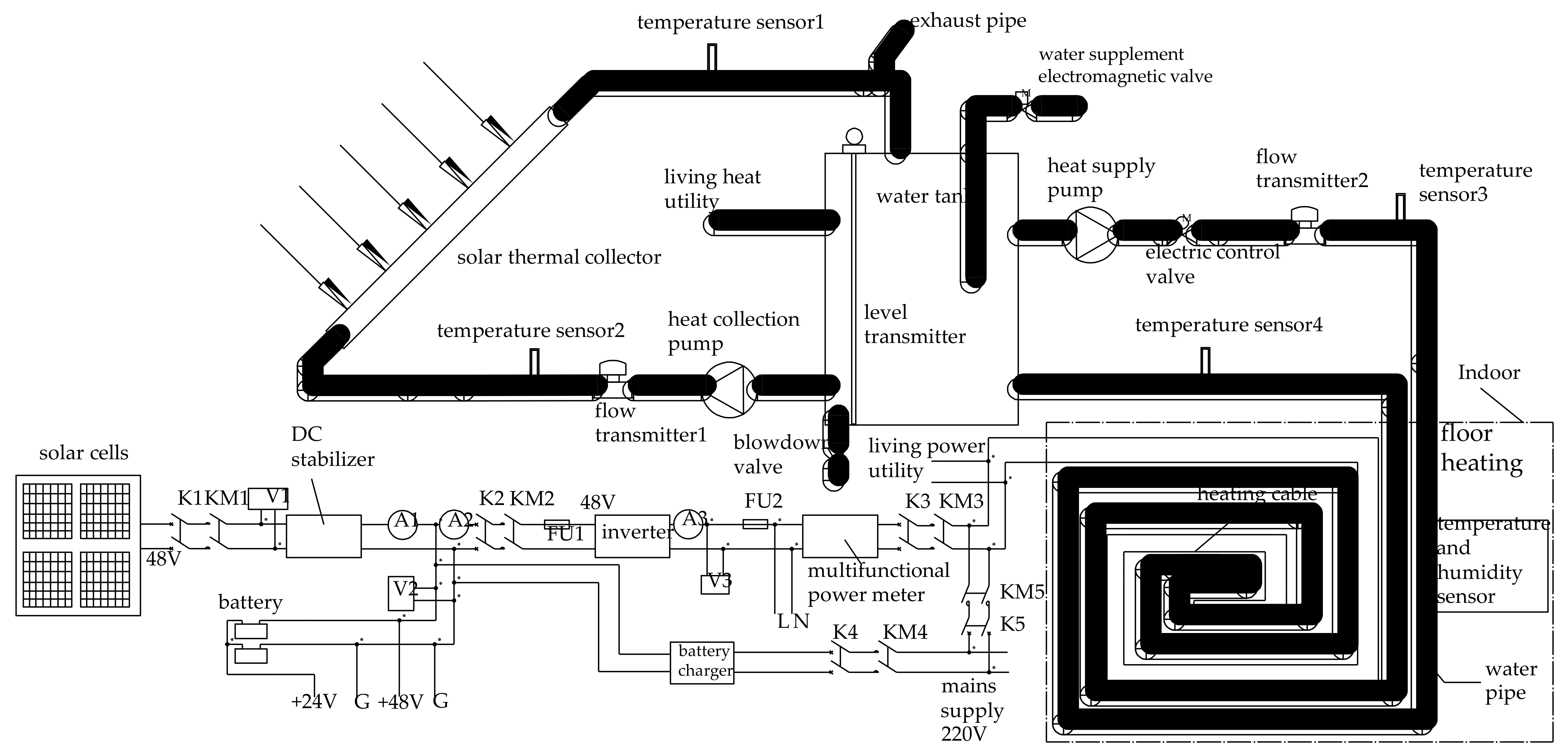
The overall design of the system is shown in Figure 1. The solid line in bold and black is the photothermal floor radiant heating system, and the single solid line is the photovoltaic floor radiant heating system (Figure 1). AC heating cables and water pipes are intertwined and laid evenly in the floor of the room, which has a temperature and humidity sensor. The room temperature can be set and controlled.

Figure 1.
The overall design of the system.
In the photothermal floor radiant heating system, a solar thermal collector heats the water, which is circulated by the heat collection pump in the water tank. Another circuit of the water tank is the indoor hot water, which is circulated by the heat supply pump. The controller collects the indoor temperature signal and adjusts the opening of the electric control valve on the heating circuit by the fuzzy PID algorithm according to the temperature setting value. The heat collection circuit and the heat supply circuit are equipped with temperature sensors and flow transmitters, respectively, for collecting and monitoring the temperature, flow and energy data. The level transmitter, which helps the controller to determine whether to start the water supplement electromagnetic valve, is installed in the water tank. The top of the water tank is equipped with an exhaust pipe to maintain the normal pressure of the water tank. The bottom of the water tank is equipped with a blowdown valve for drainage, which can ensure long-term stability.
In the photovoltaic floor radiant heating system, solar cells convert solar energy into electricity, which is delivered to the inverter through a DC stabilizer. The inverter converts the DC 48 V to AC 220 V to supply the AC heating cables. Solar cells also provide DC 48 V and DC 24 V for the control system and the battery. Diodes that prevent battery reverse charging of the solar cells are installed in the DC stabilizer. The supply mains AC 220 V can supply the heating cables directly and charge the battery through the battery charger to ensure battery life in the case of a shortage of battery power. Using night valley electricity to charge the battery and run the heating system in the daytime is another method of energy saving. The current sensors (A1~A3) and voltage sensors (V1~V3) in the power supply circuit are used for the monitoring of current and voltage. The monitor data are used to judge whether the system is operating normally. The entire photovoltaic power supply circuit is equipped with various circuit breakers (K1~K5), contactors (KM1~KM5) and fuses (FU1~FU2) for remote, automatic and manual control.
A fuzzy PID controller that can monitor and control the entire heating system is designed in this system. The controller contains DO, AI, and AO ports, a power supply port and an RS485 communication port as shown in Figure 2. DO ports output digital instructions to control the on-off operation of the corresponding contactors. Each indicator light that corresponds to the contactor shows the on-off state. The power supply of some contactor coils mainly originates from the battery (DC 48 V) and inverter (AC 220 V). It should be noted that the power supply of the KM4 and KM5 coils is provided by the mains AC 220 V because KM4 and KM5 control the charging of the battery and the supply of the heating cables from the main supply as shown in Figure 1. This part of the power supply needs to be separated from the photovoltaic power generation system to ensure that the system can be started in the event of a lack of solar energy for a long time. AI ports are used to collect analog signals, including the AC and DC voltage and current signals, level transmitter signals, indoor temperature and humidity signals, opening signals of the electric control valve, and temperature and flow signals in the heat collection circuit and the heating supply circuit. The AO1 port is used to output the opening command of the electric control valve. The controller collects and monitors the running times of the photothermal floor radiant heating system and the photovoltaic floor radiant heating system. The power supply port provides DC 24 V from the battery for the controller and the touch screen.
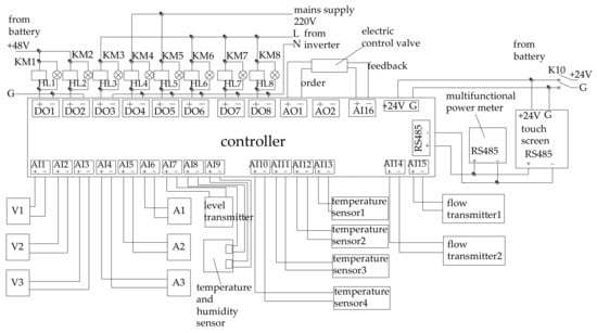
Figure 2.
Schematic diagram of electrical control 1.
The controller, touch screen and multifunctional power meter exchange and share the data through the RS485 communication port. The various collected values of the entire system are monitored on the touch screen that can accept user’s instructions for valve opening control and contactor on-off control. K10 is a DC circuit breaker that can be applied to a manual switch for the power circuit of the control system.
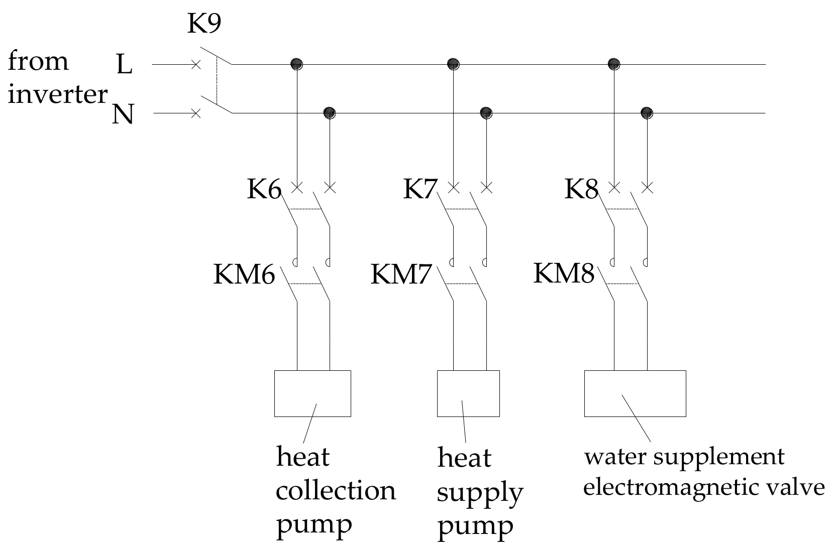
As shown in Figure 3, the inverter provides AC 220 V for the heat collection pump, the heat supply pump and the water supplement electromagnetic valve. K9 is the total AC circuit breaker. K6~K8 are the AC circuit breakers on each branch. KM6~KM8 are the AC contactors on each branch. When one of the KM6~KM8 coils is energized, the corresponding contactor will be closed and the corresponding equipment will be maintained with the power supply. Under normal operation, circuit breakers K1~K10 should be closed and the system can be controlled by the touch screen remotely. In case of emergency, the operation of the devices will be immediately stopped by the circuit breakers.

Figure 3.
Schematic diagram of electrical control 2.
3. Fuzzy PID Control System Design
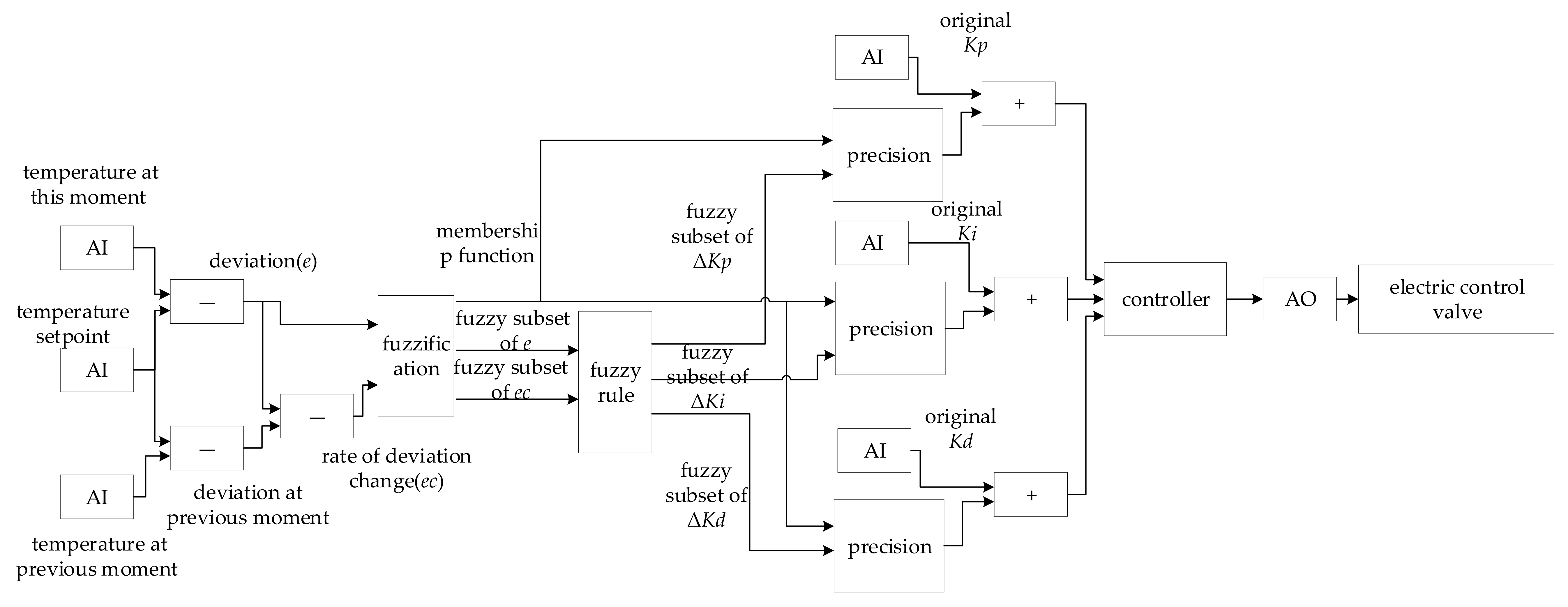
The design of the control strategy is especially important because of the dual system coordinated operation. The fuzzy PID algorithm is used to optimize , , in the controller. From the fuzzy PID controller model shown in Figure 4, the temperature deviation and temperature deviation gradient can be received by collecting the temperature set point and the indoor temperature (at this time and in the previous moment). The fuzzy subset of input after obfuscation can be obtained from and , and then the fuzzy subset of , , can be obtained after fuzzy rules have been applied. Finally, the precise value can be obtained after the precision process. The new control parameter can be obtained by adding the precise value to the , , of traditional PID controllers to participate in regulation. In addition, the AO1 signal can be outputted to the electric control valve to change its opening. The equation of the PID controller parameter after fuzzy rule setting would be (Equation (1)):
where:
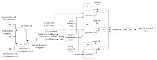
Figure 4.
Fuzzy PID controller model.
- , , represent the final parameter value of the PID controller
- , , represent the initial parameter value of the PID controller
- , , represent the parameter revision value of the PID controller
- , , represent the scaling factors of the various parameters.
Finally, the control value equation of the PID controller would be (Equation (2)):
where is the system deviation at time , namely, the deviation of the indoor temperature and temperature set point at time ; is the system deviation at time , namely, the deviation of the indoor temperature and temperature set point at time ; is the system deviation at time ( − 1), namely, the deviation of the indoor temperature and temperature set point at time ( − 1); , , are the parameter values of the PID controller at time ; is the output of the control system at time , which can be applied to change the opening of the electric control valve; and represents the time when the controller is running and its unit is s.
The membership function, which represents the relationship between the exact value and the fuzzy set, is added to the control model. The combination of temperature deviation and temperature deviation gradient can be determined through the choice of the membership function. The precise values of , , can be determined by the fuzzy set of , , and the membership function. The fuzzy subset of variables is {NB (negative big), NM (negative medium), NS (negative small), ZO (zero), PS (positive small), PM (positive medium), PB (positive big)}. The membership function is usually defined by a trigonometric function. The fuzzy rules in Figure 4 are designed based on daily operational experience and human brain thinking. In general, when is large, should be increased to ensure the temperature rapidly reaches the set point, , should be decreased to prevent the degradation of stability at the same time; when and are moderate, should be decreased to prevent the overshoot, should be increased appropriately, and a suitable should be chosen at the same time. When is small, should be increased to eliminate steady-state error, and it is necessary to decrease to prevent the oscillatory occurrence if is large at this time.
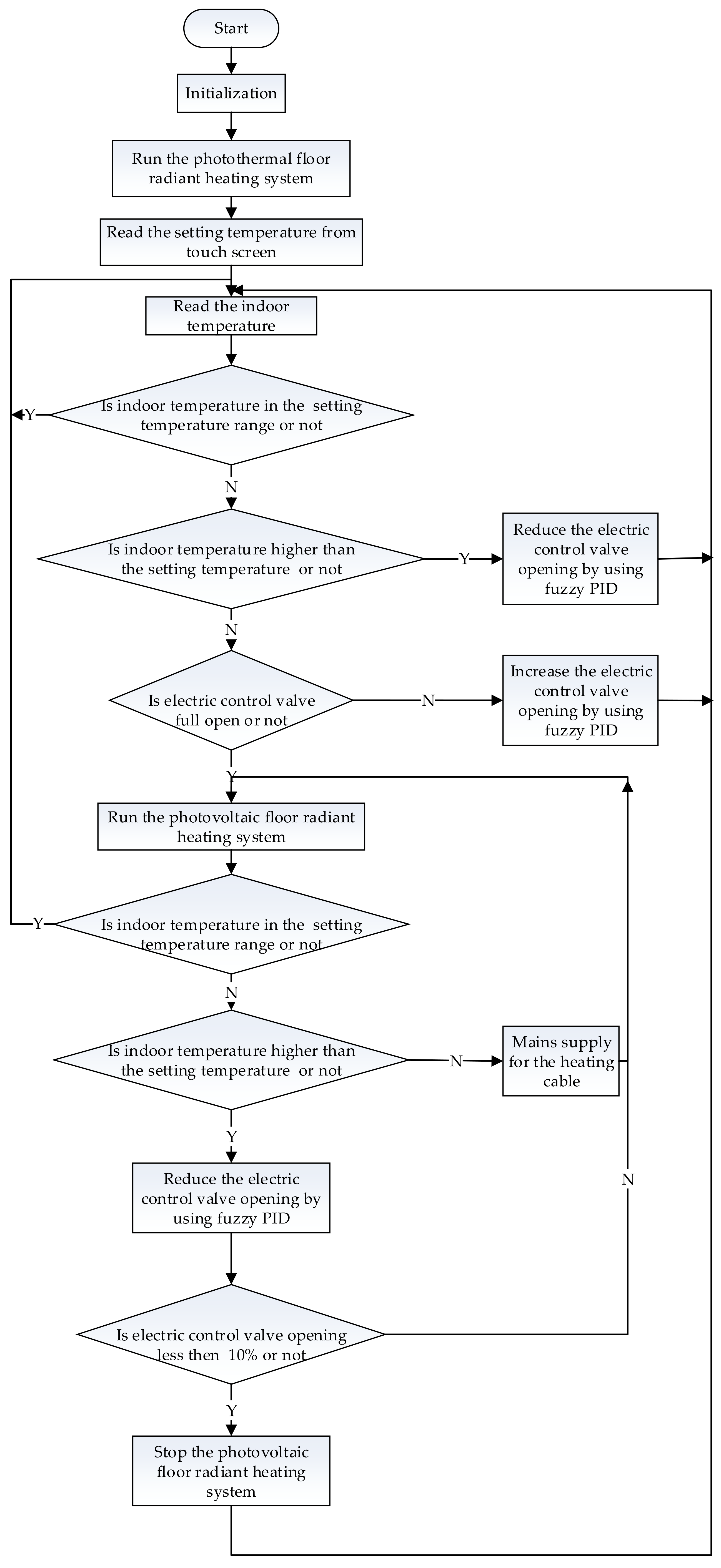
The control strategy of this research is preferentially used in the photothermal floor radiant heating system. It controls the indoor temperature using the fuzzy PID algorithm to adjust the opening of the electric control valve. If the indoor temperature still cannot be satisfied by the requirements when the electric control valve is completely open, it will mean that the supply of the floor radiant heating system is insufficient and the photovoltaic floor radiant heating system should be started. If the indoor temperature still cannot meet the requirements after using the photovoltaic floor radiant heating system, it must use the mains supply for the AC heating cables. If the indoor temperature is too hot after using the photovoltaic floor radiant heating system, the fuzzy PID algorithm can be used to reduce the opening of the electric control valve to adjust the indoor temperature of the photothermal floor radiant heating system. This adjustment method can reduce the start/stop frequency of the photovoltaic floor radiant heating system to improve the useful life of the system. When the electric control valve opening is less than 10% (almost closed), the photovoltaic floor radiant heating system should be stopped. The temperature set point is an allowable range. The indoor temperature should be adjusted when it falls outside this range. Therefore, the control system can reduce movement frequency and adjustments to improve the stability of the proposed floor radiant heating system. In addition, the temperature change and adjustment processes in the flow process chart of the main program (such as running the photothermal floor radiant heating system, regulating the electric control valve opening via the fuzzy PID, running the photovoltaic floor radiant heating system, using the mains supply for heating the cables and stopping the photovoltaic floor radiant heating system) should be set with a delay. The running process begins the next step when the indoor temperature is stable. The flow process chart of the main program is shown in Figure 5.
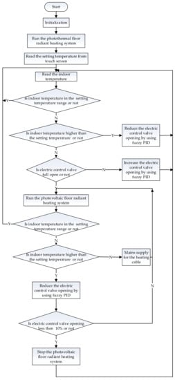
Figure 5.
Flow process chart of the main program.
4. Experimental System Design
The purpose of this experimental system is to obtain the indoor temperature distribution characteristics of the floor radiant heating system proposed in this research. On the basis of the experiment, the thermal comfort level of the heating system could be further evaluated. The heating for the proposed floor radiant heating system is provided completely by the solar energy system. The heat energy for the photothermal floor radiant heating system is provided by the solar thermal utilization system, and the electrical energy from the photovoltaic floor radiant heating system is provided by the photovoltaic power generation system.
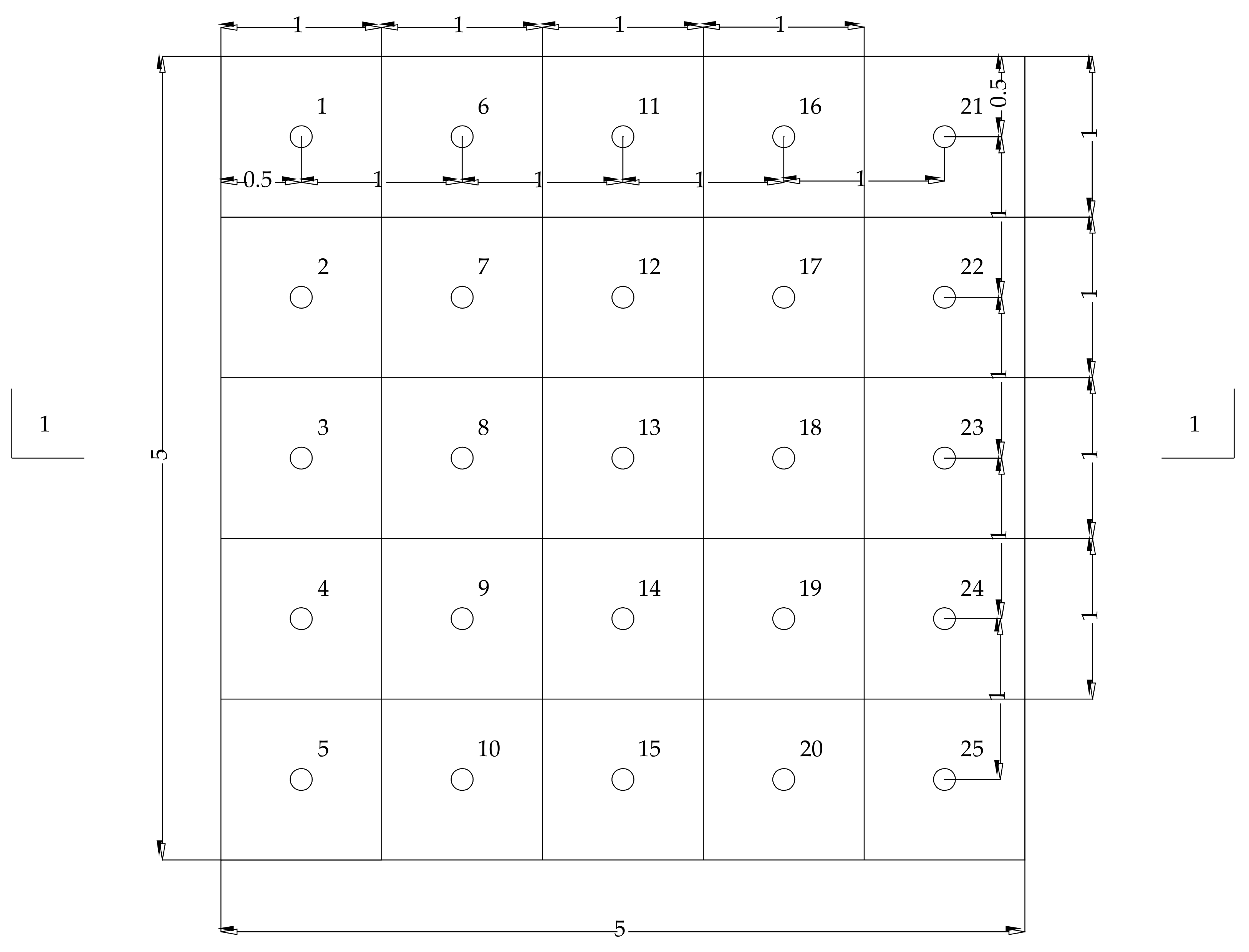
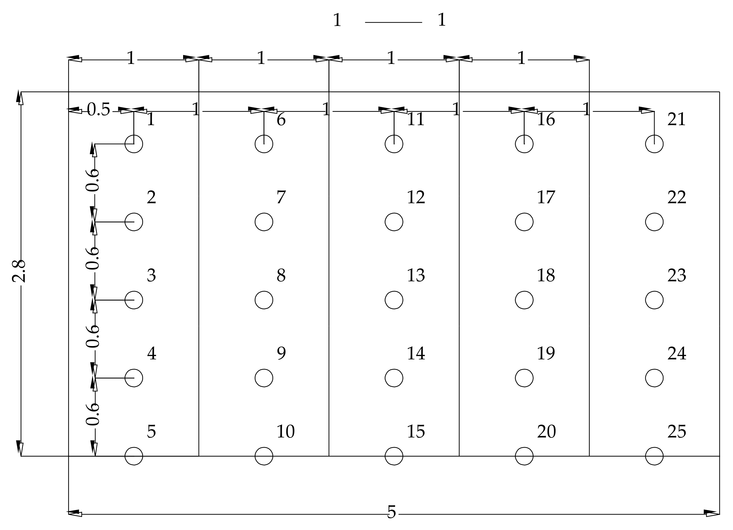
The heating test room is shown in Figure 6 and Figure 7. The length, width, and height is 5, 5 and 2.8 m, respectively. The units of all dimensions in Figure 6 and Figure 7 are meters. The horizontal direction of the indoor area can be divided into 25 equal areas. The center of each area is a test point, and the specific positions are shown in Figure 6. Other test points are arranged in the room vertically, shown in Figure 7. The indoor space can be divided into five layers with heights from the ground of 0, 0.6, 1.2, 1.8, 2.4 m. A total of 25 test points are placed on each floor, with 125 test points in total. All the temperature measurement points are located in the effective sensing area of human body induction for indoor temperature and comfort.

Figure 6.
The horizontal distribution diagram of the experimental test points.
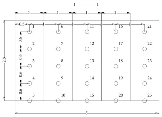
Figure 7.
The vertical distribution diagram of the experimental test points.
4.1. Indoor Temperature Distribution Experiment
According to the flow process in Figure 5, the proposed floor radiant heating system is tested in this research. When the system and indoor temperature are stable, the experimental data collection will start. The total heating is 60 w/m2 in this experiment.
In total, 125 test points for obtaining dry-bulb temperatures are measured by using thermocouples. All the thermocouples are connected to a data logger that collects the data every 60 s. The major instrument is the thermocouple, which measures the temperature within a range from −50 to 100 °C, and the accuracy is ± (0.05%rdg + 0.5 °C). The thermocouples were calibrated and aligned before the test.
The experimental procedure is as follows:
- Measure the geometric dimensions of the room and obtain the geometric parameters of the room.
- Let the thermocouples connect to the data acquisition device and begin the interactive debug.
- Start the experimental test and wait for a period of time until the room reaches a steady state. Then, read the thermocouple data once every 60 s and take the average value over a period of 1800 s as the final experiment data.
- Record all the data.
4.2. Indoor Temperature Change Rate Experiment
The experimental tests of the indoor temperature change rate were carried out on three different heating systems, i.e., the photovoltaic floor radiant heating system, the photothermal floor radiant heating system and the proposed floor radiant heating system. The AC heating cables are laid in the floor of the photovoltaic floor radiant heating system. The water pipes are laid in the floor of the photothermal floor radiant heating system. The proposed floor radiant heating system is arranged as shown in Figure 1, and its running program meets the flow process as shown in Figure 5.
The three different heating systems have the same initial value of indoor temperature, which is 2 °C, and the set value of indoor temperature is 20 °C. The three heating systems are used to heat the room, and the running time is 36,000 s. The instrument details are shown in Section 4.1. The 125 indoor test points are shown in Figure 6 and Figure 7.
The experimental procedure is as follows:
Procedures a, b, c are the same as the first three steps of Section 4.1.
- d.
- Choose the photovoltaic floor radiant heating system and begin the experimental test from the initial state (2 °C). After 36,000 s, stop the photovoltaic floor radiant heating system until the indoor temperature returns to its initial state. Collect data from the 125 thermocouples every 60 s during the whole test process and take the average temperature as the final value of the indoor temperature. The sampling period of this experiment is 60 s.
- e.
- Record all the data.
- f.
- Select the photothermal floor radiant heating system and the proposed floor radiant heating system to repeat the above steps.
5. Results and Discussion
5.1. Indoor Temperature Distribution
It can be shown that there is a large temperature difference between the maximum and the minimum of the indoor floor surface temperature (Table 1). There are some reasons:

Table 1.
Results of 125 temperature measurement points.
- a.
- The test point of the minimum is set near the wall and close to the floor, which means that the position is quite far away from the heat source;
- b.
- The test point of the maximum is in the middle of the heating system, which has less heat loss and a smaller heat change, so the measured temperature is relatively high.
Due to these reasons, the temperature at the position that is near the heat source is higher than in other locations. These results indicate that the difference in the indoor floor surface temperature is larger and the thermal comfort is poor. The inhomogeneity of the indoor floor surface temperature distribution is larger than in other locations, and the standard deviation of the indoor floor surface temperature can reach 1.87 °C.
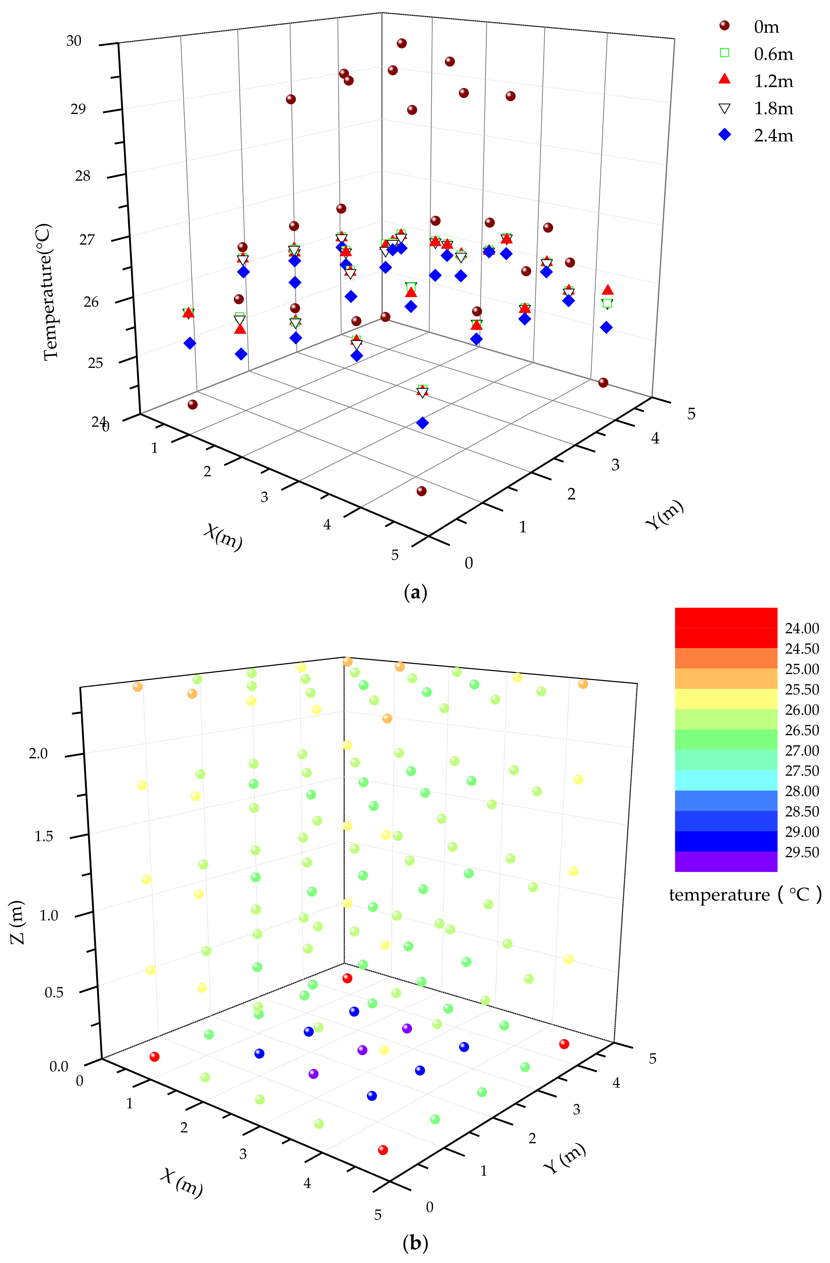
At the positions of 0.6 m, 1.2 m, 1.8 m and 2.4 m, the temperature homogeneity of the test points is better than that of the indoor floor surface, and the average temperature is 26 °C (ranged from 25 °C to 27 °C), which is also shown in Table 1. The maximum temperature deviation is almost the same at positions of 0.6 m, 1.2 m and 1.8 m, and the standard deviation is 0.36 °C, which indicates that the temperature homogeneity of positions 0.6 m to 1.8 m is the best among the different positions. From Table 1, it can be demonstrated that the thermal comfort is the best between positions 0.6 m to 1.8 m, which are the active regions of most people.
The temperature distributions of the different positions are revealed in Figure 8. Because the indoor floor surface is near the heat source, the average of the indoor floor surface temperature is obviously higher than in other locations. As the height of the test points increases, the temperature decreases and the temperature gradient exhibits a small change. With respect to the proposed floor radiant heating system, the temperature homogeneity of the whole room is preferable, as is the thermal comfort.
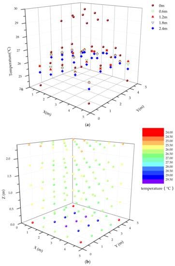
Figure 8.
Temperature distribution. (a) Temperature distribution of different layers; (b) Temperature distribution across all positions.
5.2. Indoor Temperature Change Rate
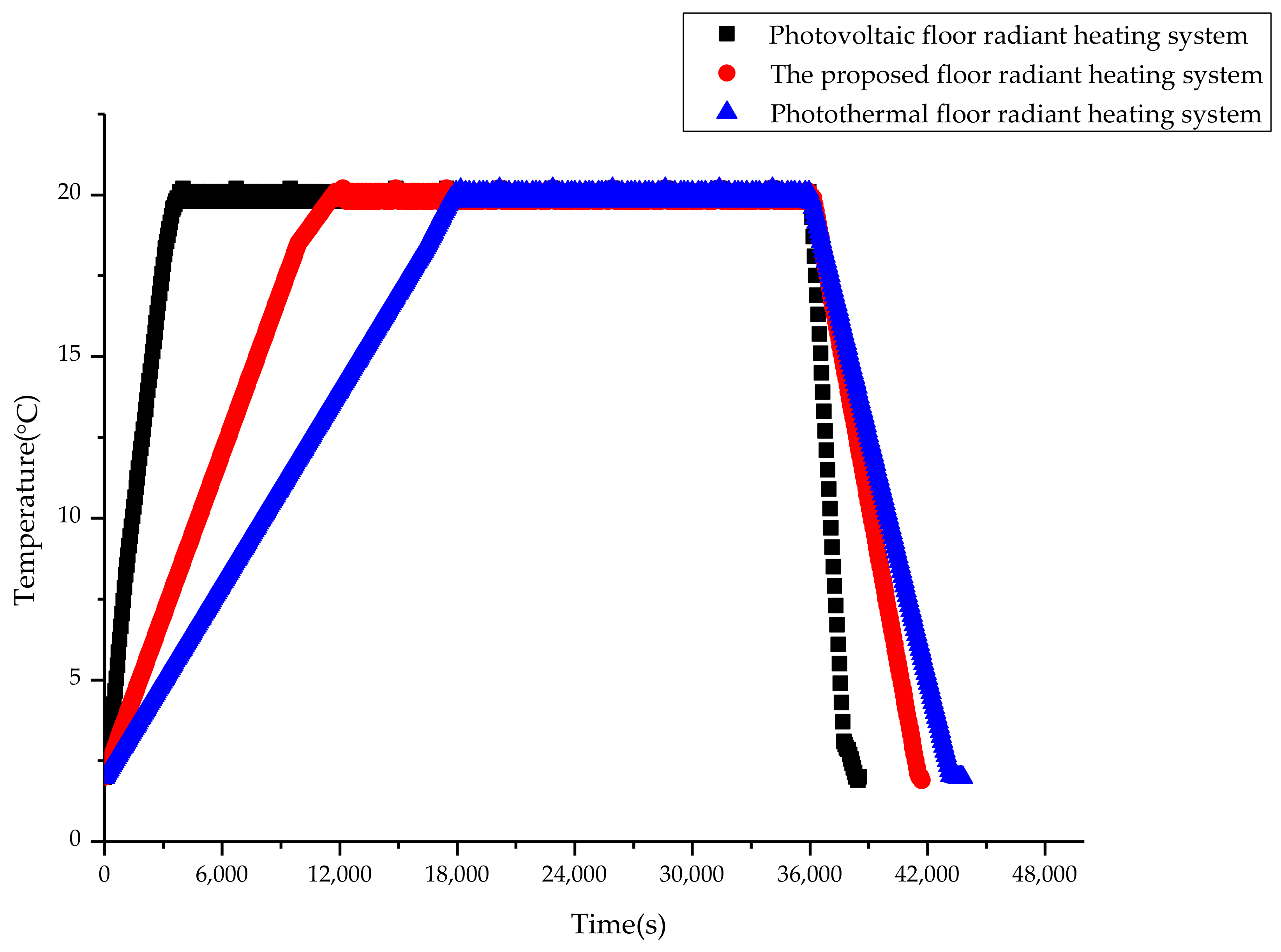
Figure 9 illustrates the indoor temperature change of the three different heating systems.

Figure 9.
Indoor temperature changes of the three different heating systems.
The heating and cooling speed of the photovoltaic floor radiant heating system is the fastest among the three different heating systems. The indoor temperature reaches the set temperature (20 °C) in more than 3600 s, and the indoor temperature will drop to its initial value in less than 1800 s. This result could be due to the thermal inertia of the heating cables of the photovoltaic floor radiant heating system. Under the same test time, the photovoltaic floor radiant heating system meets the setting temperature requirements in the longest time, which also reflects the largest energy consumption of electricity by the photovoltaic floor radiant, heating system.
The heating and cooling speed of the photothermal floor radiant heating system is the slowest. The indoor temperature reaches the set temperature in more than 18,000 s and returns to its initial value in more than 7200 s. This is the advantage of the photothermal floor radiant heating system, which is attributed to the heat inertia of water to maintain the indoor temperature balance when the system is not heating. It also can be shown that the time to meet the set temperature requirements of the photothermal floor radiant heating system is the shortest under the same test time (Figure 9). This requires that the photothermal floor radiant heating system should be operated in advance and run for a period of time to meet the indoor thermal comfort level, which would lead to a considerable consumption of energy.
The heating and cooling speed of the proposed floor radiant heating system is between the above two systems. The time to meet the set temperature is longer than that of the photothermal floor radiant heating system under the same test time, and the energy consumption is the lowest among the three different heating systems because the photovoltaic floor radiant heating system needs more electrical energy, and the photothermal floor radiant heating system requires more energy to meet the indoor temperature setting. The defects of the above two systems have been solved by the proposed floor radiant heating system, which has higher requirements for the control system.
6. Actual System Energy Savings Calculation and Analysis
6.1. Calculation
The total heat of the proposed floor radiant heating system can be calculated based on this section. The total heat of the proposed floor radiant heating system can be provided by solar energy except in extreme cases. The heat supplied by solar energy is the energy saving relative to the traditional floor radiant heating system. The heat calculation of the proposed floor radiant heating system is shown below:
- a.
- For the normal operation of the proposed floor radiant heating system, the following conditions need to be satisfied for calculation purposes; these conditions exist in the actual system:
- (a)
- The heat transfer process is stable during the normal operation of the proposed floor radiant heating system. All heat transfer analyses occur under steady state conditions.
- (b)
- The room temperature is constant during the normal operation of the proposed floor radiant heating system.
- (c)
- The insulation material, with a certain thickness, is laid in the floor. The heat transferred to the underside through the insulation material and the heat lost from the floor are negligible.
- (d)
- The thermal contact resistances are negligible. The material quality of all layers is uniform, and the physical properties are the same and constant.
- (e)
- Hot water flow is stable in the photothermal floor radiant heating system; the heating cable current is stable in the photovoltaic floor radiant heating system.
- (f)
- The surface temperature of hot water pipes and heating cables is uniform.
- (g)
- The normal operation of the proposed floor radiant heating system does not involve starting, stopping or other non-normal process.
- b.
- Calculation of heat calculation provided by floor radiant heating system
According to heat transfer theory, instantaneous heat provided by the floor radiant heating system is as follows (Equation (3)):
where:
is the instantaneous heat provided by the floor radiant heating system, W/m2; is the instantaneous radiation heat provided by the floor radiant heating system, W/m2; is the instantaneous convection heat provided by the floor radiant heating system, W/m2.
- c.
- The heat provided by the photothermal floor radiant heating system of the proposed floor radiant heating system is calculated.
The heat transfer process of the photothermal floor radiant heating system of the proposed floor radiant heating system involves the following: hot water in the pipes transmits heat to the pipe wall first; then, the floor is heated and the floor transfers heat to the walls and indoor air through convection and radiation. The calculation of the heat transfer process, in the floor, follows classical heat transfer theory, which is not repeated here.
The instantaneous heat provided by the photothermal floor radiant heating system of the proposed floor radiant heating system is as follows (Equations (4)–(7)):
where:
is the instantaneous heat provided by the photothermal floor radiant heating system of the proposed floor radiant heating system, W/m2; is the instantaneous radiation heat provided by the photothermal floor radiant heating system of the proposed floor radiant heating system, W/m2; is the instantaneous convection heat provided by photothermal floor radiant heating system of the proposed floor radiant heating system, W/m2; is the floor surface temperature, which is measured by an infrared thermometer to calculate the heat from the photothermal floor radiant heating system, °C; is the indoor temperature, which is measured by the indoor temperature and humidity sensor, °C; is the average radiant temperature of non-heated surfaces, °C, ( is the surface temperature of each part (°C); is the area of the corresponding enclosure structure (m2)).
The total heat provided by the photothermal floor radiant heating system of the proposed floor radiant heating system is as follows (Equation (8)):
where:
is the total operation time of the photothermal floor radiant heating system in one year, s; is the total heat provided by the photothermal floor radiant heating system of the proposed floor radiant heating system, W/m2. The total operation time is defined as the sum of the operating time of the photothermal system and its energy storage system.
- d.
- The heat provided by the photovoltaic floor radiant heating system of the proposed floor radiant heating system is calculated.
For the photovoltaic floor radiant heating system of the proposed floor radiant heating system, the heat transfer process includes the following: the heating cables heat the floor and then the heat from the floor is transferred to the walls and indoor air by convection and radiation. The heat transfer process of the photovoltaic floor radiant heating system is different from that of the photothermal floor radiant heating system. The equations are as follows (Equation (9)):
where:
is the heat per unit length of the heating cable provided by the photovoltaic floor radiant heating system, W/m; is the heating cable current of the photovoltaic floor radiant heating system, A; is the correctional resistance of heating cables of the photovoltaic floor radiant heating system, Ω/m (Equation (10)).
where:
is the resistance of the heating cables, Ω/m; is the thermal coefficient of material resistance, °C−1; is the coefficient of thermal expansion, °C−1; is the surface temperature of heating cable, °C (Equation (11)).
where:
is the instantaneous heat provided by the photovoltaic floor radiant heating system of the proposed floor radiant heating system, W/m2; is the instantaneous radiation heat provided by the photovoltaic floor radiant heating system of the proposed floor radiant heating system, W/m2; is the instantaneous convection heat provided by the photovoltaic floor radiant heating system of the proposed floor radiant heating system, W/m2; is the floor surface temperature, which is measured by an infrared thermometer to calculate the heat from the photovoltaic floor radiant heating system, °C.
The total heat provided by the photovoltaic floor radiant heating system of the proposed floor radiant heating system is calculated as follows (Equation (12)):
where:
is the total operation time of the photovoltaic floor radiant heating system in one year, s; is the total heat provided by the photovoltaic floor radiant heating system of the proposed floor radiant heating system, W/m2. The total operation time is defined as the sum of the operating time of the photovoltaic system and its energy storage system.
- e.
- Calculation of the total heat provided by the proposed floor radiant heating system
The total heat provided by the proposed floor radiant heating system involves the total heat provided by the photothermal floor radiant heating system, the total heat provided by the photovoltaic floor radiant heating system and the supplementary heat provided by the auxiliary heat source in extreme cases. The total heat is (Equation (13)):
where:
is the total heat provided by the proposed floor radiant heating system, W/m2; is the supplementary heat provided by the auxiliary heat source in extreme cases, W/m2.
- f.
- Revised calculation of the total heat provided by the proposed floor radiant heating system
The proposed floor radiant heating system involves two different heating systems that have different loads, and the auxiliary heating system is also considered in extreme cases. Therefore, it is necessary to use the load factors to revise the total heat calculation of the proposed floor radiant heating system.
The total load provided by the proposed floor radiant heating system includes the load provided by the photothermal floor radiant heating system, the load provided by the photovoltaic floor radiant heating system and auxiliary heat load in extreme cases.
The load factors are , , . The revised calculation of total heat is (Equations (14) and (15)):
where:
is the proportion of the load of the photothermal floor radiant heating system relative to the total load, %; is the proportion of the load of the photovoltaic floor radiant heating system relative to the total load, %; is the proportion of the load of auxiliary heating system relative to the total load in extreme cases, %; is the total heat provided by the proposed floor radiant heating system for correct calculation, W/m2.
- g.
- Calculation of total heat provided by the proposed floor radiant heating system in extreme casesThere are three extreme cases:
- (a)
- The photovoltaic floor radiant heating system cannot provide heat, and the photothermal floor radiant heating system can provide only a little heat. Most heat is provided by the auxiliary heat source. The total heat (Equation (16)):where:is the total heat provided by the proposed floor radiant heating system in the first extreme case, W/m2.
- (b)
- Neither the photovoltaic floor radiant heating system nor the photothermal floor radiant heating system can provide heat. The total heat is provided by the auxiliary heat source. The photothermal floor radiant heating system must be turned off immediately to avoid indoor heat loss when the photothermal floor radiant heating system cannot provide heat. The total heat (Equations (17)):where:is the total heat provided by the proposed floor radiant heating system in the second extreme case, W/m2.
- (c)
- The photothermal floor radiant heating system cannot provide heat and the photovoltaic floor radiant heating system can provide only a little heat. The major heat is provided by the auxiliary heat source. The total heat (Equations (18)):where:is the total heat provided by the proposed floor radiant heating system in the third extreme case, W/m2.
The photothermal floor radiant heating system must be turned off immediately to prevent indoor heat loss when the photothermal floor radiant heating system cannot provide heat.
6.2. Operation and Analysis
The calculation procedure of the heat energy provided by the proposed floor radiant heating system refers to Equations (3)–(18). To evaluate the energy saving potential of the proposed floor radiant heating system accurately, a modified equation for the proposed floor radiant heating system is shown by Equation (14). To calculate the available heat energy of the proposed floor radiant heating system under extreme conditions, the revised calculation method is also given by Equations (16)–(18). All the calculation methods have been used for the actual heating system, and the analysis will be shown in the subsequent paragraphs.
A series of tests and data collection for one year’s operation of a civil building have been implemented, and the energy saving of the proposed floor radiant heating system has been calculated and analyzed in this paper.
The heating area of the civil building is approximately 1500 m2. The heating period for this region is from 15 November to 15 March of the following year.
As the proposed floor radiant heating system is a solar floor radiant heating system, the heating time of the system is determined according to the indoor temperature setting (20 °C). The heating system starts to run when the indoor temperature is below the set temperature. The total running time of the proposed floor radiant heating system is 10,551,600 s based on one year’s test and data collection. The operation time of the proposed floor radiant heating system is 241,200 s when the indoor temperature is below the set temperature in the transition season, and its operation time is 486,000 s under extreme conditions. The ratio of the transition season and extreme conditions to the running time is 2.3% and 4.6%, respectively. Therefore, it can be seen that the proposed floor radiant heating system has heating flexibility, which means that it can meet the heating requirements throughout the year.
Based on the calculation from Equations (3)–(18), the average energy per unit area provided by the proposed floor radiant heating system is 43.26 W/m2, excluding extreme conditions. This confirms the energy saving potential relative to the traditional floor radiant heating system. Compared with the conventional radiant heating system powered by fossil fuels, standard coal consumption and CO2 emissions can be reduced by 17.3 kg/m2 and 43.1 kg/m2, respectively, in this proposed floor radiant heating system on the basis of the energy saving potential. From an economic point of view, the heating price of this civil building can be reduced by more than 6 yuan/m2.
The proposed calculation method involves the total heat calculation method, the revised calculation method and total heat calculation method under extreme conditions, which can be provided by the proposed floor radiant heating system. The calculation and analysis of the solar floor radiant heating system can be achieved by this calculation method under different conditions. The proposed floor radiant heating system has heating flexibility and can meet the heating requirements for the transition season and achieve energy savings and emission reductions. In the case of no heating, the excess energy of the proposed floor radiant heating system can be stored or used for basic household energy.
7. Conclusions
The proposed system combines two different heat sources for floor radiant heating and makes full use of solar energy to provide energy. The characteristics of the rapid response with AC heating cables and the slow cooling process with hot water are used to improve the stability of heating and the efficiency of the system. The system can run stably under off-grid conditions with a self-powered design that only requires mains power supply in extreme cases. In addition, the system can also use night valley electricity to charge the battery to improve energy efficiency and to save energy. The system can replace fossil fuels used in a traditional central heating system, and it also has strong heating flexibility. This system has amazing potential, especially in areas without central heating. The fuzzy PID control system has been designed to ensure precise control for comfortable indoor conditions.
The proposed system has been researched and tested through experiments. The experimental results show that the difference in the indoor floor surface temperature is large, the thermal comfort is poor and the inhomogeneity of temperature distribution is larger compared with other surfaces. The standard deviation of the indoor floor surface temperature can reach 1.87 °C. The maximum value of the temperature is almost the same, and the minimum standard deviation is approximately 0.36 °C at 0.6 m, 1.2 m, and 1.8 m. The result of the minimum standard deviation shows that the best homogeneity of temperature and thermal comfort is from 0.6 m to 1.8 m. Under the same testing time, the proposed floor radiant heating system, which does not need to be turned on in advance and operated for a long time, has a higher heating rate than the photothermal floor radiant heating system. Therefore, the proposed floor radiant heating system does not have higher energy consumption, but it has higher requirements for the control system.
In this paper, the proposed calculation method involves the total heat calculation method, the revised calculation method and total heat calculation method under the extreme conditions, which can be provided by the proposed floor radiant heating system. The calculation and analysis of the floor radiant heating system driven by solar energy can be achieved by this calculation method under different conditions. At the same time, the calculation methods are applied to the actual heating system, of which the energy savings can reach 43.26 W/m2.
Therefore, the proposed floor radiant heating system is an efficient and environmental system that reduces the emission of pollutants based on energy saving. It can be widely applied to areas that need heating systems.
Acknowledgments
This research was supported by the Tianjin Education Science “The 13th Five-year” Program Project “Research on the cultivation of systematic talents of the energy specialty” (Project No. VEYP5040) and Teaching reform and construction project of Tianjin Sino-German University of Applied Sciences (Project No. ZDJY2017-06).
Author Contributions
All the authors significantly contributed to the editing and improvement of the manuscript. Lian Zhang conceived and designed the floor radiant heating system based on energy substitution technology. Baowen Cao performed the experiments and designed the control system. All the authors analyzed the data and wrote the paper.
Conflicts of Interest
The authors declare no conflict of interest.
References
- Bojić, M.; Cvetković, D.; Marjanović, V.; Blagojević, M.; Djordjević, Z. Performances of low temperature radiant heating systems. Energy Build. 2013, 61, 233–238. [Google Scholar] [CrossRef]
- Izquierdo, M.; Pablo de Agustín, E.M. A micro photovoltaic-heat pump system for house heating by radiant floor: Some experimental results. Energy Procedia 2014, 48, 865–875. [Google Scholar] [CrossRef]
- Izquierdo, M.; Agustín-Camacho, P.D. Solar heating by radiant floor: Experimental results and emission reduction obtained with a micro photovoltaic-heat pump system. Appl. Energy 2015, 147, 297–307. [Google Scholar] [CrossRef]
- Jeong, Y.D.; Yu, M.G.; Nam, Y. Feasibility Study of a Heating, Cooling and Domestic Hot Water System Combining a Photovoltaic-Thermal System and a Ground Source Heat Pump. Energies 2017, 10, 1243. [Google Scholar] [CrossRef]
- Sarbu, I.; Sebarchievici, C. Performance Evaluation of Radiator and Radiant Floor Heating Systems for an Office Room Connected to a Ground-Coupled Heat Pump. Energies 2016, 9, 228. [Google Scholar] [CrossRef]
- Sebarchievici, C.; Sarbu, I. Performance of an experimental ground-coupled heat pump system for heating, cooling and domestic hot-water operation. Renew. Energy 2015, 76, 148–159. [Google Scholar] [CrossRef]
- Dupeyrat, P.; Ménézo, C.; Fortuin, S. Study of the thermal and electrical performances of PVT solar hot water system. Energy Build. 2014, 68, 751–755. [Google Scholar] [CrossRef]
- Herrando, M.; Markides, C.N.; Hellgardt, K. A UK-based assessment of hybrid PV and solar-thermal systems for domestic heating and power: System performance. Appl. Energy 2014, 122, 288–309. [Google Scholar] [CrossRef]
- Zhang, L.; Chen, Z.J. Design and Research of the Movable Hybrid Photovoltaic-Thermal (PVT) System. Energies 2017, 10, 507. [Google Scholar] [CrossRef]
- Zhang, P.F.; Dang, K.F.; Zhang, Y.J. Control and Simulation of Temperature for Injection Molding Machines Based on Self-Adaptive Fuzzy PID Control Method. China Plast. 2013, 27, 85–89. [Google Scholar]
- Montoya-Marquez, O.; Flores-Prieto, J.J. The Effect of the Angle of Inclination on the Efficiency in a Medium-Temperature Flat Plate Solar Collector. Energies 2017, 10, 71. [Google Scholar] [CrossRef]
- Valíček, J.; Palková, Z.; Harničárová, M.; Kušnerová, M.; Lukáč, O. Thermal and Performance Analysis of a Gasification Boiler and Its Energy Efficiency Optimization. Energies 2017, 10, 1066. [Google Scholar] [CrossRef]
- Moradi, H.; Setayesh, H.; Alasty, A. PID-Fuzzy control of air handling units in the presence of uncertainty. Int. J. Therm. Sci. 2016, 109, 123–135. [Google Scholar] [CrossRef]
- Chao, C.T.; Sutarna, N.; Chiou, J.S.; Wang, C.J. Equivalence between Fuzzy PID Controllers and Conventional PID Controllers. Appl. Sci. 2017, 7, 513. [Google Scholar] [CrossRef]
- Xia, D.Z.; Kong, L.; Hu, Y.W.; Ni, P.Z. Silicon micro gyroscope temperature prediction and control system based on BP neural network and Fuzzy-PID control method. Meas. Sci. Technol. 2015, 26. [Google Scholar] [CrossRef]
- Gu, Q.; Zheng, F.L.; Liu, B.B.; Yang, W.Y. Application of a New Smith Fuzzy PID in Electric Boiler Temperature Control System. Appl. Mech. Mater. 2015, 727–728, 633–636. [Google Scholar] [CrossRef]

© 2018 by the authors. Licensee MDPI, Basel, Switzerland. This article is an open access article distributed under the terms and conditions of the Creative Commons Attribution (CC BY) license (http://creativecommons.org/licenses/by/4.0/).