Abstract
This paper is concerned with the study of low-cost, low-power thermoacoustic electricity generators. Based on target electrical output power values of 50 and 100 W, three standing wave prototypes (of both one-stage and two-stage prototypes) integrating a commercial loudspeaker with different coupling arrangements are conceived. Each stage consists of a square-pore stack sandwiched between hot and ambient heat exchangers. The working gas is air at atmospheric pressure. The prototypes’ efficiency in converting heat to electrical power is simulated by the specialized Design Environment for Low-Amplitude ThermoAcoustic Engines (DeltaEC) design tool based on the linear theory of thermoacoustics. At a given operation frequency, the optimal impedance matching between the loudspeaker and the engine is realized by adjusting both the engine parameters (stack location, stack length, heat exchangers length, loudspeaker location) and loudspeaker parameters (load resistance and box volume). Computations reveal that the one-stage engine and two-stage engine with loudspeakers coupled in side-branch mode are able to meet the target output power values with comparable thermal-to-electric efficiency (4.6%). The two-stage engine with the loudspeaker coupled in push–pull mode is unable to reach the desired power output and is characterized by low conversion efficiencies (2%) due to the poor loudspeaker–engine acoustic impedance matching.
1. Introduction
Thermoacoustic (TA) engines are energy conversion devices (prime movers, refrigerators and heat pumps) whose operation relies on the interaction between heat and sound near solid surfaces, a phenomenon identified as the “thermoacoustic effect” [1]. Since in these devices the phasing of the transformations which build up the underlying thermodynamic cycle is naturally accomplished by an acoustic wave (rather than by pistons, valves and displacers), there are a number of technological benefits. First of all, there is the complete absence of moving mechanical parts, which leads to engineering simplicity, reliability, longevity, and low maintenance costs. Secondly, they are intrinsically low cost, being constituted basically by a small number of standard components made of inexpensive and common materials, namely pressure vessels (acoustic networks/resonators), solid porous materials (stack/regenerators), heat exchangers (generally of the finned-tube or shell-and-tube type), and electroacoustic transducers. Furthermore, they use environment friendly working fluids, can be employed in a large variety of applications (those involving heating, cooling or power generation), and can be driven by different power sources (gas/biomass combustion, solar energy, etc.) allowing, in particular, the exploitation of waste heat and renewable energy sources, since they are potentially configurable to operate with low temperature differentials [2]. These characteristics make TA technology a discipline of relevant interest for the energy industry, giving it a primary position among emerging renewable energy technologies.
A great body of research in TA technology is being developed, specifically with respect to TA electricity generators (TAEGs). A TAEG is essentially a TA engine coupled to an electroacoustic transducer (linear alternator, loudspeaker, etc.) to convert a fraction of the useful acoustic power (generated from heat) into electrical output energy. Flexure-bearing supported linear alternators (LAs) characterized by low friction losses are generally applied for acoustic-to-electric transduction in TAEGs since they are capable of achieving transduction efficiencies of up to 90%. Relevant examples of this new class of electricity generators integrating LAs in TA engines are, among others, the demonstrators developed by Backhaus et al. [3], Wu et al. [4], and Wang et al. [5], all working at thermal-to-electric efficiencies (ηhe) near 18%. Standard electrodynamic loudspeakers (LSs) operated in reverse mode can be also used in lieu of LAs, but in low-power applications (a few hundred watts). This is due to the fact that an LS, generally designed for high-fidelity applications, is characterized by a weak and fragile cone, a short stroke, low power handling, and a low acoustic-to-electric efficiency (ηae). In any case, when a particular application requires low power levels, low cost for generated kWe, and not very high transduction efficiencies (~50%) the use of LSs could be justified. Relevant examples of this new class of electricity generators integrating LSs in TA engines are the prototypes developed by Yu et al. [6] and Kang et al. [7] working at thermal-to-electric efficiencies (ηhe) below 5%.
This work is specifically concerned with the study/development of low-cost TAEGs of the standing wave-type using standard LSs as LAs. Throughout the work, a theoretical analysis of LAs is firstly outlined. Three different configurations are then considered for coupling the LA to the TA engine which, in order to respect cost and technological simplicity requirements, is conceived to work with air at atmospheric pressure. Finally, the prototypes’ behavior is simulated by standard codes based on the linear theory of thermoacoustics and their performance is compared.
2. Theoretical Modeling of Linear Alternators
The physical behavior of an LA is quantitatively modeled in the frequency domain by the well-known canonical equations for an antireciprocal transducer. These equations are conveniently written in complex notation, which allows us to express any variable a(t) oscillating harmonically at angular frequency ω about its mean value a0 as
where t is the time, of the imaginary unit j, Re{ } signifies the real part, and the complex amplitude A accounts for both magnitude and phase of the oscillation. Neglecting hysteresis losses and considering that the electric terminals are closed on a load electric resistance RL, the canonical equations assume the form of the following two linear equations [8]
where p1 and p2 are the complex amplitudes of the acoustic pressures acting on the front and back sides, respectively, of the diaphragm of area Ad, I is the complex amplitude of the current flowing in the voice coil, U is the complex amplitude of the volumetric velocity due to the diaphragm motion, Bl is the “force factor” (the product of the magnetic field, B, times the length of the voice coil wire, l), and Ze (the electrical impedance with blocked diaphragm) and Zm (the mechanical impedance with open electric circuit) are
with Re and Le being the electrical resistance and inductance of the voice coil, Rm the mechanical resistance of the system, m the mass of the diaphragm and voice coil, and Km the mechanical stiffness of the elastic suspensions.
By solving Equations (2) and (3) the following expression of the acoustic impedance of the LA is found
The acoustic power absorbed by the alternator can be written in the following equivalent forms
where ϕpU is the phase angle between the pressure difference (p1 − p2), and U and the tilde symbol indicate complex conjugation. Substitution of Equation (6) into Equation (7) provides
This equation shows that a fraction of the absorbed acoustic power is dissipated by the mechanical resistance Rm, another fraction is consumed in the coil electrical resistance Re, and the remaining fraction is extracted by the load RL as electric power. The last term can be also written as
which shows that for delivering high electric power levels to the load, high oscillation velocities of the diaphragm are required. The acoustic-to-electric conversion efficiency is
From the above equations it results that the performance of an LA (expressed by the parameters ηae, Wa, and We) grows with increasing force factor (Bl) and with decreasing mechanical (Rm) and electrical (Re) resistances (in the ideal case Rm = Re = 0 the device would have an acoustic-to-electric efficiency of 100%). The performance also increases when the electrical reactance (Xe) is decreased. An additional condenser could be added to the coil circuit to use the alternator in favorable electrical resonant conditions (Xe = 0) at the selected operation frequency [9] (even if the inductance of the voice coil, ωLe, is generally negligible at the typical working frequencies of TA devices for standard woofers and sub-woofers). Finally, the amount of acoustic power absorbed by the alternator also grows with decreasing mechanical reactance Xm so the performance of the device is highest when it works in both mechanical and electrical resonant conditions (Xm = 0, Xe = 0) for which the alternator acoustical impedance becomes real (p1 − p2 in phase with U).
The optimal value of the load resistance maximizing the efficiency can be found from Equation (10) when written (neglecting the electrical reactance term) in the form
Equating to zero the derivative of this equation we find that the optimal load resistance is
Substituting this value in Equation (11) we find that the maximum achievable efficiency is
where β = (Bl)2/ReRm.
The value provided by Equation (12) differs from the value of the optimal load resistance that maximizes the electric output power. Using Equation (2), in fact, and indicating with |xmax| the maximum admissible diaphragm excursion (the corresponding maximum volume velocity being |Umax| = ωAd|xmax|), the maximum electrical output power is
which shows that for achieving high power levels, without working at increasingly values of the frequency, LAs characterized by high diaphragm excursions are required. Equation (14) maximizes for
that, when substituted in Equation (14), provides the maximum electric power obtainable at the operation frequency ω
To model the TA engine and its coupling to the LA, the Design Environment for Low-Amplitude ThermoAcoustic Engines (DeltaEC) computer code [10], developed at the Los Alamos National Laboratory, is used as design tool in the present work. The code integrates the linear theory of thermoacoustics, firstly formulated by Rott [11] and subsequently refined by Swift [12], which has demonstrated accurate precision for pressure amplitudes of up to 10% of the mean pressure. The code performs 1D numerical integration of the momentum, continuity, and energy equations through each segment of the acoustic network. These equations, considered in their linear approximation (low-amplitude) version, are:
as far as the momentum equation is concerned,
as far as the continuity equation is concerned, and
with
as far as the energy equation is concerned. In the above equations, ρ0 is the mean density, c is the sound velocity, γ is the ratio of isobaric to isochoric specific heats, T0 is the mean temperature, β is the thermal expansion coefficient, Pr is the Prandtl number, cP is the gas isobaric specific heat, K and Ks are the thermal conductivity of the gas and solid, respectively, H is the enthalpy flux along the direction of acoustic vibration x, fκ and fν are spatially averaged thermal and viscous functions depending on the geometry of the gas pores, A and As are the area of the transverse section open to gas flow and obstructed by the solid, respectively, εs is the ratio of specific heats per unit area of gas and solid, and q is the heat exchanged with external thermal reservoirs along the direction normal to x per unit length in the heat exchangers.
The solutions found for adjoining segments are then matched by imposing the continuity of pressure and volume flow rate at their junction. For further details the reader is referred to [12].
3. Acoustic Impedance Matching
The impedance matching between the alternator and the engine is a crucial task for designing high-performing devices. Optimal matching means that the presence of the alternator does not significantly alter the structure of the acoustic field (resonance frequency, pressure and velocity distributions, and their phase) which maximizes the engine performance in converting heat to acoustic power. Likewise, the structure of the acoustic field at the transducer location should make it absorb useful amounts of acoustic power, converting it to electrical power with high efficiency. In general, the optimal location of an LA in an acoustic field depends on the impedance of the transducer itself. This statement can be easily interpreted observing that the pressure drop (p1 − p2) across the LA and the local volume velocity (U) must always satisfy Equation (6). This requires high-impedance (or non-compliant) transducers, with high masses and suspension stiffness, to be preferably installed near high-impedance regions of the acoustic field and, conversely, low-impedance (or ultra-compliant) transducers, with low masses and suspension stiffness, to be preferably installed near low impedance regions of the acoustic field [1].
Standard LAs are generally low impedance-type transducers. For this kind of devices the above requirements on impedance matching can be effectively met by using enclosed housing or ducts of proper length (branches) which act as impedance-matching transformers. Since the acoustic impedance of an LA is a function of frequency, optimal matching requires preliminary a selection of its optimal working frequency ranges. This task can be accomplished by a simple design strategy using as inputs the target output power, We, and the maximum diaphragm excursion |xmax|. Observing that at the operation angular frequency ω the following two equations have to be verified
we can substitute the first into the second for |U| and then resolve the resulting equation with respect to ω. The result is
which allows us to determine, for a given load resistance RL, the operation frequency f compatible with the target output power and the maximum allowable stroke of the diaphragm. The f, and ηae values calculated through Equations (23) and (11) respectively, corresponding to the target output powers We (=50 and 100 W), are reported in Figure 1 as a function of RL. The volume flow rates generating the target power outputs can then be calculated by substituting these frequencies in Equation (21).
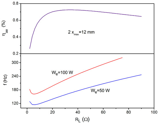
Figure 1.
The operation frequencies of the loudspeaker giving rise to an electrical output power values of 50 and 100 W, and the acoustic-to-electric conversion efficiency as a function of the load resistance.
For maximizing the amount of electric power generated by the LA it is desirable, according to Section 2, that its natural resonance frequency falls within the useful working frequency ranges above calculated. This brings the phase angle between p1 and p2 and U near zero, that enhances the acoustic power absorbed by the LA. For configurations involving LAs with enclosed housings, this condition could be met by adjusting the combined LA/housing impedance. The gas-spring effect caused by the back volume Vb of the housing is equivalent, in fact, to an increment of the suspension stiffness of the LA given by
which allows regulations of through variations of Vb.
The adjustment operated on Za (=Ra + jXa) to match the above condition has however a strong impact on the engine efficiency in converting heat to acoustic power (ηha) since Za acts as an acoustic load to the TA engine. Therefore, it contributes in determining the resonance frequency of the integral acousto-mechanical system and influences the structure of the acoustic field near the stack. So, an improper maximization of ηae and Wa could produce the detrimental effect of degrading the ηha performance. Proper impedance matching requires instead that the working conditions of the coupled system be optimal both for the TA engine in converting heat to acoustic power and the LA in converting acoustic power to electrical energy. Therefore, once a range of optimal working conditions for the LA alternator are selected, the resulting ω and Za values should be used as inputs in the optimization procedure of the TA engine for realizing impedance matching at the location where the LA is installed. In general, the above requirements cannot be met simultaneously and compromises should be made among them in the design phase when coupling the LA to the TA engine.
In the next section the procedure is applied in the case of standing wave TAEGs for three different coupling typologies of the LA.
4. Results and Discussion
The target electric output power of the engines is We = 50 W for one-stage engines and We = 100 W for two-stage engines. All the devices are standing wave-type engines (characterized by a 90° out-of-phase relationship between pressure and velocity oscillations) operated with air at atmospheric pressure. This choice meets the goal of the present study of developing low-cost TAEGs. The use of near atmospheric air, in fact, avoids the use of costly pressure vessels, eliminates the problems associated to the availability and cost of noble (or other exotic) gases, and reduces the engines’ size (and associated cost) due to the relatively low sound velocity.
The devices that are supposed to comprise the standard components are: (1) properly shaped ducts (the acoustic network/resonator) with the task of selecting the working frequency and the proper pressure–velocity time–phase relationship; (2) porous solid media (stacks) where the desired heat-sound energy conversion takes place; (3) heat exchangers/HXs (a hot heat exchanger/HHX and an ambient heat exchanger/AHX) sandwiching the stack and enabling heat communication with external heat sources and sinks; and (4) standard LAs converting acoustic power to electric power.
Specifically, the modeled stacks are commercially available ceramic substrates for automotive applications of the square pore-type with hydraulic radius equal to 0.2425 mm, porosity of 88.1%, and diameter of 13 cm. The HXs are of the fin-and-tube type with fin spacing, 2y0, equal to 1 mm and porosity 59% to avoid much too specific manufacturing requisites and relative high costs. The HHX temperature (TH) is assumed at a maximum to be equal to 500 °C to not exceed the tolerances of typical materials used for its construction. The AHX temperature (TA) is assumed to be maintained at TA = and to be made of copper. A commercially available LS (the B&C 6PS38 woofer manufactured by B&C speakers) is selected as an LA due to its relatively low mechanical resistance Rm, low electrical resistance Re, high force factor Bl, high ηmax parameter (=72.5%) and relatively small dimension (7-inch nominal diameter). The parameters of the LS are listed in Table 1.

Table 1.
Specifications of the loudspeaker. The parameter ηmax is calculated through Equation (13).
4.1. One Stage Engine
The simplest configuration of a TAEG is a straight half-wavelength (λ/2)-type resonator enclosing a stack/HXs assembly on one end and an LA on the other end (see Figure 2).
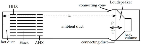
Figure 2.
Schematic of the one-stage standing-wave thermoacoustic electricity generator (TAEG) model. AHX: ambient heat exchanger; HHX: hot heat exchanger.
As is well known, in such kinds of resonators the acoustic impedance grows continuously from the central section to the end sections so the impedance matching requires in this case that the LA behave as an high-impedance transducer. Furthermore, since on the right side of the resonator the imaginary part of the impedance is negative (the pressure lags the velocity by a 90° phase angle) we have to select proper values of the back volume (and eventually of RL) to make the imaginary part of the input impedance of the coupled LA/housing negative.
Note that in this configuration the acoustic power irradiated in the back volume is negligible since it simply corresponds to the power dissipated on the housing surfaces by thermal hysteresis. Taking into account these circumstances, the TAEG has been numerically modeled by DeltaEC and for each working frequency f, the engine parameters (stack location, stack length, LA location) and the LA parameters (load resistance RL and back volume Vb) have been varied in order to find the optimal matching between the LA and the engine. In each simulation, the output electrical power and the peak-to-peak stroke of the diaphragm are fixed to 50 W and 12 mm, respectively, while the HHX and AHX lengths are modeled to match exactly the local peak-to-peak acoustic particle amplitude [1]. The geometrical dimensions of the engine deriving from the optimization procedure are given in Table 2. Results concerning the TAEG performance are shown in Figure 3 where the power values Wa, We, the efficiencies ηha, ηae, ηhe, and the impedance parameters |Za|, ϕpU are plotted as a function of f.
Table 2.
Geometrical parameters of the TAEG models and operation conditions.
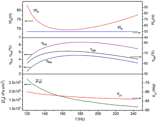
Figure 3.
The power values Wa, We, efficiencies ηha, ηae, ηhe, and the impedance parameters |Za|, ϕpU as a function of f.
From an inspection of the graphs it can be deduced that the heat-to-acoustic conversion efficiency ηha of the engine exhibits a maximum at f ≈ 180 Hz (with RL = 42.2 Ω). The behavior of ηha vs. f can be interpreted observing that decreasing the frequency starting from high values has the effect of reducing the absolute value of the phase angle ϕpU. This should have the positive effect of increasing the amount of acoustic power absorbed by the LA. This circumstance explains the observed increase of ηha. Further reduction of the frequency (below 180 Hz) has however the detrimental effect of decreasing ηha. This trend reflects the worsening of the stack performance in converting heat to sound. For a stack with square pores of hydraulic radius Rh, in fact, the best performances should be reached when Rh ≈ δκ [12]. For the working fluid modeled in the present study (air at atmospheric pressure) the above condition is matched at frequencies ≥200 Hz. So, when the frequency is lowered below 180 Hz, the reduction in the performance of the stack dominates over the increase in the ability of the alternator in absorbing acoustic power and a fall in ηha is observed.
As for the acoustic-to-electric conversion efficiency of the engine it can be seen that it exhibits a maximum at slightly lower values of f (and RL) (f ≈ 165 Hz, RL = 33.4 Ω). Simulations reveal (results not shown) that that the optimal load resistances are related to the working frequency by the same functional dependence shown in Figure 1. This guarantees that in each configuration the LA is working at its highest acoustic-to-electric conversion efficiency that explains the behavior of ηae vs. f. Note that the phase angle ϕpU between the driving pressure and volume velocity is quite high (82°). In this case, the regulation operated by the back volume is evidently ineffective to fulfill at the same time the requirement of a high impedance (dictated by the LA position) and of a low Xa (dictated by acoustic power enhancement purposes). On the other hand, the last requirement (low Xa) is not compatible with the dynamics of the gas oscillations (standing-wave oscillations).
The operation point (f ≈ 174 Hz, RL = 39.2 Ω) where the global ηhe maximizes (ηhe ≈ 4.6%) is clearly a compromise between the operative conditions maximizing ηha and the ones maximizing ηae. The high Wa values found at high and low frequencies simply reflect the drop in performance of the engine in these frequency ranges.
4.2. Two-Stage Engine with Alternator Coupled in Push-Pull Arrangement
The achievment of an electric output power of 100 W requires a two-stage engine since the one-stage configuration is unable to match the target power under the constraint imposed by xmax (results not shown). A two-stage engine with a stack/HXs assembly placed on each side of a λ/2 standing wave resonator and the LA installed in the middle section (see Figure 4) is firstly considered in this study. Since the middle sections of the resonator are low-impedance regions of the standing wave, the acoustic coupling of the LA to the engine requires that it behave as a low-impedance transducer. This configuration where the acoustic pressures acting on both sides of the LA have the same amplitude |p| but are 180° out of phase is called “push–pull” coupling mode.
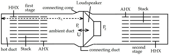
Figure 4.
Schematic of the two-stage engine with loudspeaker coupled in push–pull mode.
For a given acoustic impedance this arrangement should bring the advantage of doubling the acoustic power Wa absorbed by the alternator compared to the one-stage case when considering that, with p1 and p2 being in phase opposition, |p1 − p2| = 2|p| results, and observing that in the one-stage configuration the LA is driven by the pressure acting only on one side [13]. Compared to the one-stage case, however, this arrangement does not allow regulations of the alternator impedance through regulations of the acoustic compliance introduced by the back volume. In the simulations performed by DeltaEC for each working frequency f, the engine parameters (stack location, stack length, loudspeaker location xL) and the loudspeaker parameters (load resistance RL) have been varied in order to find the optimal matching between the LA and the engine. In each run, the peak-to-peak stroke of the diaphragm is fixed to 12 mm while the HHX and AHX lengths are varied, as in the one-stage case, to match exactly the local peak-to-peak acoustic particle amplitude. Furthermore, the distance of the alternator from the AHX (equal on both sides) is modeled to be not lower than 8 cm to allow the accommodation of the alternator in a real technical implementation.
The geometrical dimensions of the engine deriving from the optimization procedure are given in Table 2. Results concerning the TAEG performance are shown in Figure 5 where the efficiencies ηha, ηae, the power values Wa, We, and the impedance parameters |Za|, ϕpU are plotted as a function of f. The graph shows how the TAEG is characterized by a very low efficiency in converting heat to electricity (ηhe ≈ 2% at a maximum with ηha ≈ 3% and ηae ≈ 67.6%) and the maximum obtainable electric output power amounts to We = 35.7 W (with Wa = 54.1 W). Note that in this case the efficiencies ηha, ηae, ηhe are referred to maximum power output. These performance levels are considerably lower than the ones achieved by the one-stage engine previously considered. This result can be interpreted on the basis of the following observations:
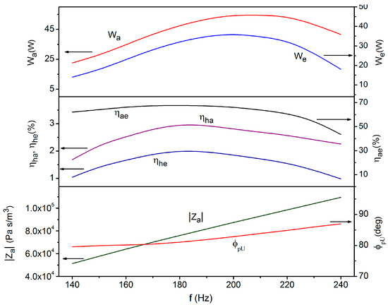
Figure 5.
The power values Wa, We, the efficiencies ηha, ηae, ηhe, and the impedance parameters |Za|, ϕpU as a function of f.
- -
- The LA is installed in a low-impedance region of the standing wave so the acoustic coupling is realized for relatively low values of |Za| (|Za| ≈ 104 Pa s/m3 compared to |Za| ≈ 105 Pa s/m3 of the one-stage case). This entails that at a given working frequency the stroke of the alternator reaches the maximum allowable value |xmax| for low values of the driving pressure |p1 − p2| (|p1 − p2| ≈ 103 Pa compared to |p1| ≈ 104 Pa of the one-stage case). This precludes the stacks from generating high acoustic power levels which scale proportionally to |p|2 [1].
- -
- In both the one-stage and two-stage engine simulations the operation volume velocities are almost equal (|U| ≈ 9 × 10⁻² m3/s). This circumstance derives from having fixed in simulations the peak-to-peak stroke to its maximum allowable value 2|xmax|. So, since the two engines work at comparable operation frequencies, the same volume velocities are involved (|U| = ω Ad xmax).
- -
- The absolute value of the phase angle ϕpU between the driving pressure and the volume velocity for which the impedance matching is realized does not change appreciably with the frequency and is approximately equal in the one-stage and two-stage cases, amounting to around 82°.
These circumstances imply that at a given frequency the two-stage engine performs worse than the one-stage counterpart since it produces a low acoustic power which is poorly absorbed be the LA as stated by the equation
In addition, the optimal load resistances RL for which the impedance matching is realized are not related to the working frequency by the functional dependence shown in Figure 1, which contributes to the degradation of overall performance. The interpretation of the behavior of the efficiencies ηha, ηae with f parallels the one made in the previous subsection.
4.3. Two-Stage Engine with Loudspeaker Coupled in Side Branch Arrangement
As the two-stage engine with push–pull LA is unable to provide the required power output, the LA coupling typology is switched to a side-branch configuration. In this configuration the alternator is placed at the end of a relatively long duct while the other end (the branch input section) is connected to the main engine trunk in sideway (see Figure 6).
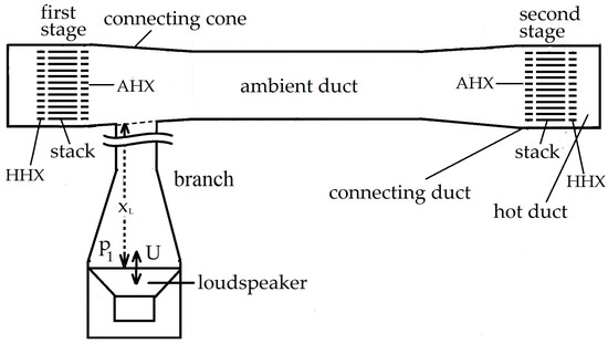
Figure 6.
Schematic of the two-stage engine with loudspeaker coupled in side-branch mode.
The design process of the two-stage TAEG starts by firstly optimizing the branch/LA component. The value of the input acoustic impedance of the optimized branch, Zb = Rb + jXb, is then used in the optimization process of the engine. Making the choice of operating the LA at an acoustic-to-electric conversion efficiency of at least 70%, the plots of Figure 1 allow us to determine the corresponding values of the operation frequency (f = 194.5 Hz) and load resistance (RL = 19 Ω) compatible with the target output power (100 W) and maximum allowable stroke (±6 mm). The driving pressure needed to match the target output power is |p1| ≈ 3 kPa, which corresponds to a volume flow rate amplitude of |U| = 0.0968 m/s).
The branch duct comprise a narrow straight segment, a divergent cone, and a wide straight segment which accommodates the LA/housing assembly (see Figure 7). Geometrical dimensions of the branch should be selected in order the following two conditions be met at the system working frequency:
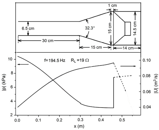
Figure 7.
The pressure and volumetric velocity distributions along the branch to the alternator for f = 194.5 Hz and RL = 19 Ω.
- -
- The impedance at the branch input section should be sufficiently higher than the local trunk impedance to preserve the acoustic wave in the trunk from being distorted and the branch from absorbing too great amounts of power that could lead to unwanted high onset temperatures or, worse, to a not-starting engine. At the same time, the impedance should be not too large to allow the target acoustic power to enter the branch with (as far as possible) low driving pressures (which reduce termoviscous dissipation on the resonator walls proportional to |p|2). So, a trade-off between these two requirements has to be found.
- -
- The impedance at the other side of the branch, where the LA is installed, should match the low impedance of the transducer. The latter can be adjusted, as in the one-stage case, by regulation of the back volume compliance with the aim of decreasing ϕpU. The back volume compliance, however, also affects the input impedance of the branch and this leads again to the issues discussed at the previous point. Hence, also in this case a trade-off between different requirements has to be found.
Selecting the branch configuration in order to create a near λ/4 acoustic field distribution (λ being the sound wavelength) can fulfill both these conditions. This is clearly illustrated in Figure 7 which reports the pressure and velocity distributions along the branch when the pressure amplitude at the input section is about 10 kPa, the module and phase angle of the input impedance of the branch being 2.58 × 10⁵ Pa s/m3 and 44.5°, respectively (Rb = 1.84 × 10⁵ Pa s/m3; Xb = 1.81 × 10⁵ Pa s/m3). The back volume, modeled by a compliance, is adjusted to bring the resonance frequency of the composed LA/housing near the target operation frequency (194.5 Hz). For the selected back volume (equal to 0.0015 m3 after subtraction of the LA volume) the resonance frequency of the LA/housing system is about 187.6 Hz and the phase angle between p1 and U is near 10°. For this configuration, the alternator extracts 100 W of electric power when 153.6 W of acoustic power flow through the branch input section, the peak-to-peak stroke of the loudspeaker being 12 mm.
Using the above values of Rb and Xb the engine is then optimized by varying the stack location, the stack length, and the branch location while adjusting the HXs length to match exactly the local peak-to-peak acoustic particle amplitude. The geometrical dimensions of the engine deriving from the optimization procedure are given in Table 2 (excluding the branch whose dimensions are reported in Figure 8).
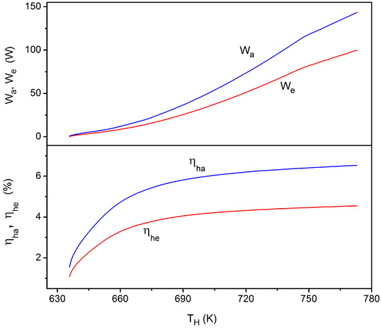
Figure 8.
The power values Wa, We and the efficiencies ηha, ηhe as a function of the heating temperature.
The performance of the engine can be inferred from Figure 8 where the output power values Wa, We and the conversion efficiencies ηha, ηhe are reported as a function of the heating temperature TH which varies as a consequence of heat input change (from 100 to 2200 W by steps of 100 W). In these simulations, the HX lengths were held fixed to the values relative to We = 100 W. From the graph it can be observed how all the investigated parameters grow with TH (reflecting the growth of the stacks conversion efficiency with TH) and that the onset temperature of the engine falls around 360 °C. When the temperature of the HHX reaches 719 K the LA extracts 50 W of electrical power with the design ηae efficiency (70%) and with an overall ηhe efficiency equal to 4.3%. At this operative point the amplitude of the driving pressure in front of the diaphragm and its peak-to-peak stroke amount to 2 × 10³ Pa and 8.7 mm, respectively. When TH = 773 K, the engine produces the target (maximum) power (We = 100 W) with an the overall ηhe efficiency equal to 4.6%. In this case the amplitude of the driving pressure and its peak-to-peak stroke amount to 3 × 10³ Pa and 12 mm, respectively.
Note that the driving pressure is of the same order of magnitude of the driving pressure relative to the two-stage engine with push–pull configuration. In this case, however, the engine is able to achieve the target output power since the use of the branch allows us to decouple the acoustic filed driving the alternator from the one sustained by the trunk where the engine components (stack and HXs) are placed. In this way, the stacks are interested by high pressure levels (which enable high acoustic powers) while the trunk and the back volume regulations concur in selecting a p-U time-phase in front of the LA different from the standing wave phasing (~90°) typical of the trunk, which can be as low as 10°.
5. Conclusions
This paper describes the design methodology of thermoacoustic electricity generators using a standard loudspeaker as a linear alternator. Based on target electrical output power of 50 and 100 W, three standing wave TAEGs working in half-wavelength mode have been conceived with different coupling arrangements of the LA. All the TAEGs models, intended for low-power and low-cost applications, use air at atmospheric pressure as working fluid. Simulation performance by the specialized DeltaEC design tool reveal that the one-stage engine and two-stage engine with LA coupled in a side branch arrangement have comparable efficiencies and are able to meet the target output power values (50 and 100 W, respectively) although they are placed in different impedance locations (high impedance for the first, and low impedance the second). The two-stage engine with LA coupled in push–pull mode is unable to reach the desired performance.
These different behaviors can be explained observing that in the one-stage TAEG the LA is placed in a high-impedance location of the standing wave (|Za| ≈ 105 Pa s/m3). This entails relatively high driving pressures (|p1| ≈ 104 Pa) which, in turn, enable the stack for producing high acoustic power levels. In this case, the phase angle ϕpU is quite high (ϕpU ≈ 82°) as is typical of standing waves.
In the TAEG with LA in a side-branch arrangement the LA is placed in a location with relatively low impedance (|Za| ≈ 104 Pa s/m3), and this entails low driving pressures (|p1| ≈ 103 Pa). In this case, however, the branch decouples the acoustic field driving the alternator from the one sustained by the trunk, allowing the stacks to work under high pressure levels, which enables the production of high acoustic powers. Furthermore, the impedance change operated by the branch and by the compliance associated to the back volume brings a favorable ϕpU near low values (~10°).
In the TAEG with LA in push–pull mode, the LA is also placed in a low-impedance location of the standing wave (|Za| ≈ 104 Pa s/m3) and the driving pressures are low (|p1 − p2| ≈ 103 Pa). As a consequence, the stacks generate a low acoustic power which, with the phase angle ϕpU being quite high (ϕpU ≈ 82°), is poorly absorbed by the LA. In this case, poor impedance matching is realized.
Conflicts of Interest
The author declares no conflict of interest.
References
- Swift, G.W. Thermoacoustic engines. J. Acoust. Soc. Am. 1988, 84, 1145–1180. [Google Scholar] [CrossRef]
- De Blok, C.M. Low operating temperature integral thermoacoustic devices for solar cooling and waste heat recovery. In Proceedings of the Acoustics’08 Conference, Paris, France, 29 June–4 July 2008. [Google Scholar]
- Backhaus, S.; Tward, E.; Petach, M. Traveling-wave thermoacoustic electric generator. Appl. Phys. Lett. 2004, 85, 1085–1087. [Google Scholar] [CrossRef]
- Wu, Z.; Zhang, L.; Dai, W.; Luo, E. Investigation on a 1 kW traveling-wave thermoacoustic electrical generator. Appl. Energy 2014, 124, 140–147. [Google Scholar] [CrossRef]
- Wang, K.; Sun, D.; Zhang, J.; Xu, Y.; Luo, K.; Zhang, N.; Zou, J.; Qiu, L. An acoustically matched traveling-wave thermoacoustic generator achieving 750 W electric power. Energy 2016, 103, 313–321. [Google Scholar] [CrossRef]
- Yu, Z.; Jaworski, A.J.; Backhaus, S. Travelling-wave thermoacoustic electricity generator using an ultra-compliant alternator for utilization of low-grade thermal energy. Appl. Energy 2012, 99, 135–145. [Google Scholar] [CrossRef]
- Kang, H.; Cheng, P.; Yu, Z.; Zheng, H. A two-stage traveling-wave thermoacoustic electric generator with loudspeakers as alternators. Appl. Energy 2015, 137, 9–17. [Google Scholar] [CrossRef]
- Kinsler, L.E.; Frey, A.R.; Coppens, A.B.; Sanders, J.V. Fundamentals of Acoustics, 4th ed.; Wiley: New York, NY, USA, 1982. [Google Scholar]
- Sun, D.M.; Wang, K.; Zhang, X.J.; Guo, Y.N.; Xu, Y.; Qiu, L.M. A traveling-wave thermoacoustic electric generator with a variable electric R-C load. Appl. Energy 2013, 106, 377–382. [Google Scholar] [CrossRef]
- Clark, J.P.; Ward, W.C.; Swift, G.W. Design environment for low-amplitude thermoacoustic energy conversion (DeltaEC). J. Acoust. Soc. Am. 2007, 122, 3014. [Google Scholar] [CrossRef]
- Rott, N. Thermoacoustics. Adv. Appl. Mech. 1980, 20, 135–175. [Google Scholar]
- Swift, G.W. Thermoacoustics: A Unifying Perspective for Some Engines and Refrigerators; Acoustical Society of America: Melville, NY, USA, 2002. [Google Scholar]
- Hamood, A.; Jaworski, A.J.; Mao, X.; Simpson, K. Design and construction of a two-stage thermoacoustic electricity generator with push-pull linear alternator. Energy 2018, 144, 61–72. [Google Scholar] [CrossRef]
© 2018 by the author. Licensee MDPI, Basel, Switzerland. This article is an open access article distributed under the terms and conditions of the Creative Commons Attribution (CC BY) license (http://creativecommons.org/licenses/by/4.0/).