Article

Validity of the Nintendo Wii Balance Board for Kinetic Gait Analysis

1
School of Science for Open and Environmental Systems, Graduate School of Science and Technology, Keio University, 3-14-1 Hiyoshi, Kohoku-ku, Yokohama 223-8522, Japan
2
Department of System Design Engineering, Keio University, 3-14-1 Hiyoshi, Kohoku-ku, Yokohama 223-8522, Japan
*
Author to whom correspondence should be addressed.
Appl. Sci. 2018, 8(2), 285; https://doi.org/10.3390/app8020285
Submission received: 13 January 2018 / Revised: 9 February 2018 / Accepted: 12 February 2018 / Published: 14 February 2018
(This article belongs to the Section Mechanical Engineering)

Abstract

:
The Nintendo Wii Balance Board (WBB) has been suggested as an inexpensive, portable and accessible alternative to costly laboratory-grade force plates for measuring the vertical ground reaction force (vGRF) and center of pressure (COP). Kinetic gait analysis provides important information for the rehabilitation of patients with gait disorders; however, the validity of the WBB for measuring kinetic gait parameters has not been evaluated. Therefore, the purpose of this study is to determine the accuracy of walking force measurements—which change dynamically in a short period of stance time—collected with the WBB. Three healthy adults were asked to walk 10 steps along both straight and curved paths in clockwise (CW) and counterclockwise (CCW) directions while measurements were taken using the WBB and the force plate. The accuracy of the vGRF, COP trajectory, and stance duration were evaluated using the root-mean-square error (RMSE), Pearson’s correlation coefficient and Bland–Altman plots (BAPs) to compare the WBB and the force plate. The results of the vGRF showed high accuracy (r > 0.96 and %RMSE < 6.1% in the mean values), and the stance duration as defined by the vGRF and COP trajectory was equivalent to that of commercial instrumented insoles, which are used as an alternative to the force plates. From these results, we determined that the WBB may be used for kinetic gait analysis in clinical settings where lower accuracy is acceptable.

Graphical Abstract

1. Introduction

The ground reaction force (GRF) and center of pressure (COP)—which is the application point of the GRF during gait—are essential parameters for kinetic gait analyses such as joint torque estimation. Kinetic gait analysis evaluates movement function, which is important for the assessment and rehabilitation of patients with gait disorders such as stroke [1], Parkinson’s disease [2] and osteoarthritis [3].
The GRF and COP are commonly measured using laboratory-grade force plates, which are the gold standard for highly accurate analysis. However, these devices are not always available in general clinical settings (such as a rehabilitation center) because they are expensive, difficult to transport, and require special training for their operation. For these reasons, the Nintendo Wii Balance Board (WBB) (Nintendo, Kyoto, Japan) has been recently suggested as an inexpensive, portable and accessible alternative to the cost-prohibitive force plates [4,5,6,7,8,9,10,11,12]. The WBB can measure uniaxial force and the COP using four force sensors (called strain gauge load cells) located near each of the four corners of the usable surface of the device.
To date, the WBB has mainly been tested as a tool for the assessment of postural instabilities [12,13,14,15,16,17]. Many previous studies have investigated the validity and reliability of using the WBB to measure the COP or its path velocity during static single- and double-leg standing [4,5,6]. In addition, several recent studies have examined the validity of using the WBB to measure weight-bearing asymmetry or the vertical GRF (vGRF) during dynamic motions such as sit-to-stand (squat) [7,8] and ski-jumping [9] tasks.
However, as the device has gained popularity in research, some researchers have argued against its use for postural control [6,10]. The focus of their discussions has been on the uncertainty and reliability across multiple-WBB setups, an inconsistent sample rate and a low signal-to-noise ratio. From these backgrounds, the accuracy of the vGRF and COP trajectory has not been examined for walking. Although walking is a common movement in daily life and is an important task in clinical gait disorder rehabilitation settings, the magnitude of the vGRF and COP positions in a walking stance change more dynamically within a short period of time than they do for other static motions.
Thus, to overcome the limitations of the WBB, calibrating or resampling approaches have been proposed to enhance the measurement accuracy of the COP during static-stance tasks for the assessment of postural sway [6,11]. These techniques are also expected to improve the accuracy during more dynamic tasks.
Therefore, the purpose of this study is to determine the accuracy of the vGRF and COP trajectory measurements taken with the WBB while walking. In the study, we examined the accuracy while people walked along straight and curved paths, because these motions are natural and occur frequently in daily life. In addition, measuring the force distribution in these motions is useful when evaluating potential advantages during the rehabilitation of patients with gait disorders [18,19].

2. Materials and Methods
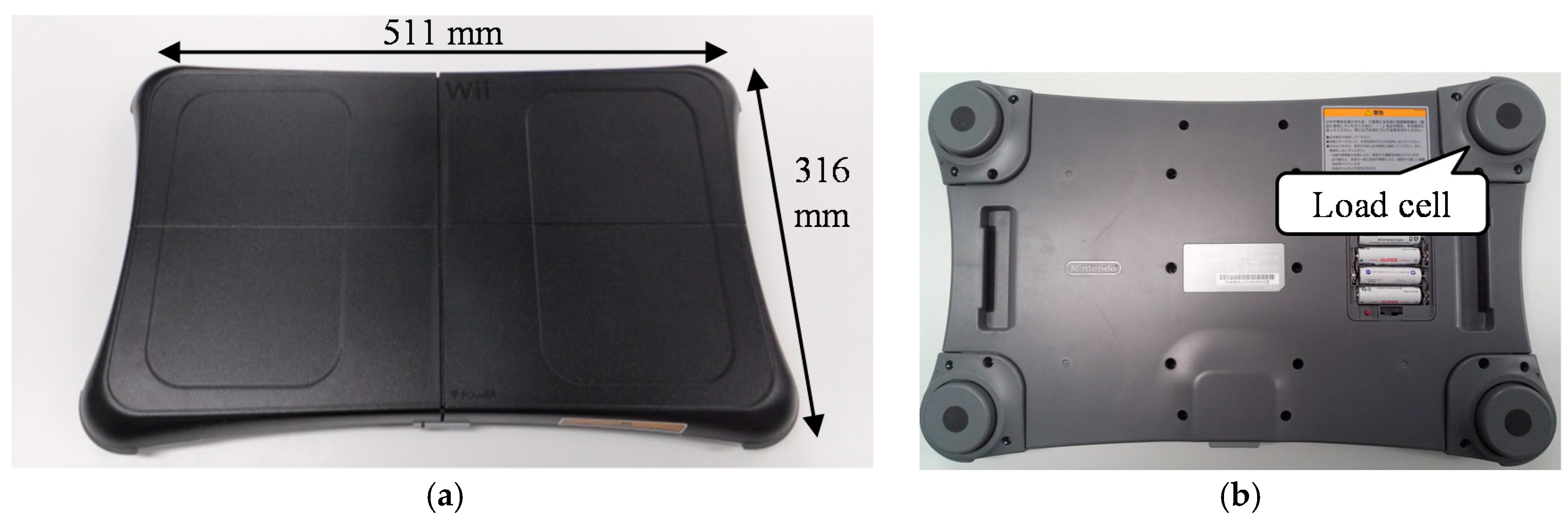
2.1. Device

Two different WBBs were used in this study. The WBB as shown in Figure 1a can measure the vertical force and COP using four strain gauge load cells located near each of the four corners of the device, as shown in Figure 1b.
The devices were connected to a laptop computer using custom software (C++), and data was collected through a Bluetooth connection. The vertical force data from each of the four force sensors, as well as the total vertical force value, were acquired at 100 Hz. The WBBs were placed upon two laboratory-grade force plates (Type 9281E, Kistler, Winterthur, Switzerland) with surfaces of 400 mm × 600 mm in area, which were mounted on the laboratory floor, as shown in Figure 2a. The force plates were operated using a motion capture system (VICON, Oxford, UK), and the data from them contained GRF and COP measurements in the x and y directions, which were obtained at 1000 Hz.
The WBB’s weight applied an initial offset load to both the WBB itself and the force plate. The offset was removed from the WBB measurements when the device was first connected and calibrated by resetting the charge amplifier in the force plates before taking the walking-task measurements.
All the devices were synchronized using a voltage input generated by a microcontroller connected to the laptop through serial communication. To compare the COP positions measured by the WBB and the force plate in the same coordinate system, a transformation matrix adjusted to the coordinates of the devices was made by recording the absolute position of the four edges of the WBB on the force plates using retroreflective markers.

2.2. Procedures

Three healthy adults (ages: 22.3 ± 0.9 years; heights: 1710.7 ± 0.07 mm; body masses: 64.4 ± 9.9 kg) were recruited in this study. All the participants provided informed consent prior to the experiment. They were each asked to perform three walking tasks. The tasks—which included a circle trajectory (1.2 m radius), as shown in Figure 2a,b—were performed in the walkway as follows:
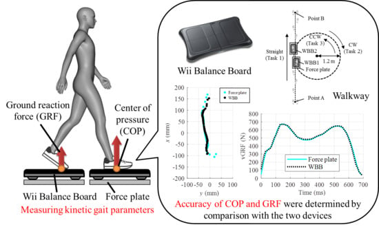
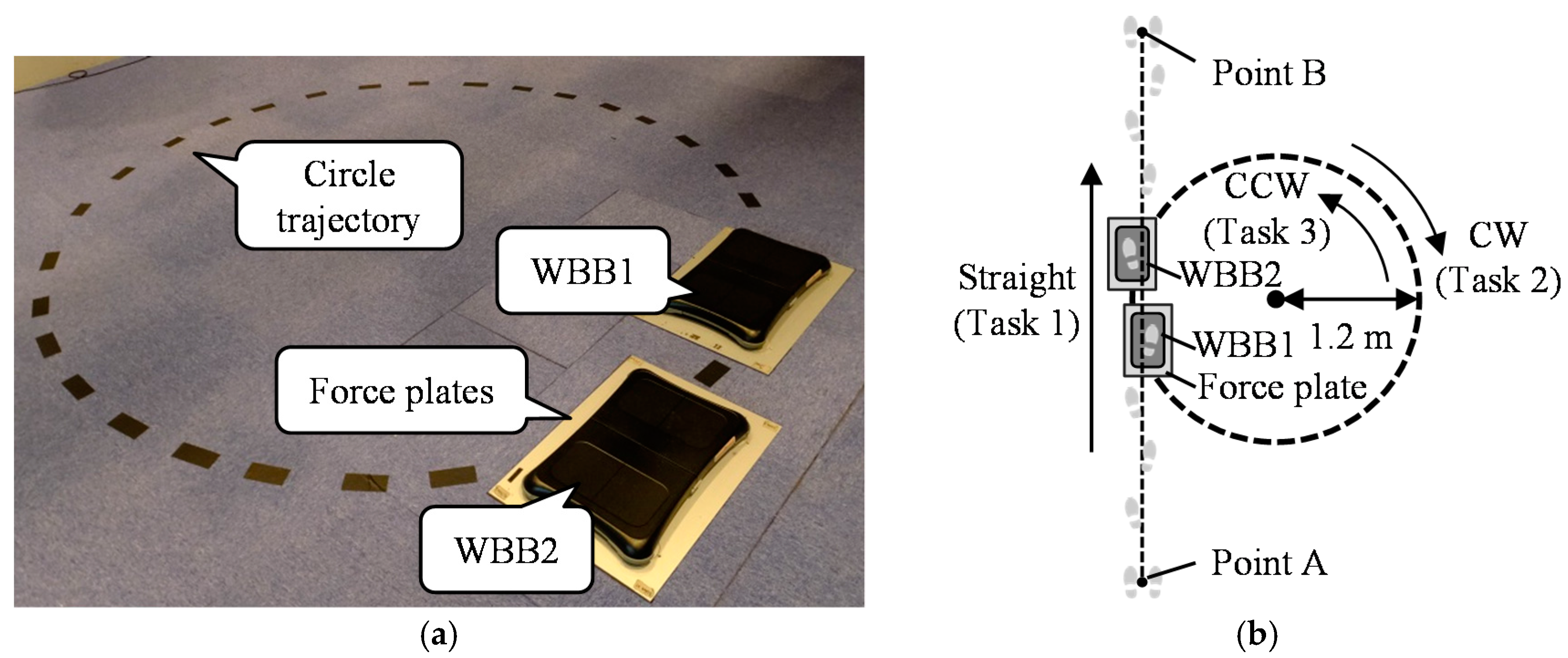
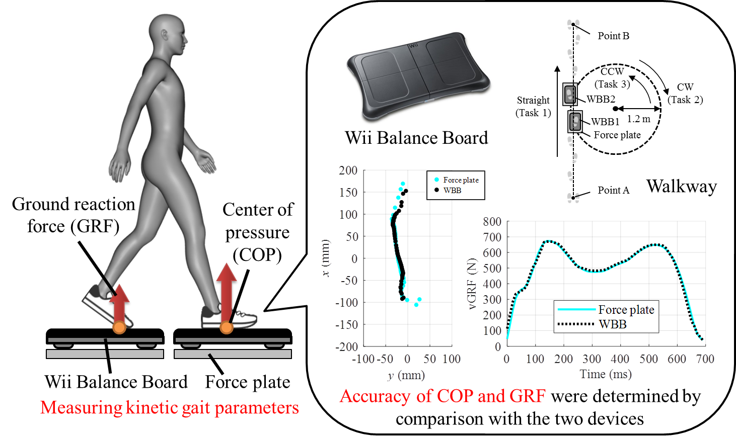
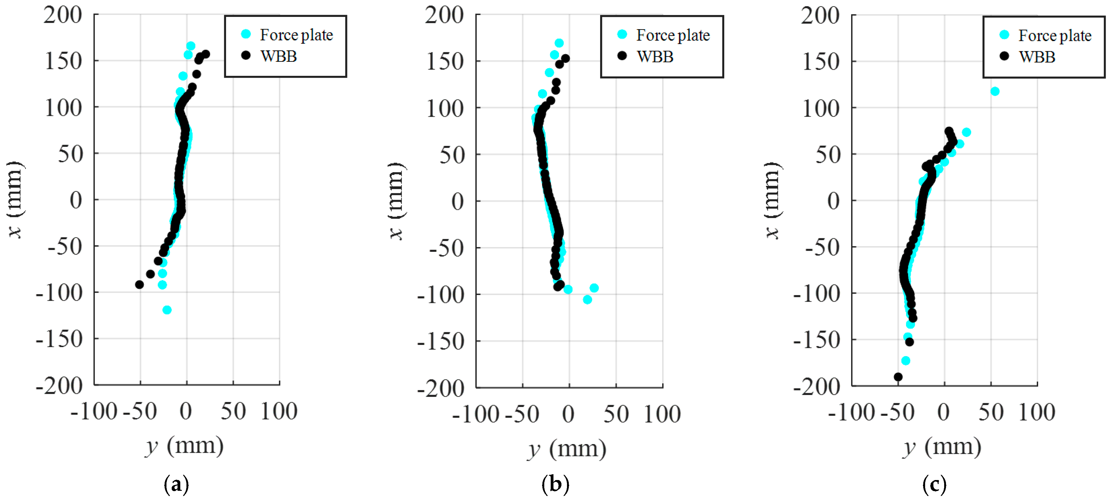
  • The participants walked from point A through the two WBBs and the force plates with their fourth and fifth steps making contact with the devices. Then they kept walking forward and stopped at point B. They each repeated this task 10 times.
  • The participants walked from point A to the devices, similarly to the first task. However, after their steps contacted with both device sets, they started walking along the circle trajectory. Then, they continued along the circle in a clockwise (CW) direction for 11 rounds, before walking through to point B during the final lap.
  • The participants walked from point B to the devices and kept walking on the circle trajectory in a counterclockwise (CCW) direction for 11 rounds, before walking through to point A during the final lap.
The circle trajectory was outlined using tape. The radius length was determined using previous work [20], which proved the length that is adequate to represent the specific features of walking along a curved path [21,22,23]. In all the task executions, the participants walked through the WBB with small steps up, and they were not given specific foot contact positions on the WBB.

2.3. Data Analysis

All of the collected data were analyzed using MATLAB (MathWorks, Natick, MA, USA). Previous studies have reported WBB data collection with different frequencies of acquisition (e.g., 30 [14], 40 [4], 50 [6] and 100 Hz [9,10,11]), which were varied significantly throughout the data acquisition. Moreover, because the WBB has a low signal-to-noise ratio, data from the device has to be filtered. Therefore, we collected data from the WBB at 100 Hz, and then used a moving window filter to smooth the raw data and reduce the noise. A window size of 3 was chosen because it allowed us to average the data from one prior and one posterior frame for smoothing. This size was based on the average sampling frequency of the WBB, as recommended at 63 Hz in the previous study [11].
For the data analysis, a walking stance from both the WBB and the force plate was classified as the time from the heel of the foot’s initial contact (IC) to the time when the toes of the foot came off the ground (TO). The IC and TO were defined as timings for which the force measurement (vGRF) exceeded 5% of each participant’s body mass. Then, the difference in the durations from the two devices was evaluated for each stance.
Next, the data were resampled to compare the vGRF and COP from the force plate with the measurements from the WBB. When there was a difference in the data length between the two devices, the frame numbers were fit to the shorter one. To determine the accuracy of the WBB compared with the force plate, the accuracy of the measured vGRF value was assessed using the %RMSE and Pearson’s correlation coefficient (p < 0.05); the %RMSE, which is the root-mean-square error of the WBB to the force plate divided by each participant’s body mass, was calculated as follows:
% RMSE = 1 N i = 1 N ( F F P i F W B B i ) 2 m × 100
where N is a sample data size in a stance, and FFP and FWBB are the vGRF values measured by the force plates and the WBB, respectively. In addition, Bland–Altman plots (BAPs) were created for the vGRF in the stance. The BAP was created by plotting the difference in vGRF measurements between the two devices against the mean results to examine the relationship between the spread of the error to determine if there was systematic bias. In the study, we used all the sampling data from walking stances to obtain the BAPs.
The COP generated from the WBB measurements was calculated using a weighted average of the location and the measured force value of the four force sensors of the WBB, as shown in the following formula:
C O P X = i = 1 n X i F i i = 1 n F i , C O P Y = i = 1 n Y i F i i = 1 n F i
where n is the number of force sensors, F is a sensor force value, and X and Y are sensor coordinates on the WBB. The sensor coordinates (X, Y) were set as (±216.5, ±119) (in mm), and the center of the WBB was regarded as the origin. These calculations were executed when the total force value of the four sensors exceeded 5% of a participant’s body mass.
The surface of the WBB was located at a height of 53.2 mm from the plane of the force plate. It is difficult to compare the COP trajectory between the two devices precisely because there is a larger horizontal GRF while walking than there is while standing still, and this applies different effects to the COP on the surfaces of the two devices. Thus, the COP trajectory from the force plates were transformed to the WBB’s coordinate system using a transformation matrix generated from the four edge positions of the WBB and the iterative closest point (ICP) algorithm [24]. This algorithm can find a rigid body transformation such that a set of data points can be fitted to a set of model points using least-squares minimization.
To assess the accuracy of the COP values generated from the two devices, the RMSE was calculated in the x (anterior–posterior) and y (mediolateral) directions while a stance was held.
The differences in stance duration, vGRF and COP in the x and y directions between the WBB and the force plates were evaluated per step, and then the mean (± standard deviation) values of 10 steps in the three walking tasks (as previously described) were calculated for each participant.

3. Results

The differences in the stance durations between the two devices are summarized in Table 1. The mean differences of the stance durations for all of the participants were within −17 to 10 ms while straight walking, and between −16 and 24 ms and −19 and 11 ms while walking along a curved path in each direction (CW and CCW, respectively).
To measure the accuracy of the vGRF, Pearson’s correlation coefficient (Table 2) and %RMSE (Table 3) values were calculated, and they revealed agreement between the two devices (r > 0.96 and %RMSE < 6.1% in the mean values). The plots of the vGRF, as measured from the two devices in a stance closest to the mean %RMSE value, are shown in Figure 3.
BAPs of the data from all the tasks for one participant are shown in Figure 4. These results showed no clear relationship between the difference and the mean for the vGRF while walking. The results showed that a few samples measuring small forces had large differences in the vGRF between the two devices, particularly in the straight walking.
The mean (± standard deviations) of the RMSEs of the COP trajectory in the x and y directions are summarized for each task in Table 4, Table 5 and Table 6. The results showed that the RMSEs were within 8 to 24 mm in the x direction and 4 to 7 mm in the y direction while walking straight, within 9 to 19 mm in the x direction and 5 to 9 mm in the y direction while walking CW along the curved path, and within 6 to 12 mm in the x direction and 6 to 18 mm in the y direction while walking CCW along the curved path. The COP trajectories from the two devices in a step with the RMSE value closest to the mean are plotted for each walking task in Figure 5.

4. Discussions

In this study, the accuracy of the stance duration, vGRF and COP trajectory measurements taken from a WBB was assessed by comparison with a laboratory-grade force plate.
For the stance duration, the differences ranged from −31 to 24 ms. These results were equivalent to a foot switch system [25], which can measure IC and end of contact accurately using force sensors placed on the heel and toes of the sole of a foot. The WBB was validated for temporal gait analysis on the basis of the measurement of kinetic parameters. However, the WBB lacks the accuracy to be considered a replacement for the force plates. These differences may be caused by the response delay of the WBB to the dynamic changes in the vGRF upon IC and TO in a walking stance. This insight is supported by the BAP results, which showed large measurement error values when small forces were applied, particularly in straight walking, as shown in Figure 4.
Meanwhile, for the assessment of the vGRF over 400 N, the BAPs revealed a random spread in the error. The result suggests that differences between the measurement devices do not depend on the magnitude of the vGRF in midstance while walking. More importantly, Pearson’s correlation coefficient and %RMSE values for walking in both a straight line and along a curved path were equivalent to those of commercial instrumented insoles [26], which are used as an alternative to the force plates. These results indicate that the WBB is an appropriate tool to measure the vGRF while walking.
When evaluating the accuracy of the COP trajectory, the RMSE values in the x (anterior–posterior) and y (mediolateral) directions, as measured using the WBB, were equivalent to those of the commercial insoles [27], but these values were not equivalent to those of a laboratory-grade device. These errors are thought to be caused by two factors. One is an effect of horizontal GRF, which was difficult to measure using the WBB because it was applied in a different direction to the measurement surface than it was in the force plate, and it had a different height from the floor. The other factor was the inconsistent sampling rate of the WBB. It was particularly difficult for the WBB to trace the force after heel contact and before the end of foot contact, which caused the values of the vGRF to change sharply. The COP trajectory accuracies were reduced in this phase because calculating the COP trajectory depends on the force value.

5. Conclusions

This study has examined the validity of using the WBB to measure kinetic parameters while walking, which is a more dynamic motion than the sit-to-stand and static standing scenarios focused on in previous studies. In comparison to the laboratory-grade force plates, the accuracy of the stance duration, the vGRF and the COP trajectory while walking as measured by the WBB were evaluated. From the results, although it did not have satisfactory accuracy to be considered a replacement of laboratory-grade devices, the WBB may be used to take measurements in clinical settings for which lower accuracy is acceptable. In particular, the vGRF, for which the WBB showed a high accuracy compared with the force plate, is equivalent to the commercial instrumented insoles used as an alternative to the laboratory-grade devices.
Further investigation is required to test individual variability in the measured force among multiple devices while walking, because this has not been considered in dynamic motions. In addition, future work should examine the static and dynamic calibration of the WBB to obtain a more accurate COP trajectory in dynamic motions, as determined from previous studies [11]. When clinicians use the WBB for gait analysis, some specifications of the WBB have to be considered, such as contact positions of the foot, because the WBB has a significant increase in COP error from the center to the corner locations [10]. Moreover, the WBB has a low height (53.2 mm), and the device needs to be set to its usable surface at the same level as the walking floor in order to prevent stumbling in clinical settings.

Acknowledgments

This study was supported by JSPS KAKENHI, Grant No. 16H04290, and JKA and its promotion funds from KEIRIN RACE (28-143).

Author Contributions

Ryo Eguchi and Masaki Takahashi conceived and designed the proposed method and the verification experiments; Ryo Eguchi performed the experiments and wrote the paper.

Conflicts of Interest

The authors declare no conflict of interest.

References

  1. Leroux, A.; Pinet, H.; Nadeau, S. Task-oriented intervention in chronic stroke—Changes in clinical and laboratory measures of balance and mobility. Am. J. Phys. Med. Rehabil. 2006, 85, 820–830. [Google Scholar] [CrossRef] [PubMed]
  2. Hass, C.J.; Waddell, D.E.; Fleming, R.P.; Juncos, J.L.; Gregor, R.J. Gait initiation and dynamic balance control in Parkinson’s disease. Arch. Phys. Med. Rehabil. 2005, 86, 2172–2176. [Google Scholar] [CrossRef] [PubMed]
  3. Van den Noort, J.C.; Van der Esch, M.; Steultjens, M.P.M.; Dekker, J.; Schepers, H.M.; Veltink, P.H.; Harlaar, J. The knee adduction moment measured with an instrumented force shoe in patients with knee osteoarthritis. J. Biomech. 2012, 45, 281–288. [Google Scholar] [CrossRef] [PubMed]
  4. Clark, R.A.; Bryant, A.L.; Pua, Y.H.; McCrory, P.; Bennell, K.; Hunt, M. Validity and reliability of the Nintendo Wii Balance Board for assessment of standing balance. Gait Posture 2010, 31, 307–310. [Google Scholar] [CrossRef] [PubMed]
  5. Huurnink, A.; Fransz, D.P.; Kingma, I.; van Dieen, J.H. Comparison of a laboratory grade force platform with a Nintendo Wii Balance Board on measurement of postural control in single-leg stance balance tasks. J. Biomech. 2013, 46, 1392–1395. [Google Scholar] [CrossRef] [PubMed]
  6. Leach, J.M.; Mancini, M.; Peterka, R.J.; Hayes, T.L.; Horak, F.B. Validating and calibrating the Nintendo Wii balance board to derive reliable center of pressure measures. Sensors 2014, 14, 18244–18267. [Google Scholar] [CrossRef] [PubMed]
  7. Yamako, G.; Chosa, E.; Totoribe, K.; Fukao, Y.; Deng, G. Quantification of the sit-to-stand movement for monitoring age-related motor deterioration using the Nintendo Wii Balance Board. PLoS ONE 2017, 12, e0188165. [Google Scholar] [CrossRef] [PubMed]
  8. Abujaber, S.; Gillispie, G.; Marmon, A.; Zeni, J. Validity of the Nintendo Wii Balance Board to assess weight bearing asymmetry during sit-to-stand and return-to-sit task. Gait Posture 2015, 41, 676–682. [Google Scholar] [CrossRef] [PubMed]
  9. Yamamoto, K.; Matsuzawa, M. Validity of a jump training apparatus using Wii Balance Board. Gait Posture 2013, 38, 132–135. [Google Scholar] [CrossRef] [PubMed]
  10. Bartlett, H.L.; Ting, L.H.; Bingham, J.T. Accuracy of force and center of pressure measures of the Wii Balance Board. Gait Posture 2014, 39, 224–228. [Google Scholar] [CrossRef] [PubMed]
  11. Audiffren, J.; Contal, E. Preprocessing the Nintendo Wii board signal to derive more accurate descriptors of statokinesigrams. Sensors 2016, 16, 1208. [Google Scholar] [CrossRef] [PubMed]
  12. Scaglioni-Solano, P.; Aragon-Vargas, L.F. Validity and reliability of the Nintendo Wii Balance Board to assess standing balance and sensory integration in highly functional older adults. Int. J. Rehabil. Res. 2014, 37, 138–143. [Google Scholar] [CrossRef] [PubMed]
  13. Clark, R.A.; McGough, R.; Paterson, K. Reliability of an inexpensive and portable dynamic weight bearing asymmetry assessment system incorporating dual Nintendo Wii Balance Boards. Gait Posture 2011, 34, 288–291. [Google Scholar] [CrossRef] [PubMed]
  14. Koslucher, F.; Wade, M.G.; Nelson, B.; Lim, K.; Chen, F.C.; Stoffregen, T.A. Nintendo Wii Balance Board is sensitive to effects of visual tasks on standing sway in healthy elderly adults. Gait Posture 2012, 36, 605–608. [Google Scholar] [CrossRef] [PubMed]
  15. Wikstrom, E.A. Validity and reliability of Nintendo Wii Fit balance scores. J. Athl. Train. 2012, 47, 306–313. [Google Scholar] [CrossRef] [PubMed]
  16. Holmes, J.D.; Jenkins, M.E.; Johnson, A.M.; Hunt, M.A.; Clark, R.A. Validity of the Nintendo Wii® balance board for the assessment of standing balance in Parkinson’s disease. Clin. Rehabil. 2013, 27, 361–366. [Google Scholar] [CrossRef] [PubMed]
  17. Severini, G.; Straudi, S.; Pavarelli, C.; Da Roit, M.; Martinuzzi, C.; Pizzongolo, L.D.; Basaglia, N. Use of Nintendo Wii Balance Board for posturographic analysis of Multiple Sclerosis patients with minimal balance impairment. J. Neuroeng. Rehabil. 2017, 14, 19. [Google Scholar] [CrossRef] [PubMed]
  18. Guglielmetti, S.; Nardone, A.; De Nunzio, A.M.; Godi, M.; Schieppati, M. Walking along circular trajectories in Parkinson’s disease. Mov. Disord. 2009, 24, 598–604. [Google Scholar] [CrossRef] [PubMed]
  19. Godi, M.; Nardone, A.; Schieppati, M. Curved walking in hemiparetic patients. J. Rehabil. Med. 2010, 42, 858–865. [Google Scholar] [CrossRef] [PubMed]
  20. Godi, M.; Turcato, A.M.; Schieppati, M.; Nardone, A. Test-retest reliability of an insole plantar pressure system to assess gait along linear and curved trajectories. J. Neuroeng. Rehabil. 2014, 11, 95. [Google Scholar] [CrossRef] [PubMed]
  21. Courtine, G.; Schieppati, M. Human walking along a curved path. I. Body trajectory, segment orientation and the effect of vision. Eur. J. Neurosci. 2003, 18, 177–190. [Google Scholar] [CrossRef] [PubMed]
  22. Courtine, G.; Schieppati, M. Human walking along a curved path. II. Gait features and EMG patterns. Eur. J. Neurosci. 2003, 18, 191–205. [Google Scholar] [CrossRef] [PubMed]
  23. Courtine, G.; Schieppati, M. Tuning of a basic coordination pattern constructs straight-ahead and curved walking in humans. J. Neurophysiol. 2004, 91, 1524–1535. [Google Scholar] [CrossRef] [PubMed]
  24. Bergstrom, P.; Edlund, O. Robust registration of point sets using iteratively reweighted least squares. Comput. Optim. Appl. 2014, 58, 543–561. [Google Scholar] [CrossRef]
  25. Hausdorff, J.M.; Ladin, Z.; Wei, J.Y. Footswitch system for measurement of the temporal parameters of gait. J. Biomech. 1995, 28, 347–351. [Google Scholar] [CrossRef]
  26. Hurkmans, H.L.P.; Bussmann, J.B.J.; Selles, R.W.; Horemans, H.L.D.; Benda, E.; Stam, H.J.; Verhaar, J.A.N. Validity of the Pedar Mobile system for vertical force measurement during a seven-hour period. J. Biomech. 2006, 39, 110–118. [Google Scholar] [CrossRef] [PubMed]
  27. Chesnin, K.J.; Selby-Silverstein, L.; Besser, M.P. Comparison of an in-shoe pressure measurement device to a force plate: Concurrent validity of center of pressure measurements. Gait Posture 2000, 12, 128–133. [Google Scholar] [CrossRef]
Figure 1. Appearance of the Nintendo Wii Balance Board (WBB): (a) usable surface of the device, and (b) four load cells of the WBB located near the four corners (bottom view of the device).
Applsci 08 00285 g001
Figure 2. Experimental walkway including two Nintendo Wii Balance Boards (WBBs) and force plates. (a) Actual setup; (b) schematic walkway and walking directions of each task.
Applsci 08 00285 g002
Figure 3. Vertical ground reaction force (vGRF) measured from the Nintendo Wii Balance Board (WBB) and the force plate in a stance while (a) walking straight (right foot—RF), and (b) walking along a curved path in a clockwise (CW) direction (RF (IN—inside foot turning)).
Applsci 08 00285 g003
Figure 4. Bland–Altman plots showing the comparison between the force plates and the Nintendo Wii Balance Board (WBB). (a) Data from 10 steps walking straight (right foot—RF). (b) Data from 10 steps walking clockwise (CW) along the curved path (RF (IN—inside foot turning)).
Applsci 08 00285 g004
Figure 5. Center of pressure (COP) measured from the Nintendo Wii Balance Board (WBB) and the force plate in a stance while (a) walking straight (right foot—RF), (b) walking along a curved path in clockwise (CW) direction (RF (IN—inside foot turning)), and (c) walking along a curved path in counterclockwise (CCW) direction (RF (OUT—outside foot turning)).
Applsci 08 00285 g005
Table 1. Root-mean-square (RMS) differences in stance duration measurements between the Nintendo Wii Balance Board (WBB) and the force plate.
SubjectStraight Walking (ms)Curved Walking (ms)
CWCCW
LFRFLF (OUT)RF (IN)LF (IN)RF (OUT)
A4.7 (±8.8)−4.1 (±7.9)4.5 (±6.3)0.0 (±8.1)−7.5 (±6.6)−9.9 (±8.3)
B9.6 (±7.3)8.8 (±8.2)−16.0 (±7.9)−14.2 (±4.4)−1.9 (±6.9)0.0 (±6.2)
C3.5 (±5.3)−1.2 (±4.4)7.5 (±6.2)−0.7 (±6.2)−10.1 (±4.1)−18.3 (±7.6)
RF: right foot; LF: left foot; IN: inside foot turning; OUT: outside foot turning. The WBB1 measured steps of RF in straight walking and RF (IN) of clockwise (CW) and LF (IN) of counterclockwise (CCW) in curved walking.
Table 2. Root-mean-square error (%RMSE) of measured vertical ground reaction force (vGRF) comparing the Nintendo Wii Balance Board (WBB) to the force plate.
SubjectStraight Walking (%)Curved Walking (%)
CWCCW
LFRFLF (OUT)RF (IN)LF (IN)RF (OUT)
A2.7 (±0.6)2.5 (±0.6)3.9 (±1.5)2.4 (±0.8)3.1 (±1.2)4.2 (±1.8)
B3.5 (±1.7)3.2 (±1.5)5.2 (±1.6)4.1 (±1.5)2.6 (±0.8)2.6 (±0.5)
C3.4 (±0.7)3.6 (±0.6)4.0 (±1.7)2.8 (±1.3)5.2 (±1.5)6.1 (±2.1)
Table 3. Pearson’s correlation coefficient of vertical ground reaction force (vGRF) measured from the Nintendo Wii Balance Board (WBB) and the force plate.
SubjectStraight WalkingCurved Walking
CWCCW
LFRFLF (OUT)RF (IN)LF (IN)RF (OUT)
A0.9940.9960.9880.9960.9910.985
B0.9880.9920.9760.9870.9940.996
C0.9920.9910.9870.9940.9770.968
Table 4. Root-mean-square error (RMSE) of center of pressure (COP) comparing measurements from the Nintendo Wii Balance Board (WBB) with those from the force plate while walking straight.
SubjectLFRF
x (mm)y (mm)x (mm)y (mm)
A11.5 (±8.5)5.3 (±1.1)8.5 (±2.1)4.2 (±0.8)
B9.9 (±2.8)7.5 (±0.9)8.3 (±3.3)6.3 (±1.3)
C9.8 (±2.6)7.7 (±1.7)10.1 (±2.9)6.3 (±1.4)
Table 5. Root-mean-square error (RMSE) of center of pressure (COP) comparing measurements from the Nintendo Wii Balance Board (WBB) with those from the force plate while walking along the curved path (clockwise—CW).
SubjectLF (OUT)RF (IN)
x (mm)y (mm)x (mm)y (mm)
A12.3 (±5.0)6.5 (±1.1)9.2 (±1.9)7.2 (±1.9)
B16.3 (±3.4)6.0 (±0.9)12.5 (±7.6)8.0 (±1.7)
C13.1 (±5.0)8.6 (±2.7)12.6 (±11.9)7.9 (±3.3)
Table 6. Root-mean-square error (RMSE) of center of pressure (COP) comparing measurements from the Nintendo Wii Balance Board (WBB) with those from the force plate while walking along the curved path (counterclockwise—CCW).
SubjectLF (IN)RF (OUT)
x (mm)y (mm)x (mm)y (mm)
A17.6 (±4.5)7.6 (±1.0)6.9 (±1.7)7.5 (±1.4)
B15.1 (±6.4)10.1 (±3.5)7.3 (±1.5)6.0 (±1.1)
C15.0 (±2.2)8.1 (±1.3)10.4 (±3.7)8.3 (±1.2)

