Fatigue of Friction Stir Welded Aluminum Alloy Joints: A Review

Abstract
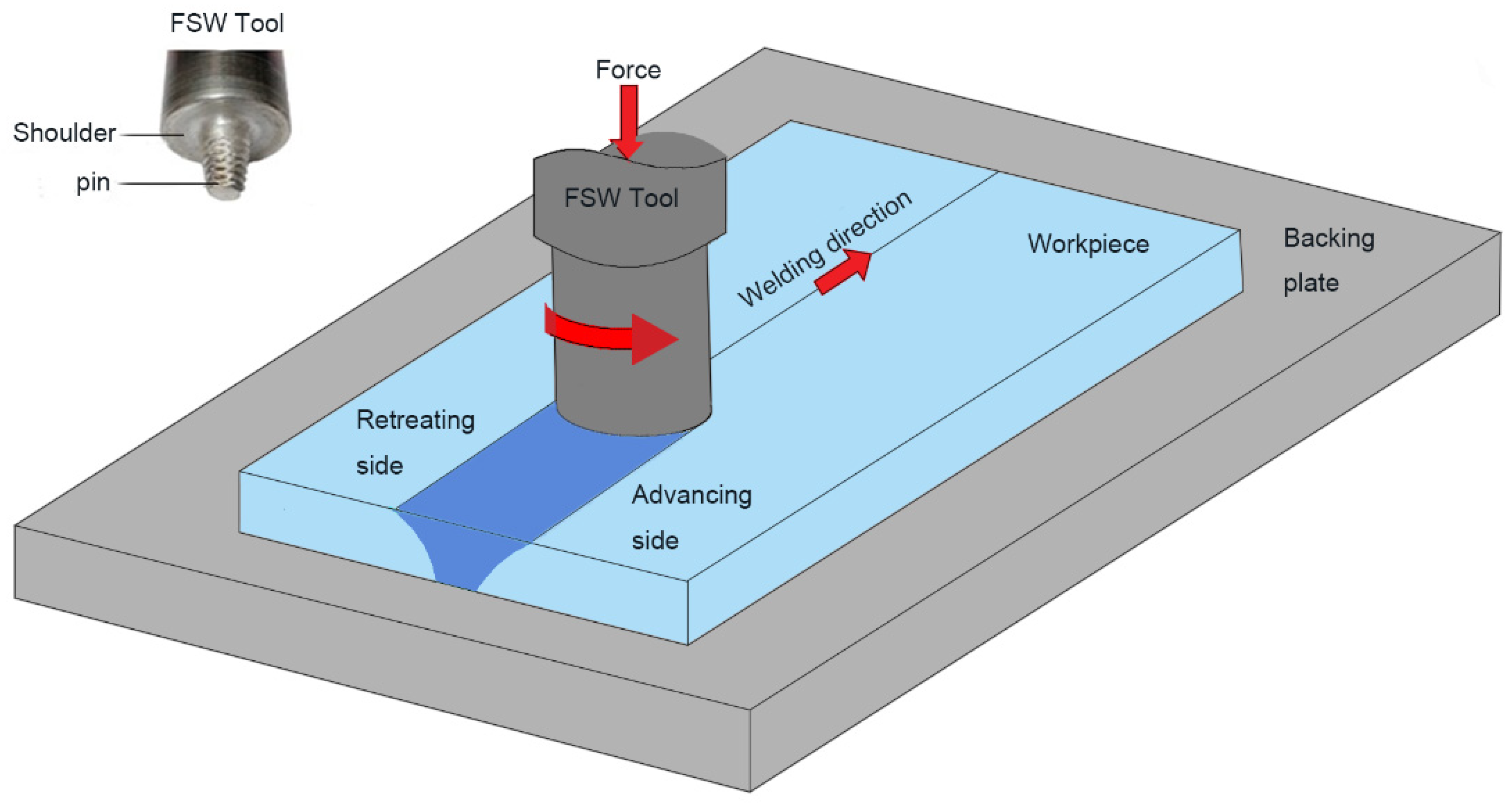
:1. Introduction
2. Fatigue Failure Mechanism of FSW Weld
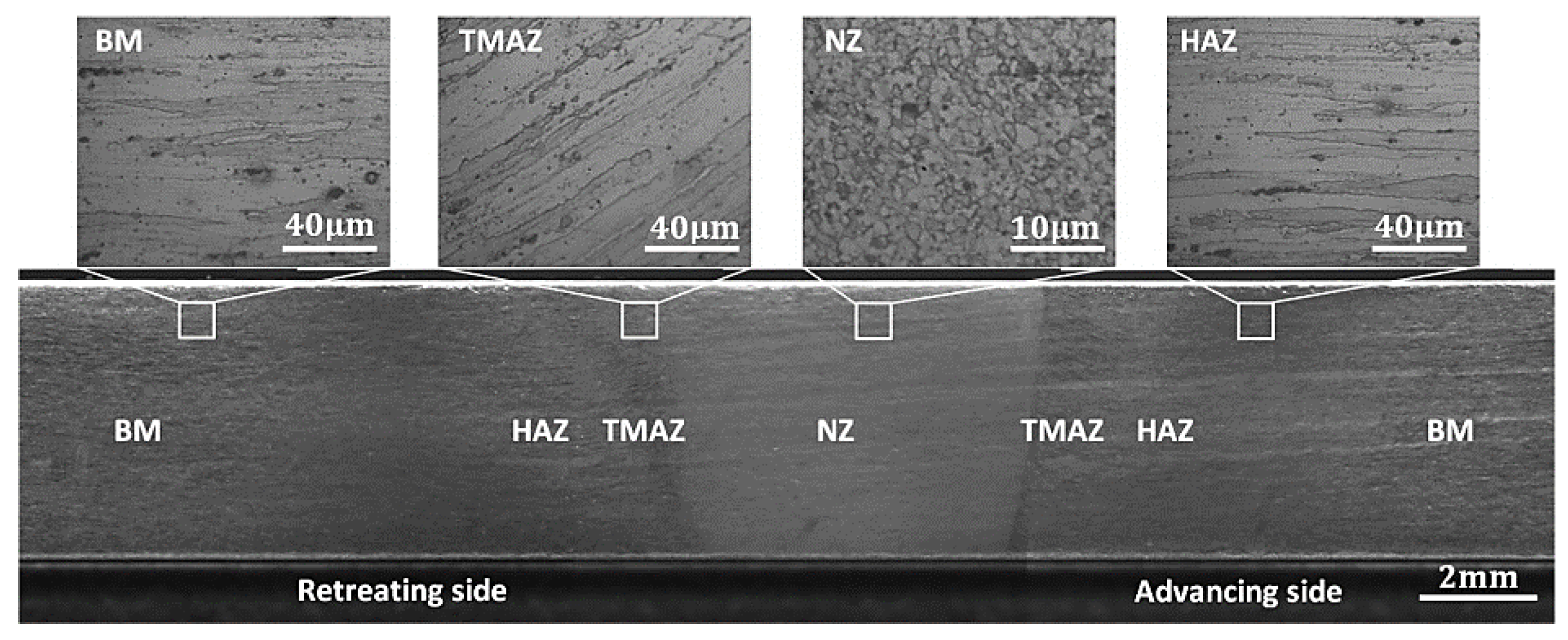
2.1. Characteristics of Weld Zones
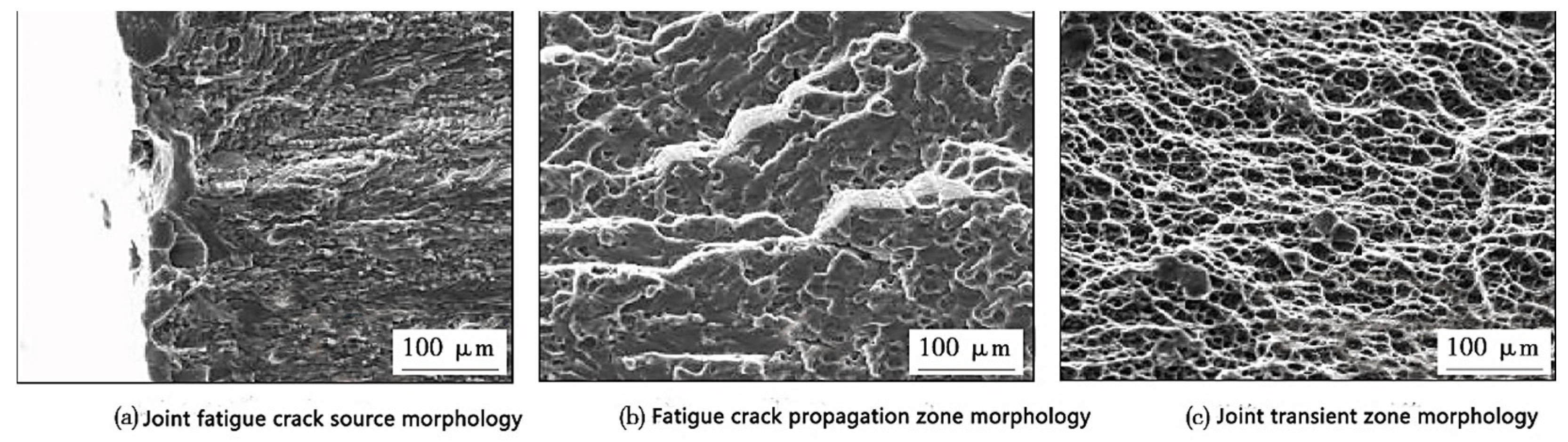
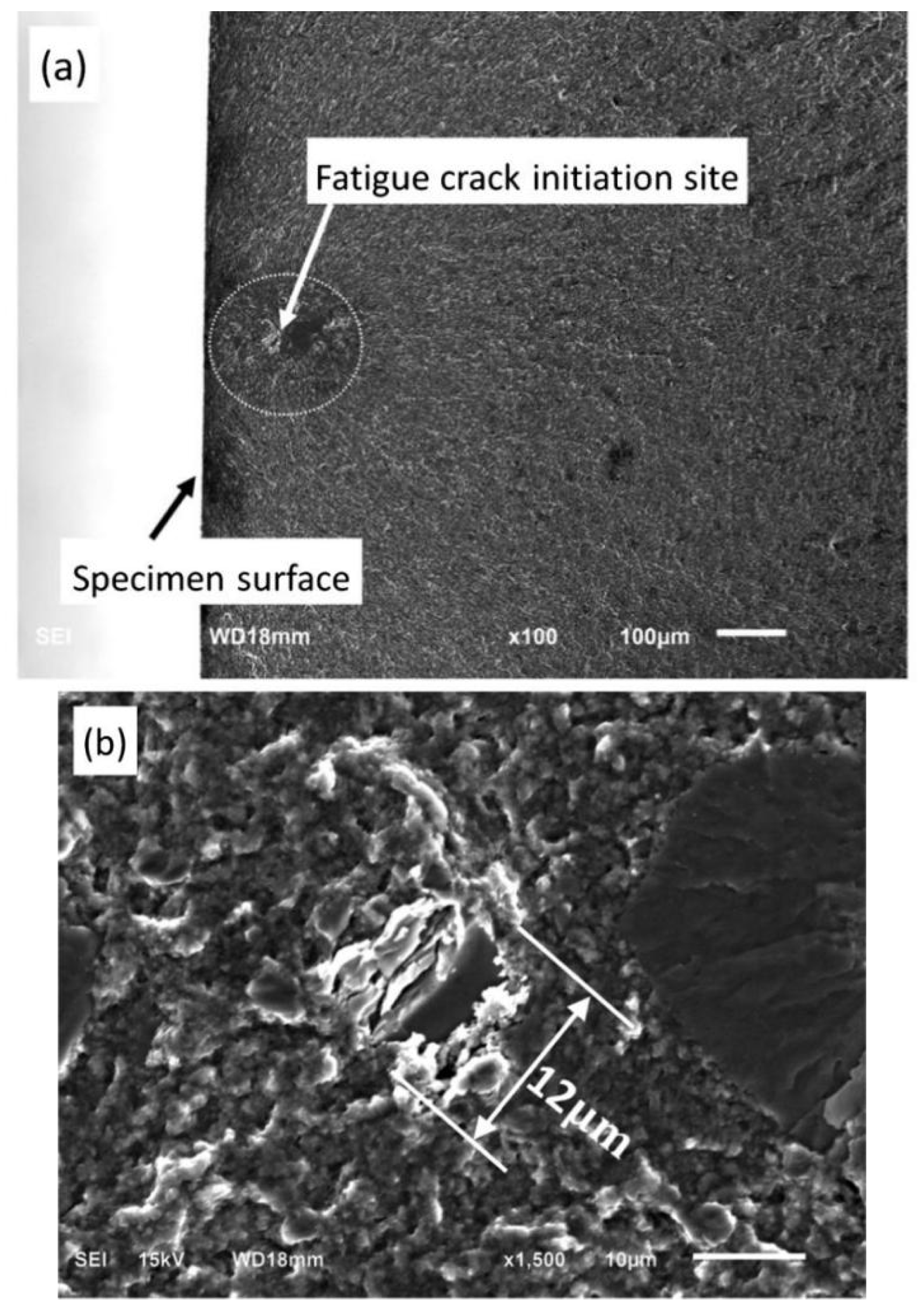
2.2. Fractography
3. Factors Affecting Fatigue Performance
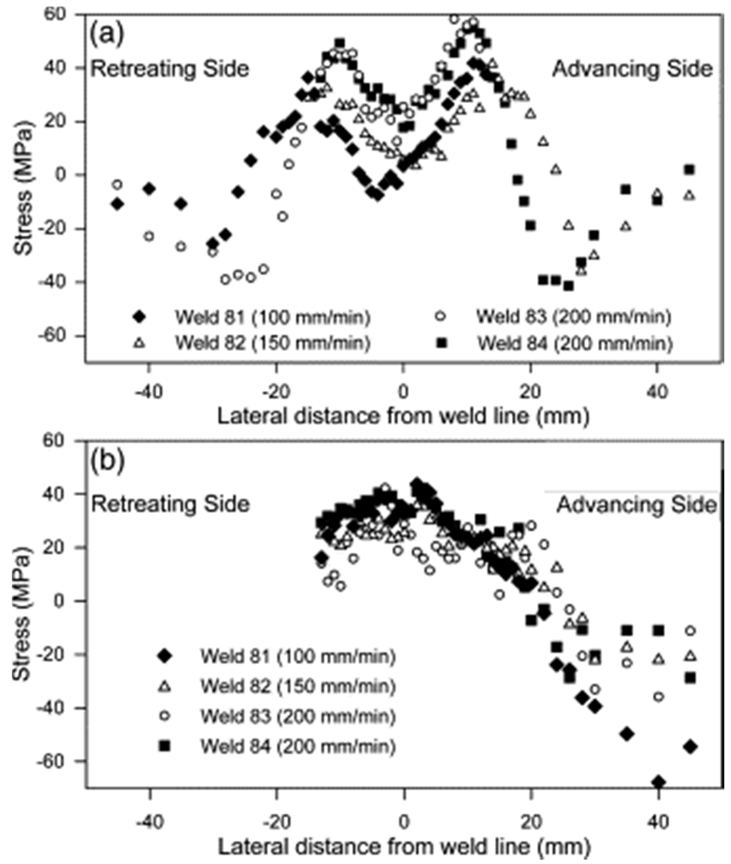
3.1. Process Parameters
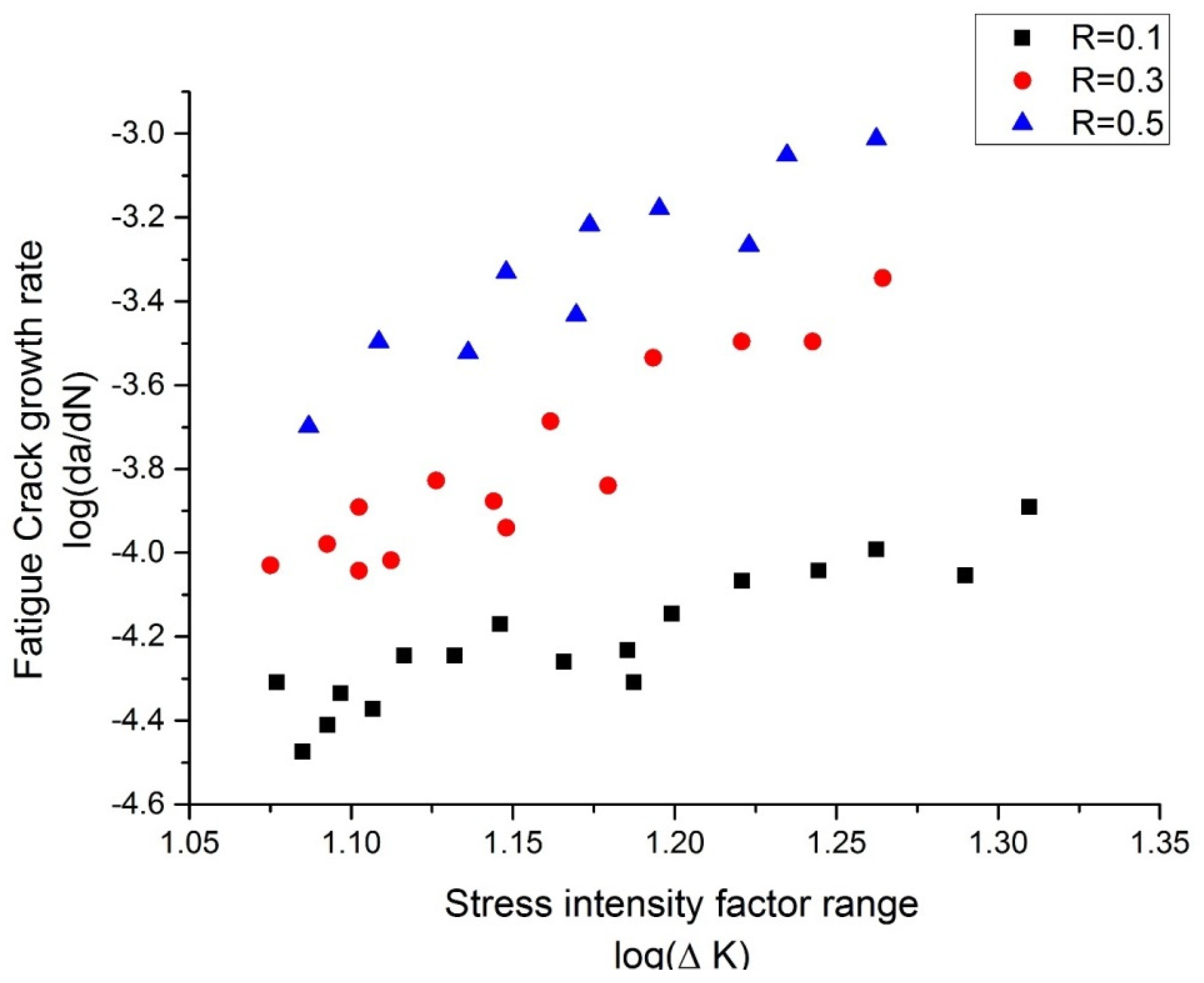
3.2. Stress Ratio
3.3. Test Environment
3.4. Residual Stress
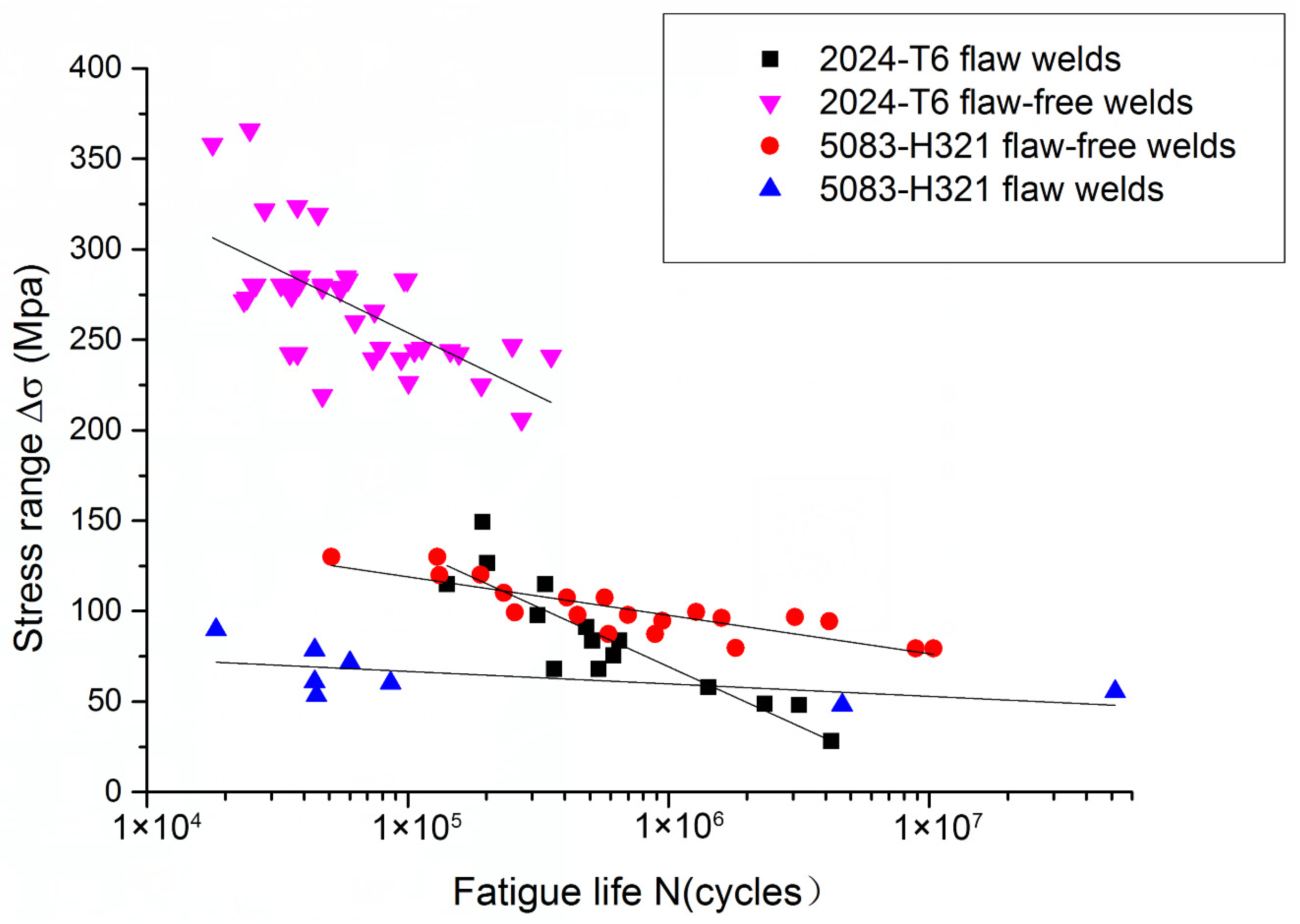
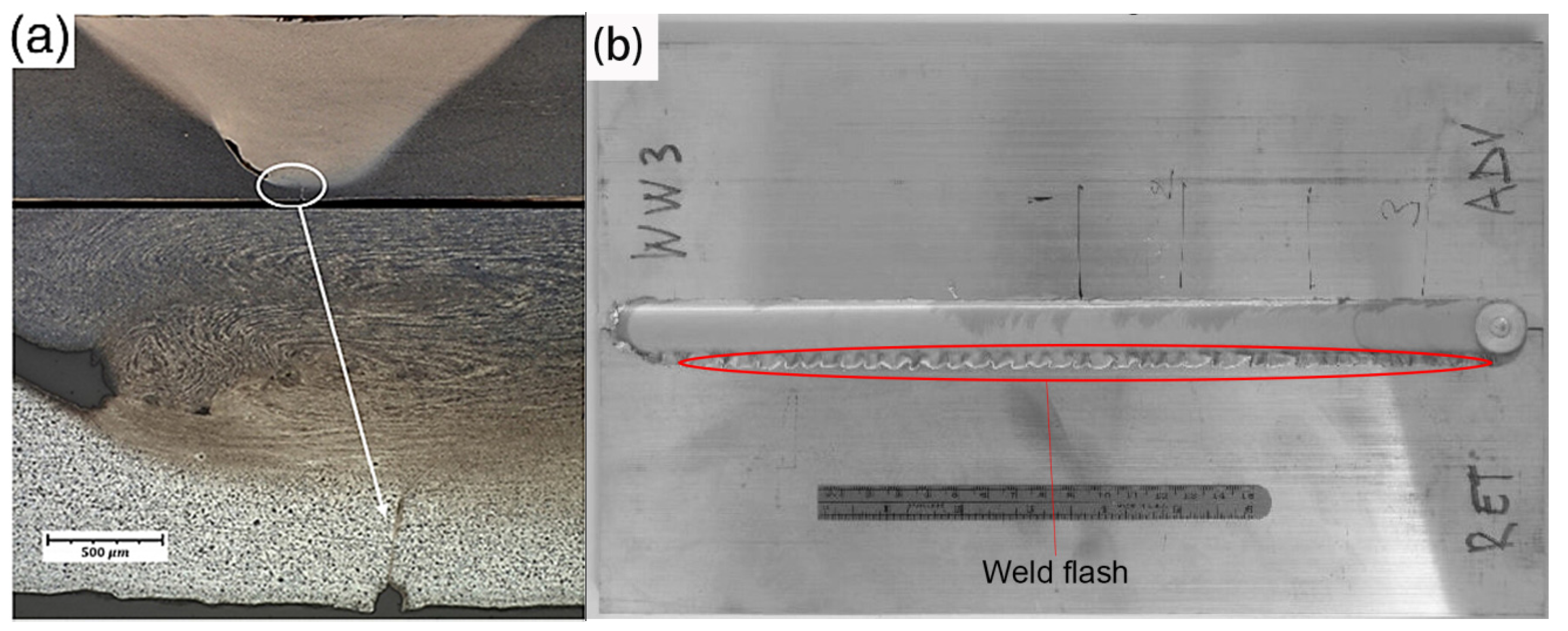
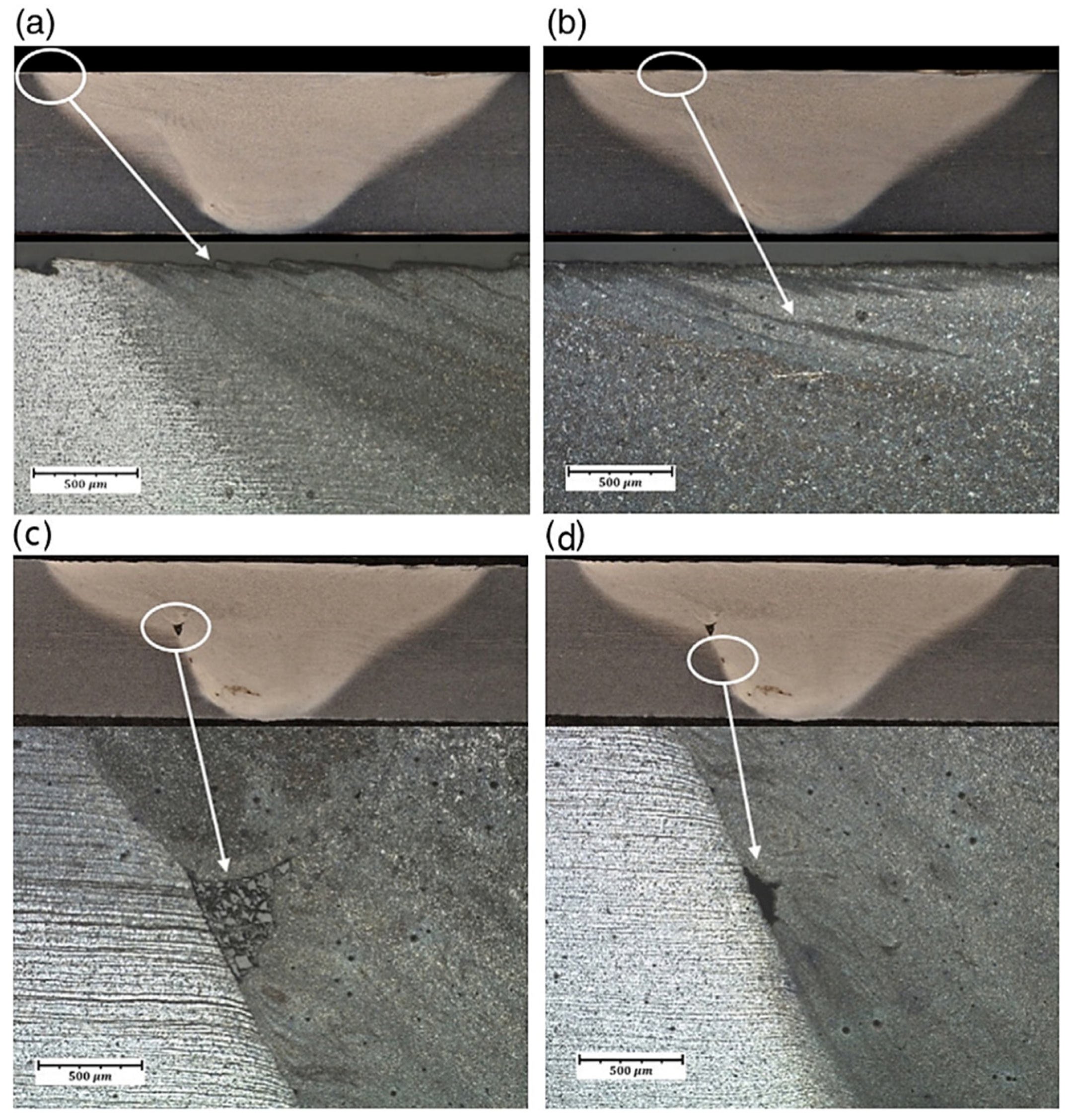
3.5. Weld Defects
4. Crack Growth Rate
5. Fatigue Life of Friction Stir Welded Joints
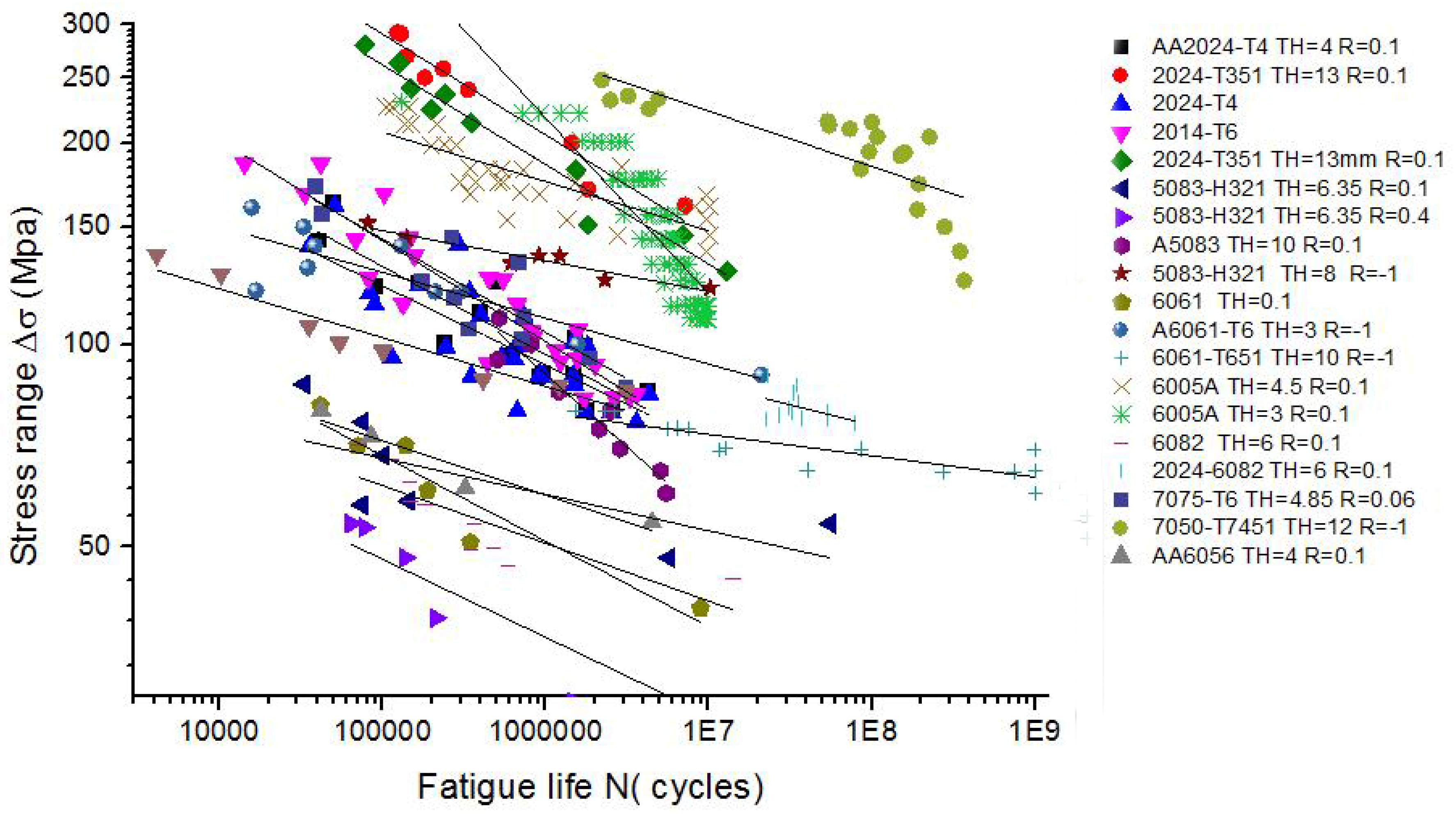
5.1. The Stress Cycle (SN) Analysis
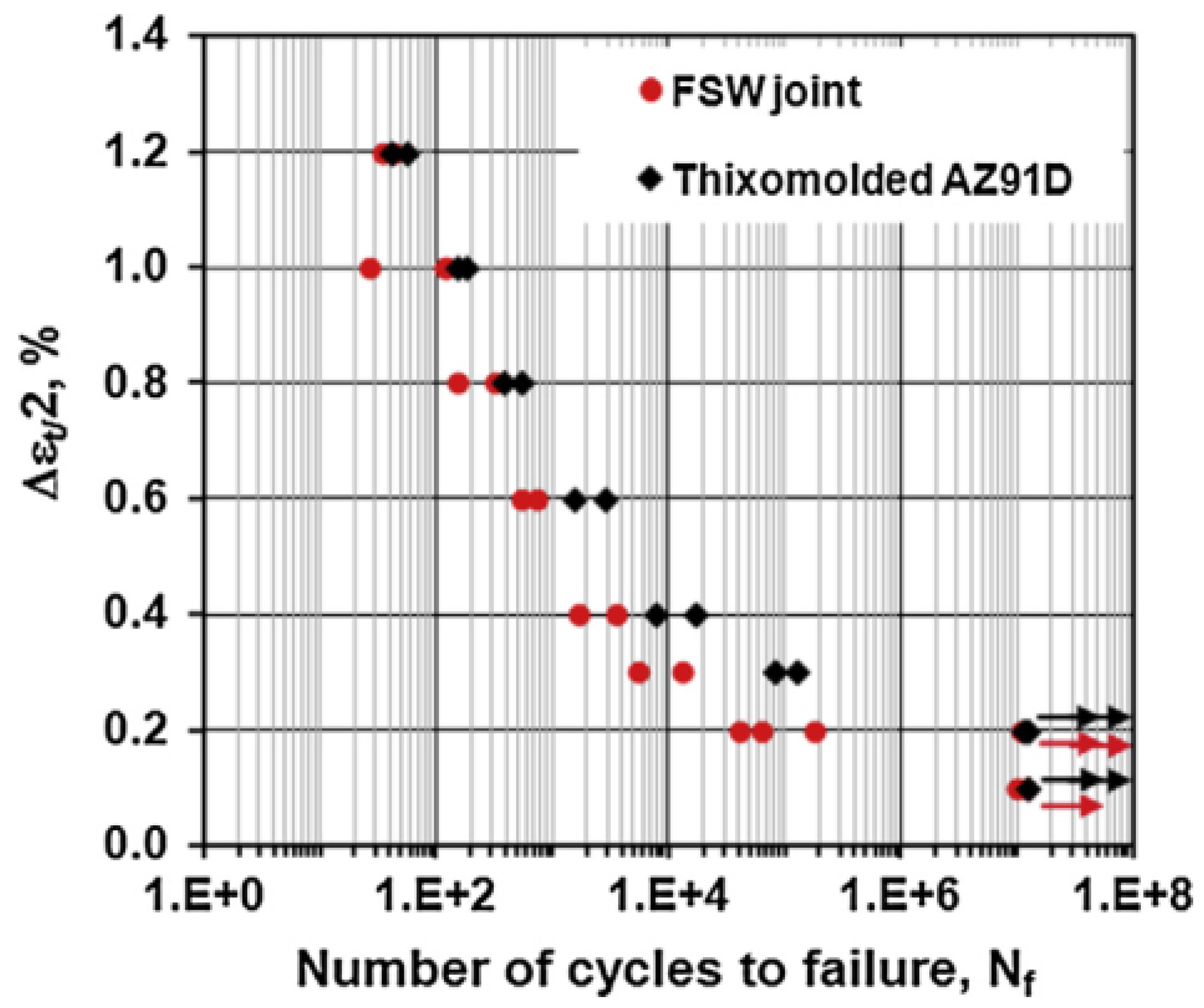
5.2. The Strain Cycle (EN) Analysis
6. Experimental Techniques
7. Conclusions
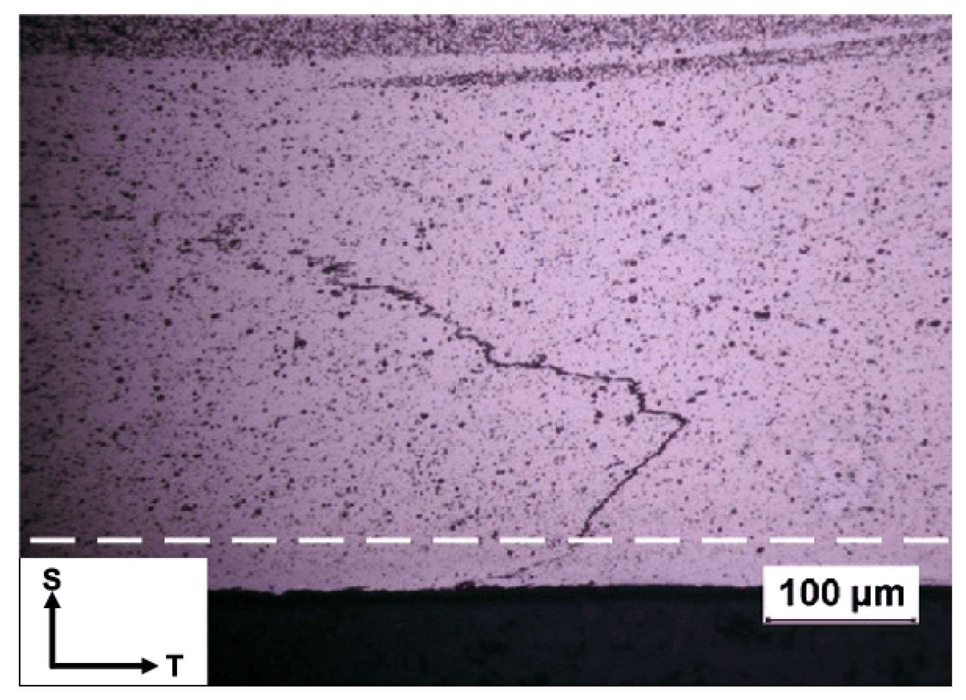
- The fatigue crack initiation generally started at the surface of the weld, due to the fact that FSW welds with optimized process parameters do not contain internal defects or flaws. In addition, the initiation site was mainly located between the TMAZ and the HAZ as a result of both high temperature and plastic deformation. The difference in hardness between the TMAZ and HAZ resulted in a weak zone, which is vulnerable to the formation of local slip bands.
- The fatigue performance of FSW joints is mainly affected by process parameters, stress ratio, environment, residual stress, defects, and so on. The process parameters can be optimized to increase the weld fatigue life. Residual stress has a large influence on the crack growth rate, and it is difficult to remove when the welds are complex. The effect of defects on the fatigue properties of materials is complicated and depends on the type of defects.
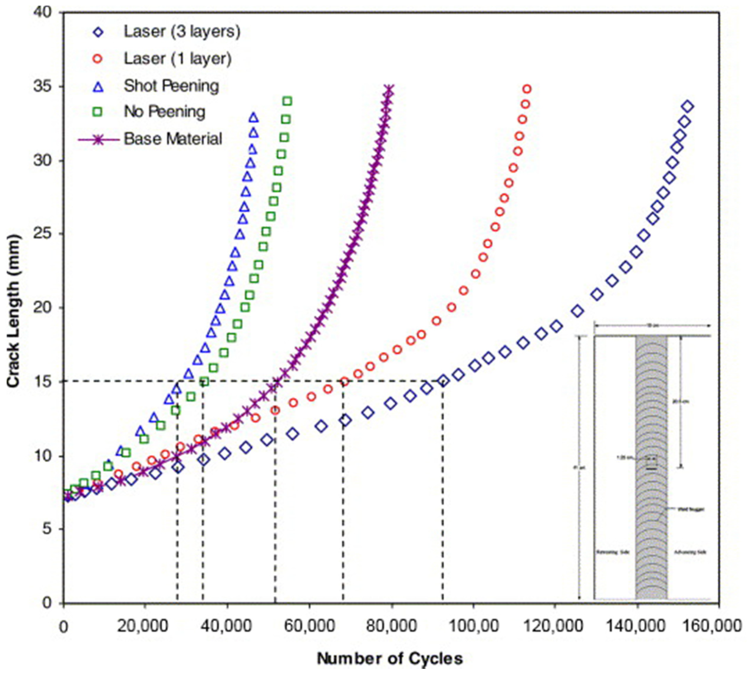
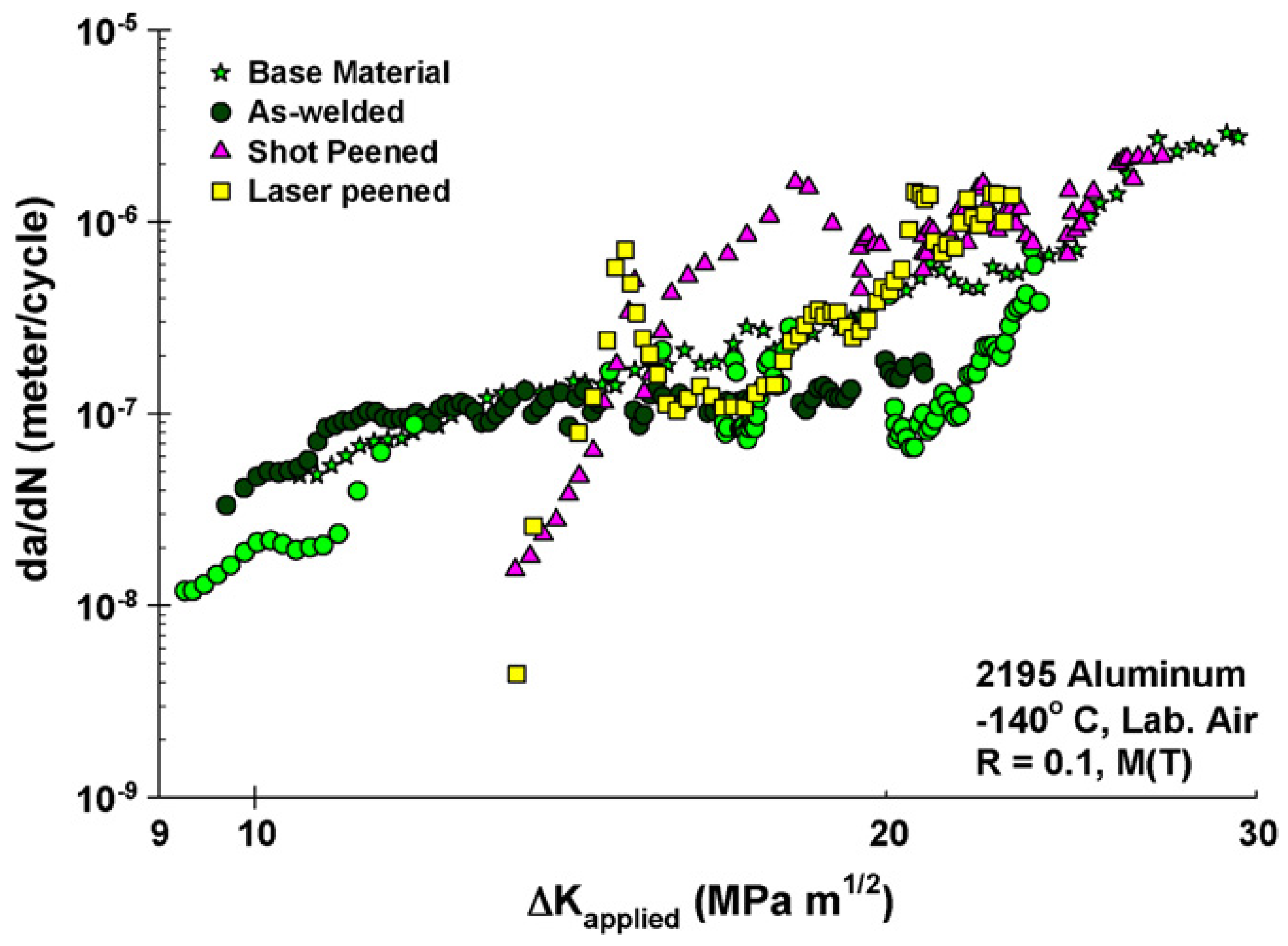
- Laser peening is recommended for the post weld treatment of friction stir welded joints. Multilayer laser peening can greatly decrease fatigue crack growth rate and improve material fatigue life. At ambient and elevated temperature, shot peening treatment has similar fatigue crack growth resistance as as-welded condition and crack growth rates were higher than the laser peened case.
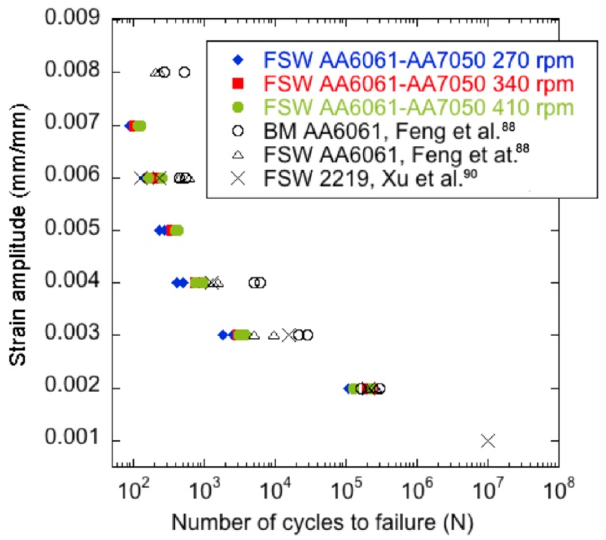
- The fatigue life data in the literature are still limited. In the high cycle stress life analysis, more testing are required for different materials at various stress amplitude and mean stress combinations. For low cycle fatigue analysis where the plastic part dominates, considerable works such as dissimilar material joint assessment are needed in the future.
Author Contributions
Funding
Conflicts of Interest
References
- Jesus, J.S.; Costa, J.M.; Loureiro, A.; Ferreira, J.M. Fatigue strength improvement of GMAW T-welds in AA 5083 by friction-stir processing. Int. J. Fatigue 2017, 97, 4–134. [Google Scholar] [CrossRef]
- Lin, P.C.; Lo, S.M.; Wu, S.P. Fatigue life estimations of alclad AA2024-T3 friction stir clinch joints. Int. J. Fatigue 2018, 107, 13–26. [Google Scholar] [CrossRef]
- Wang, Y.; Yu, L.; He, X.; Wang, C.; Yang, R.; Chen, H. Influence of current step on defect for high-speed train aluminum alloy with MIG welding. Electr. Weld. Mach. 2016, 46, 14–17. [Google Scholar]
- Sun, G.; Chen, Y.; Chen, S.; Shang, D. Fatigue modeling and life prediction for friction stir welded joint based on microstructure and mechanical characterization. Int. J. Fatigue 2017, 98, 131–141. [Google Scholar] [CrossRef]
- Ronevich, J.A.; Somerday, B.P.; Feng, Z. Hydrogen accelerated fatigue crack growth of friction stir welded X52 steel pipe. Int. J. Hydrog. Energy 2017, 42, 4259–4268. [Google Scholar] [CrossRef]
- Sharma, S.R.; Ma, Z.Y.; Mishra, R.S. Effect of friction stir processing on fatigue behavior of A356 alloy. Scr. Mater. 2004, 51, 237–241. [Google Scholar] [CrossRef]
- El-Morsy, A.W.; Ghanem, M.; Bahaitham, H. Effect of Friction Stir Welding Parameters on the Microstructure and Mechanical Properties of AA2024-T4 Aluminum Alloy. Eng. Technol. Appl. Sci. Res. 2018, 8, 2493–2498. [Google Scholar]
- Susmel, L.; Hattingh, D.G.; James, M.N.; Tovo, R. Multiaxial fatigue assessment of friction stir welded tubular joints of Al 6082-T6. Int. J. Fatigue 2017, 101, 282–296. [Google Scholar] [CrossRef] [Green Version]
- Suresh, S. Fatigue of Materials; Cambridge University Press: Cambridge, MA, USA, 1998. [Google Scholar]
- Sun, Y.; Voyiadjis, G.Z.; Hu, W.; Shen, F.; Meng, Q. Fatigue and fretting fatigue life prediction of double-lap bolted joints using continuum damage mechanics-based approach. Int. J. Damage Mech. 2017, 6, 162–188. [Google Scholar] [CrossRef]
- Shen, Z.; Ding, Y.; Chen, J.; Gerlich, A.P. Comparison of fatigue behavior in Mg/Mg similar and Mg/steel dissimilar refill friction stir spot welds. Int. J. Fatigue 2016, 92, 78–86. [Google Scholar] [CrossRef]
- Plaine, A.H.; Suhuddin, U.F.H.; Alcântara, N.G.; dos Santos, J.F. Fatigue behavior of friction spot welds in lap shear specimens of AA5754 and Ti6Al4V alloys. Int. J. Fatigue 2016, 91, 149–157. [Google Scholar] [CrossRef]
- Eslami, S.; Farahani, B.V.; Tavares, P.J.; Moreira, P.M.G.P. Fatigue behaviour evaluation of dissimilar polymer joints: Friction stir welded, single and double-rivets. Int. J. Fatigue 2018, 113, 351–358. [Google Scholar] [CrossRef]
- Cederqvist, L. Properties of friction stir welded aluminum lap joints. In Proceedings of the 2nd FSW Symposium 2000, Gothenburg, Sweden, 27–29 June 2000. [Google Scholar]
- Christner, B.; McCoury, J.; Higgins, S. Development and testing of friction stir welding (FSW) as a joining method for primary aircraft structure. In Proceedings of the 4th International Friction Stir Welding Symposium 2003, Park City, UT, USA, 14–16 May 2003. [Google Scholar]
- Fricke, W. Guideline for the Fatigue Assessment by Notch Stress Analysis for Welded Structures; International Institute of Welding: Roissy, France, 2008; Volume 13. [Google Scholar]
- Höglund, T.; Tindall, P. Designers’ Guide to Eurocode 9: Design of Aluminium Structures: EN 1999-1-1 AND-1-4; ICE Publishing: London, UK, 2012. [Google Scholar]
- Bai, L.; Wang, B. Variance analysis on axial fatigue test method for metal materials in common standards. Phys. Test. Chem. Anal. A Phys. Test. 2012, 48, 746–748. (In Chinese) [Google Scholar]
- Chen, S.; Zhu, Y.; Hu, J.; Qi, E. Research on selection method of S- N curve for hull structures. Ship Sci. Technol. 2014, 36, 22–26. (In Chinese) [Google Scholar]
- de Oliveira Miranda, A.C.; Gerlich, A.; Walbridge, S. Aluminum friction stir welds: Review of fatigue parameter data and probabilistic fracture mechanics analysis. Eng. Fract. Mech. 2015, 7, 243–260. [Google Scholar] [CrossRef]
- Rodriguez, R.I.; Jordon, J.B.; Allison, P.G.; Rushing, T.; Garcia, L. Low-cycle fatigue of dissimilar friction stir welded aluminum alloys. Mater. Sci. Eng. A 2016, 654, 236–248. [Google Scholar] [CrossRef]
- Besel, Y.; Besel, M.; Mercado, U.A.; Kakiuchi, T. Influence of local fatigue damage evolution on crack initiation behavior in a friction stir welded Al-Mg-Sc alloy. Int. J. Fatigue 2017, 99, 151–162. [Google Scholar] [CrossRef]
- He, C.; Liu, Y.; Dong, J.; Wang, Q.; Wagner, D.; Bathias, C. Fatigue crack initiation behaviors throughout friction stir welded joints in AA7075-T6 in ultrasonic fatigue. Int. J. Fatigue 2015, 81, 171–178. [Google Scholar] [CrossRef] [Green Version]
- Hrishikesh, D.A.S.; Chakraborty, D.; PAL, T.K. High-cycle fatigue behavior of friction stir butt welded 6061 aluminium alloy. Trans. Nonferrous Met. Soc. China 2014, 4, 648–656. [Google Scholar]
- Deng, C.; Gao, R.; Gong, B.; Yin, T.; Liu, Y. Correlation between micro-mechanical property and very high cycle fatigue (VHCF) crack initiation in friction stir welds of 7050 aluminum alloy. Int. J. Fatigue 2017, 104, 283–292. [Google Scholar] [CrossRef]
- Sonne, M.R.; Carlone, P.; Palazzo, G.S.; Hattel, J.H. Numerical Modeling of AA2024-T3 Friction Stir Welding Process for Residual Stress Evaluation, Including Softening Effects. Key Eng. Mater. 2014, 611–612, 1675–1682. [Google Scholar] [CrossRef]
- He, C.; Liu, Y.; Dong, J.; Wang, Q.; Wagner, D.; Bathias, C. Through thickness property variations in friction stir welded AA6061 joint fatigued in very high cycle fatigue regime. Int. J. Fatigue 2016, 82, 379–386. [Google Scholar] [CrossRef] [Green Version]
- Da Silva, J.; Costa, J.M.; Loureiro, A.; Ferreira, J.M. Fatigue behavior of AA6082-T6 MIG welded butt joints improved by friction stir processing. Mater. Des. 2013, 51, 315–322. [Google Scholar]
- Kathleen, M. ASM Handbook: Volume 12: Fractography; ASM International: Materials Park, OH, USA, 1998. [Google Scholar]
- Vidal, C.; Infante, V.; Vilaça, P. Characterisation of fatigue fracture surfaces of friction stir channelling specimens tested at different temperatures. Eng. Fail. Anal. 2015, 56, 204–215. [Google Scholar] [CrossRef]
- Edwards, P.; Ramulu, M. Fatigue performance of friction stir welded Ti–6Al–4V subjected to various post weld heat treatment temperatures. Int. J. Fatigue 2015, 75, 19–27. [Google Scholar] [CrossRef]
- Zhang, K.; Fang, Y.; Luan, G.; Zhang, J.; Hu, F. Mechanical and fatigue property of stationary shoulder friction stir welding AA6005. Trans. China Weld. Inst. 2017, 38, 25–28. (In Chinese) [Google Scholar]
- Sun, G.; Chen, Y.; Wei, X.; Shuang, D.; Chen, S. Crystal plastic modeling on fatigue properties for aluminum alloy friction stir welded joint. Mater. Sci. Eng. A 2018, 728, 165–174. [Google Scholar] [CrossRef]
- Wei, X.; Sun, G. Study on the relationship between hardness gradient and fracture location of friction stir welded joint. In Proceedings of the Beijing Mechanics Conference Annual Meeting, Beijing, China, 22 January 2018; pp. 50–51. (In Chinese). [Google Scholar]
- Effertz, P.S.; Infante, V.; Quintino, L.; Suhuddin, U.; Hanke, S.; dos Santos, J.F. Fatigue life assessment of friction spot welded 7050-T76 aluminium alloy using Weibull distribution. Int. J. Fatigue 2016, 87, 381–390. [Google Scholar] [CrossRef]
- Seighalani, K.R.; Givi, M.K.B.; Nasiri, A.M.; Bahemmat, P. Investigations on the effects of the tool material, geometry, and tilt angle on friction stir welding of pure titanium. J. Mater. Eng. Perform. 2010, 19, 955–962. [Google Scholar] [CrossRef]
- Costa, M.I.; Leitão, C.; Rodrigues, D.M. Influence of post-welding heat-treatment on the monotonic and fatigue strength of 6082-T6 friction stir lap welds. J. Mater. Process. Technol. 2017, 250, 289–296. [Google Scholar] [CrossRef]
- Shukla, S.; Komarasamy, M.; Mishra, R.S. Grain size dependence of fatigue properties of friction stir processed ultrafine-grained Al-5024 alloy. Int. J. Fatigue 2018, 109, 1–9. [Google Scholar] [CrossRef]
- Tajiri, A.; Uematsu, Y.; Kakiuchi, T.; Tozaki, Y.; Suzuki, Y.; Afrinaldi, A. Effect of friction stir processing conditions on fatigue behavior and texture development in A356-T6 cast aluminum alloy. Int. J. Fatigue 2015, 80, 192–202. [Google Scholar] [CrossRef]
- Tovo, R.; De Scisciolo, R.; Volpone, M. Proprieta’meccaniche e microstrutturali di giunti” friction stir welded” in lega d’alluminio. In Proceedings of the XXIX Convegno AIAS (AIAS 2000), Lucca, Italy, 6–8 September 2000; pp. 397–406. [Google Scholar]
- Threadgill, P.L.; Leonard, A.J.; Shercliff, H.R.; Withers, P.J. Friction stir welding of aluminium alloys. Int. Mater. Rev. 2009, 54, 49–93. [Google Scholar] [CrossRef]
- Biallas, G.; Dalle Donne, C.; Juricic, C. Monotonic and cyclic strength of friction stir welded aluminium joints. Advances in mechanical behaviour plasticity and damage. In Proceedings of the EUROMAT 2000, Munich, Germany, 27–30 September 2000; Volume 1, pp. 115–120. [Google Scholar]
- Magnusson, L.; Kallman, L. Mechanical properties of friction stir welds in thin sheet of aluminium 2024, 6013 and 7475. In Proceedings of the Second International Symposium on FSW, Gothenburg, Sweden, 27–29 June 2000. [Google Scholar]
- Kawasaki, T. Application of Friction Stir Welding to the Manufacturing of Next Generation “A-train” type Rolling Stock. In Proceedings of the 2nd International Symposium on FSW 2000, Gothenburg, Sweden, 27–29 June 2000. [Google Scholar]
- Ericsson, M.; Sandström, R. Influence of welding speed on the fatigue of friction stir welds and comparison with MIG and TIG. Int. J. Fatigue 2003, 25, 1379–1387. [Google Scholar] [CrossRef]
- James, M.N.; Bradley, G.R. Weld tool travel speed effects on fatigue life of friction stir welds in 5083 Aluminium. Int. J. Fatigue 2003, 25, 1389–1398. [Google Scholar] [CrossRef]
- Pocaterra, C.; Tovo, R. Proprieta Meccaniche di Giunti Testa a Testa FSW: Stato dell’Arte delle Leghe Leggere e Analisi Sperimentale su Leghe AA5xxx. Master’s Degree Thesis, University of Ferrara, Ferrara, Italy, 2002. [Google Scholar]
- Maddox, S.J. Review of fatigue assessment procedures for welded aluminium structures. Int. J. Fatigue 2003, 25, 1359–1378. [Google Scholar] [CrossRef]
- Carlone, P.; Citarella, R.; Sonne, M.R.; Hattel, J.H. Multiple Crack Growth Prediction in AA2024-T3 Friction Stir Welded Joints, Including Manufacturing Effects. Int. J. Fatigue 2016, 90, 69–77. [Google Scholar] [CrossRef]
- Besel, M.; Besel, Y.; Mercado, U.A.; Kakiuchi, T.; Uematsu, Y. Fatigue behavior of friction stir welded Al–Mg–Sc alloy. Int. J. Fatigue 2015, 77, 1–11. [Google Scholar] [CrossRef]
- Boni, L.; Lanciotti, A.; Polese, C. “Size effect” in the fatigue behavior of Friction Stir Welded plates. Int. J. Fatigue 2015, 80, 238–245. [Google Scholar] [CrossRef]
- Cavaliere, P.; De Santis, A.; Panella, F.; Squillace, A. Effect of anisotropy on fatigue properties of 2198 Al–Li plates joined by friction stir welding. Eng. Fail. Anal. 2009, 16, 1856–1865. [Google Scholar] [CrossRef]
- Costa, J.D.; Ferreira, J.A.M.; Borrego, L.P.; Abreu, L.P. Fatigue behaviour of AA6082 friction stir welds under variable loadings. Int. J. Fatigue 2012, 37, 8–16. [Google Scholar] [CrossRef]
- Deng, C.; Wang, H.; Gong, B.; Li, X.; Lei, Z. Effects of microstructural heterogeneity on very high cycle fatigue properties of 7050-T7451 aluminum alloy friction stir butt welds. Int. J. Fatigue 2016, 83, 100–108. [Google Scholar] [CrossRef]
- Di, S.; Yang, X.; Luan, G.; Jian, B. Comparative study on fatigue properties between AA2024-T4 friction stir welds and base materials. Mater. Sci. Eng. A 2006, 435, 389–395. [Google Scholar] [CrossRef]
- Lomolino, S.; Tovo, R.; Dos Santos, J. On the fatigue behaviour and design curves of friction stir butt-welded Al alloys. Int. J. Fatigue 2005, 27, 305–316. [Google Scholar] [CrossRef]
- Wu, Q.; Chen, X.; Fan, Z.; Niu, F.; Wei, Z. Improved formula for calculating fatigue crack growth rate and different stress ratios. J. Mech. Strength 2017, 39, 160–165. (In Chinese) [Google Scholar]
- Forman, R.G.; Kearney, V.E.; Engle, R.M. Numerical Analysis of Crack Propagation in Cyclic-Loaded Structure. Sen-ito Kogyo 1967, 49, 459–464. [Google Scholar] [CrossRef]
- Klusák, J.; Profant, T.; Knésl, Z.; Kotoul, M. The influence of discontinuity and orthotropy of fracture toughness on conditions of fracture initiation in singular stress concentrators. Eng. Fract. Mech. 2013, 110, 438–447. [Google Scholar] [CrossRef]
- Li, S. Aluminum Friction Stir Welding Head Fatigue Craek Growth Rate PILOT Study; Lanzhou University of Teehnology: Lanzhou, China, 2008. (In Chinese) [Google Scholar]
- Li, S.; Wu, L.; Liu, J.; Yu, M.; Wen, C. Effect of Load ratio and Corrosion on Fatigue Behavior of AerMet100 Ultrahigh Strength Steel. J. Aeronaut. Mater. 2014, 34, 74–80. (In Chinese) [Google Scholar]
- Czechowski, M. Low-cycle fatigue of friction stir welded Al–Mg alloys. J. Mater. Process. Technol. 2005, 164, 1001–1006. [Google Scholar] [CrossRef]
- Wang, L.; Hui, L.; Zhou, S.; Xu, L.; He, B. Effect of corrosive environment on fatigue property and crack propagation behavior of Al 2024 friction stir weld. Trans. Nonferrous Met. Soc. China 2016, 26, 2830–2837. [Google Scholar] [CrossRef]
- Meng, X.; Lin, Z.; Wang, F. Investigation on corrosion fatigue crack growth rate in 7075 aluminum alloy. Mater. Des. 2013, 51, 683–687. [Google Scholar] [CrossRef]
- Zhou, C.; Yang, X.; Luan, G. Fatigue properties of friction stir welds in Al 5083 alloy. Scr. Mater. 2005, 53, 1187–1191. [Google Scholar] [CrossRef]
- Dickerson, T.L.; Przydatek, J. Fatigue of friction stir welds in aluminium alloys that contain root flaws. Int. J. Fatigue 2003, 25, 1399–1409. [Google Scholar] [CrossRef]
- Peel, M.; Steuwer, A.; Preuss, M.; Withers, P.J. Microstructure, mechanical properties and residual stresses as a function of welding speed in aluminium AA5083 friction stir welds. Acta Mater. 2003, 51, 4791–4801. [Google Scholar] [CrossRef]
- Chi, Z.; Liu, Y.; Li, C.; Yang, X. Effects of FSW Parameters on Residual Stress and Deformation of 6082-T6 Aluminum Alloy. Hot Work. Technol. 2018, 47, 159–163. [Google Scholar]
- Zhang, Z.W.; Zhang, Z.; Zhang, H. Effect of residual stress on fatigue life of thin Al 2024 plates. Trans. China Weld. Inst. 2017, 35, 29–32. [Google Scholar]
- Huang, H.; Li, B.; Wei, S.; Wang, G. Cause analysis and elimination method of welding residual stress. Mech. Electr. Inf. 2018, 18, 115–116. (In Chinese) [Google Scholar]
- Moraes, J.F.C.; Rodriguez, R.I.; Jordon, J.B.; Su, X. Effect of overlap orientation on fatigue behavior in friction stir linear welds of magnesium alloy sheets. Int. J. Fatigue 2017, 100, 1–11. [Google Scholar] [CrossRef]
- Dialami, N.; Cervera, M.; Chiumenti, M.; Segatori, A. Prediction of joint line remnant defect in friction stir welding. Int. J. Mech. Sci. 2019, 151, 61–69. [Google Scholar] [CrossRef]
- Stevenson, R.; Toumpis, A.; Galloway, A. Defect tolerance of friction stir welds in DH36 steel. Mater. Des. 2015, 87, 701–711. [Google Scholar] [CrossRef] [Green Version]
- Rao, H.M.; Jordon, J.B.; Boorgu, S.K.; Kang, H.; Yuan, W.; Su, X. Influence of the key-hole on fatigue life in friction stir linear welded aluminum to magnesium. Int. J. Fatigue 2017, 105, 16–26. [Google Scholar] [CrossRef]
- Zhu, Y.; Chen, G.; Chen, Q.; Zhang, G.; Shi, Q. Simulation of material plastic flow driven by non-uniform friction force during friction stir welding and related defect prediction. Mater. Des. 2016, 108, 400–410. [Google Scholar] [CrossRef]
- Le Jolu, T.; Morgeneyer, T.F.; Denquin, A.; Gourgues-Lorenzon, A.F. Fatigue lifetime and tearing resistance of AA2198 Al–Cu–Li alloy friction stir welds: Effect of defects. Int. J. Fatigue 2015, 70, 463–472. [Google Scholar] [CrossRef] [Green Version]
- Zhou, C.; Yang, X.; Luan, G. Effect of root flaws on the fatigue property of friction stir welds in 2024-T3 aluminum alloys. Mater. Sci. Eng. A 2006, 418, 155–160. [Google Scholar] [CrossRef]
- Uematsu, Y.; Tokaji, K.; Shibata, H.; Tozaki, Y.; Ohmune, T. Fatigue behaviour of friction stir welds without neither welding flash nor flaw in several aluminium alloys. Int. J. Fatigue 2009, 31, 1443–1453. [Google Scholar] [CrossRef]
- Chen, H.B.; Wang, J.F.; Zhen, J.D.; Chen, S.B.; Lin, T. Effects of initial oxide on microstructural and mechanical properties of friction stir welded AA2219 alloy. Mater. Des. 2015, 86, 49–54. [Google Scholar] [CrossRef]
- He, Y.; Liu, J.; Li, Y.; Li, Y.; Chen, H. Study on Microstructure and Fatigue Properties of Double-side Friction Stir Welding Joint of A7N01S-T5 Aluminum Alloy Plates with Thickness of 42 mm. Hot Work. Technol. 2017, 46, 44–47. [Google Scholar]
- Yang, X.; Cui, L.; Xu, X.; Zhou, G. Weld Defects and Fatigue Properties of Friction Stir Overlap Joints for 6061-T6 Aluminum Alloy. J. Aeronaut. Mater. 2013, 33, 38–44. (In Chinese) [Google Scholar]
- Infante, V.; Braga, D.F.O.; Duarte, F.; Moreira, M.M.G.; Freitas, M.; de Castro, P.M.S.T. Study of the fatigue behaviour of dissimilar aluminium joints produced by friction stir welding. Int. J. Fatigue 2016, 82, 310–316. [Google Scholar] [CrossRef]
- Hatamleh, O.; Hill, M.; Forth, S.; Garcia, D. Fatigue crack growth performance of peened friction stir welded 2195 aluminum alloy joints at elevated and cryogenic temperatures. Mater. Sci. Eng. A 2009, 519, 61–69. [Google Scholar] [CrossRef]
- Jie, L. Effects of Laser Peen on 7075 Aluminum Alloy Friction Stir Welding Joints. Aerosp. Mater. Technol. 2010, 1, 16. [Google Scholar]
- Hatamleh, O.; Lyons, J.; Forman, R. Laser and shot peening effects on fatigue crack growth in friction stir welded 7075-T7351 aluminum alloy joints. Int. J. Fatigue 2007, 29, 421–434. [Google Scholar] [CrossRef]
- Moghadam, D.G.; Farhangdoost, K. Influence of welding parameters on fracture toughness and fatigue crack growth rate in friction stir welded nugget of 2024-T351 aluminum alloy joints. Trans. Nonferrous Met. Soc. China 2016, 26, 2567–2585. [Google Scholar] [CrossRef]
- Murakami, Y.; Harada, S.; Endo, T.; Tani-Ishi, H.; Fukushima, Y. Correlations among growth law of small cracks, low-cycle fatigue law and applicability of Miner’s rule. Eng. Fract. Mech. 1983, 18, 909–924. [Google Scholar] [CrossRef]
- Feng, A.H.; Chen, D.L.; Ma, Z.Y. Microstructure and low-cycle fatigue of a friction-stir-welded 6061 aluminum alloy. Metall. Mater. Trans. A 2010, 41, 2626–2641. [Google Scholar] [CrossRef]
- Feng, A.H.; Chen, D.L.; Ma, Z.Y. Microstructure and cyclic deformation behavior of a friction-stir-welded 7075 Al alloy. Metall. Mater. Trans. A 2010, 41, 957–971. [Google Scholar] [CrossRef]
- Xu, W.F.; Liu, J.H.; Chen, D.L.; Luan, G. Low-cycle fatigue of a friction stir welded 2219-T62 aluminum alloy at different welding parameters and cooling conditions. Int. J. Adv. Manuf. Technol. 2014, 74, 209–218. [Google Scholar] [CrossRef]
- Ni, D.R.; Chen, D.L.; Yang, J.; Ma, Z.Y. Low cycle fatigue properties of friction stir welded joints of a semi-solid processed AZ91D magnesium alloy. Mater. Des. (1980–2015) 2014, 56, 1–8. [Google Scholar] [CrossRef]
- Rambabu, G.; Naik, D.B.; Rao, C.H.V.; Rao, K.S.; Reddy, G.M. Optimization of friction stir welding parameters for improved corrosion resistance of AA2219 aluminum alloy joints. Def. Technol. 2015, 11, 330–337. [Google Scholar] [CrossRef]
- Elatharasan, G.; Kumar, V.S.S. Modelling and Optimization of Friction Stir Welding Parameters for Dissimilar Aluminium Alloys Using RSM. Procedia Eng. 2012, 38, 3477–3481. [Google Scholar] [CrossRef]
- De Filippis, L.A.C.; Serio, L.M.; Palumbo, D.; De Finis, R.; Galietti, U. Optimization and Characterization of the Friction Stir Welded Sheets of AA 5754-H111: Monitoring of the Quality of Joints with Thermographic Techniques. Materials 2017, 10, 1165. [Google Scholar] [CrossRef] [PubMed]
- Ugrasen, G.; Bharath, G.; Kumar, G.K.; Sagar, R.; Shivu, P.R.; Keshavamurthy, R. Optimization of Process Parameters for Al6061-Al7075 alloys in Friction Stir Welding using Taguchi’s Technique. Mater. Today Proc. 2018, 5, 3027–3035. [Google Scholar] [CrossRef]
- Wakchaure, K.N.; Thakur, A.G.; Gadakh, V.; Kumar, A. Multi-Objective Optimization of Friction Stir Welding of Aluminium Alloy 6082-T6 Using hybrid Taguchi-Grey Relation Analysis—ANN Method. Mater. Today Proc. 2018, 5, 7150–7159. [Google Scholar] [CrossRef]
- Han, L.; Blundell, N.; Lu, Z.; Shergold, M.; Chrisanthou, A. Fatigue Behaviour of Friction Stir Joined Aluminium Alloy NG5754 and AA6111; SAE Technical Papers 2007-01-1704; SAE International: Warrendale, PA, USA, 2007. [Google Scholar]
- Vadher, T.; Parmar, G.S. Fatigue behaviour of aluminium alloy plates joined by friction stir welding. Int. J. Technol. Res. Eng. 2017, 4, 984–987. [Google Scholar]
- Garware, M.; Kridli, G.T.; Mallick, P.K. Tensile and Fatigue Behavior of Friction-Stir Welded Tailor-Welded Blank of Aluminum Alloy 5754. J. Mater. Eng. Perform. 2010, 19, 1161–1171. [Google Scholar] [CrossRef]
- Lukács, J.; Meilinger, Á.; Pósalaky, D. High cycle fatigue and fatigue crack propagation design curves for 5754-H22 and 6082-T6 aluminium alloys and their friction stir welded joints. Weld. World 2018, 62, 737–749. [Google Scholar] [CrossRef]
- Enke, N.F.; Sandor, B.I. Cyclic plasticity analysis by differential infrared thermography. In Proceedings of the VI International Congress on Experimental Mechanics, Portland, OR, UAS, 6–10 June 1988; pp. 830–835. [Google Scholar]
- Shiozawa, D.; Inagawa, T.; Washio, T.; Sakagami, T. Fatigue limit estimation of stainless steels with new dissipated energy data analysis. Procedia Struct. Integr. 2016, 2, 2091–2096. [Google Scholar] [CrossRef]
- De Finis, R.; Palumbo, D.; Da Silva, M.M.; Galietti, U. Is the temperature plateau of a self-heating test a robust parameter to investigate the fatigue limit of steels with thermography? Fatigue Fract. Eng. Mater. Struct. 2018, 41, 917–934. [Google Scholar] [CrossRef]
- Munier, R.; Doudard, C.; Calloch, S.; Weber, B. Determination of high cycle fatigue properties of a wide range of steel sheet grades from self-heating measurements. Int. J. Fatigue 2014, 63, 46–61. [Google Scholar] [CrossRef]
- Palumbo, D.; De Finis, R.; Serio, L.M.; Galietti, U.; De Filippis, L.A.C. Thermographic signal analysis of friction stir welded AA 5754 H111 joints. Proc. SPIE Int. Soc. Opt. Eng. 2018, 10661, 106610Y. [Google Scholar]


| Material | Rotating Speed (rpm) | Welding Speed (mm/min) | Thickness (mm) | Stress Ratio, R | Ref. | |
|---|---|---|---|---|---|---|
| A356-T6 | 500/1000 | 150 | 5 | −1 | 155/130 | Tajiri et al. [39] |
| AA5083-H321 | - | - | 6 | 0.1 | 82.5 | Tovo et al. [40] |
| 5083-O | - | - | 6 | 0.1 | 102 | Threadgill et al. [41] |
| 2024-T3 | 2400 | 240 | 1.6 | 0.1 | 159.2 | Biallas et al. [42] |
| 2014A-T6 | - | - | 6 | 0.1 | 47.77 | Threadgill et al. [41] |
| 6013-T6 | 2000 | 208 | 1.6 | 0.1 | 111.88 | Magnusson and Kallman. [43] |
| A6N01-T5 | 12 | 0.1 | 91.18 | Kawasaki. [44] | ||
| 7475-T76 | 950 | 110 | 2 | 0.1 | 115.58 | Magnusson and Kallman. [43] |
| AA6082-T6 | 2500 | 1400 | 4 | 0.5 | 51.51 | Ericsson and Sandstro [45] |
| 5083-H321 | 500 | 80 | 8 | −1 | 144.92 | James and Bradley [46] |
| AA5083-H3214 | - | 450 | 5 | 0.1 | 94.34 | Pocaterra and Tovo [47] |
| ALUSTAR-H321 | - | 350 | 5 | 0.1 | 70.08 | |
| AA6082-T5 | - | - | 5 | 0.5 | 53.02 | Maddox [48] |
| 6005A | 2100 | 1000 | 4.5 | 1 | 105 | Zhang et al. [32] |
| 5024-H116 | 1200 | 720 | 3.3 | −1 | 180 | Besel et al. [50] |
| AA2195-T8 | 800 | 54 | 5 | 0.1 | 185 | Boni et al. [51] |
| AA2198-T851 | 1000 | 80 | 4 | 0.33 | 178 | Cavaliere et al. [52] |
| AA6082-T6 | 1500 | 300 | 4 | −1 | 170 | Costa et al. [53] |
| 6061 | 1000 | 80 | 2 | 0.3 | 38 | Hrishikesh et al. [24] |
| 7050-T7451 | 800 | 150 | 12 | −1 | 202 | Deng et al. [54] |
| 2024-T4 | 800–1000 | 150–250 | 4 | 0.1 | 73.71 | Di et al. [55] |
| Specimen | Rotation-Welding Speed (rpm–mm/min) | Fatigue Strength Coefficient, σf (MPa) | Fatigue Strength Exponent, b | Fatigue Ductility Coefficient, εf | Fatigue Ductility Exponent, c | Ref. |
|---|---|---|---|---|---|---|
| 6061Al-T651 | Base Metal | 760 | −0.12 | 0.22 | −0.72 | Feng et al. [88] |
| 1400–600 | 509 | −0.09 | 0.29 | −0.71 | ||
| 1400–400 | 476 | −0.09 | 0.34 | −0.73 | ||
| 1400–200 | 436 | −0.08 | 0.56 | −0.79 | ||
| 1000–200 | 419 | −0.08 | 0.24 | −0.69 | ||
| 600–200 | 404 | −0.08 | 0.41 | −0.75 | ||
| 2219-T62 A: Air cooling W: Water cooling | Base Metal | 751 | −0.10 | 0.04 | −0.50 | Xu et al. [90] |
| 300-100-A | 517 | −0.09 | 0.64 | −0.79 | ||
| 1000-100-A | 555 | −0.1 | 0.75 | -0.84 | ||
| 1000-100-W | 575 | −0.11 | 0.59 | −0.80 | ||
| 750-60-A | 353 | −0.05 | 0.04 | −0.49 | ||
| 750-200-A | 448 | −0.08 | 0.05 | −0.60 | ||
| Thixomolded AZ91D alloy | Base Metal | 494 | −0.12 | 0.034 | −0.39 | Ni et al. [91] |
| 800-50 | 549 | −0.16 | 0.081 | −0.58 | ||
| Dissimilar FSW of AA6061-to-AA7050 | 270-114 | 196.7 | −0.03 | 0.16 | −0.75 | Rodriguez et al. [21] |
| 360-114 | 218.3 | −0.04 | 0.0.13 | −0.69 | ||
| 410-114 | 238.7 | −0.04 | 0.14 | −0.68 |
| Total Strain Amplitude (%) | Total Energy (MJ/m3) | Average Energy per Cycle (MJ/m3) | Total Number of Cycles to Failure (Nf) |
|---|---|---|---|
| 0.6 | 299.0 | 0.20 | 1736 |
| 0.6 | 338.8 | 0.27 | 1406 |
| 0.8 | 735.5 | 2.45 | 478 |
| 0.8 | 600.9 | 2.18 | 469 |
| 1.0 | 504.4 | 5.80 | 173 |
| 1.0 | 420.8 | 5.19 | 107 |
© 2018 by the authors. Licensee MDPI, Basel, Switzerland. This article is an open access article distributed under the terms and conditions of the Creative Commons Attribution (CC BY) license (http://creativecommons.org/licenses/by/4.0/).
Share and Cite
Li, H.; Gao, J.; Li, Q. Fatigue of Friction Stir Welded Aluminum Alloy Joints: A Review. Appl. Sci. 2018, 8, 2626. https://doi.org/10.3390/app8122626
Li H, Gao J, Li Q. Fatigue of Friction Stir Welded Aluminum Alloy Joints: A Review. Applied Sciences. 2018; 8(12):2626. https://doi.org/10.3390/app8122626
Chicago/Turabian StyleLi, Hongjun, Jian Gao, and Qinchuan Li. 2018. "Fatigue of Friction Stir Welded Aluminum Alloy Joints: A Review" Applied Sciences 8, no. 12: 2626. https://doi.org/10.3390/app8122626
APA StyleLi, H., Gao, J., & Li, Q. (2018). Fatigue of Friction Stir Welded Aluminum Alloy Joints: A Review. Applied Sciences, 8(12), 2626. https://doi.org/10.3390/app8122626