Review

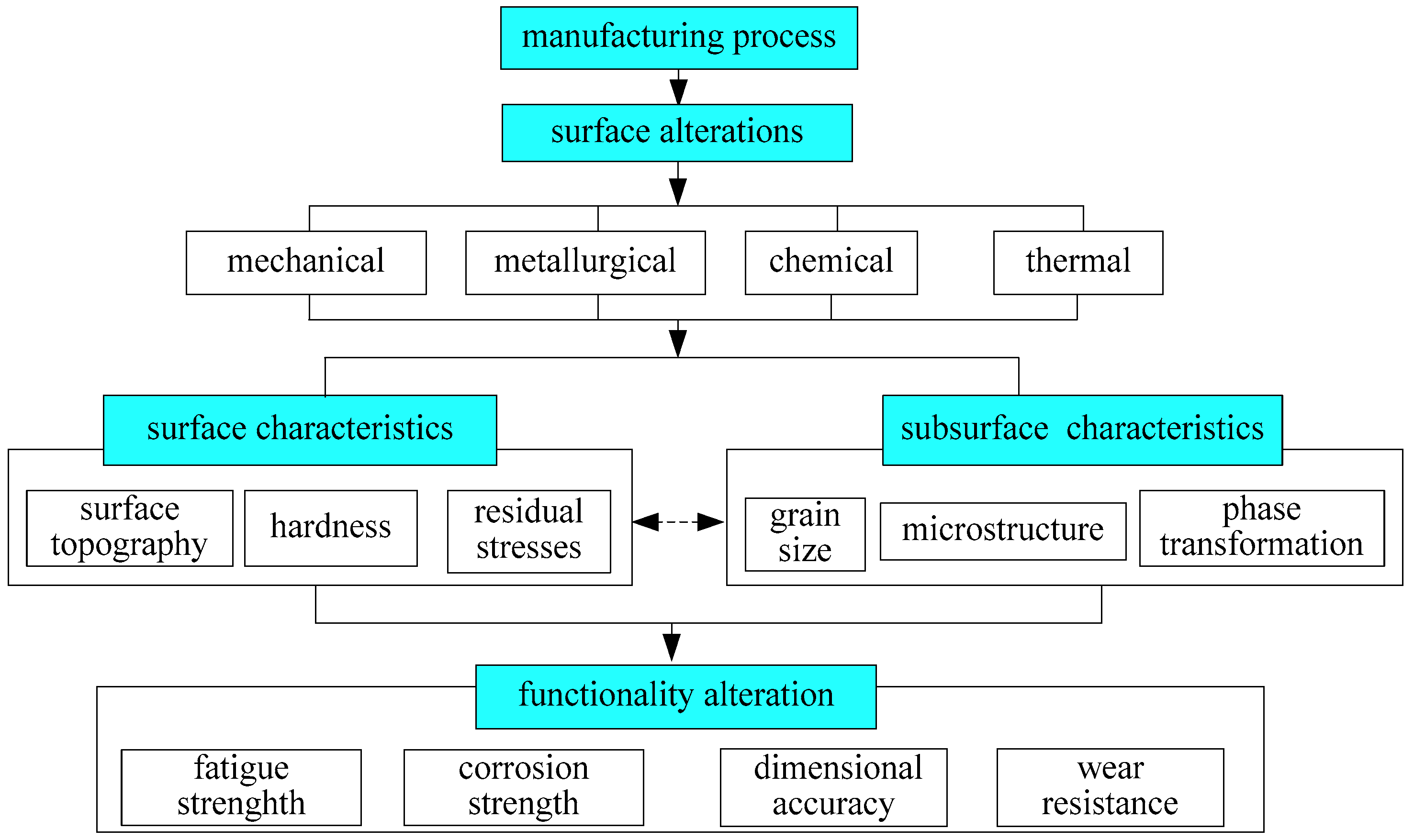
Part Functionality Alterations Induced by Changes of Surface Integrity in Metal Milling Process: A Review

1
Harbin University of Science and Technology, Harbin 150080, China
2
Georgia Institute of Technology, Atlanta, GA 30332-0405, USA
*
Author to whom correspondence should be addressed.
Appl. Sci. 2018, 8(12), 2550; https://doi.org/10.3390/app8122550
Submission received: 19 September 2018 / Revised: 4 November 2018 / Accepted: 14 November 2018 / Published: 9 December 2018

Abstract

:
It has been proved that surface integrity alteration induced by machining process has a profound influence on the performance of a component. As a widely used processing technology, milling technology can process parts of different quality grades according to the processing conditions. The different cutting conditions will directly affect the surface state of the machined parts (surface texture, surface morphology, surface residual stress, etc.) and affect the final performance of the workpiece. Therefore, it is of great significance to reveal the mapping relationship between working conditions, surface integrity, and parts performance in milling process for the rational selection of cutting conditions. The effects of cutting parameters such as cutting speed, feed speed, cutting depth, and tool wear on the machined surface integrity during milling are emphatically reviewed. At the same time, the relationship between the machined surface integrity and the performance of parts is also revealed. Furthermore, problems that exist in the study of surface integrity and workpiece performance in milling process are pointed out and we also suggest that more research should be conducted in this area in future.

1. Introduction

In today’s competitive manufacturing industry, the ultimate goal of manufacturers is to produce higher-performance products at lower cost and in less time. At the end of the machining process chain, thermomechanical coupling load has significant impact on workpiece surface property with a direct link to functionality. To get a reliable machined component with high fatigue strength, high wear resistance, and high dimensional accuracy are the goals of the machining process. It is necessary to evaluate the effects of machining parameters, tool parameters, etc. on machined surface performance capabilities.
The specified term surface integrity can be used to evaluate the machined surface properties after manufacturing operations. There are mainly some aspects to describe surface integrity: topography, metallurgy characteristics and residual stress. The topography is made up of surface roughness, waviness and flaws. The metallurgy characteristics include grain size, plastic deformation, microhardness, phase transformation, recrystallization, etc. [1].
The door to the study of machined surface integrity is opened by a review article written by Field et al. [2]. The results show that surface integrity is the intrinsic property of surface hardening conditions that are produced after processing [3]. Then, considerable research on machined surface integrity was carried out [4,5,6,7,8]. The CIRP (The International Academy for Production Engineering) published its keynote paper “Capability Profile of Hard Cutting and Grinding Processes” in 2005 to guide the research of surface integrity; subsequently, a collaborative working group on surface integrity and functional performance of components was established in 2008 [9].
The ultimate research goal of surface integrity is to get the component with high performance capacity. In the cutting process, the finishing pass will define the thermos and mechanical state of the machined surface. Surface integrity has a significant impact on several relevant characteristics of the final functionality of the component, such as dimensional accuracy, friction coefficient, wear and thermal resistance, and fatigue behavior corrosion, as shown in Figure 1. For example, the finished component may lose efficacy for many reasons, such as changes in dimensions due to wear or plastic deformation, deterioration of the surface finish, and cracking or breakage [10]. Therefore, it is important to reveal the effect of the manufacturing process on finish part functionality.
The definition of surface function differs depending on the operating performance of the surface. For example, when translational surfaces are used as surfaces for the bearing inner and outer rings, tribological functionality will become dominant. However, for the applications of dynamic loading and cyclical stresses, fatigue characteristics may be a prime consideration in determining component failure [11]. Therefore, in order to get the influence mechanism of cutting parameters on parts performance, it is important to study the intrinsic relationship between the factors of surface integrity and parts performance [6].
Milling has the advantages of high production efficiency and wide processing range, and it is widely used in key fields such as aerospace, mold, automobile, and parts manufacturing [12]. To reveal the topic more clearly, the surface integrity and functionality of the part after the milling process are focused on in this paper. The effects of the manufacture process on surface integrity are discussed. Through the analysis research and the finite element modeling method, the surface integrity can be better understood. Then, a review of the state-of-art research on finished component functionality affected by surface integrity, such as surface topography, surface metallography, and residual stress, is presented. In this review, the component functionality mainly includes fatigue strength and wear resistance.

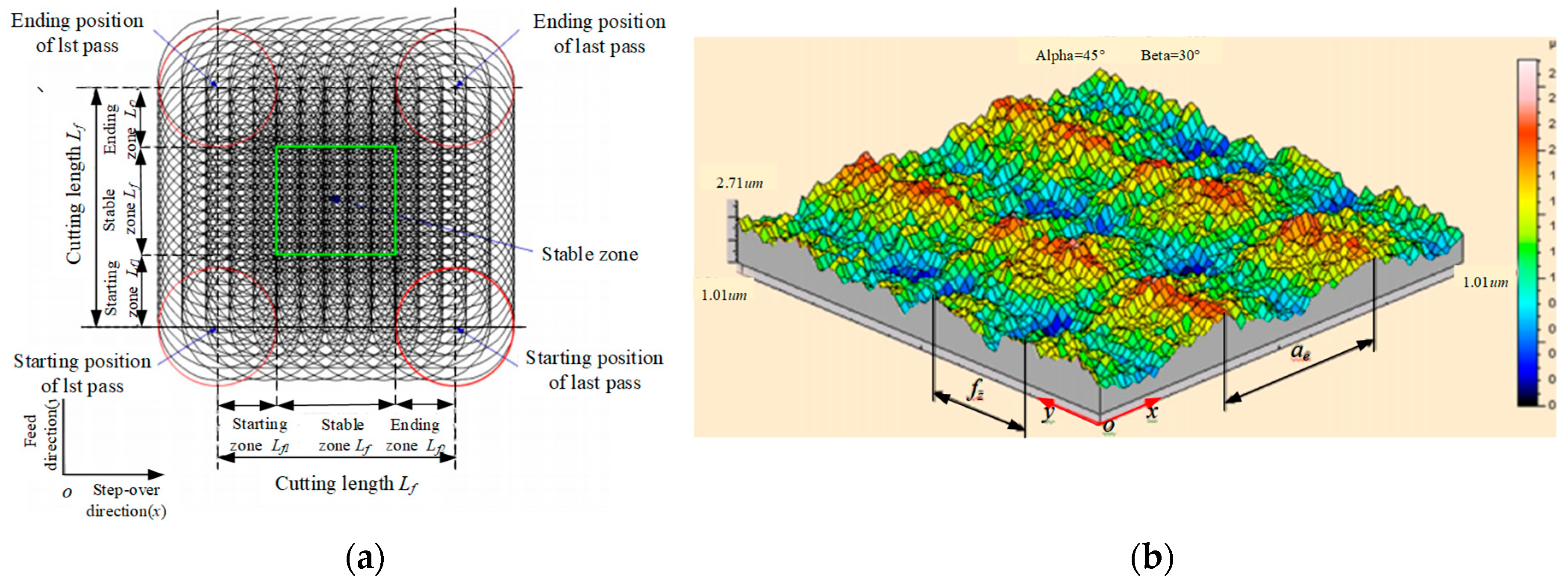
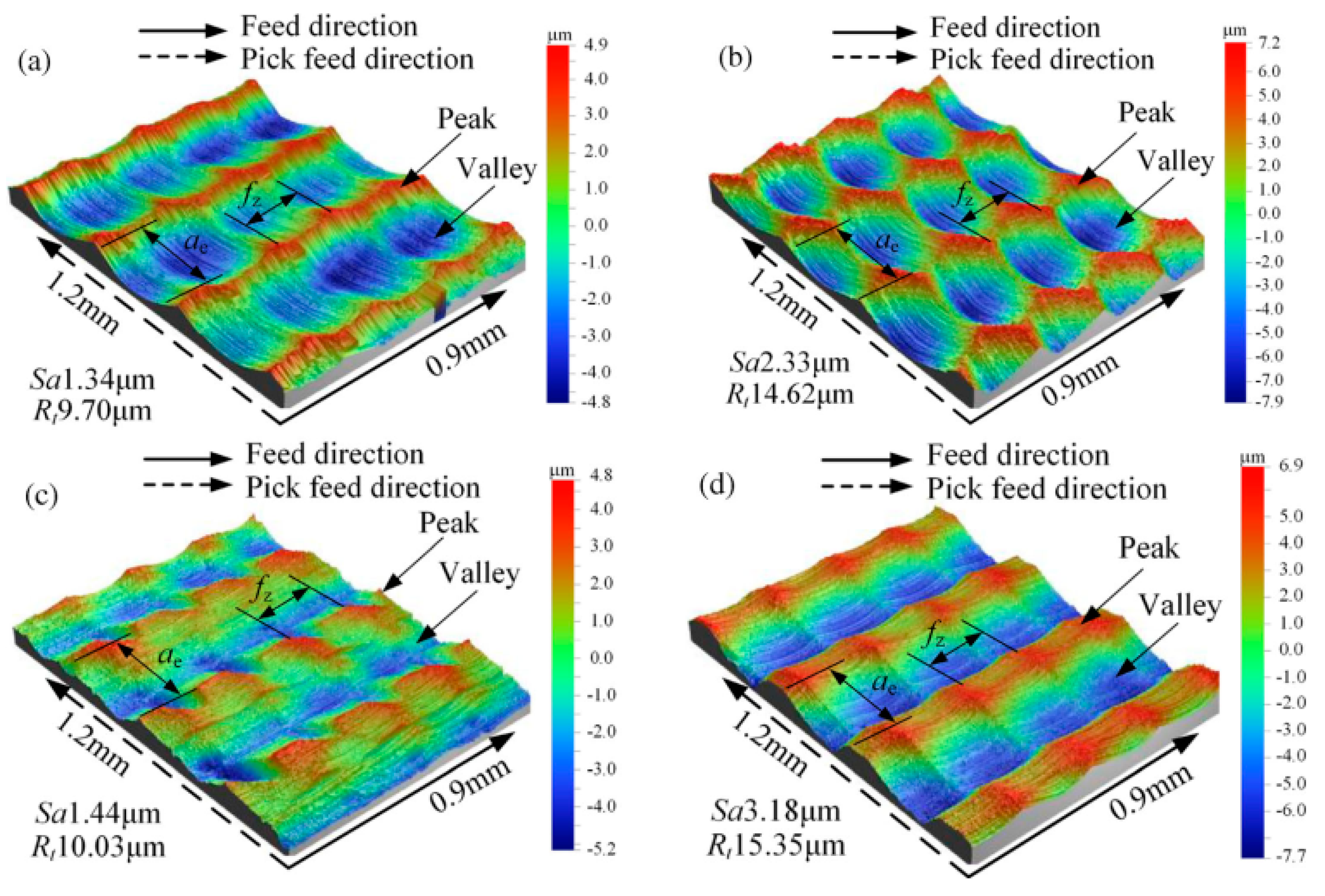
2. Part Functionality as Effected by Surface Topography

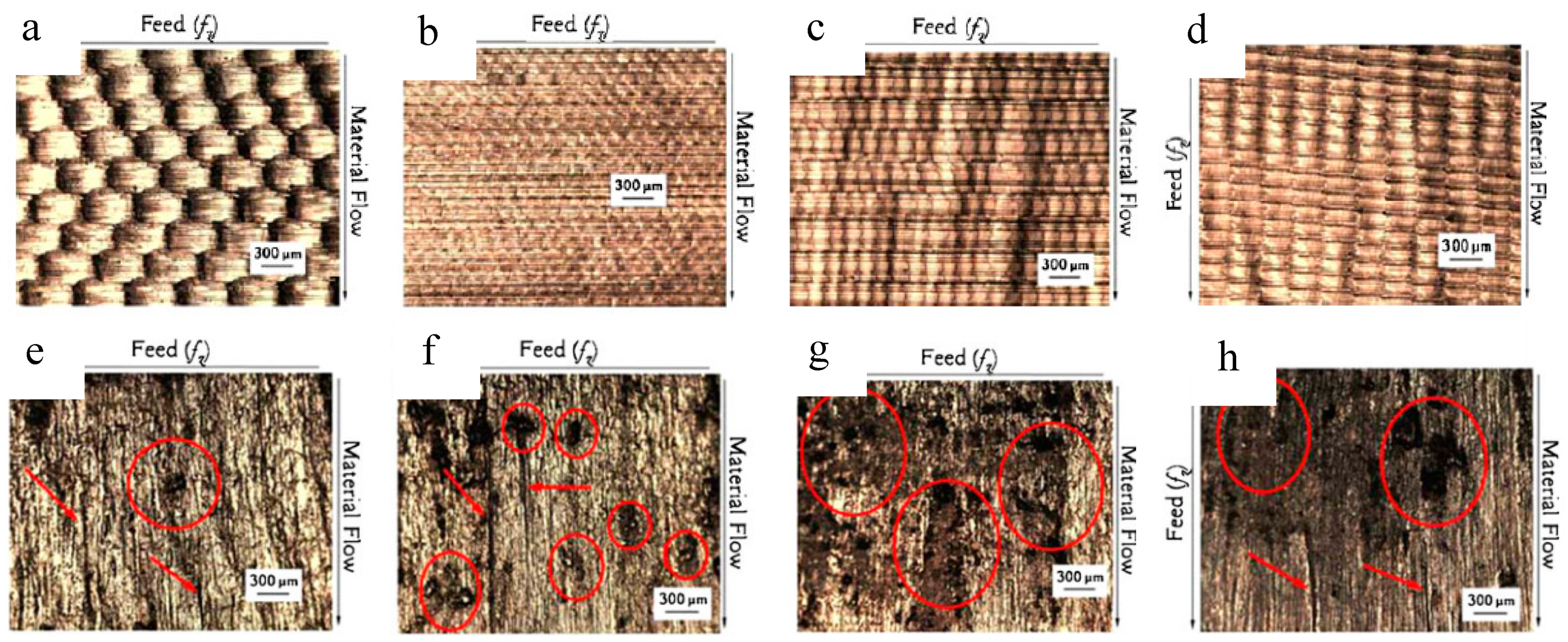
2.1. Machined Surface Topography Characteristic

The surface topography of any manufacturing process is a critical index. It is mainly affected by geometric properties of the machining system for milling process. Choosing suitable cutting parameters for given tools, workpiece materials, and machine tools is an important step to get reasonable surface topography. Because the two-dimensional parameters cannot properly represent the surface features of milling, more and more attention is being paid to three-dimensional parameters today.
Considerable research has been performed to get suitable surface topography. Zhang et al. [13] provided in-depth characterization and analysis of the three-dimensional topography of feed direction and cross-feed direction in the hard milling process of AISI H13 steel (AISI is an abbreviation of American Iron and Steel Institute), as shown in the Figure 2. The results show that better surface morphology can be obtained by using higher cutting speed, lower feed speed, and lower cutting depth. Wang et al. [14] studied the surface morphology and surface roughness in the milling process of AlMn1Cu. Due to the high ductility of the AlMn1Cu material, the material flows plastically along the side-cutting edge and meanwhile is extruded by the side-cutting edge to cause the material to accumulate on the machined surface. With the increase of cutting depth and feed per tooth, the plastic flow of the material along the cutting edge is strengthened, resulting in increased surface roughness. However, with the increase of cutting speed, the plastic flow of the material is weakened along the secondary cutting edge, resulting in that the surface roughness value decreases. Ghani et al. [15] found that high cutting speed, low feed rate, and low cutting depth can be used to obtain ideal surface quality in the semifinishing and finishing process of AISI H13 steel.
Some scholars carried out the research of prediction of surface topography for milling process. As established by experimental tests, the actual roughness values obtained usually deviates from theoretical ones. There are several reasons accounting for this, such as runout of the milling cutter tooth tips, rounding of the cutting edge, and irregularities of cutting edge [16].
In order to design a machining process for blades in turbine engines without prior experiment, Denkena et al. [17] developed a model to predict the surface topography. The effect of stochastic topography on the flow losses was investigated also in his research. The machined surface was studied by combining the dynamic morphology with the random topography based on empirical data. The results show that the random morphology has a great influence on the flow loss and therefore cannot be ignored. Zhang et al. [18] proposed a milling topography simulation model considering tool wear. The experimental results of cutting under plane and cylindrical surfaces are in good agreement with the model prediction, which proves the correctness of the model. Irene et al. [19] established a numerical model to predict the surface topography of milling process based on the contact relationship between tool and workpiece.
Gao et al. presented an analytical model that considered the effects of tool geometry, cutting conditions, and plastic flow measurements to predict surface topography [20]. Arizmendi et al. established a surface topography prediction model considering tool vibration [21]. Lazoglu et al. [22] established an analysis model for the surface topography of five-axis milling process considering cutting parameters, number of cutting edges, and cutter runout.
The cutting trajectory is another factor that should not be neglected in the prediction model of surface topography. Based on the tool machining paths and the trajectory equation of the cutting edge relative to the workpiece, Zhang et al. [23] developed an iterative algorithm for numerical simulation of machining surface topography in multiaxis milling. Gao et al. [24] proposed a new method to predict the machined surface topography with relative cutting edge trajectory equation. Tan et al. explored the effects of different tool paths on the surface morphology, and the results are shown in Figure 3. By comparing Sa and Rt values, it found that vertical upward is the optimal cutting path [25]. Chen et al. [26] studied the effect of different angle combinations on the surface topography in multiaxis milling. Better surface roughness could be achieved when rotation angles are 0 (positive lead), 60 (combination of positive tilt and positive lead), 90 (positive tilt), and 330 (combination of negative tilt and positive lead). Lu et al. [27] studied the micrometer milling mechanism of Inconel 718 and concluded that the status of the machined surface is determined by the profile of the cutter, the cutting path of the cutter and the flexible deformation of the cutter. Therefore, the author comprehensively considered these three factors to build three-dimensional surface topography and a surface roughness prediction model. Compared with the experimental results, the maximum relative error of the model is 10.9% and the average relative error is 6.8%. The results can be used as a reference for the prediction of surface milling.
By combining boundary intersection and mean squared error method, Brito developed the prediction on surface roughness in AISI 1045 steel end milling process. The results showed that the achieved optimum lessens the sensitivity to the variability transmitted [28]. Tangjitsitcharoen et al. used the dynamic milling force ratio to predict the surface roughness of the ball milling process. The model was verified by experiments. The results show that the model can predict the average surface roughness accuracy up to 92.82% [29]. Also, some other research works were developed to get reasonable surface texture [30,31]. Toh et al. analyzed the surface texture generation mechanism under different tool paths by using the method of surface topography analysis, and obtained the best surface texture when the workpiece was inclined at 75° for high speed milling and then determined the optimized machining path [32].
Meanwhile, there may be defect appearing on the machined surface in milling process. Common surface defects are feed mark, tearing surface, and burr formation. Feed marks are produced by the combined effect of tool rotation caused by cutting speed and tool movement caused by feed speed [33]. Feed marks on machined surfaces become more pronounced with increasing cutting speeds and tool wear [34]. Tearing surfaces usually include smeared material, surface microvoids, scratches, and groove and pitting corrosion. The typical tearing surfaces is showed in Figure 4. Damage on the machined surface in hard milling process of FGH95 PM superalloy was investigated by Du and Liu [35]. Their research results showed that several defects appeared on the machined surface at higher cutting speeds. The results are significant for the prediction of component service life.
When the tool moves along the feed direction, the workpiece material will flow laterally under the combined extrusion action of the minor flank face and the machined surface causing smearing. The surface microvoids are formed from the carbide particles of the workpiece material, the cutting off of the cutting tools, and the deposition of the chip. The surface microvoids affect the mechanical properties of the workpiece, so the surface microvoids should be avoided in the key components [36].
Also, burr defects are often observed in the area where the tool exits the cutting zone, and the formation of burr is easy to cause stress concentration and reduce the fatigue life of the components. Generally, the materials with low thermal conductivity and Young’s modulus are more likely to form burrs on the cutting surface [37]. Under normal circumstances, the burr decreases with the increase of cutting speed, and increases with the increase of tool wear [34].
Generally, cutting parameters with high cutting speed, low feed rate, and low cutting depth is recommend for a good surface finish for milling process.

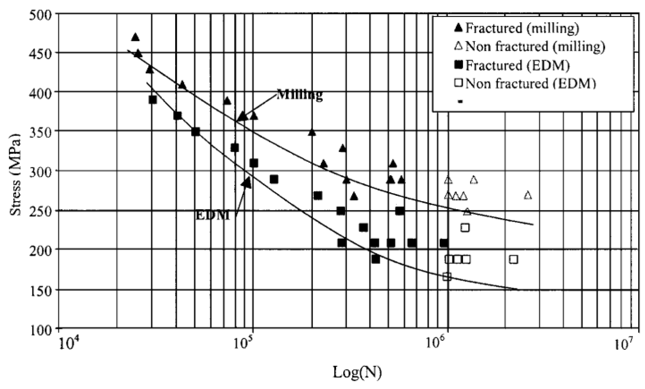
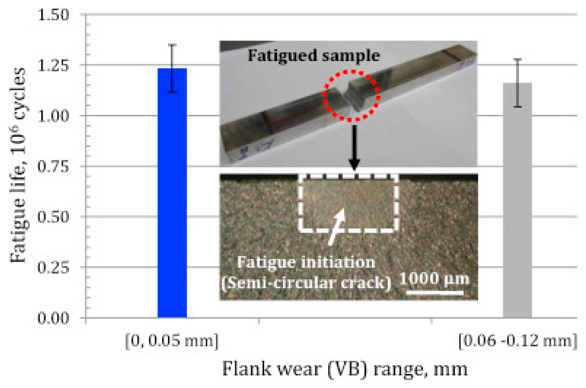
2.2. Fatigue Strength and Wear Resistance as Effected by Surface Topography

Milling process is generally applied to conduct finishing machining of sculptured surfaces, therefore the machined component have very demanding specifications in surface topography for its performance. The smoothest surfaces are desired in most milling processes, especially when the fatigue life of the part being machined is high [38]. However, in some biomedical fields, it is desirable to have rough surface morphology [39]. The surface structure is responsible for the mechanical functionality of the component. Sometimes, even if the surface dimension and surface finish of a component are well within the tolerance, there remains the possibility of lack of surface quality for a milled surface. The reason is surface topography influences not only the mechanical and physical properties of contacting parts, but also optical and coating properties of some no contacting components.
Because of the stress concentration caused by pits and groove, the characteristics of milling morphology have important influence on its performance. Generally, rougher surfaces are expected to encourage fatigue crack initiation. It is suggested that parameters such as Rt and Rz are more appropriate than Ra in respect of fatigue strength, as they equate with adverse component surface features [38]. Arola et al. [40] used surface roughness to estimate the effective stress concentration coefficient of high strength low alloy steel workpiece. It was found that the fatigue strength decreased with the increase of surface roughness at low stress level. Moussaoui et al. studied the factors that affect the fatigue life of titanium alloys. They found that the surface roughness does not affect the fatigue life of the workpiece [41]. Guo et al. found that the surface roughness has a slightly influence on four-point bending fatigue life for end milling process of AISI H13 [42]. Li et al. [43] found that surface roughness has little influence on fatigue life due to the small ratio between the ten-point surface height and the bottom curvature radius of surface gaps. Wang et al. [44] found that high surface roughness leads to a high stress concentration coefficient, which reduces the fatigue life of the workpiece.
The machined surface morphology affects the fatigue performance of the final assembly, especially when the crack initiation life is noteworthy [45,46]. Therefore, many works have been done to explore the effect of surface topography on part performance. The traditional two-dimensional surface roughness does not adequately characterize the effect of surface properties on the fatigue performance, while the three-dimensional topography can provide a more accurate correlation with fatigue behavior [47,48,49].
Performance and reliability of engineering components can be enhanced by selecting appropriate 3D topographic characteristics [50]. Novovicetc et al. investigated the effected of surface and subsurface condition on the fatigue life of Ti alloy workpiece. Their research results indicated that the surface topography, in particular texture direction, showed a strong correlation with the fatigue life of workpiece [51]. Piska et al. [52] studied the effect of progressive milling process on the surface morphology and fatigue properties of 7475-T7351 high-strength aluminum alloy. The results show that the surface topography is not the right factor affecting the fatigue properties of aluminum alloys.
When the roughness level is the same, the milling surface has a higher fatigue limit than the grinding surface. The reason is that the surface grooves produced by milling process are more random [53]. Huang et al. [54] studied the effect of different tool paths on the fatigue life of AISI H13 high speed milling process. It was noted that different tool paths lead to the difference of microscopic stress concentration caused by the orientation morphology, which affects the fatigue performance of the workpiece.
The surface integrity after machining directly affects the life and reliability of the workpiece, so it is important to study the effect of different surface integrity on the friction and wear properties of the workpiece surface to improve the service life of the workpiece. Sedlaek et al. [55] studied the relationship between surface roughness parameters and friction and wear properties of mold surface. The results show that the friction coefficient is inversely proportional to the surface roughness under the condition of dry friction, and the change trend is opposite in the lubrication conditions. Menezes et al. [56] studied the effect of surface texture on friction coefficient and adhesion wear in friction pair. The results show that the friction coefficient and adhesion wear are mainly influenced by the surface texture, which is independent of the surface roughness. Magri et al. [57] studied the relationship between surface morphology and wear resistance during die milling. They found that the best tribological performance was that composed of microcavities generated by similar and high values of fz and ae. The surface topography under four cutting conditions and the die wear results is shown in Figure 5.
After milling processes, surface topography has a direct impact on part functional performance, especially in respect of fatigue life and wear resistance. The reason is the surface topography has close relationship with surface frictional characteristic and stress distribution of milled surface. To get a good performance part, the surface topography should be selected according to the application condition of workpiece.

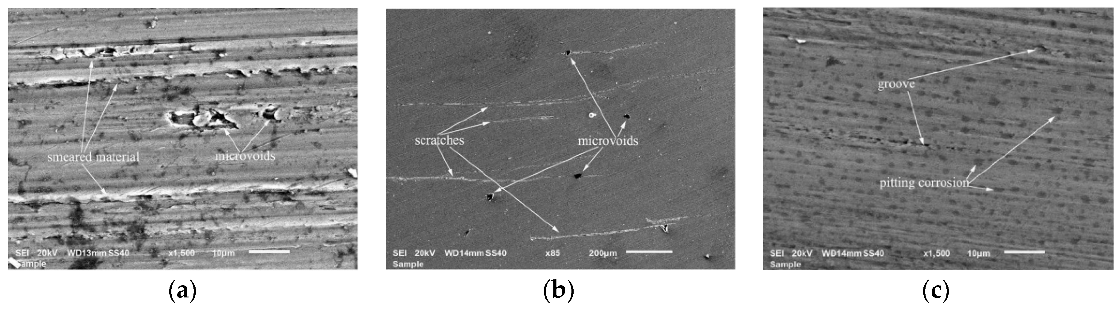
3. Part Functionality as Effected by Surface Metallurgy

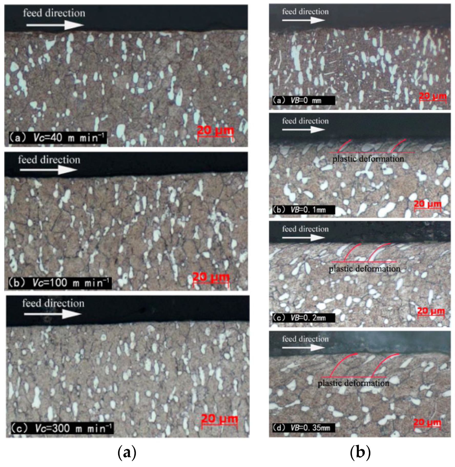
3.1. Machined Surface Metallurgy Characteristic

In milling of high hardness material or difficult–to-machine metal material, high stress, strain rate, and temperature will have a severe impact on the machined surface. The microscale and nanometer scale existing on the machined surface will change under the interaction of large strain, high strain rate and high temperature [58,59]. The property changes include microstructure change, plastic deformation. Many research works have been done on process mechanics and surface integrity due to the complex coupling between phase transformations and loading in milling process [60]. Generally, the depth of microstructural alteration has been observed to increase when the cutting speed, feed rate and tool wear are increased.
For milling process, Elbestawi et al. investigated the microstructural alterations in high speed milling of hardened AISI H13 using PCBN (Polycrystalline Cubic Boron Nitride) ball-nose end tools. They found that the formation of phase transformation layer was dependent on tool edge preparation and tool wear [61].
Both thermal and mechanical effects attribute to the plastic deformations significantly. Mechanical effects play a major role in the hardening of materials, while thermal effects play a major role in the softening of materials. Moreover, the rubbing effect of flank face on machined surface play an important role in its generation. That is why the tool wear increases from initial condition to its life value, the changed microstructure turns to be deeper. The effects of cutting speed and tool wear on the surface microstructure were investigated when milling titanium alloy Ti-1023 [34]. When VB = 0 (Tool wear value), the cutting speed has no effect on the phase transition or deformation of the machined surface, as shown in Figure 6a. Tool Wear has a significant effect on the plastic deformation and the depth of microstructure of the machined surface, as shown in Figure 6b.
The reasonable selection of cutting parameters in the finishing process does not cause the change of the structure type of the machined surface. The reason is the contact area between the cutting tool and the machined surface is so smaller that the maximal temperature of the machined surface would be lower than the austenitizing temperature of workpiece material [62]. The similar results were found by Li and Zhao [63] and Devillez et al. [64].
Extensive experimental work has been conducted to get an ideal surface metallurgical for machining process. However, indispensable hardware is needed for this method. So the modeling for machined surface microstructure has attracted wide attention [65,66,67,68,69]. Unfortunately, few research works focused on the milling process are found.
After high-speed milling of Ti-6Al-4V and Ti-834, the microstructural subsurface damage in the form of intense slip bands was identified by Thomas et al. Due to a reduction in fatigue crack initiation resistance, the microstructural subsurface damage could degrade the in-service properties of workpiece [70]. Shyha et al. [71] studied the influence law of cutting fluid supply system on metallurgical characteristics, and concluded that cutting fluid had little influence on the microstructure and deformation layer of cutting subsurface; cutting speed was a key factor affecting microstructure. Li et al. [72] carried out an experimental study on hard milling of AISI H13 steel, and the results showed that the nanohardness and plastic deformation depth of the machined surface increased with the increase of the grinding radius of the cutting edge. Liu et al. [73] conducted an experimental study on the AA7150-T651 aluminum alloy. It was found that the severe shear strain caused by the mutual friction between the workpiece and the cutter resulted in a high deformation layer near the surface area.
Generally, if the temperature generating on the milled surface is higher than austenitizing temperature of workpiece material, then there will be phase transformations layer appearing on the milled surface. Combining with mechanic load in milling process, the thermal load will make the surface and subsurface metallurgy change. Additionally, the effect of tool should not be neglected. Because the cutting tool will cut-out and the tool will cut-in during the milling process, the thermal and mechanic loads applied to the workpiece do not remain the same. So, the relationship between surface metallurgy characteristic and cutting parameters should be investigated future.

3.2. Wear Resistance and Corrosion Resistance as Effected by Surface Metallurgy

The microstructural alterations in the material cause the surface layer to exhibit different material behavior, and these alterations include phase transformations and plastic deformations. After the workpiece is machined, the behavior and property of surface is different with the interior of the bulk material. So, the subsurface microstructure has a crucial impact on the performance of the final part. There are controversial standpoints about whether the formation of phase transformations is beneficial to the application. It is more brittle than bulk material, so the appearance of the white layer usually worsens the product’s service life [74]; therefore it is important to prevent its occurrence or at least predict how it would affect the final product.
There is similar pattern of higher hardness on the milled surface because of microstructural alteration. In the production process, the effect of hardening layer can be eliminated when the cutting depth is greater than the hardening layer of the workpiece, but it is difficult to realize [75]. Minimizing or eliminating the phase transformations layer would improve the machined surface quality and fatigue strength. Microhardness is a comprehensive index characterizing the microstructure of surface materials, which can be used to characterize the effect of microstructure on fatigue performance. Related research shows that the increase of microhardness in a certain range can improve the fatigue life of workpieces [76,77].
Fellah et al. [78] found that crystallite and grain size play a controlling role in friction coefficient and wear rate. The smaller the grain size, the higher the wear resistance. Zhao et al. [79] studied the friction characteristics of the machined surface of titanium alloy and found that the wear resistance of the workpiece material increases gradually with the increase of hardening degree and grain refinement degree of the machined surface. Huang et al. [80] studied the friction and wear behavior of milling AISI D2 steel. It is found that the subsurface grain deformation induced by machining is helpful to improve the wear resistance of the workpiece. At the same time, it is pointed out that the depth of deformation zone and grain boundary inclination angle can be used as the evaluation index of wear resistance to some extent.
The corrosion resistance of 7050-T7451 aluminum alloy processed by high speed milling was studied. It is found that the surface corrosion damage of the workpiece is determined by the interface energy between the grains and the degree of hardening [81].
Additionally, Kim et.al. used two different methods to estimate the effect of cooling methods on hot forging die service life against plastic deformation and abrasive wear. They found that the die service life depended on abrasive wear, rather than the plastic deformation of the die, for a specific cooling method [82]. To enhance the functional properties of the machined surface, roller burnishing is an effective approach as it changes the microstructure of surface and subsurface [6].
The alterations of surface metallurgy have an important impact on part functional performance. Also the effects of surface metallurgy on part performance are complicated in different application conditions. To get better performance of milled workpiece, the effect of phase transformations and plastic deformations in surface metallurgy should be considered comprehensively.

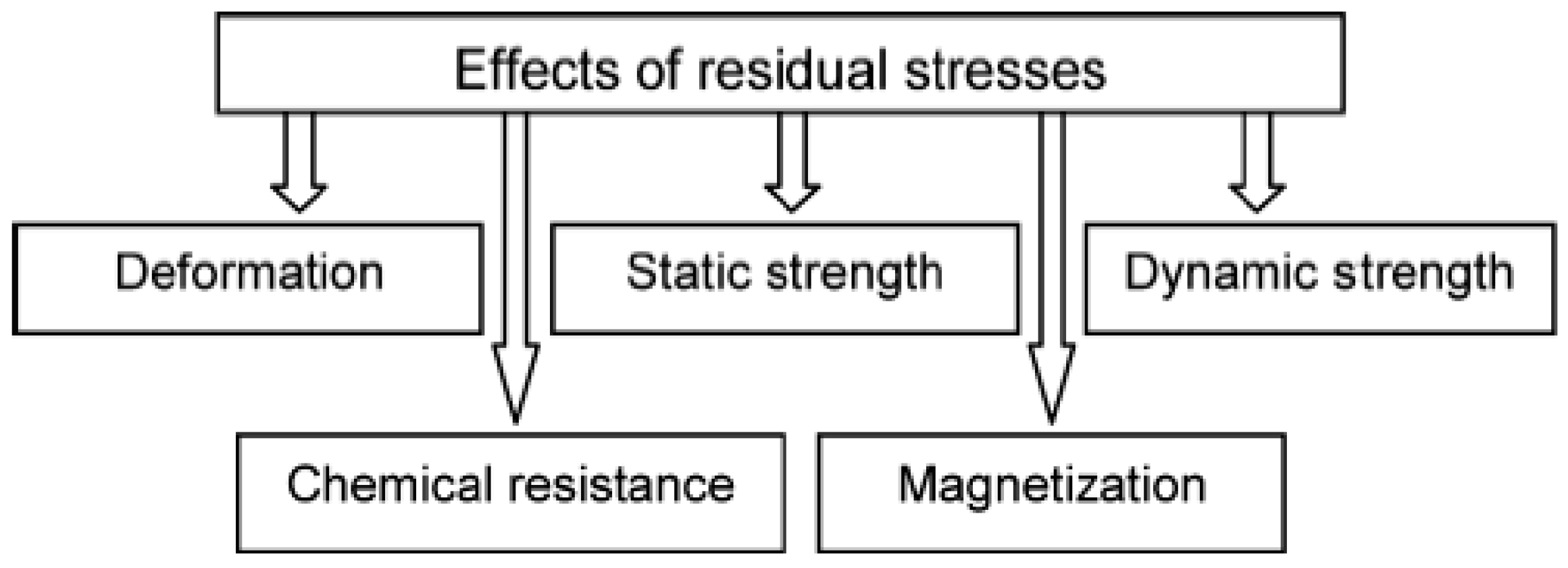
4. Part Functionality as Effected by Surface Residual Stress

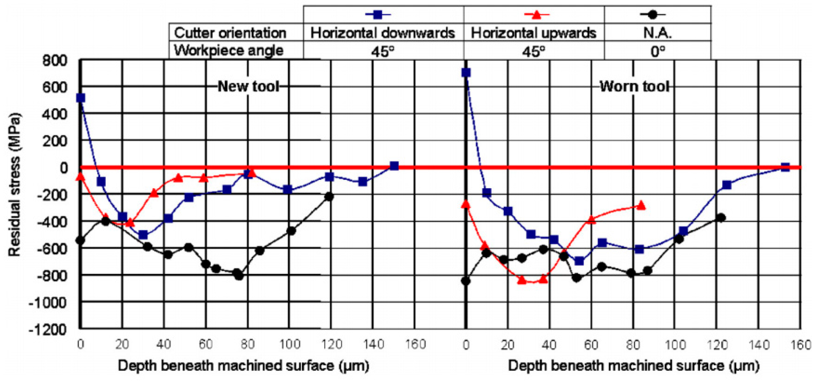
4.1. Residual Stress Characteristic on Machined Surface

Residual stresses are stresses that remain in a solid body after the external loading (mechanical and thermal) has been eliminated [83]. At the same time, the microstructure changes of machined surface can also cause residual stress [84]. Some scholars have studied the basic principle of residual stress caused by machining [33,85,86]. As far as 1982, Brinksmeier et al. have conducted such research. They reported the causes of residual stresses in machining process [87]. The final state of residual stress on the component has close relationships with other surface integrity factors, such as surface topography, subsurface microstructure, and topological states of a machined surface.
Considerable research on residual stress has been done for milling process. Titanium alloy is widely used in aerospace industry because of its high mechanical strength, chemical resistance, and thermal conductivity, so it is very important to control the distribution of residual stress. Sun et al. studied the surface integrity in the process of Ti-6Al-4V milling by the experimental method. It was found that the compressive residual normal stresses in the cutting and feed direction increase with the increase of cutting speed. Meanwhile, it is found that the compressive residual normal stress in feed direction is larger than that in cutting direction [88]. Rao et al. studied the milling of Ti-6-Al-4V titanium alloy and concluded that the compressive residual stress increased with the increase of feed and the cutting speed had no effect on the compressive residual stress [89]. For milling process of Inconel 718 with carbide K20, the increase of milling speed will enhance the tensile stress at the surface and compressive stress beneath the machined surface.
Aspinwall et al. used experimental methods to study the effect of tool positioning and workpiece angle on machining performance during milling Inconel 718. Compressive residual stress is generated in horizontal upward cutting and tensile residual stress is generated in horizontal downward cutting. The reason is that horizontal upward has a relatively low cutting speed, so the local temperature of the machined surface is lower. The influence of tool wear and cutting direction on residual stress is shown in Figure 7 [90]. Jiang et al. investigated the effects of tool diameters on the residual stress in the milling process of a thin-walled part. They found that the distribution of residual stress was more uniform as the tool diameter increased [91]. For milling process of nickel alloy and titanium alloy, many research results indicated that increasing cutting speed will bring about the tensile residual stresses tend to become more compressive [92]. Axinte et al. studied the residual stresses in the feed direction during milling AISI H13. It is found that cutting speed and feed per tooth are important factors affecting the residual stress on the surface [93]. When AISI H13 steel is hard milled by coated cutting tools, the investigated result of in-depth residual stress distribution showed that microstructural changes deeply affect the residual stress and that they have to be accurately taken into account during the process design [94]. Wang et al. [95] studied the effects of cutting parameters, cutting fluid, and spindle angle on residual stress during milling of Inconel 718 alloy. The results show that the cutting depth and cutting speed have great influence on the distribution of residual stress, and the residual stress in the tensile direction increases gradually with the increase of the spindle angle.
Although the experimental method can directly reflect the relationship between the distribution of residual stress and cutting conditions, it has higher cost and longer period. Therefore, it is urgent to develop a predictive model of residual stress distribution in milling process. Jiang et al. [96] used finite element simulation to study the distribution of residual stress in high-speed peripheral milling, and found that the cutting thickness had a significant impact on the tangential residual stress. Li et al. [97] used the finite element method to study the effect of cutting depth on the residual stress in milling, and pointed out that the residual stress can be reduced by optimizing the cutting depth of thin wall parts. Liang et al. [98] established an exponential decay function considering the flank wear, tool inclination, and depth of cut to predict the compressive residual stresses distribution of the milled TC17 alloy (An alpha-beta titanium alloy). Fergani et al. [99] used Neumann–Duhamel principle to establish the regeneration prediction model of residual stress in multipass machining under thermomechanical loading. Considering the three-dimensional instantaneous contact state between the milling cutter and the workpiece, Wan et al. [100] established the theoretical model for predicting the residual stress in the milling process. At the same time, it was observed that the thermal load had a relatively weak effect on the residual stress.
Residual stress is a crucial factor to evaluate surface integrity of the milled workpiece. In milling process, distribution of residual stresses is marginally affected by the cutting speed and tool wear state. Also, its residual distribution has close relationship with cutting strategy in milling process. To get reasonable distribution of residual stresses, the cutting parameters should be optimized with consideration of tool parameters.

4.2. Fatigue Resistance as Effected by Surface Residual Stress

The residual stress has an important effect on the mechanical properties of the workpiece. Residual stresses directly influence the deformation of workpiece, such as static and dynamic strength and chimerical and electrical properties, as shown in Figure 8. It is well known that surface finish and residual stress can significantly affect the antidestructive ability of the component under high cyclic fatigue load.
Compressive residual stress is usually advantageous to the fatigue life of machined parts, while residual tensile stress is the opposite. The tensile residual stress will enlarge or contribute the extension of microcrack. When the crack increases to a certain extent, it will cause workpiece failure. So, it is necessary to remove tensile residual stresses occurring during machining process. In view of the high speed milling process of Ti-10V-2Fe-3Al, Yao et al. [101] found that the fatigue life of the workpiece is more sensitive to residual stress than surface roughness. Similar results were found by Moussaoui et al. [41].
Influence of milling process on the fatigue life of Ti6-Al-4V was investigated by Moussaoui et al. They found that residual stress has a more preponderant influence on fatigue life than geometric and metallurgical parameters [102]. Huang et al. [55] studied the effect of different tool paths on the fatigue life of AISI H13 high-speed milling process. The results show that the different tool paths lead to the difference of effective residual stress, which results in different fatigue performance of the workpiece. Meanwhile, it is found that the influence of effective residual stress on the fatigue life of the workpiece is greater than that of the orientational surface topography. Yang et al. [103] studied the effect of residual stress on the fatigue life of workpieces during milling of Ti-6Al-4V. The results show that increasing the compressive residual stress can effectively improve the fatigue performance of the workpiece. However, when the workpiece surface material produces plastic deformation, the effect of residual stress will disappear.
Residual stress is a crucial factor to evaluate surface integrity of the milled workpiece. In milling process, distribution of residual stresses is marginally affected by the cutting speed and tool wear state. Also, its residual distribution has close relationship with cutting strategy in milling process. To get reasonable distribution of residual stresses, the cutting parameters should be optimized with consideration of tool parameters. If the distribution of residual stresses is not reasonable, it can be modified due by mechanical loads (static or cyclic) or thermal exposure [104].
The influence of residual stress and microstructure on the fatigue life of the workpiece was studied by F. Ghanem et al. By comparing electro-discharge machining (EDM) with the milling process, they found that the surfaces prepared by EDM showed a tensile residual stress at the surface. The milled surfaces showed a near-surface compressive residual stress, which is favorable for fatigue crack resistance, and the comparison result is shown in Figure 9 [105]. Three-point bending fatigue tests of the notched specimens revealed a loss of 35% in fatigue endurance in the case of EDM.
Tool wear is an unavoidable and complicated phenomenon occurring in machining process, which has a direct impact on residual stress on milled surface. For milling process, many workpiece materials contain carbide particles in their structure. As the cutting tool wears, some carbide particles in workpiece are removed from the machined surface sometimes, then there will be direct effect on the surface quality of the machined surface. Generally, tool flank wear was found to have the most effect on distribution of residual stress in high speed milling process.
Considerable research has been performed to get the effect of tool wear on part functionality. The effects of tool wear on surface integrity and fatigue life during milling was studied by Guo et al. They found that surface roughness is generally higher in the step-over direction than the feed direction and that tool wear does not necessarily affect the fatigue life within a certain range (0.2 mm) [106]. Also, fundamental relationship between tool wear and fatigue was related by them. They found that compared with the sharp tool, the worn tool up to flank wear (0.12 mm) only slightly reduces the average life from 1.23 × 10⁶ to 1.16 × 10⁶ cycles. Rougher surfaces are expected to encourage fatigue crack initiation. While Guo found that the surface roughness also has a slightly influence on four-point bending fatigue life for end milling of AISI H13 [42], and the effect of tool wear on workpiece fatigue life is shown in Figure 10.
The residual stress on milled surface will directly influence the generation and extension of crack on surface, and that will have a direct impact on fatigue life of workpiece. Generally, compressive residual stress contributes to the improvement of fatigue life. Tool wear has a direct impact on the residual stress of the milled surface, so tool wear is another important factor that influences the fatigue life of component in milling process.

5. Conclusions and Outlook

The optimization and control of machined surface integrity is the key technology to ensure the functional performance and service life of parts. The effects of cutting parameters such as cutting speed, feed speed, cutting depth, and tool wear on the machined surface integrity during milling are emphatically reviewed. At the same time, the research progress of the relationship between the machined surface integrity and the component use performance is also revealed. Researchers have made extensive research on the influence of machined surface integrity on fatigue properties and obtained a series of research results. However, there are still some urgent problems to be solved.
  • The effects of surface integrity on performance were mostly determined by experiments and could not be revealed effectively at the mechanism level.
  • No uniform standard has been formed to assess the effect of surface integrity parameters on fatigue performance, which limits the optimization of process parameters and the improvement of service performance of workpieces.
  • The local performance change, design, and service performance state of the parts could not be organically combined to form an interconnected mode.
  • Combined with the current research status and engineering application requirements, the following aspects can be emphatically studied in the future.
  • To strengthen theoretical research on fatigue performance optimization. The existing optimization models assume that the surface integrity evaluation indices (surface morphology, residual stress, microhardness, and metamorphic layer thickness) have the same effect on fatigue performance, so the weight of the coefficient of the optimization model is consistent. In order to make the optimization result more accurate, the corresponding mathematical analysis method can be considered to distinguish the weight of various indexes.
  • To strengthen the research on modeling technology of machined surface integrity and workpiece performance. The analytic model of residual stress of workpiece surface during milling is still a difficult problem. The reason is that the change of chip thickness on cutting edge is more complicated, which results in the nonlinear gradient distribution of cutting force and cutting temperature in machining process. Only some physical factors (vibration, tool/workpiece deformation, and cutting force) are considered in the analytical model of surface topography, while tool wear and the characteristics of interrupted cutting are not taken into account, so there is still a large error in the simulation results.
  • Development of new milling processes. The reasonable selection of process parameters directly affects the machined surface integrity and controls the workpiece performance. How to develop a new milling process based on different machining systems, processing environment, workpiece materials, and performance needs to be further explored.
  • The relationship between the design-manufacturing-service performance of parts is explored. A complete interconnected mode of design, manufacturing, and service performance evaluation of parts was established.
  • The theoretical analysis and experimental research on the response relationship between high temperature fatigue, vibration fatigue, corrosion fatigue performance, and surface integrity of processing under environmental conditions are further improved.

Author Contributions

The idea of this project was conceived by C.Y. C.Y and H.G. consulted to relevant high-level papers on aspects of changes in surface integrity caused by changes in the milling process, and wrote this project. X.L. and S.Y.L. reviewed this project and proposed constructive guidance to make the article more complete.

Funding

This research was funded by the National Natural Science Foundation of China (Grant No. 51575147) and the Science Funds for the Young Innovative Talents of HUST (No. 201507), and the International Cooperation and Exchanges NSFC (No.51720105009).

Conflicts of Interest

The authors declare no conflicts of interest.

References

  1. Field, M.; Kahles, J.F.; Cammett, J. Review of measuring methods for surface integrity. CIRP 1972, 21, 219–238. [Google Scholar]
  2. Field, M.; Kahles, J.F. Review of Surface Integrity of Machined Components; Defense Technical Information Center: Fort Belvoir, VA, USA, 1971. [Google Scholar]
  3. Field, M.; Kahles, J. The surface integrity of machined-and ground high-strength steels. DIMC Rep. 1946, 210, 54–58. [Google Scholar]
  4. Yue, C.; Liu, X.; Ma, J.; Liu, Z. Hardening effect on machined surface for precise hard cutting process with consideration of tool wear. Chin. J. Mech. Eng. 2014, 27, 1249–1256. [Google Scholar] [CrossRef]
  5. Yue, C.; Liu, X. Research progress of machined surface integrity for high stress steel cutting process. J. Harbin Univ. Sci. Technol. 2012, 16, 5–10. [Google Scholar]
  6. Jawahir, I.; Brinksmeier, E.; M’saoubi, R.; Aspinwall, D.; Outeiro, J.; Meyer, D.; Umbrello, D.; Jayal, A. Surface integrity in material removal processes: Recent advances. CIRP Ann. Manuf. Technol. 2011, 60, 603–626. [Google Scholar] [CrossRef]
  7. Ulutan, D.; Ozel, T. Machining induced surface integrity in titanium and nickel alloys: A review. Int. J. Mach. Tool Manuf. 2011, 51, 250–280. [Google Scholar] [CrossRef]
  8. Davim, J.P. Surface Integrity in Machining; Springer: Berlin, Germany, 2010. [Google Scholar]
  9. Klocke, F.; Brinksmeier, E.; Weinert, K. Capability profile of hard cutting and grinding processes. CIRP Ann. Manuf. Technol. 2005, 54, 22–45. [Google Scholar] [CrossRef]
  10. M’Saoubi, R.; Outeiro, J.; Chandrasekaran, H.; Dillon, O.; Jawahir, I. A review of surface integrity in machining and its impact on functional performance and life of machined products. Int. J. Sustain. Manuf. 2008, 1, 203–236. [Google Scholar] [CrossRef]
  11. Aris, N.; Cheng, K. Characterization of the surface functionality on precision machined engineering surfaces. Int. J. Adv. Manuf. Technol. 2008, 38, 402–409. [Google Scholar] [CrossRef]
  12. Budak, E. Analytical models for high performance milling. Part I: Cutting forces, structural deformations and tolerance integrity. Int. J. Mach. Tool Manuf. 2006, 46, 1478–1488. [Google Scholar] [CrossRef] [Green Version]
  13. Zhang, S.; Guo, Y. Taguchi method based process space for optimal surface topography by finish hard milling. J. Manuf. Sci. Eng. ASME 2009, 131, 051003. [Google Scholar] [CrossRef]
  14. Wang, Z.; Yuan, J.; Yin, Z.; Hu, X. Surface topography and roughness of high-speed milled AlMn1Cu. Chin. J. Mech. Eng. 2016, 29, 1200–1207. [Google Scholar] [CrossRef]
  15. Ghani, J.A.; Choudhury, I.; Hassan, H. Application of Taguchi method in the optimization of end milling parameters. J. Mater. Process. Technol. 2004, 145, 84–92. [Google Scholar] [CrossRef]
  16. Li, Z.L.; Zhu, L.M. Envelope surface modeling and tool path optimization for five-axis flank milling considering cutter runout. J. Manuf. Sci. Eng. ASME 2014, 136, 041021. [Google Scholar] [CrossRef]
  17. Denkena, B.; Böß, V.; Nespor, D.; Gilge, P.; Hohenstein, S.; Seume, J. Prediction of the 3D Surface Topography after Ball End Milling and its Influence on Aerodynamics. Procedia CIRP 2015, 31, 221–227. [Google Scholar] [CrossRef]
  18. Zhang, C.; Guo, S.; Zhang, H.; Zhou, L. Modeling and predicting for surface topography considering tool wear in milling process. Int. J. Adv. Manuf. Technol. 2013, 68, 2849–2860. [Google Scholar] [CrossRef]
  19. Irene, B.C.; Joan, V.C.; Alejandro, D.F. Surface topography in ball-end milling processes as a function of feed per tooth and radial depth of cut. Int. J. Mach. Tool Manuf. 2012, 53, 151–159. [Google Scholar]
  20. Gao, Y.; Sun, R.; Chen, Y.; Leopold, J. Analysis of chip morphology and surface topography in modulation assisted machining. Int. J. Mech. Sci. 2016, 111, 88–100. [Google Scholar] [CrossRef]
  21. Arizmendi, M.; Campa, F.J.; Fernández, J.; Gil, A.; Bilbao, E.; Veiga, F.; Lamikiz, A. Model for surface topography prediction in peripheral milling considering tool vibration. CIRP Ann. Manuf. Technol. 2009, 58, 93–96. [Google Scholar] [CrossRef]
  22. Lazoglu, I. 3D surface topography analysis in 5-axis ball-end milling. CIRP Ann. Manuf. Technol. 2017, 66, 133–136. [Google Scholar]
  23. Zhang, W.H.; Tan, G.; Wan, M.; Gao, T. A new algorithm for the numerical simulation of machined surface topography in multiaxis ball-end milling. J. Manuf. Sci. Eng. ASME 2008, 130, 284. [Google Scholar] [CrossRef]
  24. Gao, T.; Zhang, W.; Qiu, K.; Wan, M. Numerical simulation of machined surface topography and roughness in milling process. J. Manuf. Sci. Eng. ASME 2006, 128, 96–103. [Google Scholar] [CrossRef]
  25. Tan, L.; Yao, C.; Ren, J.; Zhang, D. Effect of cutter path orientations on cutting forces, tool wear, and surface integrity when ball end milling TC17. Int. J. Adv. Manuf. Technol. 2016, 88, 1–14. [Google Scholar] [CrossRef]
  26. Chen, X.; Zhao, J.; Dong, Y.; Li, A.; Wang, D. Research on the machined surface integrity under combination of various inclination angles in multi-axis ball end milling. Proc. Inst. Mech. Eng. B J. Eng. 2014, 228, 31–50. [Google Scholar] [CrossRef]
  27. Lu, X.; Hu, X.; Jia, Z.; Liu, M.; Gao, S.; Qu, C. Model for the prediction of 3D surface topography and surface roughness in micro-milling Inconel 718. Int. J. Adv. Manuf. Technol. 2017, 94, 2043–2056. [Google Scholar] [CrossRef]
  28. Brito, T.G.; Paiva, A.P.; Ferreira, J.R.; Balestrassi, P. A normal boundary intersection approach to multiresponse robust optimization of the surface roughness in end milling process with combined arrays. Precis. Eng. 2014, 38, 628–638. [Google Scholar] [CrossRef]
  29. Tangjitsitcharoen, S.; Thesniyom, P.; Ratanakuakangwan, S. Prediction of surface roughness in ball-end milling process by utilizing dynamic cutting force ratio. J. Intell. Manuf. 2017, 28, 13–21. [Google Scholar] [CrossRef]
  30. Benardos, P.; Vosniakos, G.-C. Predicting surface roughness in machining: A review. Int. J. Mach. Tool Manuf. 2003, 43, 833–844. [Google Scholar] [CrossRef]
  31. Benardos, P.; Vosniakos, G.C. Prediction of surface roughness in CNC face milling using neural networks and Taguchi’s design of experiments. Robot. Comput. Integr. Manuf. 2002, 18, 343–354. [Google Scholar] [CrossRef]
  32. Toh, C.K. Surface topography analysis in high speed finish milling inclined hardened steel. Precis. Eng. 2004, 28, 386–398. [Google Scholar] [CrossRef]
  33. Ginting, A.; Nouari, M. Surface integrity of dry machined titanium alloys. Int. J. Mach. Tool Manuf. 2009, 49, 325–332. [Google Scholar] [CrossRef]
  34. Yang, H.; Chen, Z.; Zhou, Z. Influence of cutting speed and tool wear on the surface integrity of the titanium alloy Ti-1023 during milling. Int. J. Adv. Manuf. Technol. 2015, 78, 1113–1126. [Google Scholar]
  35. Du, J.; Liu, Z.; Lv, S. Deformation-phase transformation coupling mechanism of white layer formation in high speed machining of FGH95 Ni-based superalloy. Appl. Surf. Sci. 2014, 292, 197–203. [Google Scholar] [CrossRef]
  36. Xue, C.; Chen, W.Y. Surface damages generated in hole making of a cast nickel-based alloy. Mater. Sci. Forum 2012, 697, 57–60. [Google Scholar]
  37. Blotter, L.K.G.P.T. The formation and properties of machining burrs. J. Eng. Ind. 1976, 98, 66–74. [Google Scholar]
  38. Novovic, D.; Dewes, R.; Aspinwall, D.; Voice, W.; Bowen, P. The effect of machined topography and integrity on fatigue life. Int. J. Mach. Tool Manuf. 2004, 44, 125–134. [Google Scholar] [CrossRef]
  39. Chrzanowski, W.; Neel, E.A.A.; Armitage, D.A.; Knowles, J. Effect of surface treatment on the bioactivity of nickel–titanium. Acta Biomater. 2008, 4, 1969–1984. [Google Scholar] [CrossRef] [PubMed]
  40. Arola, D.; Williams, C.L. Estimating the fatigue stress concentration factor of machined surfaces. Int. J. Fatigue 2002, 24, 923–930. [Google Scholar] [CrossRef]
  41. Moussaoui, K.; Mousseigne, M.; Senatore, J.; Chieragatti, R. The effect of roughness and residual stresses on fatigue life time of an alloy of titanium. Int. J. Adv. Manuf. Technol. 2015, 78, 557–563. [Google Scholar] [CrossRef]
  42. Li, W.; Guo, Y.; Guo, C. Superior surface integrity by sustainable dry hard milling and impact on fatigue. CIRP Ann. Manuf. Technol. 2013, 62, 567–570. [Google Scholar] [CrossRef]
  43. Li, X.; Zhao, P.; Niu, Y.; Guan, C. Influence of finish milling parameters on machined surface integrity and fatigue behavior of Ti1023 workpiece. Int. J. Adv. Manuf. Technol. 2017, 91, 1297–1307. [Google Scholar] [CrossRef]
  44. Wang, X.; Huang, C.; Zou, B.; Liu, G.; Zhu, H. Experimental study of surface integrity and fatigue life in the face milling of inconel 718. Front. Mech. Eng. 2018, 13, 243–250. [Google Scholar] [CrossRef]
  45. Noll, G.C.; Erickson, G.C. Allowable stresses for steel members of finite life. Proc. Soc. Experts Stress Anal. 1948, 5, 132–143. [Google Scholar]
  46. McKelvey, S.A.; Fatemi, A. Surface finish effect on fatigue behavior of forged steel. Int. J. Fatigue 2012, 36, 130–145. [Google Scholar] [CrossRef]
  47. De Chiffre, L.; Christiansen, S.; Skade, S. Advantages and industrial applications of three-dimensional surface roughness analysis. CIRP Ann. Manuf. Technol. 1994, 43, 473–478. [Google Scholar] [CrossRef]
  48. Waikar, R.A.; Guo, Y.B. A comprehensive characterization of 3D surface topography induced by hard turning versus grinding. J. Mater. Process. Technol. 2008, 197, 189–199. [Google Scholar] [CrossRef]
  49. Yang, D.; Liu, Z.; Xiao, X.; Xie, F. The Effects of Machining-induced Surface Topography on Fatigue Performance of Titanium Alloy Ti-6Al-4V. Procedia CIRP 2018, 71, 27–30. [Google Scholar] [CrossRef]
  50. Dong, W.; Sullivan, P.; Stout, K. Comprehensive study of parameters for characterizing three-dimensional surface topography: III: Parameters for characterizing amplitude and some functional properties. Wear 1994, 178, 29–43. [Google Scholar] [CrossRef]
  51. Novovic, D.; Aspinwall, D.K.; Dewes, R.C.; Bowen, P.; Griffiths, B. The effect of surface and subsurface condition on the fatigue life of Ti–25V–15Cr–2Al–0.2 C% wt alloy. CIRP Ann. Manuf. Technol. 2016, 65, 523–528. [Google Scholar] [CrossRef]
  52. Piska, M.; Ohnistova, P.; Hornikova, J.; Hervoches, C. A Study of Progressive Milling Technology on Surface Topography and Fatigue Properties of the High Strength Aluminum Alloy 7475-T7351. In Proceedings of the International Conference on New Trends in Fatigue and Fracture, Cancun, Mexico, 25–27 October 2017; Springer: Cham, Switzerland, 2017; pp. 7–17. [Google Scholar]
  53. Taylor, D.; Clancy, O. The fatigue performance of machined surfaces. Fatigue Fract. Eng. Mater. Struct. 1991, 14, 329–336. [Google Scholar] [CrossRef]
  54. Huang, W.; Zhao, J.; Xing, A.; Wang, G.; Tao, H. Influence of tool path strategies on fatigue performance of high-speed ball-end-milled AISI H13 steel. Int. J. Adv. Manuf. Technol. 2018, 94, 371–380. [Google Scholar] [CrossRef]
  55. Sedlaček, M.; Podgornik, B.; Vižintin, J. Influence of surface preparation on roughness parameters, friction and wear. Wear 2009, 266, 482–487. [Google Scholar] [CrossRef]
  56. Menezes, P.L.; Kailas, S.V. Effect of surface roughness parameters and surface texture on friction and transfer layer formation in tin–steel tribo-system. J. Mater. Process. Technol. 2008, 208, 372–382. [Google Scholar] [CrossRef]
  57. Magri, M.L.; Diniz, A.E.; Button, S.T. Influence of surface topography on the wear of hot forging dies. Int. J. Adv. Manuf. Technol. 2013, 65, 459–471. [Google Scholar] [CrossRef]
  58. Deng, W.J.; Xia, W.; Li, C.; Tang, Y. Formation of ultra-fine grained materials by machining and the characteristics of the deformation fields. J. Mater. Process. Technol. 2009, 209, 4521–4526. [Google Scholar] [CrossRef]
  59. Umbrello, D. Investigation of surface integrity in dry machining of Inconel 718. Int. J. Adv. Manuf. Technol. 2013, 69, 2183–2190. [Google Scholar] [CrossRef]
  60. Ramesh, A.; Melkote, S.N. Modeling of white layer formation under thermally dominant conditions in orthogonal machining of hardened AISI 52100 steel. Int. J. Mach. Tool Manuf. 2008, 48, 402–414. [Google Scholar] [CrossRef]
  61. Elbestawi, M.; Chen, L.; Becze, C.; El-Wardany, T. High-speed milling of dies and molds in their hardened state. CIRP Ann. Manuf. Technol. 1997, 46, 57–62. [Google Scholar] [CrossRef]
  62. Zhang, S.; Li, W.; Guo, Y. Process design space for optimal surface integrity in finish hard milling of tool steel. Prod. Eng. 2012, 6, 355–365. [Google Scholar] [CrossRef]
  63. Li, A.; Zhao, J.; Dong, Y.; Wang, D.; Chen, X. Surface integrity of high-speed face milled Ti-6Al-4V alloy with PCD tools. Mach. Sci. Technol. 2013, 17, 464–482. [Google Scholar] [CrossRef]
  64. Devillez, A.; le Coz, G.; Dominiak, S.; Dudzinski, D. Dry machining of Inconel 718 workpiece surface integrity. J. Mater. Process. Technol. 2011, 211, 1590–1598. [Google Scholar] [CrossRef]
  65. Pan, Z.; Liang, S.Y.; Garmestani, H.; Shih, D.S. Prediction of machining-induced phase transformation and grain growth of Ti-6Al-4 V alloy. Int. J. Adv. Manuf. Technol. 2016, 87, 859–866. [Google Scholar] [CrossRef]
  66. Chou, Y.K.; Evans, C.J. White layers and thermal modeling of hard turned surfaces. Int. J. Mach. Tool Manuf. 1999, 39, 1863–1881. [Google Scholar] [CrossRef]
  67. Swaminathan, S.; Shankar, M.R.; Lee, S.; Hwang, J.; King, A.H.; Kezar, R.F.; Rao, B.C.; Brown, T.L.; Chandrasekar, S.; Compton, W.D.; et al. Large strain deformation and ultra-fine grained materials by machining. Mater. Sci. Eng. A 2005, 410, 358–363. [Google Scholar] [CrossRef]
  68. Wang, Q.; Liu, Z.; Yang, D.; Mohsan, A. Metallurgical-based prediction of stress-temperature induced rapid heating and cooling phase transformations for high speed machining Ti-6Al-4V alloy. Mater. Des. 2017, 119, 208–218. [Google Scholar] [CrossRef]
  69. Li, A.; Pang, J.; Zhao, J.; Zang, J.; Wang, F. FEM-simulation of machining induced surface plastic deformation and microstructural texture evolution of Ti-6Al-4V alloy. Int. J. Mech. Sci. 2017, 123, 214–223. [Google Scholar] [CrossRef]
  70. Thomas, M.; Turner, S.; Jackson, M. Microstructural damage during high-speed milling of titanium alloys. Scr. Mater. 2010, 62, 250–253. [Google Scholar] [CrossRef]
  71. Shyha, I.; Gariani, S.; El-Sayed, M.A.; Huo, D. Analysis of Microstructure and Chip Formation When Machining Ti-6Al-4V. Metals 2018, 8, 185. [Google Scholar] [CrossRef]
  72. Li, B.; Zhang, S.; Yan, Z.; Jiang, D. Influence of edge hone radius on cutting forces, surface integrity, and surface oxidation in hard milling of AISI H13 steel. Int. J. Adv. Manuf. Technol. 2018, 95, 1153–1164. [Google Scholar] [CrossRef]
  73. Liu, B.; Zhou, X.; Hashimoto, T.; Zhang, X.; Wang, J. Machining introduced microstructure modification in aluminium alloys. J. Alloys Compd. 2018, 757, 233–238. [Google Scholar] [CrossRef]
  74. Aramcharoen, A.; Mativenga, P. White layer formation and hardening effects in hard turning of H13 tool steel with CrTiAlN and CrTiAlN/MoST-coated carbide tools. Int. J. Adv. Manuf. Technol. 2008, 36, 650–657. [Google Scholar] [CrossRef]
  75. Lu, Y.; Guo, C. Finite element modeling of multi-pass machining of Inconel 718. In Proceedings of the CD 2009 ASME International Conference on Manufacturing Science and Engineering, West Lafayette, IN, USA, 4–7 October 2009; pp. 84081–84086. [Google Scholar]
  76. Wu, G.Q.; Shi, C.L.; Sha, W.; Sha, A.; Jiang, H. Effect of microstructure on the fatigue properties of Ti–6Al–4V titanium alloys. Mater. Des. 2013, 46, 668–674. [Google Scholar] [CrossRef] [Green Version]
  77. Sealy, M.P.; Guo, Y.B.; Caslaru, R.C.; Sharkins, J.; Feldman, D. Fatigue performance of biodegradable magnesium–calcium alloy processed by laser shock peening for orthopedic implants. Int. J. Fatigue 2016, 82, 428–436. [Google Scholar] [CrossRef] [Green Version]
  78. Fellah, M.; Samad, M.A.; Labaiz, M.; Assala, O.; Iost, A. Sliding friction and wear performance of the nano-bioceramic α-Al2O3 prepared by high energy milling. Tribol. Int. 2015, 91, 151–159. [Google Scholar] [CrossRef]
  79. Pang, J. Investigation on Texture Simulation and Friction Characteristics of Machined Surface of Titanium Alloy. Ph.D. Thesis, Shandong University, Shandong, China, 2017. [Google Scholar]
  80. Huang, W.; Zhao, J.; Ai, X.; Wang, G. Influence of tool path strategies on friction and wear behavior of high-speed ball-end-milled hardened AISI D2 steel. Int. J. Adv. Manuf. Technol. 2018, 96, 2769–2779. [Google Scholar] [CrossRef]
  81. Zhong, Z. Surface Integrity and Corrosion Resistance in High Speed Milling Aluminum Alloy 7050-T7451. Ph.D. Thesis, Shandong University, Shandong, China, 2015. [Google Scholar]
  82. Kim, D.; Kim, B.; Kang, C. Estimation of die service life for a die cooling method in a hot forging process. Int. J. Adv. Manuf. Technol. 2005, 27, 33–39. [Google Scholar] [CrossRef]
  83. Guo, Y.; Li, W.; Jawahir, I. Surface integrity characterization and prediction in machining of hardened and difficult-to-machine alloys: A state-of-art research review and analysis. Mach. Sci. Technol. 2009, 13, 437–470. [Google Scholar] [CrossRef]
  84. Arnone, M. High Performance Machining; Hanser Gardner Publications: Cincinnati, OH, USA, 1998. [Google Scholar]
  85. Arunachalam, R.; Mannan, M.; Spowage, A. Surface integrity when machining age hardened Inconel 718 with coated carbide cutting tools. Int. J. Mach. Tool Manuf. 2004, 44, 1481–1491. [Google Scholar] [CrossRef]
  86. Arunachalam, R.; Mannan, M.; Spowage, A. Residual stress and surface roughness when facing age hardened Inconel 718 with CBN and ceramic cutting tools. Int. J. Mach. Tool Manuf. 2004, 44, 879–887. [Google Scholar] [CrossRef]
  87. Brinksmeier, E.; Cammett, J.; König, W.; Leskovar, P. Residual stresses—Measurement and causes in machining processes. CIRP Ann. Manuf. Technol. 1982, 31, 491–510. [Google Scholar] [CrossRef]
  88. Sun, J.; Guo, Y. A comprehensive experimental study on surface integrity by end milling Ti–6Al–4V. J. Mater. Process. Technol. 2009, 209, 4036–4042. [Google Scholar] [CrossRef]
  89. Rao, B.; Dandekar, C.R.; Shin, Y.C. An experimental and numerical study on the face milling of Ti–6Al–4V alloy: Tool performance and surface integrity. J. Mater. Process. Technol. 2011, 211, 294–304. [Google Scholar] [CrossRef]
  90. Aspinwall, D.K.; Dewes, R.C.; Ng, E.G.; Sage, C.; Soo, S.L. The influence of cutter orientation and workpiece angle on machinability when high-speed milling Inconel 718 under finishing conditions. Int. J. Mach. Tool Manuf. 2007, 47, 1839–1846. [Google Scholar] [CrossRef]
  91. Jiang, X.; Li, B.; Yang, J.; Zuo, X.Y. Effects of tool diameters on the residual stress and distortion induced by milling of thin-walled part. Int. J. Adv. Manuf. Technol. 2013, 68, 175–186. [Google Scholar] [CrossRef]
  92. Sridhar, B.; Devananda, G.; Ramachandra, K.; Bhat, R. Effect of machining parameters and heat treatment on the residual stress distribution in titanium alloy IMI-834. J. Mater. Process. Technol. 2003, 139, 628–634. [Google Scholar] [CrossRef]
  93. Axinte, D.; Dewes, R. Surface integrity of hot work tool steel after high speed milling-experimental data and empirical models. J. Mater. Process. Technol. 2002, 127, 325–335. [Google Scholar] [CrossRef]
  94. Zhang, S.; Ding, T.; Li, J. Determination of surface and in-depth residual stress distributions induced by hard milling of H13 steel. Prod. Eng. 2012, 6, 375–383. [Google Scholar] [CrossRef]
  95. Wang, J.; Zhang, D.; Wu, B.; Luo, M. Residual stresses analysis in ball end milling of nickel-based Superalloy Inconel 718. Mater. Res. 2017, 20, 1681–1689. [Google Scholar] [CrossRef]
  96. Jiang, X.; Li, B.; Yang, J.; Zuo, X.; Li, K. An approach for analyzing and controlling residual stress generation during high-speed circular milling. Int. J. Adv. Manuf. Technol. 2013, 66, 1439–1448. [Google Scholar] [CrossRef]
  97. Li, B.; Jiang, X.; Yang, J.; Liang, S.Y. Effects of depth of cut on the redistribution of residual stress and distortion during the milling of thin-walled part. J. Mater. Process. Technol. 2015, 216, 223–233. [Google Scholar] [CrossRef]
  98. Liang, T.; Zhang, D.; Yao, C.; Wu, D.; Zhang, J. Evolution and empirical modeling of compressive residual stress profile after milling, polishing and shot peening for TC17 alloy. J. Manuf. Process. 2017, 26, 155–165. [Google Scholar]
  99. Fergani, O.; Jiang, X.; Shao, Y.; Welo, T.; Yang, J. Prediction of residual stress regeneration in multi-pass milling. Int. J. Adv. Manuf. Technol. 2016, 83, 1153–1160. [Google Scholar] [CrossRef]
  100. Wan, M.; Ye, X.Y.; Yang, Y.; Zhang, W. Theoretical prediction of machining-induced residual stresses in three-dimensional oblique milling processes. Int. J. Mech. Sci. 2017, 133, 426–437. [Google Scholar] [CrossRef]
  101. Yao, C.F.; Tan, L.; Ren, J.X.; Lin, Q. Surface integrity and fatigue behavior for high-speed milling Ti–10V–2Fe–3Al titanium alloy. J. Fail. Anal. Prev. 2014, 14, 102–112. [Google Scholar] [CrossRef]
  102. Moussaoui, K.; Mousseigne, M.; Senatore, J.; Chieragatti, R. Influence of milling on the fatigue lifetime of a Ti6Al4V titanium alloy. Metals 2015, 5, 1148–1162. [Google Scholar] [CrossRef]
  103. Yang, D.; Liu, Z. Surface integrity generated with peripheral milling and the effect on low-cycle fatigue performance of aeronautic titanium alloy Ti-6Al-4V. Aeronaut. J. 2018, 122, 316–332. [Google Scholar] [CrossRef]
  104. McClung, R. A literature survey on the stability and significance of residual stresses during fatigue. Fatigue Fract. Eng. Mater. 2007, 30, 173–205. [Google Scholar] [CrossRef]
  105. Ghanem, F.; Sidhom, H.; Braham, C.; Fitzpatrick, M. Effect of near-surface residual stress and microstructure modification from machining on the fatigue endurance of a tool steel. J. Mater. Eng. Perform. 2002, 11, 631–639. [Google Scholar] [CrossRef]
  106. Li, W.; Guo, Y.; Barkey, M.; Jordon, J. Effect tool wear during end milling on the surface integrity and fatigue life of Inconel 718. Procedia CIRP 2014, 14, 546–551. [Google Scholar] [CrossRef]
Figure 1. The effect of surface integrity on part functionality.
Applsci 08 02550 g001
Figure 2. Surface topography of milling surface [13]. (a) Surface texture zones in milling and (b) surface topography by milling process.
Applsci 08 02550 g002
Figure 3. Effect of different cutter path orientations on surface topography [25]: (a) Vertical upward; (b) vertical downward; (c) horizontal upward; and (d) horizontal vertical downward.
Applsci 08 02550 g003
Figure 4. Three kinds of tearing surface [34]. (a) Microvoids and scratches; (b) microvoids and scratches; and (c) groove and pitting corrosion.
Applsci 08 02550 g004
Figure 5. Four types of surfaces topography and die flash land after forging [57]. Profiles of the die flash land surfaces under (a) condition 1, (b) condition 2, (c) condition 3, and (d) condition 4; Die flash land after forging under (e) condition 1, (f) condition 2, (g) condition 3, and (h) condition 4.
Applsci 08 02550 g005
Figure 6. Effects of cutting speed and tool wear on subsurface microstructure [34]. (a) VB = 0 m and (b) Vc = 60 m min−1, fz = 0.08 mm/tooth, ap = 1 mm.
Applsci 08 02550 g006
Figure 7. Effect of different cutter orientations/workpiece tilt angle on residual stress [90].
Applsci 08 02550 g007
Figure 8. Effect of residual stress on workpiece performance.
Applsci 08 02550 g008
Figure 9. Comparison effects of residual stress on fatigue life between electro-discharge machining and milling [105].
Applsci 08 02550 g009
Figure 10. Fatigue life vs. tool wear and fatigue fracture pattern [42].
Applsci 08 02550 g010

