Article

Optimal Collision-Free Grip Planning for Biped Climbing Robots in Complex Truss Environment

1
School of Electromechanical Engineering, Guangdong University of Technology, Guangzhou 510006, China
2
Key Laboratory of Biomimetic Robots and Systems, Ministry of Education, Beijing Institute of Technology, Beijing 100081, China
3
Department of Computing Science, University of Alberta, Edmonton, AB T6G2H1, Canada
*
Author to whom correspondence should be addressed.
Appl. Sci. 2018, 8(12), 2533; https://doi.org/10.3390/app8122533
Submission received: 2 November 2018 / Revised: 28 November 2018 / Accepted: 4 December 2018 / Published: 7 December 2018
(This article belongs to the Special Issue Advanced Mobile Robotics)

Abstract

:
Biped climbing robots (BiCRs) can overcome obstacles and perform transition easily thanks to their superior flexibility. However, to move in a complex truss environment, grips from the original point to the destination, as a sequence of anchor points along the route, are indispensable. In this paper, a grip planning method is presented for BiCRs generating optimal collision-free grip sequences, as a continuation of our previous work on global path planning. A mathematic model is firstly built up for computing the operational regions for negotiating obstacle members. Then a grip optimization model is proposed to determine the grips within each operational region for transition or for obstacle negotiation. This model ensures the total number of required climbing steps is minimized and the transition grips are with good manipulability. Lastly, the entire grip sequence satisfying the robot kinematic constraint is generated by a gait interpreter. Simulations are conducted with our self-developed biped climbing robot (Climbot), to verify the effectiveness and efficiency of the proposed methodology.

1. Introduction

Spatial trusses consisting of members are widely used in the construction of roofs, towers, bridges, and the like. However, so far truss-associated routine tasks such as construction, painting, inspection, maintenance, and so on rely highly on manual labor. These routine tasks are usually high-rise and high-intensity, signifying a great risk to workers’ safety. Thus, a kind of biped climbing robot has been designed as an ideal assistant or substitute for human workers carrying out these tasks. Typical representatives of BiCRs include SM2 [1], ROMA [2], Shady3D [3], 3DCLIMBER [4,5], PoleClimbingRobot [6] and Treebot [7]. These BiCRs generally comprise of an arm-like serial body for locomotion and grippers at both ends for attachment. Thanks to their biped climbing patterns, BiCRs can agilely move in complex 3D truss environments. Motivated by these characteristics, we also developed a biped climbing robot [8], named Climbot as shown in Figure 1. For the system implementation details and the climbing performance of Climbot, refer to [9].
To complete a given task, for example inspecting the connection reliability of truss joints, BiCRs must be capable of motion planning. Basically, the motion planning of BiCRs consists of grip planning and single-step motion planning [10]. In the grip planning procedure, a list of discrete grip locations, following which robots can navigate from the starting point to the destination, is determined. While in the single-step motion planning procedure, the shifting motion between adjacent grips is generated. It should be noted that not only the grips but also the single-step shifting motion must be free of collision. In this paper, we focus on the study of collision-free grip planning, assuming the truss environment is known or captured with integrated sensors such as in [11].
Figuring out the grip sequences in a 3D truss environment is challenging for BiCRs. Besides the demand for collision avoidance, grips must satisfy the robot kinematic constraints for continuous cycles of climbing from the point of view of reachability. Furthermore, grips should contribute to the formation of a reasonable combination of various gaits with corresponding step lengths, to save the climbing time and energy.
The grip sequences to BiCRs are like the footprint sequences to humanoid robots. Therefore, we can learn from the foot placement problem of humanoid robots that has been addressed in the literature. There are two families of approaches for solving the humanoid robot foot placement problem, which is based on discrete search and continuous optimization, respectively. The discrete search methods normally require a pre-generated set of potential footprints before planning. Then classical methods, such as A * and RRT, are commonly used for searching. Based on the terrain map and a discrete set of footstep placement positions, Kuffner [12,13] presented a global dynamic programming approach using greedy heuristics to plan safe navigation strategies for biped robots moving in obstacle-cluttered environments. Chestnutt et al. [14,15] used an A * search algorithm to generate a sequence of collision-free footstep locations to reach a given goal state. A tiered planning strategy was introduced in [16] that split the planner into three layers to traverse different terrain types. Ayaz et al. [17,18] presented a global reactive footstep planning strategy based upon a humanistic approach, in which a heuristic cost based on the complexity of stepping motion was used to assign foot placements and an exhaustive search was employed to identify the best path. These approaches can easily handle obstacle avoidance but introduce the trade-off between computational efficiency and solution precision. The continuous optimization approaches operate directly on the poses of the footsteps as continuous decision variables. Thus, it can make up for the precision deficiency of the discrete search methods. In [19,20], the authors presented a novel footstep optimization method with mixed-integer convex constraints that could solve the problem to its global optimum. However, the generation of each reachable region deeply relied on the position of the previous step, increasing the time consumption. In addition, adjusting the parameters to approximate the reachable regions was always difficult and thus reduced the planning accuracy. Guan et al. [21,22] built global optimization models with non-linear constraints to find the maximum heights of the obstacles that can be overcome. The results were then used as a priori knowledge and a database for surmounting obstacles. However, they focused on how to stride across one obstacle only, but not generating the nearby footprint sequences. Please note that these footstep planning methods for humanoid robots are always applied in 2D or 2.5D environments, which differs from the grip planning for BiCRs in complex 3D truss environments.
To the best of our knowledge, the collision-free grip planning problem has rarely been studied in the literature. Balaguer et al. [2,23] treated the BiCRs’ climbing path planning as a TSP-like problem. They modeled the environment as a graph with two categories of primitives. They then proposed a heuristic algorithm to solve the climbing path, along which the robot visited all beam faces without repetition. Detweiler et al. [24] presented a path planning algorithm to optimize the locomotion sequences for the Shady3D robot. A set of potential gripping points was first dispersed in the truss environment up to a certain density. Then the shortest locomotion sequence represented with gripping points was computed with the Dijkstra’s distance. Based on the framework of conventional genetic algorithm, Chung et al. [25] adopted the concept of genetic modification to design a new genetic operator. They used this method to solve the climbing path with the minimum energy demand. However, these methods all suffer limitations from spending long planning time, ignoring specific transition movement, and not thinking about obstacle avoidance. Lam et al. [7] discretized the tree surface into finite grasp points, then used a dynamic programming algorithm to identify the global path and adopted a motion planning algorithm to generate the single-step climbing motion. Therefore, this method was only applicable to BiCRs climbing on the object surface with non-enclosure grippers. It can only obtain a near-optimal solution. Zhu et al. [26] presented two optimal strategies to select a collision-free grip from its potential region based on three criteria step by step. However, this method lacks global guidance in searching, and hence, is inefficient most of the time.
For BiCRs rapidly generating optimal collision-free grips, we have proposed a novel framework, which further subdivides the grip generation procedure into three steps:
(1)
quick determination of all feasible climbing routes in global, outputting member sequence and corresponding grip orientation and operational regions for transition;
(2)
optimal arrangement of collision-free grips on the operational regions on each member along each feasible climbing route;
(3)
generation of the entire grip sequence with a gait interpreter.
For Step (1), we have presented a high-efficiency global path planning method in [27]. Further to our previous work, we present an optimal collision-free grip planning method to minimize the number of climbing steps in this paper.
The novelty of this paper is the first systematic presentation of an optimal collision-free grip planner for the biped climbing robots generating grip sequences in a complex truss environment. This grip planner not only handles well with the collision between the robot and the truss, but also guarantees the robot kinematics, the minimum number of climbing steps, the good manipulability of transition grips. It should be noted that this grip planner is able to solve the grip planning problem of more than 30 grips in a scene of 25 members within 0.65 s. Another novelty of this paper is the mathematical model for computing the operational regions for negotiating obstacle members.
The remainder of this paper is organized as follows. We briefly review the global path planning and its output, followed by introducing the idea of collision-free grip planning in Section 2. We then create a mathematical model for computing the operational regions to negotiate obstacles in Section 3. We construct a mathematical optimization model to determine the collision-free grips in the operational regions in Section 4. A gait interpreter and its implementation are described in Section 5. In Section 6, we conduct simulations with Climbot to verify the proposed analysis and algorithms. Finally, we conclude our work in Section 7.

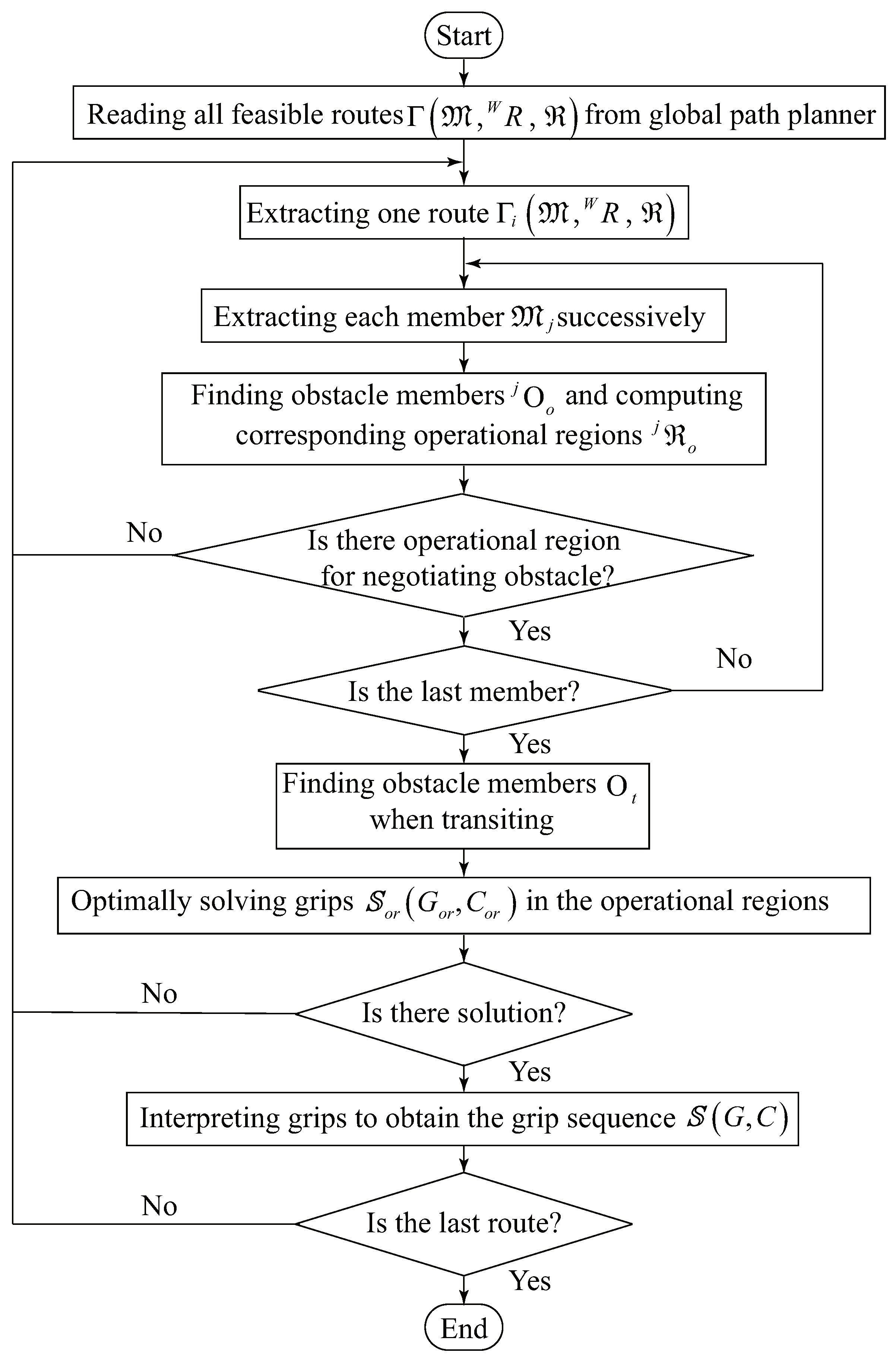
2. Problem Statement

2.1. Global Path Planning and Feasible Routes

In our framework, the crucial point of global path planning is to provide global guidance for the subsequent processes, i.e., grip planning and single-step motion planning. It concentrates on the fast determination of all feasible routes, Γ . The distinguishing merit is that it largely narrows down the searching space to a limited number of members, and thus largely increases the searching efficiency.
As a global guidance for BiCRs, a feasible route, Γ i , should indicate the entire climbing path with the member sequence M , the gripping orientations W R on the members, and the operational regions R t for transitions. Figure 2 shows us an illustration of one feasible route in a scene consisting of 7 members, taken from [27]. In the scene, each member is described in the world frame { W } as
W P = W P 0 + t · W P d i r , 0 t L m e m ,
where W P 0 , W P d i r and L m e m are the reference point, the direction unit vector and the length of the member, respectively. While t is a scale, which can be used to specify the gripping position on the member. For the convenience of expression and understanding, j x is denoted as a grip position on the j-th member from where a transition begins (the takeoff segment) and j y on the same member to where a transition ends (the landing segment). That is to say, j x and j y are also scales the same as t. Based on this notation, the operational regions for transiting from j-th member to (j + 1)-th member are the set of j x and j + 1 y , i.e.,
j x [ j x ̲ , j x ¯ ] j + 1 y [ j + 1 y ̲ , j + 1 y ¯ ] ,
where the boundaries are computed by the transition analyzer during global path planning. We proved that j + 1 y and j x are linear for BiCRs like Climbot with planar configurations in [27]. Therefore, their relationship can be written as
j + 1 y = σ j x + δ ,
where σ and δ are constants. In other words, the gripping points within the operational regions for transitions are one-to-one mapping.

2.2. The Problem of Optimal Collision-Free Grip Planning

From Figure 2, we can see that BiCRs may collide with the truss members during climbing, no matter when it moves forward on a member or transits between two adjacent members. Without loss of generality, the collision-free grip planning problem in a truss environment can be simplified as the model shown in Figure 3. For ease of understanding, we define three categories of operational regions. They are (1) the operational region R i n i t representing the starting point t i n i t and the destination t g o a l , which are given beforehand, (2) the operational region R t for performing transitions between adjacent members, which is output from the global path planner, and (3) the operational region R o for negotiating obstacles when moving on a member. The operational regions for transitions are highlighted with green, while that for negotiating obstacles are with red in Figure 3. Accordingly, the optimal collision-free grip planning problem is to compute R o , then optimally determine grips within R t and R o , and finally arrange grips between R t and R o so that adjacent grips satisfy the robot kinematics.
Figure 4 shows us the flowchart of our proposed optimal collision-free grip planning algorithm. Each feasible route Γ i = { M , W R , R t } is extracted for grip planning successively. For each member M j of Γ i , the operational region j R o for negotiating obstacle members will be computed with a mathematical model (which will be presented in Section 3). After getting the operational regions for negotiating obstacles on all via members, an optimization model is used to determine the grips S o r G o r , C o r within the operational regions. The objective of this optimization model is to achieve the minimum number of climbing steps and the good manipulability of the transition grips. The optimization model also takes the relationship between step length and climbing gaits into account. Finally, a gait interpreter is designed to arrange grips outside of the operational regions, to obtain the entire grip sequence S G , C . Guiding by the output of the grip optimization model, the gait interpreter can ensure a shifting configuration exists for each pair of adjacent grips. This shifting configuration will be the input of single-step motion planning. During the grip planning procedure, the route will be determined to be blocked if solving of the operational region j R o for negotiating obstacles fails or no solution for the grip optimization model.

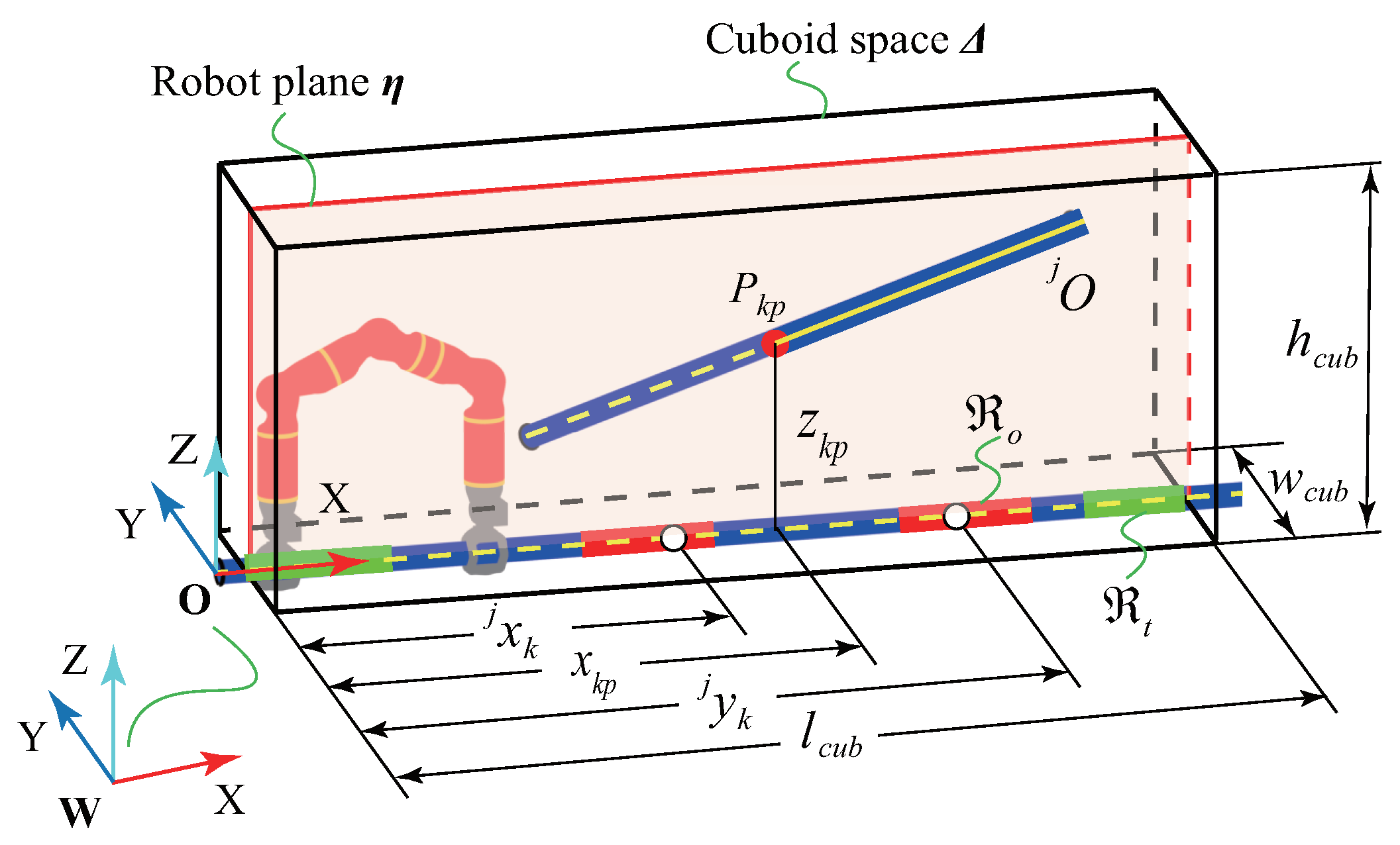
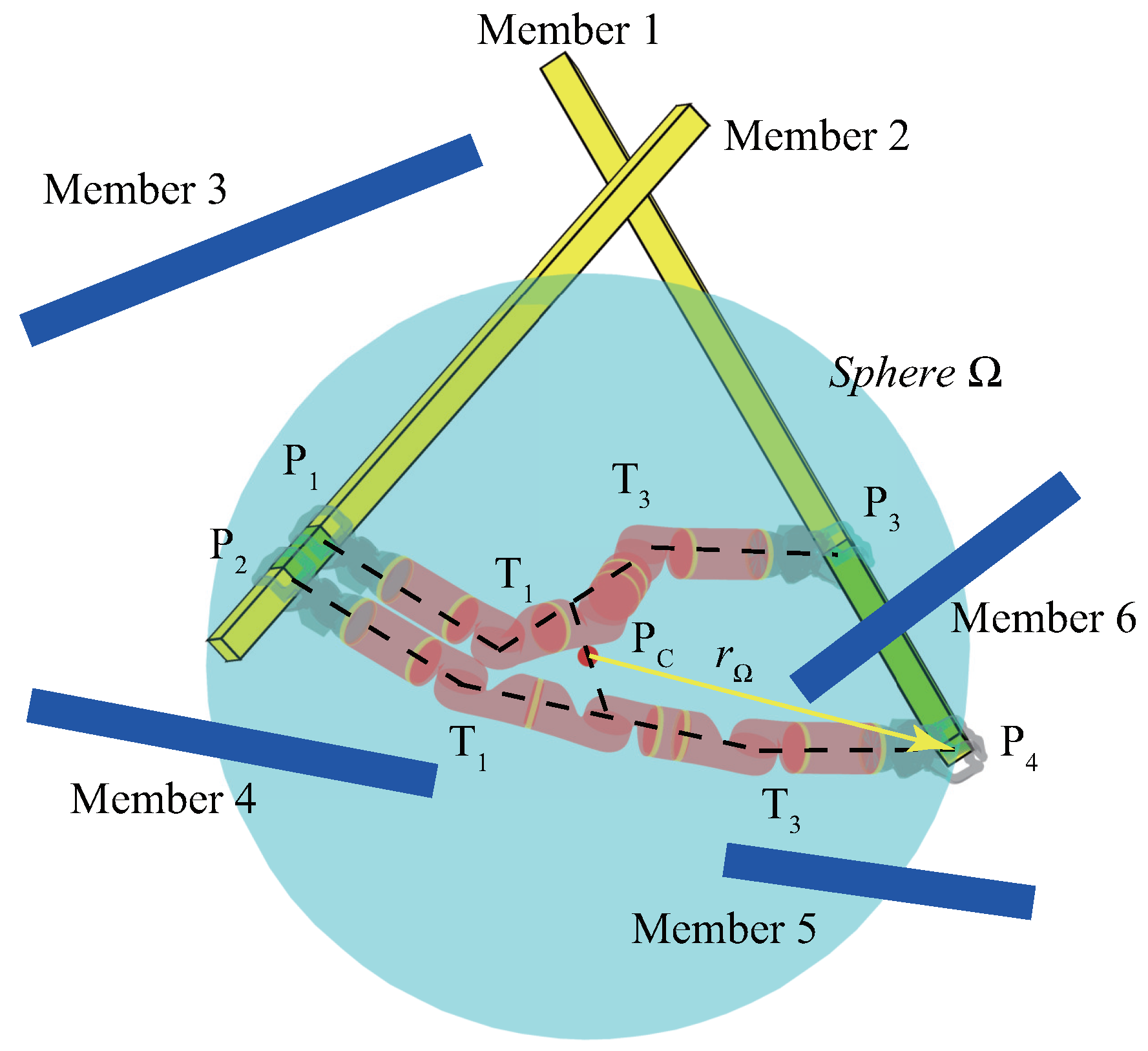
3. Computation of Operational Regions for Negotiating Obstacles

In this section, we study how BiCRs negotiate obstacles to move from the transition landing segment to the next takeoff segment on a specific member.

3.1. The Key Point for Negotiating Obstacles

As mentioned earlier, for the j-th member, the applicable gripping orientation W R j , the transition landing segment [ j y ̲ , j y ¯ ] and next takeoff segment [ j x ̲ , j x ¯ ] are determined by the global path planner. BiCRs with planar configuration can only move within a plane, i.e., the robot plane η as shown in Figure 5, along the via member. Therefore, the possible range of collision can be segmented by a cuboid Δ . Denote l c u b , w c u b and h c u b as the length, width and height of this cuboid, respectively. The dimension of the cuboid can be set as,
l c u b = m a x ( | | j x j y | | ) w c u b = 2 r l i n k + r m e m h m a x = l 2 sin arcsin l s a f e / l 2 + θ m a x / 2 + l 1 + r l i n k + r m e m ,
where r l i n k and r m e m are the radii of the robot links and the truss members; l 1 and l 2 refer to the robot link lengths indicated in Figure 1, while θ m a x is the maximum rotation angle of the T-type joint of the robot; l s a f e is a pre-defined safe distance to facilitate the gripping and grip-releasing operations. In this paper, only the truss members are considered as potential obstacles during climbing. Thus after defining this cuboid, the robot can only collide with those members that intersect the cuboid during the movement from the transition landing segment to the next takeoff segment. Conversely, the potential obstacle members can be extracted out by an intersection check between each member and the cuboid.
Next, we define a Key   Point which plays a key role to determine the reasonable obstacle-negotiating configuration. As shown in Figure 5, the obstacle-negotiating configuration is a state that the robot grips on the j-th member with both grippers, surrounding the obstacle with its body (Figure 6a) or avoiding collision with the obstacle by lowering its body (Figure 6b). The  Key   Point is actually the point that most likely to collide with the robot in the obstacle-negotiating configuration.
Suppose the angle between the obstacle member axis and the robot plane is λ . If λ < λ t h r e s h o l d , where λ t h r e s h o l d is a small angle, the obstacle member is approximately parallel to the robot plane. In this case, the Key   Point is one of the end points of the obstacle member axis, according to the striding-over mode or the creeping mode selected for negotiating obstacles. If λ > λ t h r e s h o l d , where the obstacle member intersects the robot plane, the Key   Point is selected as,
  • the intersection point between the obstacle member axis and η , if this intersection point locates within the cuboid, or
  • the intersection point between the obstacle member axis and the cuboid, if the intersection point between the obstacle member axis and η is outside the cuboid. The Key   Point , in this case, is closest to η .

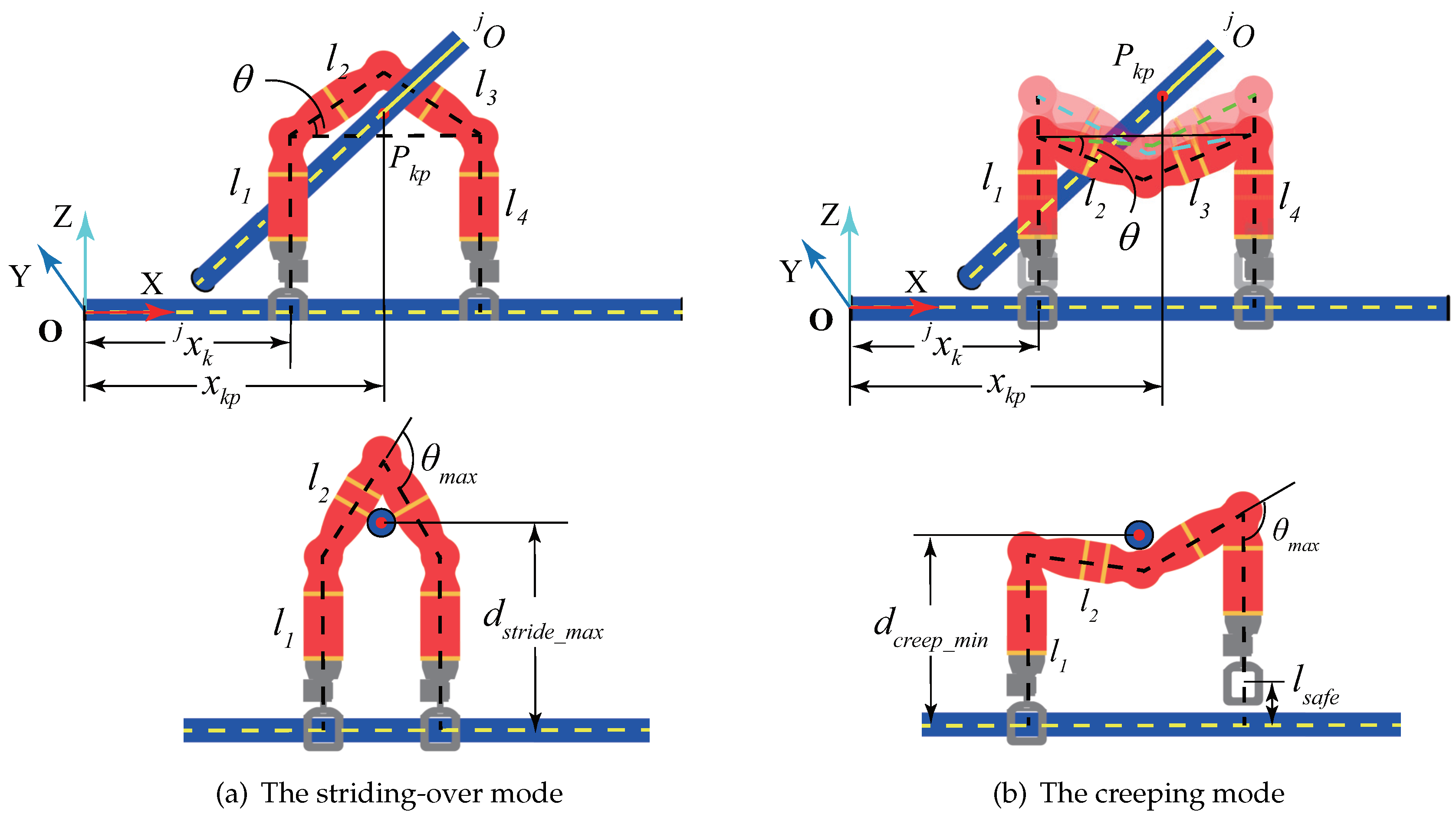
3.2. The Mode to Negotiate Obstacles

Basically, BiCRs have two modes of surmounting obstacles, which are the striding-over mode and the creeping mode, respectively, illustrated with Climbot in Figure 6. Denote d o as the distance between the Key   Point and the gripping member. The maximum distance d s t r i d e ̲ m a x for striding-over and the minimum distance d c r e e p ̲ m i n for creeping, can be calculated with the robot’s parameters. Obviously, the robot can surmount the obstacle member only with the striding-over mode when d o is smaller than d c r e e p ̲ m i n as shown in Figure 6a, and with the creeping mode when d o is larger than d s t r i d e ̲ m a x as shown in Figure 6b. In the case of ( d c r e e p ̲ m i n < d o < d s t r i d e _ m a x ) , the robot can overcome the obstacle with either of these two modes. Further reflecting in the mathematical model (Equation (5)) to compute the operational regions for negotiating obstacles, the applicable mode determines the boundaries of the rotation angle of the T 1 or T 3 joint of the robot.

3.3. The Mathematical Model of Operational Regions for Negotiating Obstacles

Assume n j periods of obstacle crossings are required to move from j y to j x on the j-th Member. For the k-th period of obstacle crossing, referring to Figure 5 and Figure 6, its operational region R o is dependent on two variables, j x k and the rotation angle θ of the T 1 or T 3 joint of the robot. Moreover, the minimum and maximum of j x k are exactly the boundaries of the takeoff segment, while j x k and θ determine the boundaries of the landing segment. Therefore, the following mathematical model is built up to calculate the maximum operational region R o = { f 1 , f 2 , f 3 , f 4 } :
minimize j x k f 1 = j x k maximize j x k f 2 = j x k minimize j x k , θ f 3 = j x k + 2 l 2 cos θ maximize j x k , θ f 4 = j x k + 2 l 2 cos θ subject to : d i r l i n k + r m e m , θ m i n θ θ m a x , x k p 2 l 2 j x k x k p r l i n k r m e m , x k p + r l i n k + r m e m j x k + d g r i p s ,
where d i is the distance between the robot link and the obstacle member; θ m i n θ m a x is the rotation limitation of the T-type joint of the robot; d g r i p s is the distance between two grips distributed in the takeoff and landing segments, respectively. It should be noted that d i in the pre-gripping and gripper-releasing procedures must be also considered.

4. Optimal Collision-Free Grip Planning

In this section, we discuss the optimal determination of grips within each operational region. Thus, hereafter the three categories of operational regions will be treated equally if not specified.

4.1. Objective: Minimum Climbing Steps and Good Manipulability

4.1.1. Minimum Climbing Steps

To form a firm grip, BiCRs must accomplish several procedures, i.e., detecting the target member, adjusting the gripper’s orientation accordingly, and then approaching the member and gripping it. According to our experiments, the grip operation normally consumes two-thirds of the time in each climbing cycle [28,29]. Therefore, minimizing the total number of climbing steps is a promising solution to reduce the time consumption. Suppose n members are involved in the feasible route, where ( n 1 ) periods of transitions are required. The objective function to minimize the total number of climbing steps can be written as:
minimize j x k , j y k j = 1 n k = 1 n j + 1 g ( j x k , j y k ) + 1 ,
where j y k is generally a grip within the landing segment of an operational region, and j x k is another one within the takeoff segment, while g ( j x k , j y k ) is the function calculating the minimum number of steps required to move from j y k to j x k . This function will be discussed in detail in Section 4.2.1. It should be noted that the landing grip j y k + 1 is corresponding to the takeoff grip j x k in a transiting gait.
In Equation (6), one step should be counted for performing transitions or negotiating obstacles. For the last member, a virtual step after reaching the destination (as shown in Figure 2) is added to maintain the consistency of the form.

4.1.2. Good Manipulability

The configurations corresponding to the boundaries of operational regions for transitions always suffer from singularity or joint rotation limitations. So optimal transition grips should keep a distance from their boundaries. To achieve this goal, we construct a potential field, i.e., Equation (7), to adjust the transition grips as close to the midpoint of the corresponding operational regions as possible. Owing to the function characteristics, closer to the midpoint, the value of the function is smaller and the robot has better manipulability when moves nearby the grips.
minimize j x n j + 1 j = 1 n ( j x n j + 1 j x ̲ n j + 1 ) ( j x n j + 1 j x ¯ n j + 1 ) ,
where j x n j + 1 is actually the last grip on the j-th Member. That is to say, in fact, j x n j + 1 is j x in Equation (2).

4.1.3. Combination

To unify the above two objectives in a function, Equations (6) and (7) are normalized. Equation (6) can be rewritten as,
minimize j x k , j y k j = 1 n k = 1 n j + 1 g ( j x k , j y k ) + 1 j N m i n + 1 ,
where j N m i n is the ideal minimum number of climbing steps going through the j-th member without consideration of collision, which is computed as,
j N m i n = minimize g ( j x n j + 1 , j y 1 ) .
Equation (7) can be written as,
minimize j x n j + 1 j = 1 n ( j x n j + 1 j x ̲ n j + 1 ) ( j x n j + 1 j x ¯ n j + 1 ) ( j x ¯ n j + 1 j x ̲ n j + 1 ) 2 / 4 .
For the destination, this component is set to 1 to place the last grip exactly in the destination. Combining Equations (8) and (10) yields the final objective function in Equation (12).

4.2. Constraints

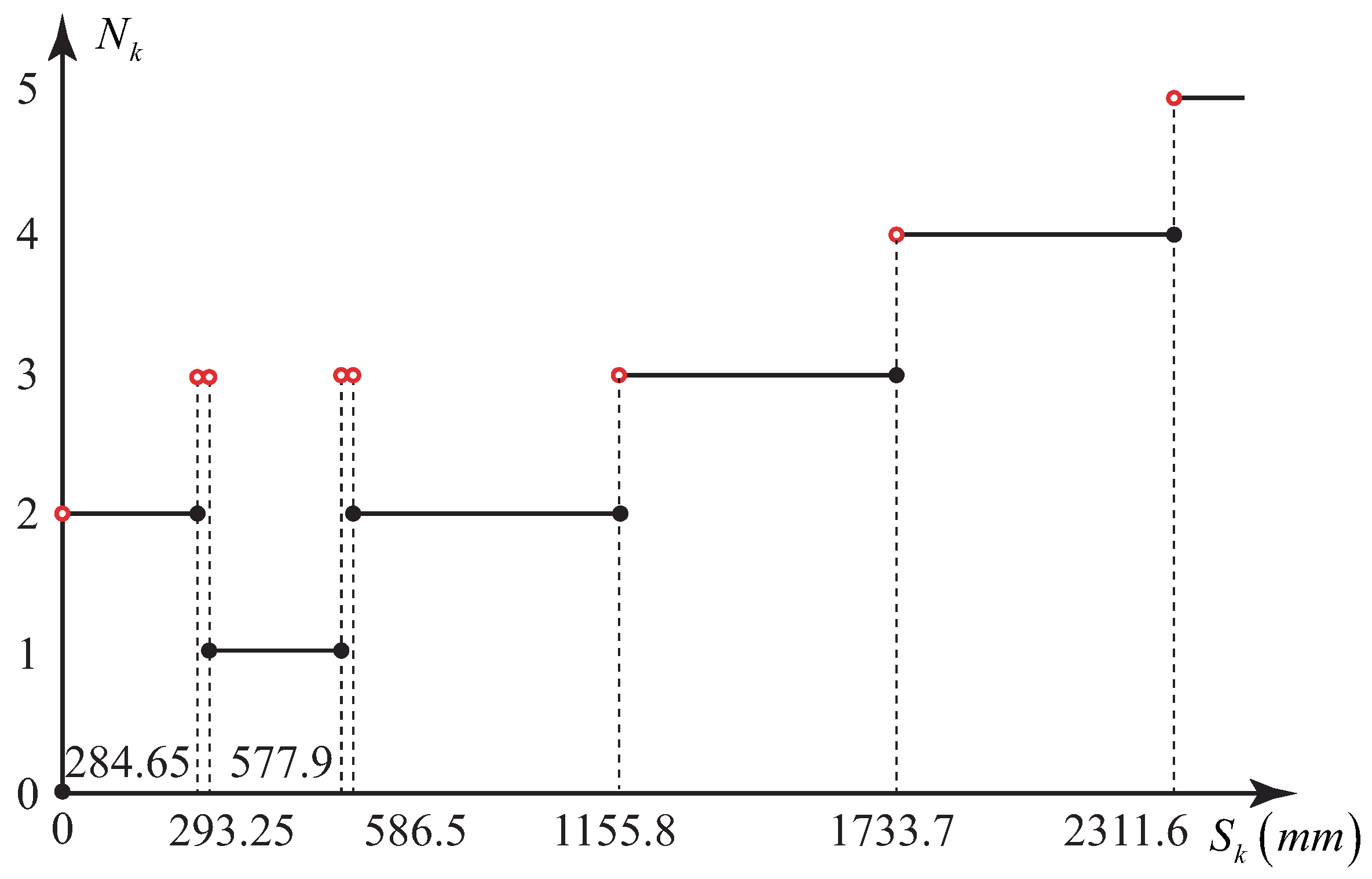
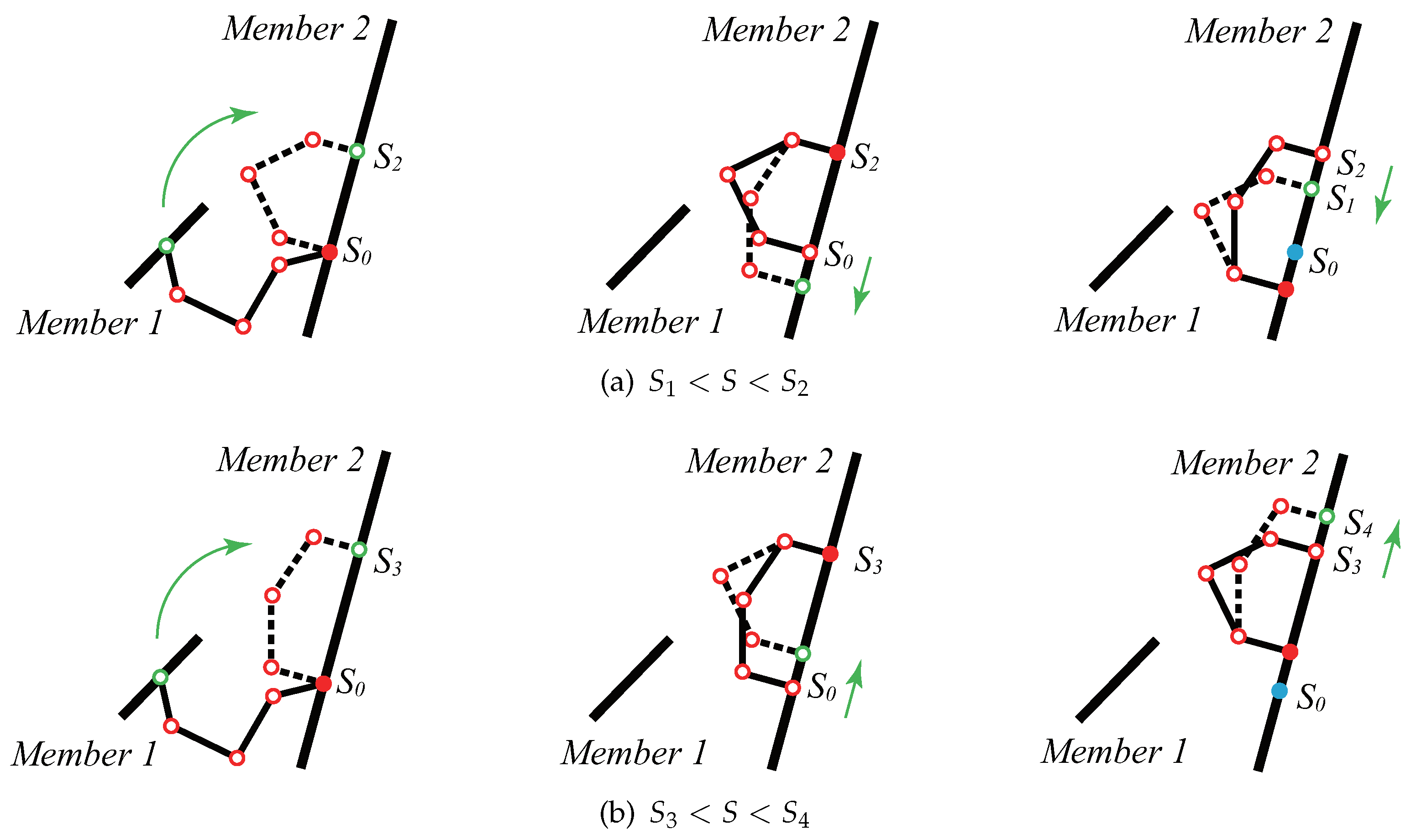
4.2.1. Moving Distance and the Gaits

Benefiting from the bipedal climbing pattern inspired by arboreal primates, BiCRs normally have several climbing gaits. Climbot, for example, has at least three basic gaits, namely the inchworm-like gait, the swinging-around gait, and the flipping-over gait [8]. Each gait has its own characteristics, among which the step length plays a key role in the determination of the required number of climbing steps given a moving distance. Table 1 summarizes the minimum and maximum step lengths of each gait. In the table, the so-called hybrid gait refers to a three-step climbing pattern derived from the basic gaits, as shown in Figure 7.
To go through a given distance, i.e., from a landing segment to a takeoff segment on a certain member, Climbot always can climb with a combination of different gaits. Based on Table 1, we analyze the relationship between the moving distance and the minimum number of required climbing steps as follows.
  • DiMov (direct movement) gait: the moving distance is equal to S 0 . In this case, the landing segment partially (or completely) overlaps with the takeoff segment. Climbot can pass through just with one grip performing two climbing cycles continuously. As a result, the required number of climbing steps in this case is 0.
  • Inch gait: the moving distance is within ( S 0 , S 1 ) . Only the inchworm-like gait is applied to this condition. At least two steps (stretching and shrinking) are required when climbing with the Inch gait.
  • SaFo gait: the moving distance is within ( S 2 , S 3 ) . One step climbing with the swinging-around gait or flipping-over gait meets the distance well.
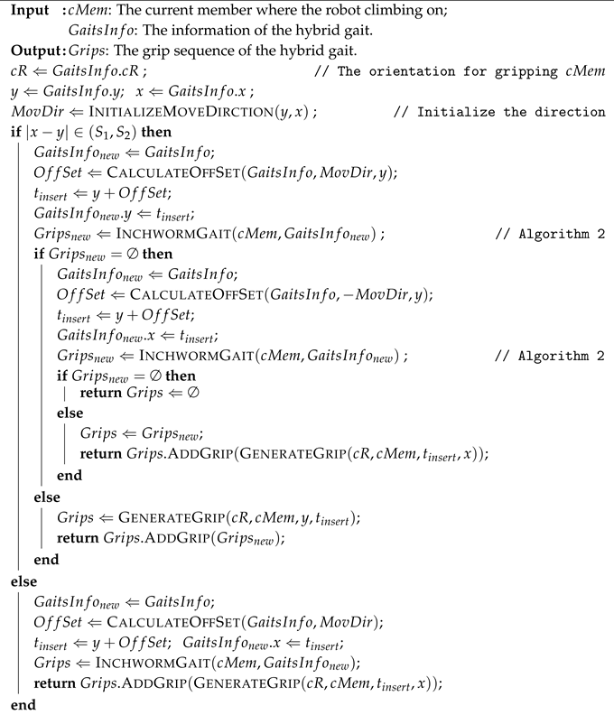
  • Hyb gait: the moving distance is within ( S 1 , S 2 ) or ( S 3 , S 4 ) . Under such circumstances, a mixture of the inchworm-like gait and swinging-around or flipping-over gait should be applied (hybrid gait). Figure 7 illustrates the climbing patterns with Climbot. It moves a step with the swinging-around gait or the flipping-over gait, and then climbs two steps with the inchworm-like gait. Thus, at least three steps are required.
  • SaFo gait: the moving distance is larger than S 4 . The minimum number of climbing steps can be calculated as S k / S 3 , where the symbol represents the ceiling operation. Accordingly, the robot moves with the swinging-around gait or the flipping-over gait.
In summary, the mathematical relationship between the minimum number of climbing steps N k and the corresponding moving distance S k on a member can be expressed as a piecewise function,
g ( j x k , j y k ) = N k = 0 , S k = 0 , 2 , S k ( S 0 S 1 ] , 3 , S k ( S 1 S 2 ) , 1 , S k [ S 2 S 3 ] , 3 , S k ( S 3 S 4 ) , S k / S 3 , S k [ S 4 ) ,
where S k = | j x k j y k | . This piecewise function is plotted in Figure 8. Given the moving distance, the required minimum climbing steps can be computed with Equation (11).

4.2.2. Collision Avoidance during Transitions

Potential collision must be also taken into account when BiCRs perform transitions. As a result, it is necessary to extract the potential obstacle members before solving the grip optimization model, in order to guarantee safe transitions.
Figure 9 shows our strategy to find all the potential obstacles j O t . Supposing BiCRs transit from Member 1 to Member 2, a conservative S p h e r e Ω is constructed based on the operational region R t for transiting. The center P C of S p h e r e Ω coincides with the center point of a set of T 1 and T 3 joint center points corresponding to the boundary configurations. While the radius r Ω of S p h e r e Ω is set as the furthest distance between its center and the gripping points. Thus, this sphere space covers the range where potential collision may happen during transition. Obstacle members are then found out by carrying out intersection checks between the sphere and each truss member. Taking the case in Figure 9 for example, M e m b e r 4 , M e m b e r 5 and M e m b e r 6 will be extracted as the potential obstacles.

4.3. The Optimization Model

Putting all the pieces together gives us the entire optimization model for grip planning, as
minimize j x k , j y k f = j = 1 n k = 1 n j + 1 g ( j x k , j y k ) + 1 j N m i n + 1 + ( j x n j + 1 j x ̲ n j + 1 ) ( j x n j + 1 j x ¯ n j + 1 ) ( j x ¯ n j + 1 j x ̲ n j + 1 ) 2 / 4 subject to : g ( j x k , j y k ) s . t . E q u a t i o n ( 11 ) , j N m i n s . t . E q u a t i o n ( 9 ) , S k = | j x k j y k | , j + 1 y 1 = σ j x n j + 1 + δ , j x k [ j x ̲ k , j x ¯ k ] , j y k [ j y ̲ k , j y ¯ k ] , ( j b k j x k ) ( j x k j c k ) 0 , i f j x k [ j x ̲ k , j b k ] [ j c k , j x ¯ k ] , R j O t = , 1 y 1 = t i n i t , n x n j + 1 = t g o a l ,
where R represents the robot.
Please note that some operational regions have two segments [27], whose boundaries increase in turn. Then the constraint, ( j b k j x k ) ( j x k j c k ) 0 , is added to ensure that j x k is within the valid operational region.

5. Gait Interpreter

After determining the grips within each operational region, it is time to generate grips connecting the operational regions. That is to say, at this time, the grips are generated outside of operational regions. These remaining grips must be arranged in such a proper way that finally any pair of adjacent grips satisfies the robot kinematic constraints. A dedicated gait interpreter is proposed to implement this function in this section.
Algorithm 1 gives out the basic structure of the proposed gait interpreter. The outputs of the optimal collision-free grip planner are G r i p s I n f o , inclusive of S o r G o r , C o r and G a i t I n f o . G a i t s I n f o actually packages the parameters calculated in Section 4.2.1, including the moving distance j S k , number of climbing steps j N k and corresponding g a i t type. These parameters are important reference for the gait interpreter arranging the remaining grips. Therefore, the inputs to the gait interpreter are the truss environment and G r i p s I n f o . During processing, the gait interpreter takes the transition, the obstacle negotiation, or the movement between them as a unit. For each unit, the gait interpreter simply arranges grips by calling an appropriate sub-function, according to the corresponding g a i t type. Sub-functions InchwormGait, HybGait and SaFoGait are designed to generate grips and configurations for the movement between operational regions. While PerformTransition and NegotiateObstacle are designed to pack the transition and obstacle-negotiating grips into the grip sequence.
Algorithm 1: The gait interpreter
Applsci 08 02533 i001
Algorithm 2 is the implementation of the sub-function InchwormGait. InchwormGait takes charge of generating grips for the inchworm-like gait. According to Section 4.2.1, one extra grip t i n s e r t should be inserted for connecting the operational regions. Based on G a i t s I n f o , the function CalculateStepLength is called to calculate the proper step length S t e p L e n with respect to the gripping position y. Then t i n s e r t can be obtained by an offset from the gripping position y. After that, the adjacent grips of y, t i n s e r t and x will be sent for kinematic check. If y and t i n s e r t or t i n s e r t and x do not satisfy the kinematic constraints, t i n s e r t will be updated to the opposite direction on the member. Reflecting on the movement of the robot, it is moving forward or backward to adjust the gripping position. If the kinematic check is passed, the function GenerateGrip is then used to generate G r i p s of an inchworm-like gait. Otherwise, the robot cannot continue to climb along this route.
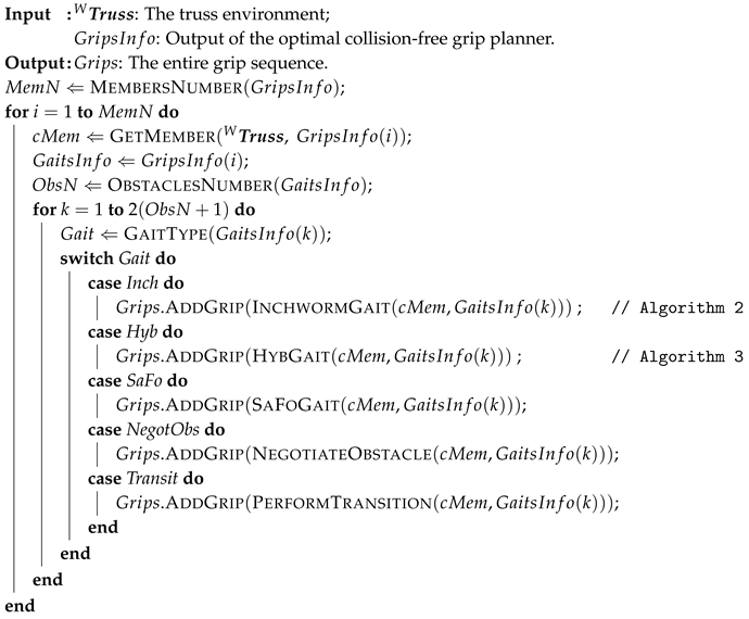
Algorithm 2: InchwormGait: generating grips for the inchworm-like gait
Applsci 08 02533 i002
Algorithm 3 is the implementation of the sub-function HybGait, in charge of generating grips for the hybrid gait. To climb with the hybrid gait, two extra grips need to be inserted. According to Section 4.2.1, every hybrid gait contains an inchworm-like gait. Therefore, one of these two grips will be solved firstly, then the function InchwormGait is called to generate another. The direction I n s D i r of inserting first grip is firstly initialized. Based on the distance between y and x, two different strategies are used by the algorithm. If this distance is in the range of ( S 1 , S 2 ) , an offset O f f s e t is calculated with the function CalculateOffset according to G a i t s I n f o and I n s D i r . Then t i n s e r t can be solved easily. The other grip G r i p s n e w can be obtained by calling the function InchwormGait. If G r i p s n e w is empty, O f f s e t will be updated by changing to another side to insert the grip. Then InchwormGait is called again. If this operation successes, G r i p s between t i n s e r t and x are generated by the function GenerateGrip. Otherwise, the robot cannot reach the destination via this route. If the moving distance is in ( S 3 , S 4 ) , two grips always can be inserted between y and x successfully since there is enough adjustment space.
In the case of S a F o gait, ( S i / S 2 1 ) grips are distributed uniformly between the initial and finished gripping position. Verifications of kinematics and collision avoidance should be applied to each step.
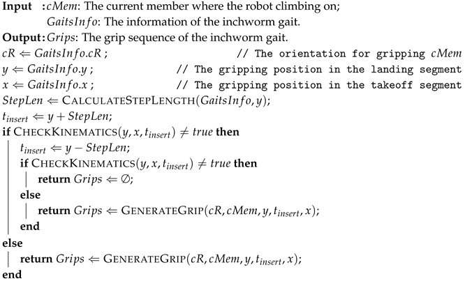
Algorithm 3:HybGait: generating grips for the hybrid gait
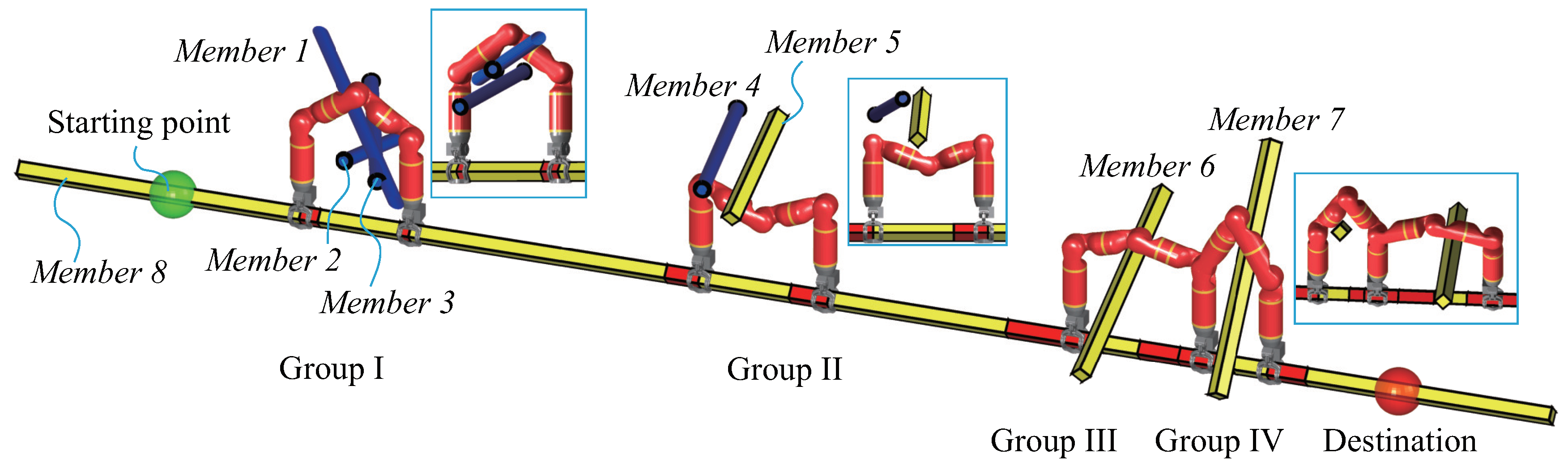
Applsci 08 02533 i003

6. Simulation

To verify the proposed analysis and algorithms, simulations are conducted with Climbot. A simulation environment is developed, and algorithms are implemented on the platform of MATLAB R2015b. All the simulations are launched on a desktop with Intel Core i7-7700K CPU and 16GB RAM, running with the 64-bit operating system Windows 10 Pro. In the simulations, the starting point and the destination are specified manually but arbitrarily, and are highlighted with a green and red sphere, respectively.

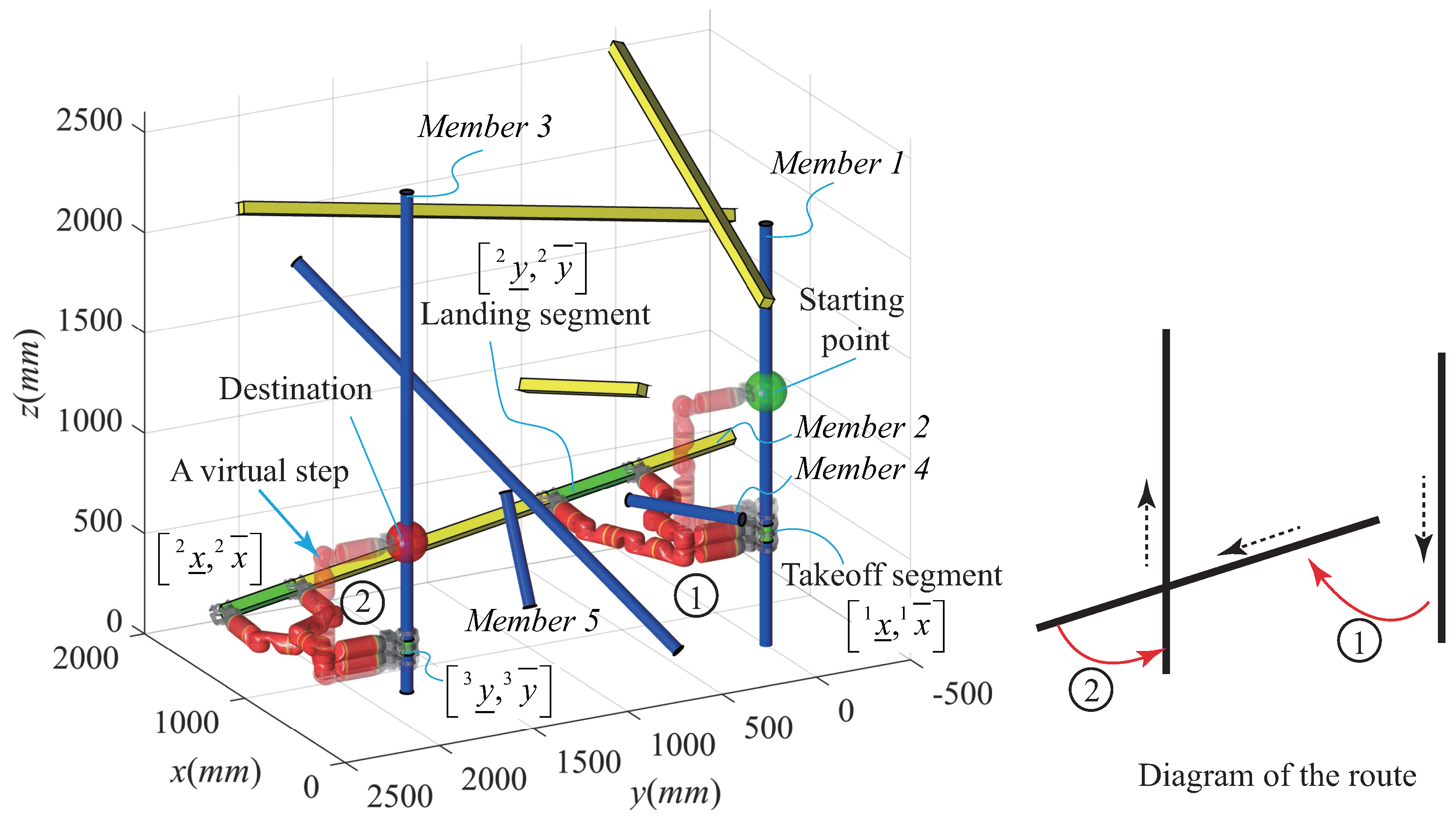
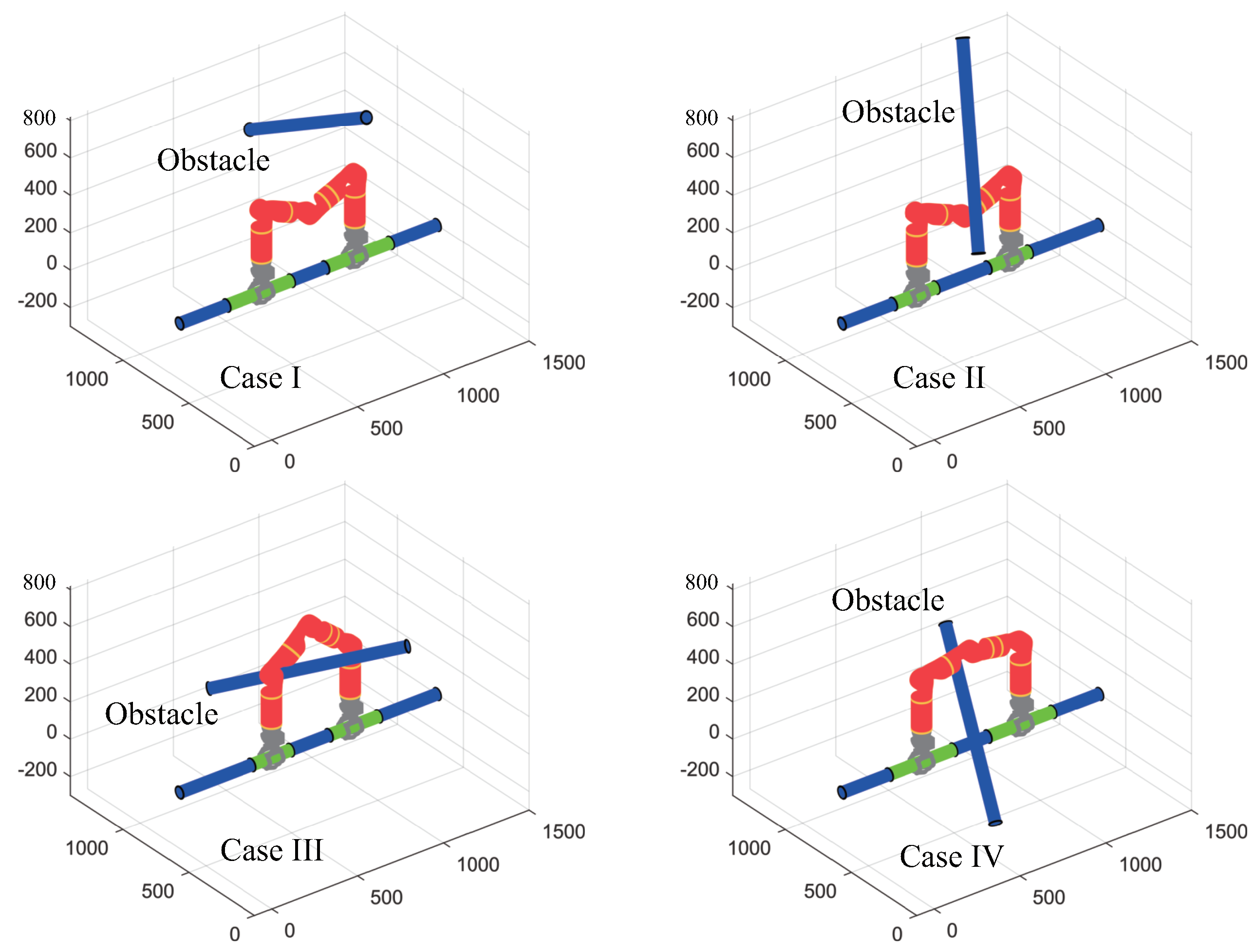
6.1. The Result of Operational Region of Negotiating Obstacle

This part of simulations is to verify the effectiveness and efficiency of the computation of operational regions for negotiating obstacles. In the first scene, Climbot is assumed to move on a member, while another member acts as an obstacle. The pose of the obstacle member is randomly generated. Four snapshots of results are shown in Figure 10. In the figure, the segments highlighted in green are the operational regions obtained for surmounting the obstacle member. A collision-free obstacle-negotiating configuration is provided as an illustration of the effectiveness. We changed the pose of the obstacle member 588 times, 305 of which got operational region. The average time consumed in the computation procedure is 0.13 s, and the maximum one is 0.44 s.
We conduct another simulation with a scene consisting of multiple obstacles, to test the applicability of our model to multi-obstacle cases. The simulation result is shown in Figure 11. In this scene, the robot is requested to move from the left end to the right end on Member 8, overcoming three groups of obstacles successively. In most cases, a group of obstacles, for example { Member 1 , 2 , 3 } or { Member 4 , 5 } in the figure, should be considered at one shot. Because these obstacles must be overcome once and for all. In other cases, for instance, the robot overcome Member 6 and Member 7 with two adjacent steps, the operational region can be simply obtained by an intersection operation of the results for negotiating each individual obstacle. However, how to group the obstacle members reasonably is pending for further study.

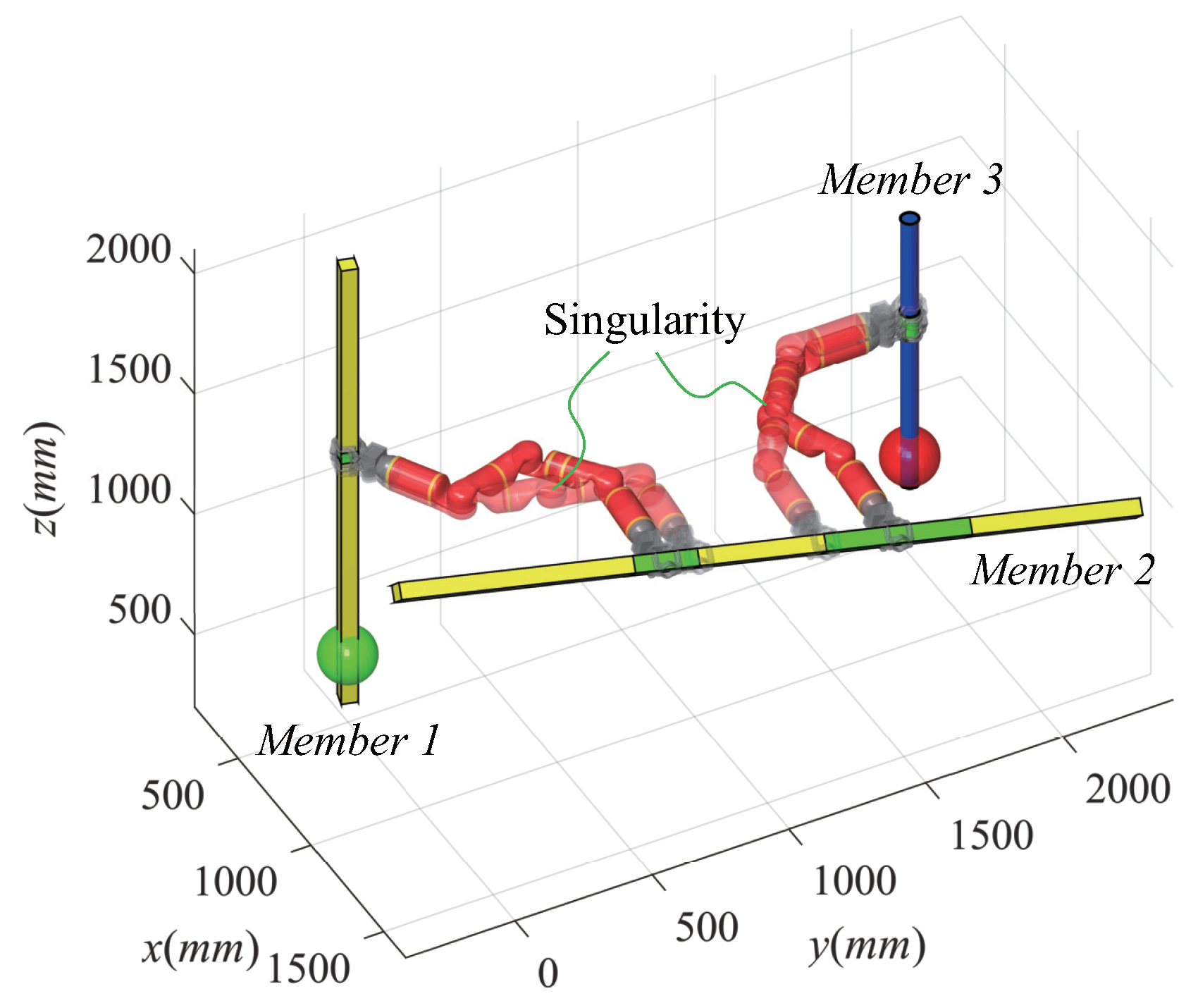
6.2. The Result of Good Manipulability

This part of simulation is conducted to verify the necessity of considering the manipulability of transition grips. In the simple scenario in Figure 12, three members comprise the climbing environment. The robot is requested to start from Member 1, pass Member 2 and finally reach Member 3. The operational regions for transitions, obtained in the global path planning procedure, are highlighted in green. The grip planning results with and without consideration of the grip manipulability are shown in the figure, illustrated with transition configurations. The two slightly transparent configurations, corresponding grips on the boundaries of operational regions, are the results without consideration of the grip manipulability. They are very close to the robot’s singularity (the T 2 joint is close to 0 ). Further in the gripping procedure, it will affect the ability of the robot to adjust its gripper to align with the target member. As a comparison, the other two configurations represent the results considering the grip manipulability but keeping the number of climbing steps the same. From the figure, we can see that the grips are close to the midpoints of the operational regions.

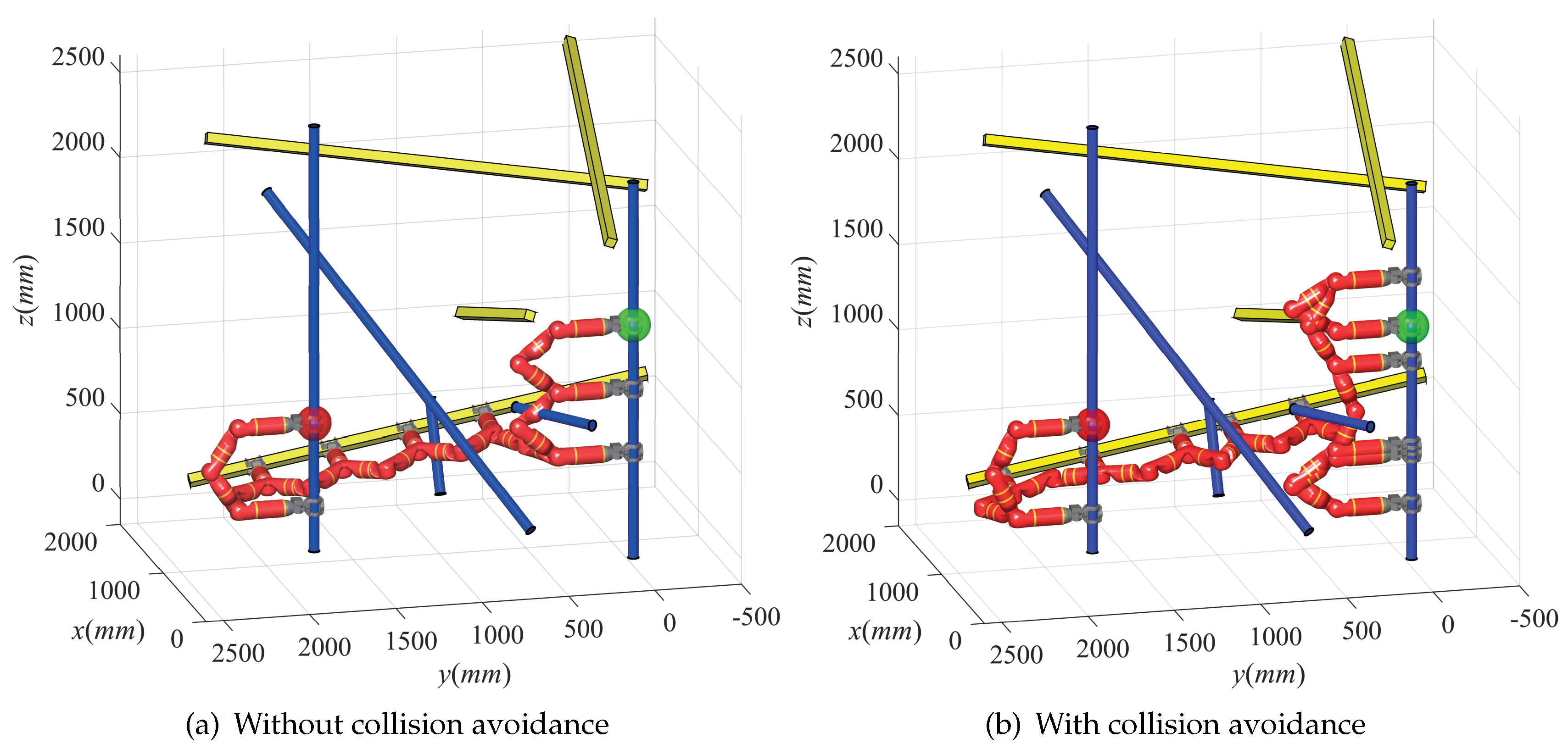
6.3. The Results of Collision-Free Grip Planning

The simulations in this part are conducted to verify the proposed overall grip planning algorithm. The two scenes used in our previous work, consisting of 9 and 25 members, respectively, are again deployed for simulations. Figure 13 and Figure 14 show us the results.
If collision avoidance is not taken into account, we do not need to compute the operational regions for negotiating obstacles prior to grip planning. Only the operational regions for transitions are considered in Equation (12). The optimization objectives are to achieve the minimum number of climbing steps, and good manipulability of transition grips as well. Figure 13a shows us the result planned in this way. Eight climbing steps are required from the starting point to the destination. In the figure, we can see that the robot collides with a member when it moves downwards on the first member. Therefore, in this case, the robot actually cannot execute the climbing movement. If collision avoidance is considered, the planner can generate a collision-free solution, where twelve climbing steps are required. As shown in Figure 13b, four extra adjustment steps are added to the route, to change the grip locations. The robot uses two inchworm-like gaits to adjust the gripping positions in climbing. One time is to get ready to surmount the obstacle member with the creeping mode, while another is to prepare for transition since the operational region is short. The planning procedure considering collision avoidance costs 0.78 s.
Figure 14 shows the comparison of results of grip planning, with and without consideration of collision avoidance, in a complex truss environment with 25 members. According to the outputs of the global path planner, there are three feasible routes in total. On the left column are the results obtained without collision avoidance. As a result, the collision between the robot and the truss members can be found in these sub-figures. The collision can be seen more clearly from the zoom-in views. On the right column are the results with collision avoidance. Collision-free grip sequences are successfully solved for each feasible route. Table 2 summaries the comparison of the results. From the table, we know that obstacle members are detected for each route. The time consumption increases four times if collision avoidance is considered. However, the entire planning procedure is still very quick, which costs approximately 0.65 s only. Moreover, the number of grips increases slightly, as the cost of avoiding collision.

7. Conclusions and Future Work

Biped climbing robots have bright and broad application prospects in the field of performing high-rise truss-related routine tasks. To perform such a task, BiCRs must have the ability to plan their grips prior to climbing.
In this paper, we presented a novel optimal collision-free grip planner for BiCRs generating grip sequence in complex truss environments. The planner essentially consists of three components: (1) a mathematical model for computing the operational regions for surmounting obstacles; (2) a grip placement optimizer for determining the grips within operational regions; and (3) a gait interpreter for generating grips between adjacent operational regions. The idea behind this novel scheme is to use the priority to determine the grips at key places, i.e., operational regions for surmounting obstacles and that for performing transitions, then move to other places. Because normally there is less room to choose and adjust grips for these key places. Simulation results verified that the planner was able to plan approximately 30 grips within 0.65 s, taking collision avoidance, grip manipulability and number of climbing steps into account. However, the current planner only considers the forward and backward movement on a member, which limits the applicable objects as BiCRs with, or less than, five degrees of freedom. In addition, the total time consumed in grip planning is related to the initial values for optimization.
In the near future, we will study the optimal climbing gait type and the collision-free motion for the robot shifting between adjacent grips. Extensive climbing experiments on various trusses will be conducted to further verify our planning algorithms.

Author Contributions

S.G. and H.Z. (Haifei Zhu) co-organized the work, conceived and designed the planner and performed the simulation work. S.G. wrote the manuscript. H.L. and Y.G. co-worked to prepare the final manuscript. Y.G. and H.Z. (Hong Zhang) co-supervised the research.

Funding

This research was funded in part by the National Natural Science Foundation of China (Grant Nos. 51605096, 51705086), the Frontier and Key Technology Innovation Special Funds of Guangdong Province (Grant Nos. 2015B090922003, 2017B050506008), the Program of Foshan Innovation Team of Science and Technology (Grant No. 2015IT100072) and the Open Funds of Beijing Advanced Innovation Centre for Intelligent Robots and Systems (Grant No. 2016IRS16).

Conflicts of Interest

The authors declare no conflict of interest.

Nomenclature

Γ set of all feasible routes
Γ i i-th feasible route, Γ i = M , W R , R t
M member sequence along the route
M j j-th member
R operational region R = { R o , R t , R i n i t } , each inclusive of the takeoff segement and
the landing segement
R t operational region for transiting between adjacent members
R o operational region for negotiating obstacle members
R i n i t operational region representing starting point and destination
W R set of gripping orientations corresponding to member sequence M
W R j gripping orientation on the j-th member
W P 0 , W P d i r , L m e m , r m e m reference point, direction unit vector, length and radius of the j-th member
ta scale to specify the gripping position on the j-th member
W Truss truss environment
j x k k-th gripping position in the takeoff segment [ j x ̲ k , i x ¯ k ] on the j-th member
j y k k-th gripping position in the landing segment [ j y ̲ k , i y ¯ k ] on the j-th member
j O obstacles when moving on the j-th member
S o r G o r , C o r grips in the operational regions
G o r a grip in the operational region, inclusive of gripping position and orientation
C o r a configuration corresponding to G o r
S G , C entire grip sequence
P k p key point for negotiating an obstacle member, P k p = [ x k p , y k p , z k p ]
η robot plane
Δ the cuboid space where collision may happen, for moving on a member
Ω the sphere space where collision may happen, for transiting
l c u b , w c u b , h c u b length, width and height of the cuboid space
l s a f e a pre-defined safe distance to facilitate the gripping and grip-releasing operations
j N m i n minimum number of climbing steps when passing the j-th member
j N k minimum number of climbing steps from the k-th landing segment to the (k + 1)-th
takeoff segment
S 0 , S 1 minimum and maximum step lengths of the inchworm-like gait
S 2 , S 3 minimum and maximum step lengths of the flipping-over gait and
swinging-around gait
S 4 maximum step length of the hybrid gait
R robot

References

  1. Xu, Y.; Brown, B.; Aoki, S.; Kanade, T. Mobility and Manipulation of a Light-weight Space Robot. In Proceedings of the IEEE/RSJ International Conference on Intelligent Robots and Systems, Munich, Germany, 12–16 September 1994; pp. 11–19. [Google Scholar]
  2. Balaguer, C.; Gimenez, A.; Pastor, J.M.; Padron, V.M.; Abderrahim, M. A Climbing Autonomous Robot for Inspection Applications in 3D Complex Environments. Robotica 2000, 18, 287–297. [Google Scholar] [CrossRef]
  3. Detweiler, C.; Vona, M.; Yoon, Y.; Yun, S.K.; Rus, D. Self-assembling Mobile Linkages. IEEE Robot. Autom. Mag. 2007, 14, 45–55. [Google Scholar] [CrossRef]
  4. Tavakoli, M.; Marjovi, A.; Marques, L.; Almeida, A.T.D. 3DCLIMBER: A Climbing Robot for Inspection of 3D Human Made Structures. In Proceedings of the IEEE/RSJ International Conference on Intelligent Robots and Systems, Nice, France, 22–26 September 2008; pp. 4130–4135. [Google Scholar]
  5. Tavakoli, M.; Marques, L. 3DCLIMBER: Climbing and Manipulation over 3D Structures. Mechatronics 2011, 21, 48–62. [Google Scholar] [CrossRef]
  6. Tavakoli, M.; Zakerzadeh, M.R.; Vossoughi, G.; Bagheri, S. A Hybrid Pole Climbing and Manipulating Robot with Minimum DOFs for Construction and Service Applications. Ind. Robot. Int. J. 2005, 32, 171–178. [Google Scholar] [CrossRef]
  7. Lam, T.L.; Xu, Y. A Flexible Tree Climbing Robot: Treebot—Design and Implementation. In Proceedings of the IEEE International Conference on Robotics and Automation, Shanghai, China, 9–13 May 2011; pp. 5849–5854. [Google Scholar]
  8. Guan, Y.; Jiang, L.; Zhang, X.; Zhang, H. Climbing Gaits of a Modular Biped Climbing Robot. In Proceedings of the IEEE/ASME International Conference on Advanced Intelligent Mechatronics, Singapore, 14–17 July 2009; pp. 532–537. [Google Scholar]
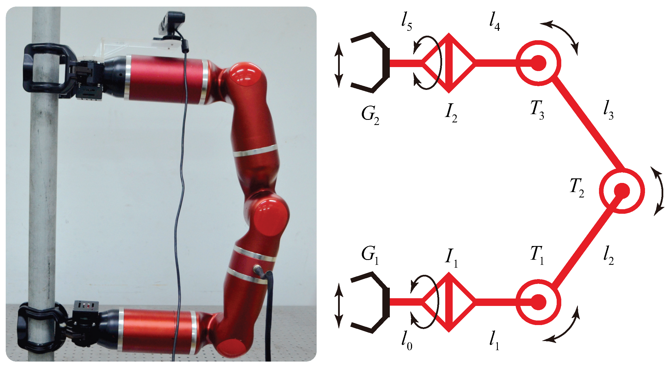
  9. Guan, Y.; Jiang, L.; Zhu, H.; Wu, W.; Zhou, X.; Zhang, H.; Zhang, X. Climbot: A Bio-inspired Modular Biped Climbing Robot—System Development, Climbing Gaits, and Experiments. J. Mech. Robot. 2016, 8, 021026. [Google Scholar] [CrossRef]
  10. Chen, S.; Zhu, H.; Guan, Y.; Wu, P. Collision-free Single-step Motion Planning of Biped Pole-climbing Robots in Spatial Trusses. In Proceedings of the IEEE International Conference on Robotics and Biomimetics, Shenzhen, China, 12–14 December 2013; pp. 280–285. [Google Scholar]
  11. Chen, W.; Gu, S.; Zhu, L.; Zhang, H.; Zhu, H.; Guan, Y. Representation of Truss-style Structures for Autonomous Climbing of Biped Pole-climbing Robots. Robot. Auton. Syst. 2018, 101, 126–137. [Google Scholar] [CrossRef]
  12. Kuffner, J.; Nishiwaki, K.; Kagami, S.; Inaba, M. Footstep Planning among Obstacles for Biped Robots. In Proceedings of the IEEE/RSJ International Conference on Intelligent Robots and Systems, Maui, HI, USA, 29 October–3 November 2001; pp. 500–505. [Google Scholar]
  13. Kuffner, J.; Nishiwaki, K.; Kagami, S.; Inaba, M.; Inoue, H. Motion Planning for Humanoid Robots. Auton. Robot. 2003, 12, 692–698. [Google Scholar]
  14. Chestnutt, J.; Lau, M.; Cheung, G.; Kuffner, J.; Hodgins, J.; Kanade, T. Footstep Planning for the Honda ASIMO Humanoid. In Proceedings of the IEEE International Conference on Robotics and Automation, Orlando, FL, USA, 15–19 May 2006; pp. 629–634. [Google Scholar]
  15. Chestnutt, J.; Kuffner, J.; Nishiwaki, K.; Kagami, S. Planning Biped Navigation Strategies in Complex Environments. In Proceedings of the IEEE International Conference on Humanoid Robotics, Karlsruhe, Germany, 29–30 September 2003. [Google Scholar]
  16. Chestnutt, J.; Kuffner, J. A Tiered Planning Strategy for Biped Navigation. In Proceedings of the IEEE/RSJ International Conference on Humanoid Robots, Santa Monica, CA, USA, 10–12 November 2004; pp. 422–436. [Google Scholar]
  17. Ayaz, Y.; Munawar, K.; Malik, M.B.; Konno, A.; Uchiyama, M. Human-Like Approach to Footstep Planning Among Obstacles for Humanoid Robots. In Proceedings of the IEEE/RSJ International Conference on Intelligent Robots and Systems, San Diego, CA, USA, 29 October– 2 November 2007; pp. 5490–5495. [Google Scholar]
  18. Ayaz, Y.; Owa, T.; Tsujita, T.; Konno, A. Footstep planning for Humanoid Robots among Obstacles of Various Types. In Proceedings of the IEEE International Conference on Humanoid Robots, Paris, France, 7–10 December 2009; pp. 361–366. [Google Scholar]
  19. Deits, R.; Tedrake, R. Footstep Planning on Uneven Terrain with Mixed-integer Convex Optimization. In Proceedings of the IEEE/RSJ International Conference on Humanoid Robots, Madrid, Spain, 18–20 November 2014; pp. 279–286. [Google Scholar]
  20. Kuindersma, S.; Deits, R.; Fallon, M.; Valenzuela, A.; Dai, H.; Permenter, F.; Koolen, T.; Marion, P.; Tedrake, R. Optimization-based Locomotion Planning, Estimation, and Control Design for the ATLAS Humanoid Robot. Auton. Robot. 2016, 40, 429–455. [Google Scholar] [CrossRef]
  21. Guan, Y.; Yokoi, K.; Tanie, K. Feasibility: Can Humanoid Robots Overcome Given Obstacles? In Proceedings of the IEEE International Conference on Robotics and Automation, Orlando, FL, USA, 15–19 May 2006; pp. 1054–1059. [Google Scholar]
  22. Guan, Y.; Neo, E.S.; Yokoi, K.; Tanie, K. Stepping over Obstacles with Humanoid Robots. IEEE Trans. Robot. 2006, 22, 958–973. [Google Scholar] [CrossRef]
  23. Balaguer, C.; Padron, V.M.; Gimenez, A.; Pastor, J.M.; Abderrahim, M. Path Planning Strategy of Autonomous Climbing Robot for Inspection Applications in Construction. In Proceedings of the International Symposium on Automation and Robotics in Construction, Madrid, Spain, 22–24 September 1999. [Google Scholar]
  24. Detweiler, C.; Vona, M.; Kotay, K.; Rus, D. Hierarchical Control for Self-assembling Mobile Trusses with Passive and Active Links. In Proceedings of the IEEE International Conference on Robotics and Automation, Orlando, FL, USA, 15–19 May 2006; pp. 1483–1490. [Google Scholar]
  25. Chung, W.K.; Xu, Y. Minimum energy demand locomotion on space station. J. Robot. 2013, 2013, 723535. [Google Scholar] [CrossRef]
  26. Zhu, H.; Guan, Y.; Su, M.; Cai, C. Evaluation of Graspable Region and Selection of Footholds for Biped Pole-climbing Robots. In Proceedings of the IEEE International Conference on Robotics and Biomimetics, Bali, Indonesia, 5–10 December 2014; pp. 1757–1762. [Google Scholar]
  27. Zhu, H.; Gu, S.; He, L.; Guan, Y.; Zhang, H. Transition Analysis and Its Application to Global Path Determination for a Biped Climbing Robot. Appl. Sci. 2018, 8, 122. [Google Scholar] [CrossRef]
  28. Xiao, Z.; Wu, W.; Wu, J.; Zhu, H. Gripper Self-alignment for Autonomous Pole-grasping with a Biped Climbing Robot. In Proceedings of the IEEE International Conference on Robotics and Biomimetics, Guangzhou, China, 11–14 December 2012; pp. 181–186. [Google Scholar]
  29. Gu, S.; Su, M.; Zhu, H.; Guan, Y.; Rojas, J.; Zhang, H. Efficient Pole Detection and Grasping for Autonomous Biped Climbing Robots. In Proceedings of the IEEE International Conference on Robotics and Biomimetics, Macau, China, 5–8 December 2017; pp. 246–251. [Google Scholar]
Figure 1. The 5-DoF Climbot and its kinematic diagram.
Applsci 08 02533 g001
Figure 2. An illustration of a feasible route. Green and red spheres in the figure stand for the initial position and the destination, respectively. Nearby numbers indicate the sequence of transitions to be performed along the route.
Applsci 08 02533 g002
Figure 3. A general model of collision-free grip planning for BiCRs.
Applsci 08 02533 g003
Figure 4. The flowchart of collision-free grip planning.
Applsci 08 02533 g004
Figure 5. The definition of collision avoidance space and Key   Point .
Applsci 08 02533 g005
Figure 6. Negotiating obstacles with the striding-over mode and the creeping mode.
Applsci 08 02533 g006
Figure 7. The three-step hybrid gait. The solid lines represent the current configuration, while the dashed ones stand for the following configuration one step forward.
Applsci 08 02533 g007
Figure 8. The relationship between moving distance (on a member) and minimum climbing steps.
Applsci 08 02533 g008
Figure 9. The method to extract potential obstacles when transiting between adjacent members.
Applsci 08 02533 g009
Figure 10. The results of computing operational regions for negotiating an obstacle in various pose.
Applsci 08 02533 g010
Figure 11. The results of computing operational regions for negotiating multiple obstacles.
Applsci 08 02533 g011
Figure 12. The comparison of determination of transition grips with and without consideration of the grip manipulability.
Applsci 08 02533 g012
Figure 13. Comparison of results of grip planning with and without consideration of collision avoidance in a scene of 9 members.
Applsci 08 02533 g013
Figure 14. Comparison of results of grip planning with and without consideration of collision avoidance in a scene of 25 members.
Applsci 08 02533 g014
Table 1. Minimum and maximum step lengths with different gaits.
GaitsStep Lengths
MinimumMaximum
Inchworm-like gait S 0 = 0 S 1 = S 3 S 2
Hybrid gait S 1 S 2 = 2 l 2 ( 1 c o s ( θ m a x / 2 ) )
Swinging-around or Flipping-over gait S 2 S 3 = ( 2 l 2 ) 2 l s a f e 2
Hybrid gait S 3 S 4 = 2 l 2
Table 2. Comparison of results of grip planning with and without the consideration of collision avoidance.
ItemsCollision AvoidanceRoute IRoute IIRoute III
Number of via members\667
Number of detected obstacle memberswithout\\\
with1379
Number of gripswithout212829
with283134
Time consumption (s)without0.120.110.13
with0.650.620.63

