Article

Performance Analysis and Improvement of Optical Camera Communication

Department of Electronics Engineering, Kookmin University, Seoul 02707, Korea
*
Author to whom correspondence should be addressed.
Appl. Sci. 2018, 8(12), 2527; https://doi.org/10.3390/app8122527
Submission received: 2 November 2018 / Revised: 3 December 2018 / Accepted: 3 December 2018 / Published: 6 December 2018

Abstract

:
Optical camera communication (OCC) is a technology in which a camera image sensor is employed to receive data bits sent from a light source. OCC has attracted a lot of research interest in the area of mobile optical wireless communication due to the popularity of smartphones with embedded cameras. Moreover, OCC offers high-performance characteristics, including an excellent signal-to-interference-plus-noise ratio (SINR), high security, low interference, and high stability with respect to varying communication distances. Despite these advantages, OCC suffers from several limitations, the primary of which is the low data rate. In this paper, we provide a comprehensive analysis of the parameters that influence the OCC performance. These parameters include the camera sampling rate, the exposure time, the focal length, the pixel edge length, the transmitter configurations, and the optical flickering rate. In particular, the focus is on enhancing the data rate, SINR, and communication distance, which are the principal factors determining the quality of service experienced by a user. The paper also provides a short survey of modulation schemes used in OCC on the basis of the achieved data rate, communication distance, and possible application scenarios. A theoretical analysis of user satisfaction using OCC is also rendered. Furthermore, we present the simulation results demonstrating OCC performance with respect to variations in the parameters mentioned above, which include the outage probability analysis for OCC.

1. Introduction

Optical wireless communication (OWC) has recently become a congruent complement of radio-frequency (RF) technologies due to its vast unregulated spectrum, as well as the dense formation of lighting infrastructures in both indoor and outdoor scenarios [1]. It has introduced a new venture for the Internet of Things (IoT) by increasing connectivity options. The optical spectrum is entirely cost-free and is a significant option to assist RF in handling the massive data traffic envisaged for the future.
Optical camera communication (OCC) is a subsystem of OWC that uses visible or infrared light to communicate with a camera sensor [1]. Complementary metal-oxide-semiconductor (CMOS) cameras integrated into smartphones or mobile robots have become very common in recent years, making OCC immensely promising. Current commercial light-emitting diodes (LEDs) offer low costs, a low power consumption, high efficiency, and are established almost everywhere. Exploiting cameras to receive data sent from LED transmitters adds a significant dimension in the area of OWC systems. Accordingly, IEEE has developed a task group regarding OCC, called IEEE 802.15.7m [2]. OCC is a directional technology that provides the users with a high level of security. Moreover, due to the nature of camera pixels, an OCC system is less affected by interference than any other OWC technologies. These characteristics open up possibilities for the system’s usability in a variety of applications, including vehicle-to-vehicle and vehicle-to-infrastructure (V2X) communications [3,4] digital signage, augmented reality (AR), and location-based services (LBS) [5,6,7].
However, several challenges have been observed while communicating using image sensors. First, cameras cannot detect LEDs blinking at a high frequency [8]. Second, very low frequencies lead to flickering observed by the human eyes, which is prohibited. Third, conventional cameras offer low sampling rates, resulting in a low-rate data reception. Fourth, synchronization between the LED modulation frequency and the camera shutter speed is also an important challenge for OCC. Without proper synchronization, the bit-error rate (BER) increases. Although OCC is very stable in terms of changing the communication distance, the limited angle-of-view (AOV) leads to the system not exploiting the full LED coverage area. Moreover, an image should appear in several pixels to decode the information sent from the LED. Therefore, the fifth reason that significantly affects OCC performance accounts to the pixel edge length.
Different methods can be employed to improve OCC performance. Deep-learning-based algorithms can be utilized to increase the data rate and communication distance. A convolutional neural network was proposed in [2] in conjunction with OCC to receive data in outdoor environments. Communication in these scenarios is affected by sunlight and bad weather conditions (fog, rain, or snow). Computer vision techniques can also be utilized for accurate LED pattern classification and recognition to increase the signal-to-interference-plus-noise ratio (SINR), communication distance, and data rate for OCC. In recent times, red/green/blue (RGB) LEDs are used in OCC to improve the performance. Deep learning is a significant option to design the transceiver for RGB-LED-based communications [9]; however, this technique faces some limitations, such as its computation expensiveness and configuration complexities.
Researchers have been investigating how to enhance the OCC performance for years. Enhancement of the signal performance of mobile-phone-based OCC using histogram equalization was reported in Reference [10]. An improved decoding method for OCC for vehicular applications using high-speed cameras was presented in Reference [11]. Recently, researchers have been exploring how to increase the maximum communication distance and data rate by introducing new modulation schemes. In Reference [12], a combination of modulation schemes has been proposed to achieve an improved data rate. On the other hand, RGB LEDs are utilized to enhance the communication distance for OCC [13].
Nonetheless, to the best of our knowledge, no researchers have briefly examined the OCC performance emphasizing on the effects of the LED and camera parameters. In this study, we provide a comprehensive discussion of these parameters that affect OCC performance. We emphasize cameras using the rolling shutter technique, as these types are very popular, cost-effective, and widely available. Our main contributions in this paper are summarized as follows:
  • We briefly explore the role of LED and camera parameters in determining OCC performance. Variations in these parameters lead to our insights on variations in the OCC performance. We focus on key issues related to the quality of service, including data-rate enhancement, SINR improvement, increasing the communication distance, and decreasing BER.
  • We present a channel model for OCC based on Lambertian radiant intensity [14]. The channel model is also used as the basis for our analysis of pixel SINR.
  • We provide a theoretical representation of OCC users’ satisfaction.
  • We conducted a short survey of existing modulation schemes and categorize them according to communication distance and data-rate characteristics in order to enable us to select the appropriate scheme for a specific application.
  • We present simulation results (including the outage probability analysis for OCC) that demonstrate which values of the parameters are optimal to achieve the required OCC output for performance improvement.
The remainder of this paper is organized as follows. Section 2 provides an overview of the OCC data decoding principle and system parameters that include the OCC channel model and representation of pixel SINR. In Section 3, we outline the analysis of parameters that determine the performance of an OCC system. Section 4 presents a short survey of existing techniques to modulate the OCC transmitter. An analysis of the OCC user satisfaction is presented in Section 5. Simulation results involving OCC performance variations regarding changing LED and camera parameters are evaluated in Section 6. Finally, a brief summary of our work and possible future research are provided in Section 7.

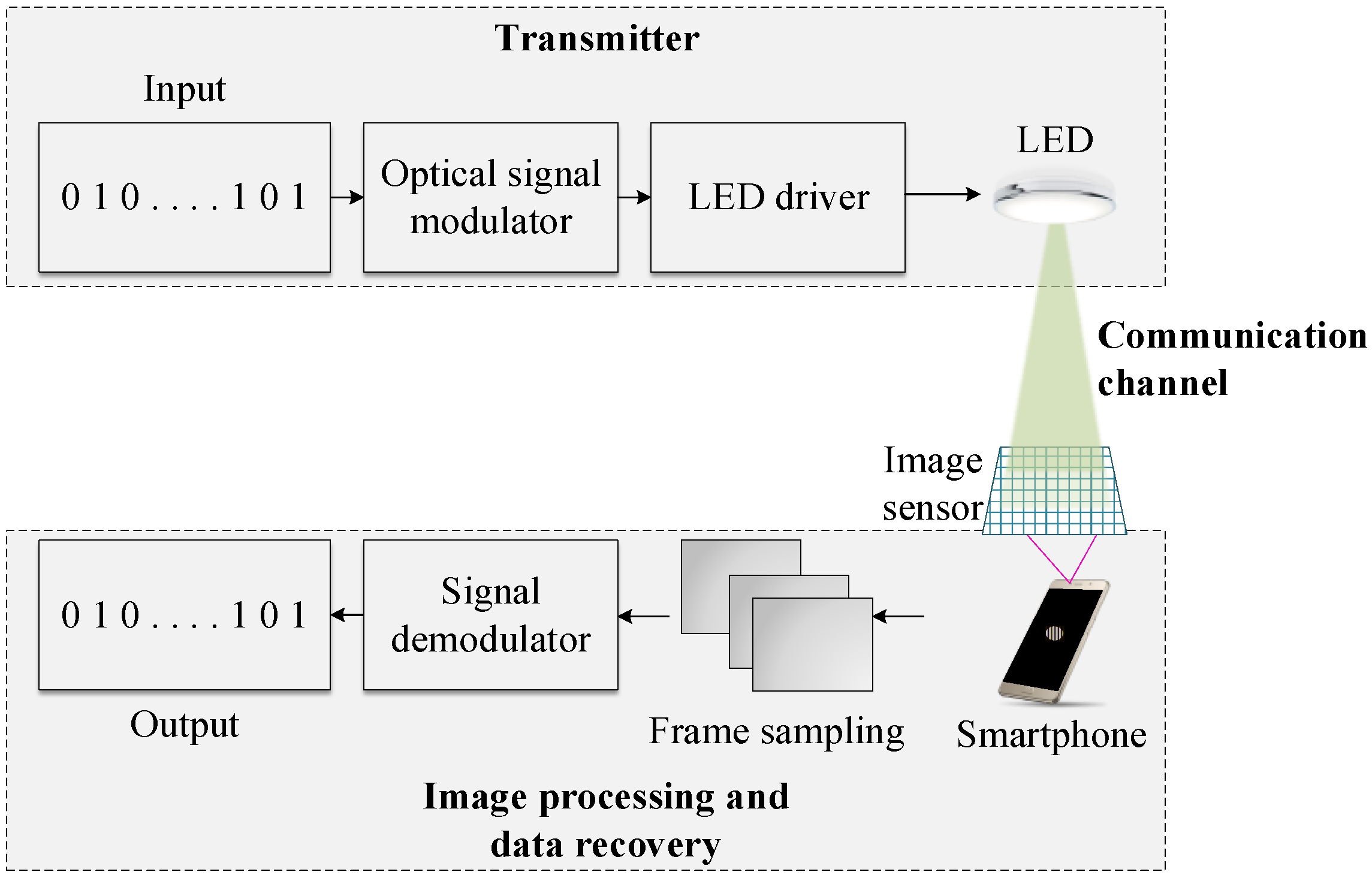
2. OCC System Overview

Figure 1 shows a generalized block diagram of the OCC system. The data is modulated using a modulation technique, and an LED driver is used to activate the LED. The projected image of the LED is then processed to demodulate the data bits. The optical channel characteristics of OCC are similar to those of other OWC technologies except that the system can achieve higher SINRs as it is less susceptible to interferences.

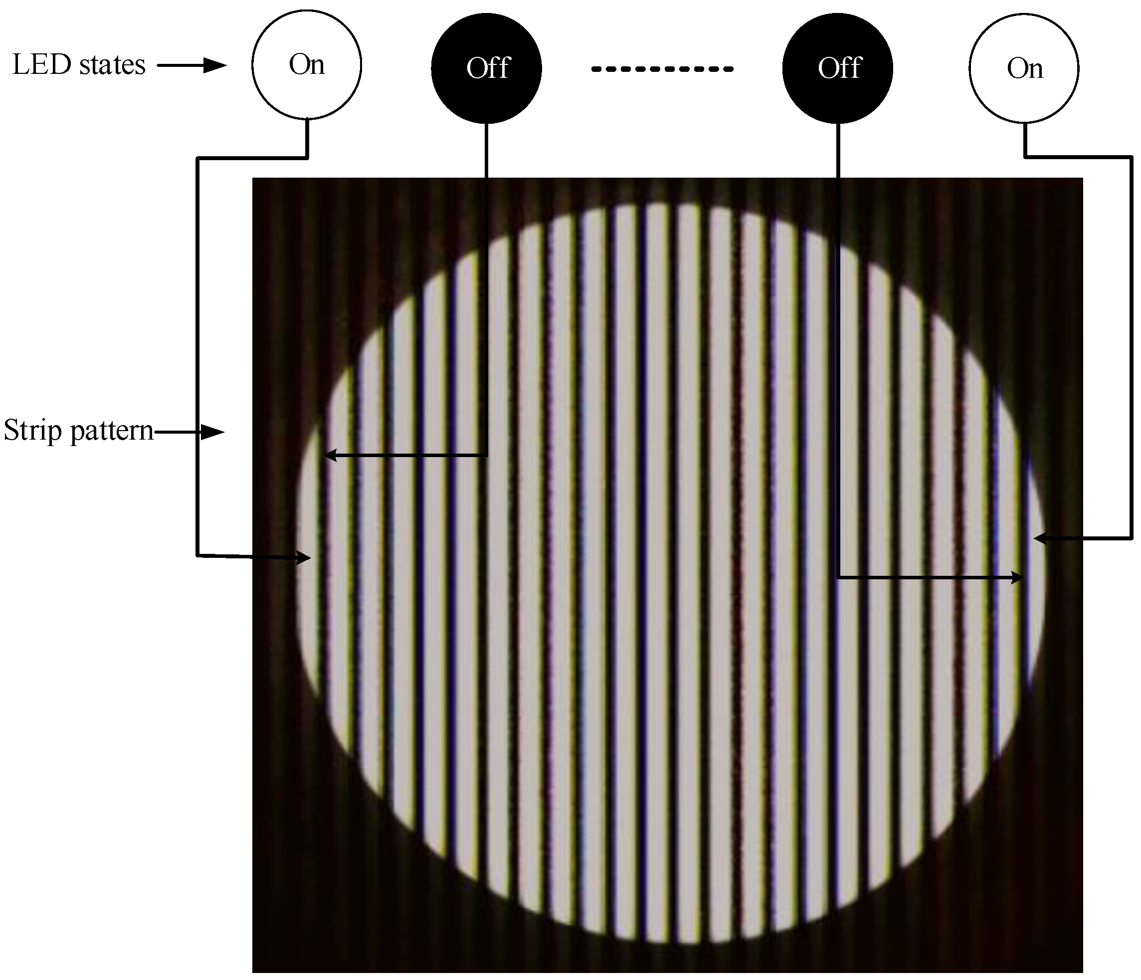
2.1. Data Decoding Principle

An image sensor is built with pixel arrays and a built-in read-out circuit. Each pixel of an image sensor acts as a photodetector. The transmitted bits are decoded through several image-processing techniques. At the beginning of the image processing, the LED is tracked and detected using a camera that utilizes computer vision algorithms. In general, the image frames are examined when the pixels receive optical pulses. Furthermore, each image is converted to grayscale with each pixel having a certain value called the pixel value. Thereafter, a threshold is set to binarize the images. Finally, the data is extracted as binary bits.
There are two techniques that can be used to receive optical pulses sent from an LED: global shutter and rolling shutter. All the pixels of the image sensor are exposed to light at the same time for cameras with the global-shutter technique. However, this technique suffers from a high level of pixel noise [15]. In addition, it is not useful for CMOS image sensors. With the rolling-shutter technique, the image pixels are scanned on a sequential basis. This results in a sequential read-out of pixels that leads to dark and bright strips on the image sensor. The data can be decoded by measuring the strip configurations, which will be discussed further in Section 3.2.

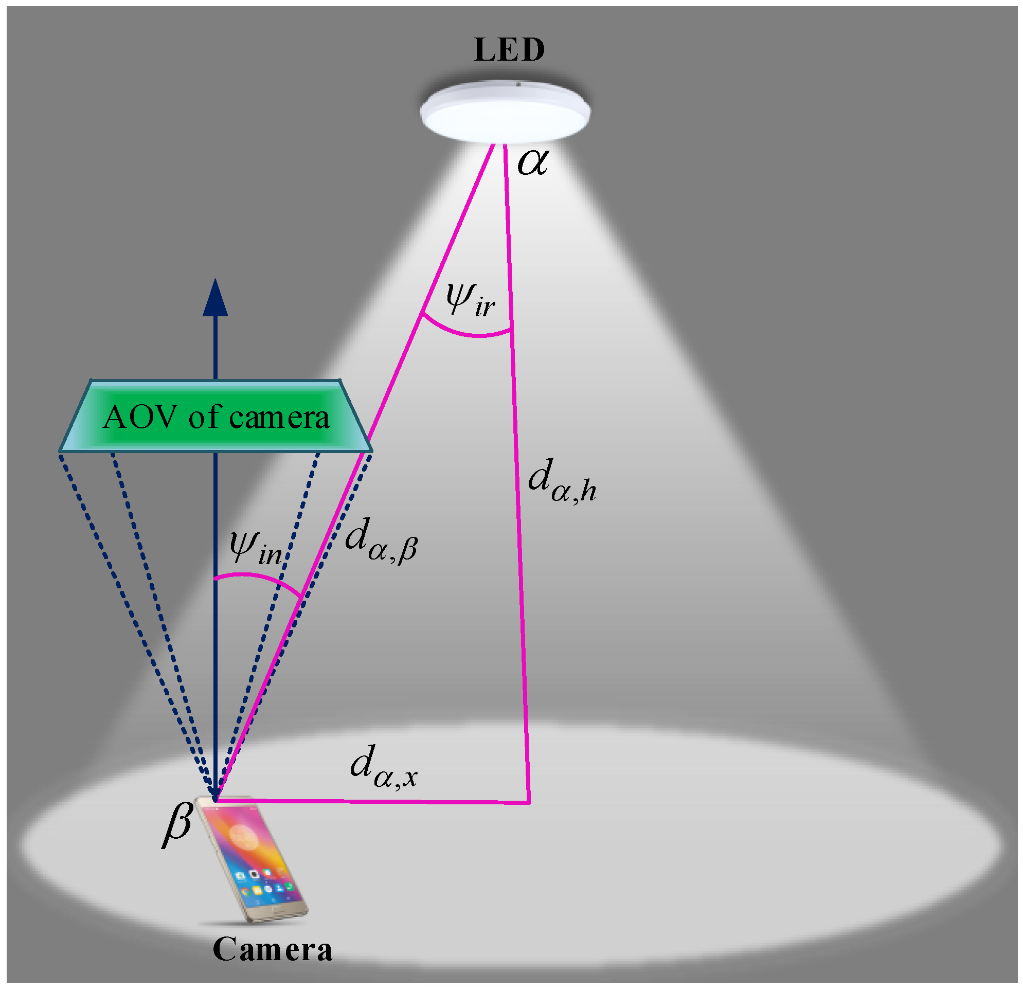
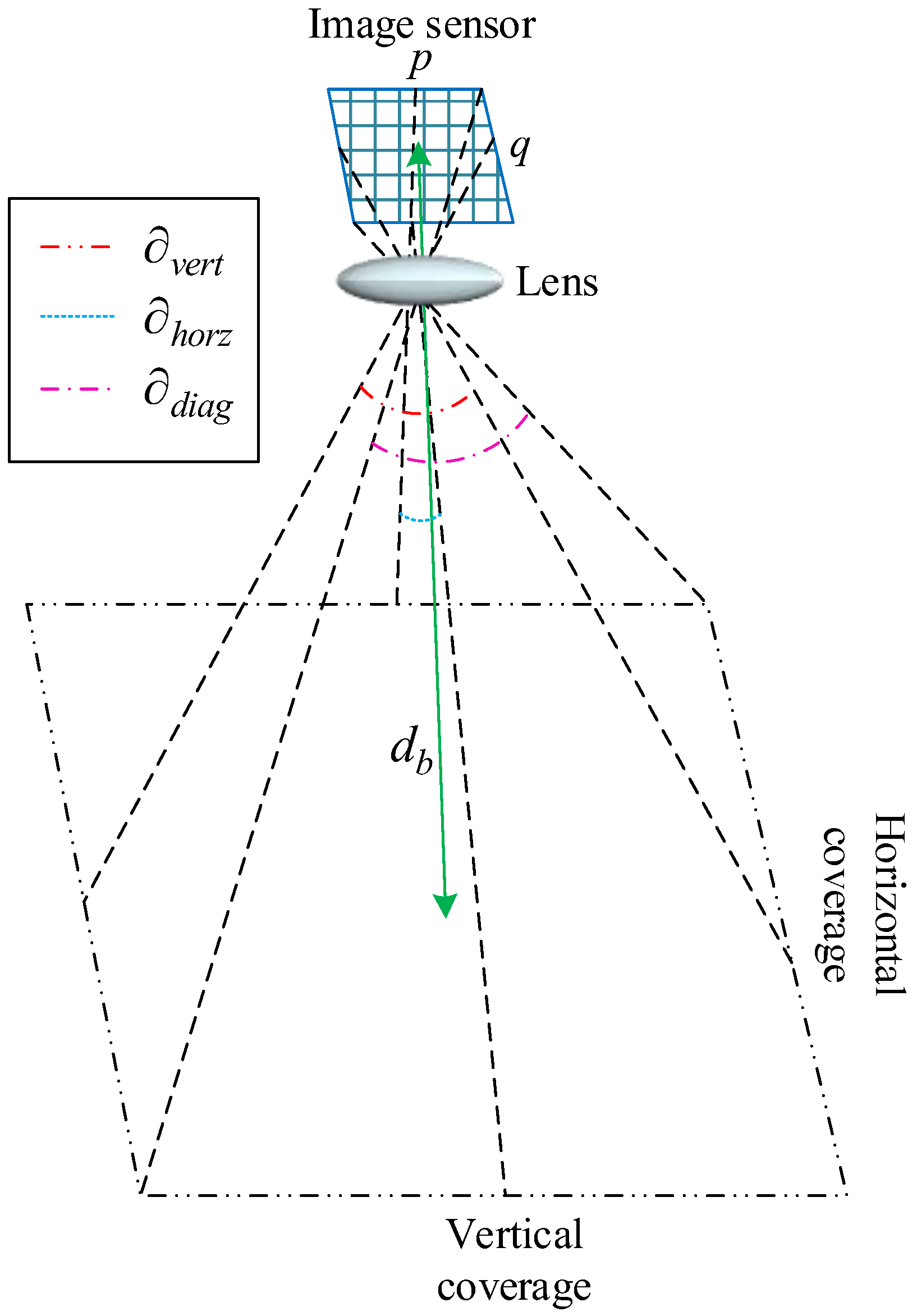
2.2. Illumination Model for Camera Pixels

An OCC data transmission model is illustrated in Figure 2. The channel for optical signal transmission has two components: line-of-sight (LOS) and non-line-of-sight (NLOS). The asperity of the chip faces and the geometric conditions of the encapsulating lens affect the radiation pattern of the LED. The luminous intensity model is represented by the Lambertian radiant intensity [14,16] which is expressed as
R 0 ( ψ i r ) = ( 1 + m l ) cos m l ( ψ i r ) 2 π ,
where ψ i r denotes the angle of irradiance of the LED, and m l is the Lambertian emission index originating from the radiation angle, ς 1 2 , at which the radiation intensity is half of that in the main beam’s direction. m l is defined as
m l = ln 2 ln ( cos ς 1 2 ) .
Assuming that the Euclidean distance between α   and   β is d α , β , the overall DC gain per pixel can be expressed as
H α , β = g o p cos ( ψ i n ) Δ R 0 ( ψ ) A c σ d α , β 2 ,
d α , β = d α , x 2 + d α , h 2
where ψ i n signifies the corresponding angle of incidence, g o p represents the gain of the optical filter, A c is the entire area of the image projected onto the image sensor, σ is the total number of camera pixels illumined by the LED, and Δ is a rectangular function whose value is implied as
Δ = { 0 , ψ i n a o v 1 , ψ i n < a o v ,
where a o v is the AOV of the camera.

2.3. Pixel SINR

There are two things that significantly affect the SINR for OCC. The first one is the interference generated by the neighboring light sources. The second one is the image distortion effects originating from the motion of the users, unfocused images, bad weather (e.g., rain, snowfall, fog, etc.), and long distance between the transmitter and the receiver. Considering these effects, the pixel SINR is represented as
SINR = ( 1 χ ) ( ξ P a v H α , β σ 2 ) 2 j = 0 M ( ξ P a v H j , β σ j 2 ) 2 + q e ξ P a v n A c f r ,   [ χ R : 0 χ 1 ] ,
where P a v is the average transmitted pixel intensity, ξ denotes the optical-to-electrical conversion efficiency per pixel, M is the total number of neighboring OCC transmitters, j is the sequence of a light source, H j , β is the corresponding DC gain received from the specific light source, σ j is the total number of pixels illuminated by that light source, P a v n is the average noise power, q e is the electron charge, R is the set of all real numbers, and f r is the sampling rate of the camera. χ is defined as the image distortion factor that depends on the perspective distortion and lens-blur in the camera imaging process.
Distortions in the image can be reduced to a great extent by accurately focusing the camera using a high-resolution image sensor. The interference generated from the neighboring light sources can be mitigated significantly by applying region of interest signaling [2]. In this technique, the LED light source is detected at a low frame rate. When a region of the LED source is detected, the frame rate is accelerated and the data is demodulated at a high speed. Another method, called selective capturing, can also be used to minimize interference [17]. In this approach, the LED region is captured selectively within the frame. By reducing the captured area, the probability of interference is minimized.
The OCC system’s capacity can be derived from Shannon’s capacity formula. According to Ashok et al. [18], the capacity of a camera-based communication depends on the deterministic nature of the perspective distortions and the Additive white Gaussian noise (AWGN)characteristics of the communication channel and is expressed as
C O C C = f r W s log 2 ( 1 + SINR ) ,
where W s represents the spatial bandwidth denoting the number of information carrying pixels per camera image frame. The parameters that affect the capacity of an OCC system include camera resolution, sampling rate, image distortion factor, and rapidity of LED detection and classification. Among them, the camera sampling rate is considered as the principal factor affecting the data rate performance. Most of the conventional commercial cameras offer low sampling rates (around 30 frames per second). Hence, previous OCC demonstrations using rolling shutter cameras with low-frame rates and conventional intensity modulation schemes showed considerably low data rates [10,19,20,21]. However, the OCC capacity can be significantly improved using cameras with high sampling rates. In addition, the effects of motion blur, background noise, and other interfering elements also limit the overall capacity of an OCC system. These problems can be mitigated by ensuring accurate object focus by the image sensor and by using high-resolution cameras with enhanced focal length.

3. OCC Performance Improvement

The performance of an OCC system depends on the characteristics of the transmitter and the parameters of the camera. This section discusses the effects of these parameters and their appropriate selection based on service requirements and scenarios. In particular, we consider rolling-shutter based cameras for our analysis.

3.1. Focal Length and Pixel Edge Length

The focal length indicates how much of a scene is captured by a camera. The relationship between d α , β and the distance behind the lens at which the focused image is formed ( d i m ) can be expressed according to the Newtonian form of the lens law
( 1 d α , β f o ) ( 1 d i m f o ) = 1 ,
where f o is the focal length of the camera. The object, i.e., the LED light source, needs to be focused appropriately to avoid any kind of image distortion.
The area of the projected image depends on the focal length and the pixel edge length of the image sensor as expressed in
A c = A l f o 2 ρ 2 d α , β 2 ,
where ρ is the pixel edge length and A l is the effective area of the light source exposed to illumination.
It can be noticed that a large focal length effectively contributes to high-distance communication. Here, it is worth mentioning that ρ 2 signifies the size of the image sensor per pixel. The focal length determines the total AOV of the camera. From Figure 3, the AOV can be measured horizontally, vertically, or diagonally. The AOV of a camera with sensor dimensions of p × q can be expressed as
a o v = 2 cos 1 2 f o L 2 + 4 f o 2 ,
here ,   a o v = { v e r t , L = p , h o r z , L = q , d i a g , L = p 2 + q 2 ,
where v e r t ,   h o r z ,   and   d i a g represent the vertical, horizontal, and diagonal AOVs, respectively.
To increase the communication distance, the entire coverage area of the camera should be correspondingly increased. The total area of the camera coverage is illustrated in Figure 3 and can be represented as
d c t = 4 d b 2 tan ( v e r t 2 ) tan ( h o r z 2 ) ,
where d b is the distance between the center of the image sensor and the coverage area. The coverage area is very important in OCC as it determines how much of the area can be utilized to set the LED for data transmission.

3.2. Strip Configurations

The LED transmitter has two states: ON and OFF. These result in dark and bright strips in the LED image onto the rolling shutter image sensors depicted in Figure 4. In the course of image-processing, the number of strips and the width of the strips are employed to recover data streams. The number of strips varies proportionally with the size of the LED.
However, the width of the strips depends strictly on the ON and OFF frequencies of the LED. Different frequencies result in different strip widths. The width of the bright and dark strips can be theoretically expressed as
S = 1 f t r ,   [ Here ,   f = { f o n , if   LED   ON f o f f , if   LED   OFF ]
where t r signifies the time needed to read-out a single pixel of the image, and f o n   and   f o f f indicate the ON and OFF frequencies of the LED light source, respectively. It can be noticed that high-speed cameras with high read-out architectures can provide an excellent communication speed (e.g., 55 Mbps [22]).

3.3. Camera Sampling Rate and Shutter Speed

The performance of OCC is greatly influenced by the sampling rate of the camera. High-frame-rate cameras contribute to high-data-rate communication. However, the majority of the currently available commercial cameras have low frame rates, which led researchers to introduce some undersampling techniques to communicate with these low-frame-rate cameras [8,23]. Recalling Equation (6), it can be noted that the frame rate has a significant effect on the overall SINR and channel capacity. Using high-frame-rate cameras leads to higher data rates. This is because using the on-off keying (OOK) scheme requires the sampling rate to be at least double the LED flickering frequency to satisfy the Nyquist criterion [15]. For the undersampled frequency-shift OOK (UFSOOK), the modulation frequency is a multiple of the frame rate. Therefore, high data rates can be achieved for the same multiples using cameras with high frame rates.
The shutter speed indicates the length of time for which a frame is exposed to light. The shutter speed plays an important role in OCC. A low shutter speed leads to blurring as the LED switches at a high speed. This increases the BER significantly. The shutter speed should be more than twice the frame rate for secure communication. Moreover, the shutter speed should be synchronized with the LED flickering rate as the synchronization establishes how many bits are transmitted during one exposure. As shown in Figure 5, the total number of detectable bits during one exposure is n b . We assume that every pixel of the image sensor is exposed to light for the same amount of time. The opaque portions represent the closed periods of the camera shutter. For simplicity, we consider that the on and off periods of the camera shutter are the same and the total number of exposures per second is m. After synchronization, the number of detectable transmitted bits per exposure can be represented as
n b = 2 f t e ,   [ t s 2 f r ]
where t e denotes the time of a single exposure for a particular frame, and t s indicates the shutter speed.
The exposure time also affects the power received by the image sensor. Data decoding depends on the brightness level of the strips. The exposure time determines how much signal power will be allocated to each pixel. When the exposure time is increased, a higher intensity of light will illuminate the pixels, eventually increasing the signal strength. However, as the image is binarized, a short exposure time will increase the signal strength of the pixels containing the projected image of the LED as compared to the other pixels that result in LED detection with reduced complexity. In addition, longer exposure time will also increase the noise elements. On the contrary, there is a minimum received signal power below which the data cannot be decoded. The number of strips corresponding to that power is analyzed in the next section. Therefore, the exposure time should be set to a certain limit as if the signal strength of the pixels remains beyond the minimum extent.

3.4. LED Size

The LED size significantly determines the communication distance. The number of strips is reduced when the LED is too small. The number of strips for a circular-shaped LED can be expressed as
n s = A l f o 2 ( f o n + f o f f ) t r ρ 2 d α , β 2 .
For the OCC system, there is a minimum number of strips below which the data bits cannot be extracted. The full LED does not need to appear inside the image sensor. The minimum area that should appear depends on the LED size. As shown in Figure 6, the minimum area and the corresponding number of strips considering a circular LED can be expressed as
A m = { 2 r l r m r l r l 2 x 2 d x :   r l > r m , 1 2 A l :   r m = r l , 2 r m r l r m r l 2 x 2 d x :   r m > r l , A l :   r m = 2 r l ,
n s min = A m f o 2 ( f o n + f o f f ) t r ρ 2 d α , β 2
where r l   and   r m represent the LED radius and the minimum portion of it that should appear inside the image sensor, respectively. It is worth noting here that a low n s min decreases the overall received power of the image sensor that can contribute to an increase in the BER.

3.5. MIMO Functionality

Each pixel in an image sensor acts as a photodetector. Due to the nature of the imaging lens, optical signals coming from different directions are imaged in different locations onto the image sensor, which can be utilized as a multiple optical signals receiver. This particularly facilitates the utilization of multiple-input multiple output (MIMO) functionalities in OCC. An OCC-MIMO system is depicted in Figure 7. As illustrated, an array of LEDs can transmit signals simultaneously. As long as the LEDs are positioned inside the AOV of the camera, the projected LED images can be spatially separated from each other. The pixels in the projected images for each LED can be considered as groups that are then separately extracted using image processing and computer vision algorithms.
The performance of an OCC system can be improved significantly using MIMO functionalities. MIMO enhances data rates through spatial multiplexing and provides multiple access conveniences [15]. Luo et al. [13] demonstrated that the communication distance can be significantly increased by employing MIMO using RGB LEDs. Furthermore, by introducing spatial redundancy, the BER can be minimized to a great extent.
An OCC-MIMO tandem is exploited to reduce interference. The images of the LED transmitter, neighboring light sources, and other noise elements are projected at different pixels that are separated afterward, resulting in an excellent SINR for OCC.

4. Modulation Schemes

The most conventional modulation scheme for OCC is OOK. However, a high flickering rate is required for the LEDs to achieve high data rates. Moreover, the camera should be able to receive the data stream, leading to the necessity for cameras to have high sampling rates. The currently available commercial cameras are mostly built to operate at 30 frames per second (fps). To satisfy the Nyquist criterion, the LED flickering rate must not exceed 15 Hz, a frequency too low to be detected by the human eye (the cut-off frequency for the human eye is 100 Hz [24]). Therefore, an appropriate modulation scheme should be chosen for OCC.
The modulation schemes are selected on the basis of service scenarios. This section provides a short description of existing OCC modulation schemes categorized according to the data rate and communication distance. Table 1 summarizes the proposed and implemented modulation techniques for OCC and their features. It is worth mentioning that the implementation of different modulation schemes will have different requirements. The survey was performed to categorize the implemented modulation schemes on the basis of their required features and possible application scenarios.

4.1. Communication Distance

To overcome the limitations of the traditional OOK scheme, several studies [13,23,31] have investigated undersampling modulation schemes for OCC, including UFSOOK and undersampled phase-shift OOK (UPSOOK). UFSOOK can be used for both rolling-shutter and global-shutter cameras; however, this technique suffers from considerably low data rates [15].
RGB LEDs can be used to communicate over long distances using UPSOOK [13]. Several researchers have developed the color-shift keying (CSK) [26,27,28], the undersampled quadrature-amplitude-modulation subcarrier modulation (UQAMSM) [29], and the undersampled pulse-width modulation (UPWM) [31] for OCC. However, these modulation techniques are not useful for long distances, although excellent BERs can be achieved. Another modulation technique called the spatial-2-phase-shift keying (S2-PSK) was proposed specifically for vehicular applications [2]. However, most of the techniques mentioned above do not solve the data rate issue. These techniques can be used in scenarios such as LBS and electronic healthcare (eHealth), where a low BER, rather than data rate, is the prime concern. All the above mentioned schemes can be employed in other environments, such as localized advertising, digital signage, and any outdoor applications, whereas other visible light communication technologies suffer from severe interference.

4.2. Data Rate

Data-rate enhancement is a major issue in OCC performance improvements. The majority of existing modulation techniques do not support high-data-rate communication. OOK, the most conventional scheme for OCC, was utilized in [10] achieving a data rate of 896 bps. However, several studies have already demonstrated healthy data rates by introducing new modulation techniques [12,22]. A data rate of 10 kbps was achieved using a multilevel intensity-modulation (m-IM) technique [30]. The DC-biased optical orthogonal frequency-division multiplexing technique employed by Goto et al. attained a data rate of 55 Mbps [22]. The proposed color intensity modulation combining CSK and multilevel pulse amplitude modulation (PAM) in Reference [12] was able to achieve a data rate of 95 kbps.

5. OCC User Satisfaction

As discussed earlier, the data rate is the main concern in the OCC performance. However, users do not need to achieve a high data rate in every case. Sometimes, an excellent SINR is more significant than a high data rate. For example, if a user wants to localize its position using an LED access point, it will definitely need to achieve a high SINR and an accurate detection of LED to minimize the localization resolution. On the other hand, both SINR and data rate are important for a user who wants to make a video call. User satisfaction in OCC can be represented as the measurement of the communication effectiveness considering the service requirements for the users. It is measured from the required and the achieved data rates and SINRs for OCC users. As we discussed in the previous sections, these factors depend on the camera specifications. The user satisfaction factor in OCC can be expressed as
S = p d ( 1 p b ) φ a κ a φ r κ r ,   [ S R : 0 S 1 ] ,
where φ a   and   φ r denote the achievable and required data rates, whereas κ a   and   κ r indicate the achievable and required SINR, respectively. The expression p b is the bit-error probability and p d signifies the LED detection probability of the LED that depends on the communication distance and whether or not the user is inside the AOV of the camera.

6. Performance Evaluation

This section presents the simulation results on the OCC performance using different values of LED and the camera parameters. Some parameters were kept unchanged, as in Table 2, throughout the simulations. It is worth noting that any variation in the luminaire characteristics will change the simulation results. All the simulations were performed in MATLAB.
As discussed in Section 3.3, the maximum number of detectable bits depends on the modulation frequency and shutter speed of the camera. Figure 8 shows how the number of detectable bits varies with camera exposure time for different LED modulation frequencies. The simulation was performed assuming a communication distance of 2 m between the camera and the LED. The exposure time should be controlled to avoid unexpected motion blurs that lead to increased BERs. A high exposure time also contributes to the increase in the projection of noise elements onto the image sensor that affects the overall SINR. Subsequently, variations in SINR affects the BER performance. Recalling Equation (6), it can be seen that the image distortion factor ( χ ) has an immediate impact on the SINR. The SINR variations for OCC with increasing d α , x for different values of χ are illustrated in Figure 9. The effective f o , a o v , and r l were considered as 26 mm, 60 , and 5 cm, respectively. The distance d α , h was set at 2 m and was kept throughout it. At d α , x = 0 , the LED appears in the center of the image sensor. With increasing d α , x , at a certain point, the projected image of the LED occupies an area corresponding to the minimum number of strips. Note that a significant drop in SINR can be seen in Figure 9. This is because only a part of the LED appears inside the image sensor as the horizontal distance is increased. The OCC achieves an excellent SINR when the full LED appears inside the image sensor. It can be noted that the SINR decreases with higher values of χ . For d α , x = 1   m , an SINR of approximately 18 dB is reduced when χ is increased from 0.1 to 0.4. Hence, lower values of χ show significant SINR improvement. The SINR performance can also be improved using cameras with high pixel densities. This is because the spatial separation of the interfering element from the image sensor is facilitated with high-resolution cameras.
The LED size has a profound impact on OCC performance. A large LED will occupy a high amount of pixels inside the image sensor resulting in a large number of strips. Consequently, the maximum communication distance will be comparatively high. The size of the strips depends on the read-out time and the LED modulation frequency. As discussed in Section 3, the minimum number of strips below which the camera cannot extract the information of the projected image depends on the LED size and the focal length of the camera. Figure 10 shows the number of pixels occupied by the projected image inside the image sensor at different distances from the LED to the camera with different LED sizes and a constant effective focal length of 26 mm. We kept d α , x = 0 and d α , h was varied during performing the simulation to keep the LED at the center. In addition, the LED flickering rate was set to 1.5 kHz resulting in 70 pixels to construct one strip. The minimum number of strips corresponds to the maximum communication distance, which also depends on the focal length. Figure 11 illustrates how the maximum communication distance varies with respect to the LED size and the effective focal length. It can be seen that the maximum communication distance can be enhanced using larger LEDs. Compared to an LED size of 1 cm, the communication-distance improvement of 2.5 and 4 times can be noticed for LEDs with 5 cm and 10 cm, respectively. Both simulations in Figure 10 and Figure 11 were performed at a constant noise spectral density of 10 21 . It is worth stating that effective communication will be achieved if the LED is clearly focused on the camera; otherwise, it will result in a significant increase in the BER. Moreover, there is a minimum SINR below which data bits cannot be decoded.
Figure 12 illustrates the outage probability for OCC for different AOVs of the camera. The effective focal length and LED radius were the same for the second simulation. It can be seen that the probability of outage increases as the AOV is reduced. In addition, the outage probability increases as the LOS distance between the LED and the camera increases. Therefore, it can be outlined that the outage probability can be improved by increasing the camera AOV, which can be achieved by enhancing the resolution of the image sensor.
The capacity of an OCC system significantly depends on the camera parameters. Increasing the camera sampling rate can improve the OCC capacity to a considerable extent. The cumulative distribution function (CDF) of the theoretical data-rate limit for different camera sampling rates is depicted in Figure 13. The simulation was performed for different Euclidean distances between the LED and the camera that are ranged from 0.5 m to 5 m. The CDF is zero at distances higher than approximately 4.472 m. As shown in Figure 13, the data rate performance is significantly improved with higher frame rates. In case of a sampling rate in the range of a few kfps, the OCC capacity of up to several Mbps can be achieved. Moreover, it can be noted that the variation in OCC capacity is not considerably severe (16–28 kbps at 30 fps) with increasing communication distance.
As discussed in Section 5, user satisfaction with OCC depends on the service types and requirements. A user making a voice call requires a lower data rate compared to a user engaged in a video call. However, a user who uses OCC for LBS requires a good SINR rather than a high data rate. Figure 14 illustrates the variations in the user satisfaction factor with respect to SINR, evaluated in terms of different data rates. This evaluation is generalized with a satisfaction factor above 0.5 considered as good and a factor above 0.8 as excellent.

7. Conclusions and Future Research

OWC has already been proved to be a congruent complementary technology to RF, with the potential of being integrated into the next-generation of wireless technologies. OCC is a promising OWC system that can be employed to receive data from existing LED infrastructures using cameras. Despite its advantages, OCC suffers from some limitations that degrade its overall performance. In this study, several performance-improvement techniques for OCC mainly focusing on the transmitter and receiver parameters are discussed. A great deal of attention was given to enhancing the user data rate and SINR. Existing modulation techniques for OCC and their application environments were also discussed. In addition, an analysis of user satisfaction was performed to demonstrate the optimal OCC settings for users in different service scenarios. Our future work will include the implementation and testing of the optimality of OCC systems to achieve a high data rate in long-distance communication. Moreover, very few studies have investigated the effects of the communication channel parameters on OCC data reception, which could be another significant research topic for OCC performance improvements. Future research will also include the integration of OCC in optical hybrid infrastructures by utilizing the useful features offered by current OCC systems.

Author Contributions

All authors contributed to this paper. Specifically, M.K.H. and M.Z.C. proposed the idea and wrote the paper; M.K.H. and M.S. performed the simulations; M.Z.C. and V.T.N. analyzed and verified the simulation data; and Y.M.J. supervised the work and provided funding support.

Funding

This research was supported by the MSIT (Ministry of Science and ICT), Korea, under the ITRC (Information Technology Research Center) support program (IITP-2018-0-01396) supervised by the IITP (Institute for Information & communications Technology Promotion).

Conflicts of Interest

The authors declare no conflict of interest.

References

  1. Chowdhury, M.Z.; Hossan, M.T.; Islam, A.; Jang, Y.M. A comparative survey of optical wireless technologies: Architectures and applications. IEEE Access 2018, 6, 9819–9840. [Google Scholar] [CrossRef]
  2. Islam, A.; Hossan, M.T.; Jang, Y.M. Convolutional neural network scheme–based optical camera communication system for intelligent Internet of vehicles. Int. J. Distrib. Sens. Netw. 2018, 14. [Google Scholar] [CrossRef]
  3. Yamazato, T.; Kinoshita, M.; Arai, S.; Souke, E.; Yendo, T.; Fujii, T.; Kamakura, K.; Okada, H. Vehicle motion and pixel illumination modeling for image sensor based visible light communication. IEEE J. Sel. Areas Commun. 2015, 33, 1793–1805. [Google Scholar] [CrossRef]
  4. Takai, I.; Harada, T.; Andoh, M.; Yasutomi, K.; Kagawa, K.; Kawahito, S. Optical vehicle-to-vehicle communication system using LED transmitter and camera receiver. IEEE Photonics J. 2014, 6, 1–14. [Google Scholar] [CrossRef]
  5. Lin, B.; Ghassemlooy, Z.; Lin, C.; Tang, X.; Li, Y.; Zhang, S. An indoor visible light positioning system based on optical camera communications. IEEE Photonics Technol. Lett. 2017, 29, 579–582. [Google Scholar] [CrossRef]
  6. Armstrong, J.; Sekercioglu, Y.A.; Neild, A. Visible light positioning: A roadmap for international standardization. IEEE Commun. Mag. 2013, 51, 68–73. [Google Scholar] [CrossRef]
  7. Shahjalal, M.; Hossan, M.T.; Hasan, M.K.; Chowdhury, M.Z.; Le, N.T.; Jang, Y.M. An implementation approach and performance analysis of image sensor based multilateral indoor localization and navigation system. Wirel. Commun. Mob. Comput. 2018, 2018, 7680780. [Google Scholar] [CrossRef]
  8. Luo, P.; Ghassemlooy, Z.; Minh, H.L.; Tang, X.; Tsai, H.M. Undersampled phase shift ON-OFF keying for camera communication. In Proceedings of the International Conference on Wireless Communications and Signal Processing (WCSP), Hefei, China, 23–24 October 2014. [Google Scholar]
  9. Lee, H.; Lee, I.; Lee, S.H. Deep learning based transceiver design for multi-colored VLC systems. Opt. Express 2018, 26, 6222–6238. [Google Scholar] [CrossRef]
  10. Chow, C.; Chen, C.; Chen, S. Enhancement of signal performance in LED visible light communications using mobile phone camera. IEEE Photonics J. 2015, 7, 1–7. [Google Scholar] [CrossRef]
  11. Nagura, T.; Yamazato, T.; Katayama, M.; Yendo, T.; Fujii, T.; Okada, H. Improved Decoding Methods of visible light communication system for ITS using LED array and high-speed camera. In Proceedings of the IEEE Vehicular Technology Conference, Taipei, Taiwan, 16–19 May 2010. [Google Scholar]
  12. Tian, P.; Huang, W.; Xu, Z. Design and experimental demonstration of a real-time 95kbps optical camera communication system. In Proceedings of the International Symposium on Communication Systems, Networks and Digital Signal Processing (CSNDSP), Prague, Czech Republic, 20–22 July 2016. [Google Scholar]
  13. Luo, P.; Zhang, M.; Ghassemlooy, Z.; le Minh, H.; Tsai, H.; Tang, X.; Png, L.C.; Han, D. Experimental demonstration of RGB LED-based optical camera communications. IEEE Photonics J. 2015, 7, 1–12. [Google Scholar] [CrossRef]
  14. Kahn, J.M.; Barry, J.R. Wireless infrared communications. Proc. IEEE 1997, 85, 265–298. [Google Scholar] [CrossRef] [Green Version]
  15. Saha, N.; Ifthekhar, M.S.; Le, N.T.; Jang, Y.M. Survey on optical camera communications: Challenges and opportunities. IET Optoelectron. 2015, 9, 172–183. [Google Scholar] [CrossRef]
  16. Hasan, M.K.; Chowdhury, M.Z.; Shahjalal, M.; Jang, Y.M. Fuzzy based network assignment and link-switching analysis in hybrid OCC/LiFi system. Wirel. Commun. Mob. Comput. 2018, 2018, 2870518. [Google Scholar] [CrossRef]
  17. Teli, S.; Chung, Y. Selective capture based high-speed optical vehicular signaling system. Signal Process. Image Commun. 2018, 68, 241–248. [Google Scholar] [CrossRef]
  18. Ashok, A.; Jain, S.; Gruteser, M.; Mandayam, N.; Yuan, W.; Dana, K. Capacity of screen-camera communications under perspective distortions. Pervasive Mob. Comput. 2015, 16, 239–250. [Google Scholar] [CrossRef]
  19. Liang, K.; Chow, C.; Liu, Y. Mobile-phone based visible light communication using region-grow light source tracking for unstable light source. Opt. Express 2016, 24, 1–6. [Google Scholar] [CrossRef] [PubMed]
  20. Chow, C.; Chen, C.Y.; Chen, S.H. Visible light communication using mobile-phone camera with data rate higher than frame rate. Opt. Express 2015, 23, 26080–26085. [Google Scholar] [CrossRef]
  21. Ji, P.; Tsai, H.; Wang, C.; Liu, F. Vehicular visible light communications with LED taillight and rolling shutter camera. In Proceedings of the IEEE 79th Vehicular Technology Conference, Seoul, Korea, 18–21 May 2014. [Google Scholar]
  22. Goto, Y.; Takai, I.; Yamazato, T.; Okada, H.; Fujii, T.; Kawahito, S.; Arai, S.; Yendo, T.; Kamakura, K. A new automotive VLC system using optical communication image sensor. IEEE Photonics J. 2016, 8, 1–17. [Google Scholar] [CrossRef]
  23. Roberts, R.D. Undersampled frequency shift ON-OFF keying (UFSOOK) for camera communications (CamCom). In Proceedings of the Wireless and Optical Communication Conference, Chongqing, China, 16–18 May 2013. [Google Scholar]
  24. Kim, B.W.; Jung, S. Novel flicker-free optical camera communications based on compressed sensing. IEEE Commun. Lett. 2016, 20, 1104–1107. [Google Scholar] [CrossRef]
  25. Roberts, R.D. MIMO protocol for camera communication (CamCom) using undersampled frequency shift ON-OFF keying (UFSOOK). In Proceedings of the Optical Wireless Communications GlobeCom Workshop, Atlanta, GA, USA, 9–13 December 2013. [Google Scholar]
  26. Chen, S.; Chow, C. Color-shift keying and code-division multiple-access transmission for RGB-LED visible light communications using mobile phone camera. IEEE Photonics J. 2014, 6, 1–6. [Google Scholar] [CrossRef]
  27. Hu, P.; Pathak, P.H.; Feng, X.; Fu, H.; Mohapatra, P. Colorbars: Increasing data rate of LED-to-camera communication using color shift keying. In Proceedings of the ACM International Conference on Emerging Networking and Experiments and Technologies, Heidelberg, Germany, 1–4 December 2015. [Google Scholar]
  28. Singh, R.; O’Farrell, T.; David, J.P.R. An enhanced color shift keying modulation scheme for high-speed wireless visible light communications. J. Lightw. Technol. 2014, 32, 2582–2592. [Google Scholar] [CrossRef]
  29. Luo, P.; Zhang, M.; Ghassemlooy, Z.; le Minh, H.; Tsai, H.; Tang, X.; Han, D. Experimental demonstration of a 1024-qam optical camera communication system. IEEE Photonics Technol. Lett. 2014, 28, 139–142. [Google Scholar] [CrossRef]
  30. Rachim, V.P.; Chung, W. Multilevel intensity-modulation for rolling shutter-based optical camera communication. IEEE Photonics Technol. Lett. 2018, 30, 903–906. [Google Scholar] [CrossRef]
  31. Luo, P.; Jiang, T.; Haigh, P.A.; Ghassemlooy, Z.; Zvanovec, S. Undersampled pulse width modulation for optical camera communications. In Proceedings of the IEEE International Conference on Communications Workshops (ICC Workshops), Kansas City, MO, USA, 20–24 May 2018. [Google Scholar]
Figure 1. The schematic block diagram of an OCC system.
Applsci 08 02527 g001
Figure 2. The System model.
Applsci 08 02527 g002
Figure 3. The illustration of the camera coverage.
Applsci 08 02527 g003
Figure 4. The strip configurations for OCC.
Applsci 08 02527 g004
Figure 5. The relationship between camera exposure time and the number of detectable bits.
Applsci 08 02527 g005
Figure 6. An illustration of the minimum LED area required to decode data bits.
Applsci 08 02527 g006
Figure 7. The depiction of the OCC-MIMO system.
Applsci 08 02527 g007
Figure 8. The variation of the maximum number of detectable bits with respect to the exposure time.
Applsci 08 02527 g008
Figure 9. The variation of the SINR by changing the horizontal distance between the camera and the LED.
Applsci 08 02527 g009
Figure 10. The variation of the projected image size onto the image sensor with changing vertical communication distances.
Applsci 08 02527 g010
Figure 11. The maximum communication distance vs focal length for different LED sizes.
Applsci 08 02527 g011
Figure 12. The outage probability for OCC for different LOS distance between the LED and the camera.
Applsci 08 02527 g012
Figure 13. The cumulative distribution function of the OCC capacity.
Applsci 08 02527 g013
Figure 14. The illustration of user satisfaction with OCC.
Applsci 08 02527 g014
Table 1. The features of the OCC modulation schemes and their applications.
SchemeRGB LEDUnder SamplingFrame Rate (fps)Data RateDistancePossible Application Scenarios
OOK [10]××28896 bps25 cmLBS
UFSOOK [21,23,25]×30 [21]15 bps [21]40 cm [21]V2X, LBS
CSK [26,27,28]×30 [26,27]240 bps [26]
5.2 kbps [27]
50 cm [26]
3 cm [27]
LBS
UPSOOK [13]50150 bps60 mV2X
UQAMSM [29]×50500 bps1.5 mLBS
m-IM [30]×30>10 kbps2 mDigital signage, LBS
UPWM [31]×30150 bps1 mLBS
DCO-OFDM [22]×3055 Mbps1.5 mV2X, AR
CSK and multilevel PAM [12]×33095 kbps1.2 mV2X and large data transfer
Table 2. The system parameters for the simulations.
LED Parameters
Gain of the optical filter, g o p 1
Transmitted optical power10 W
Half-intensity radiation angle, ς 1 2 60
Camera Parameters
Image sensor size, p × q 6 × 4 (3:2 aspect ratio)
Pixel edge length, ρ 1.8   μ m
Camera optical to electrical conversion efficiency, ξ 0.51

