Article

Numerical and Experimental Investigations of a Micromixer with Chicane Mixing Geometry

by
Valentin Khaydarov
1,
Ekaterina S. Borovinskaya
1,2,* and
Wladimir Reschetilowski
1,2
1
Technische Universität Dresden, 01062 Dresden, Germany
2
Saint-Petersburg State Institute of Technology (Technical University), 190013 St. Petersburg, Russia
*
Author to whom correspondence should be addressed.
Appl. Sci. 2018, 8(12), 2458; https://doi.org/10.3390/app8122458
Submission received: 25 October 2018 / Revised: 19 November 2018 / Accepted: 27 November 2018 / Published: 2 December 2018
(This article belongs to the Section Chemical and Molecular Sciences)

Abstract

:
A micromixer is a new type of chemical engineering equipment used to intensify the mixing process. This article provides details on flow regimes in microchannels with a complex geometry, such as with chicane mixing geometry. Experiments involving water, ink, and a micro digital camera have determined both the micromixer’s initial mixing zone, and also the streamlines. Computational fluid dynamics (CFD) modelling helped identify the mechanism of stimulating effect; swirling and recirculation were identified as two special cases of the convective mixing process. To characterize the degree of mixing, a function of volume flow rate was proposed. A much higher degree of mixing in vortex flow compared to stratified flow was observed. The relationship between laminar flow and vortices shows a square-law dependence of pressure drop against the volume flow rate. The mixing cost and the mixing energy cost at Reynolds number of 50 are higher for the chicane micromixer than for micromixers without chicanes geometry.

Graphical Abstract

1. Introduction

Nowadays, micromixers and microreactors are used in a wide range of chemical reactions, from simple homogenous mixing to catalytic and biochemical processes [1]. Some pilot plants based on microstructured systems have been reported [2], which indicates the potential for novel microstructured systems in the chemical industry. Their advantages are based on extremely small dimensions which lie in the range from some micrometers to a few millimeters. This reduces the diffusion length and the mixing time in comparison with conventional reactors. The volume of micromixers varies from microliters to milliliters. This provides better process control (e.g., temperature) and better safety when working with dangerous or explosive substances. Moreover, the microstructured systems operate continuously, providing wide scale-up possibilities, e.g., parallel running of several microreactors in order to increase the setup performance.
In non-micro systems such as in huge pipes or vessels, an increase in mixing rate is mainly reached using turbulent flow regimes and relatively high values of Reynolds number (Re > 2400). However, this leads to an instability in flow, as well as to higher energy costs. In contrast to conventional reactors, Reynolds numbers in microfluidic systems are relatively small (Re < 10) and the flow is laminar. The mixing effect is stronger in comparison with conventional reactors due to a significant decrease in diffusion length and a significant increase in the interfacial area between the species. More complex and effective geometric structures, such as micromixers based on multilamination focusing and splitting-and-recombination effects were developed to increase the interfacial area and stimulate the mixing process [1,3,4,5,6].
There are two main types of micromixers: active and passive. Active micromixers use external energy sources to accelerate the mixing process (acoustic, periodic pressure, temperature fields, etc.) [3,4]. In contrast to active micromixers, passive ones do not need external energy sources, but use special geometric structures of mixers and channels. The passive micromixers are also divided into two types depending on the primary mixing process: based on the molecular diffusion (laminar micromixers) and based on the chaotic advection (convective micromixers).
The laminar micromixers, which use diffusion as a primary mixing process, obey Fick’s law and are limited by molecular diffusion lengths. Consequently, geometry, residence time, and dimension of channels of such microfluidic devices play an especially significant role. Small characteristic lengths and low flow rates lead to low values of Reynolds number, which normally equals Re < 10. In some cases, with sample geometries such as a T-mixer, the diffusion continues to be the main mixing process with Reynolds numbers up to Re = 75 [7]. This laminar flow regime with parallel streamlines without vortices is well-known as “stratified flow”, whereas the main mixing process is via diffusion. However, diffusion is rather a slow process with mixing times of up to several minutes. Special microreactor geometries (interdigital [8], split-and-recombine [9], focusing [10], etc.) were designed to focus, stretch, or recombine the flow and as a result decrease the characteristic mixing length and improve the mixing process.
Microreactors based on chaotic advection provide intensification of the mixing process due to vortices generation. The guided flow streaming lead to hydrodynamic instabilities and can significantly improve the transverse mass transfer. Convective micromixers largely operate with high values of the Reynolds number Re > 10, but this value depends directly on the geometry and varies from Re = 0.02 (for a spiral channel micromixer [11]) up to Re = 50 (for a T-mixer [12]). In convective micromixers, mixing stimulation is achieved by vortices, which appear according to domination of inertial to viscous forces. As a result, the lamellas become thinner, the diffusion length decreases and therefore, the flows mix more quickly. This effect is called secondary flows, which Dean [13,14] explored for the first time. He included the significant change of the velocity field in curved pipes and the resulting formation of vortices, and the flow remained laminar. Nowadays, the utilization of this phenomenon is called “vortex flow”, which finds its application in curved microchannels, such as in T-form mixers [7,15,16], Y-form mixers [16], spiral microchannels [17], herringbone [18], chicane or serpentine [19], with embedded obstructions [20], etc. The most important feature of these microreactors is an effect of the volume flow rate on intensity of vortex structures appearing [21] and on the chemical performance [22].
While the vortex flow is characterized by the symmetry of both mixed flows, the engulfment flow has no symmetry [12]. Broken symmetry results in the flow reaching the opposite side of the mixing channel. This significantly reduces the diffusion length and further intensifies the mixing process.
In comparison to diffusion micromixers, convective micromixers utilizing vortex and engulfment flow regimes provide faster mixing but also have several disadvantages, such as higher values in the decrease of pressure. To solve this, the supply pumps with higher power and higher energy consumptions are to be operated. In addition, the tubing should be more robust in order to withstand higher pressure. In turn, this increases setup and operating costs.
The investigation of flow regimes such as stratified, vortex, and engulfment flows is challenging because every type of micromixer is unique in its geometrical structure and therefore has its own range of the flow regimes and vortex patterns.
Several researches investigated the mixing process in a micromixer with meander structures similar to that being investigated in the present study. Mengeaud and co-authors [19] have investigated a micromixer with 100 µm-wide zig-zag channel. Zigzag elements have a positive effect on mixing in comparison with a straight channel. Moreover, mixing efficiency greatly increases for Reynolds numbers Re > 80, which was explained by the flow recirculation phenomenon.
Parsa and Hormozi [23] have studied in their article a sinusoidal wave form micromixer with different phase shifts. The shift at 3/4 π shows the best mixing index, while shifts at 0 (pure sinusoidal form) and pi (symmetrical form) have a much smaller mixing index, as well higher critical Reynolds. Ziegenbalg et al. [21] investigated and compared a Y-junction and an “S-form” micromixer using a computational fluid dynamics (CFD) simulation. The results showed the higher mixing efficiency of the “S-form” mixer in comparison to the Y-mixer only by vortex flow regime. In the case of stratified flow, only the hydraulic diameter plays a role and there is no difference between the Y-mixer and the “S-form” mixer in hydraulic diameter dh = 1 mm.
Schwolow et al. [24] experimentally investigated the mixing process of “S-form” micromixers using two different indicative reactions: consecutive Diazo Coupling and parallel neutralization and hydrolysis reactions. They showed that the high mixing index can only be achieved using a vortex flow and there is likely a correlation between mixing index and pressure drop. It was also experimentally found, that the volume flow rate plays a significant role in the mixing process in this type of micromixers. There are zones with almost zero mixing efficiency, stagnation zones and many areas, where previously mixed flows mix again.
Holvey et al. [25] studied a neutralization reaction in a similar tangential micromixer—FlowPlate™ 102 and 260, produced by Lonza. The results indicated that at comparable Reynolds numbers the S-shaped channel allows faster mixing in comparison with the SZ-shaped and caterpillar channels.
A micromixer with a similar structure was investigated by Alam et al. [26]. The results showed a sharp increase of mixing index by Re > 10 due to observed recirculation in micromixers cells.
Schwarz et al. [27] showed an effectiveness of utilizing a chicane channel using a Villermaux-Dushman reaction. The maximal conversion was stated between Q = 0.5 mL/min and Q = 0.75 mL/min in case of flows diluted in water with the same volume flow rate. Although this cannot indicate the optimal volume flow rate, it proves great mixing efficiency when using higher flow rates.
Ansari et al. [28] have investigated a micromixer with circular mixing chambers, which are similar to the meander elements in the investigated micromixer. According to the results, the mixing index increases rapidly with the Reynolds number and the recirculation zones play a crucial role especially in case of Reynolds numbers Re > 5. Moreover, the square-law dependency of the pressure drop from the Reynolds numbers was found.
From the above references, it is obvious that both meander design and circular zones with recirculation do enhance mixing, but the main condition for the effect are high values of Reynolds numbers. This study is aiming to research the acceleration of the mixing process in detail and its connection with flow regimes in a wide range of Reynolds numbers (from 0.05 to 259).
The aim of most studies was an investigation of a micromixer with only a zigzag, meander, or circular chamber structure, while the micromixer in the present study consists of meander elements as well as recirculation chambers. In this work, different flow regimes, their ranges, influence on mixing intensity and pressure drop in the passive micromixer with chicane mixing geometry (“S-form”) are investigated. Information about the flow regimes and their effects in the micromixers can open new opportunities in mass-transport process acceleration, such as when using vortex flow or engulfment flow regimes. The study was carried out in two stages. Firstly, the numerical simulation was made with varying Reynolds number. Secondly, in order to verify the simulation results, some experiments using a microphotography analysis unit were also carried out.

2. Materials and Methods

2.1. Micromixer Description

The micromixer LTF-MS, with a complex structure of “chicanes” or an “S-form” channel, made by Little Things Factory GmbH (Elsoff, Germany), was chosen for this study. The investigated micromixer contains a Y-mixer and S-type microchannel (or “chicane” type), the latter includes specially designed meander elements (here and further, the term “meander” is associated with the repeated part of the “chicanes” channel). The micromixer is shown in Figure 1a.
The micromixer represents a plate made entirely of borosilicate glass (Borofloat® 33) with three connectors. The glass material makes it possible to run experiments and allows easy optical analysis using colored flows, fluorescence methods, or to indicate reactions [3]. Small dimensions of the micromixer lead to high values of heat-dissipation, so we can ignore the temperate gradient within the flow for the purposes of this study, and an isothermal model can be applied.
The understudied micromixer consists of two pre-inlet channels, the Y-mixer, micromixing channel with meander elements and long outlet channel. The pre-inlet channels have a diameter of 1 mm and are used as pre-tempering units. Their material and small diameter provide intensive heat transfer. The Y-mixer has a 90° angle between elbows and the same 1 mm diameter. The mixing channel contains 22 meander elements with an alternate direction of curvature. A more detailed sketch is represented in Figure 1b.

2.2. Experimental Setup and Post Processing

For the purposes of verifying the simulation results, some experiments were carried out. Experimental setup consisted of two non-pulse syringe pumps (NE-300 Just Infusion™, New Era Pump Systems, Inc., Farmingdale, NY 11735, USA) and the micromixer LTF-MS connected using PVC-pipes (Figure 2). A micro digital camera (DNT DigiProfi, camera resolution 2592 × 1944, frame rate—30 frames/s, focus range—10 mm) was used for taking photographs of the initial mixing in the micromixer. The experiments with colored ink and water were carried out at a temperature of 22 °C, and volume flow rate of both inflows were equal and varied from 0.5 mL/min to 10 mL/min.
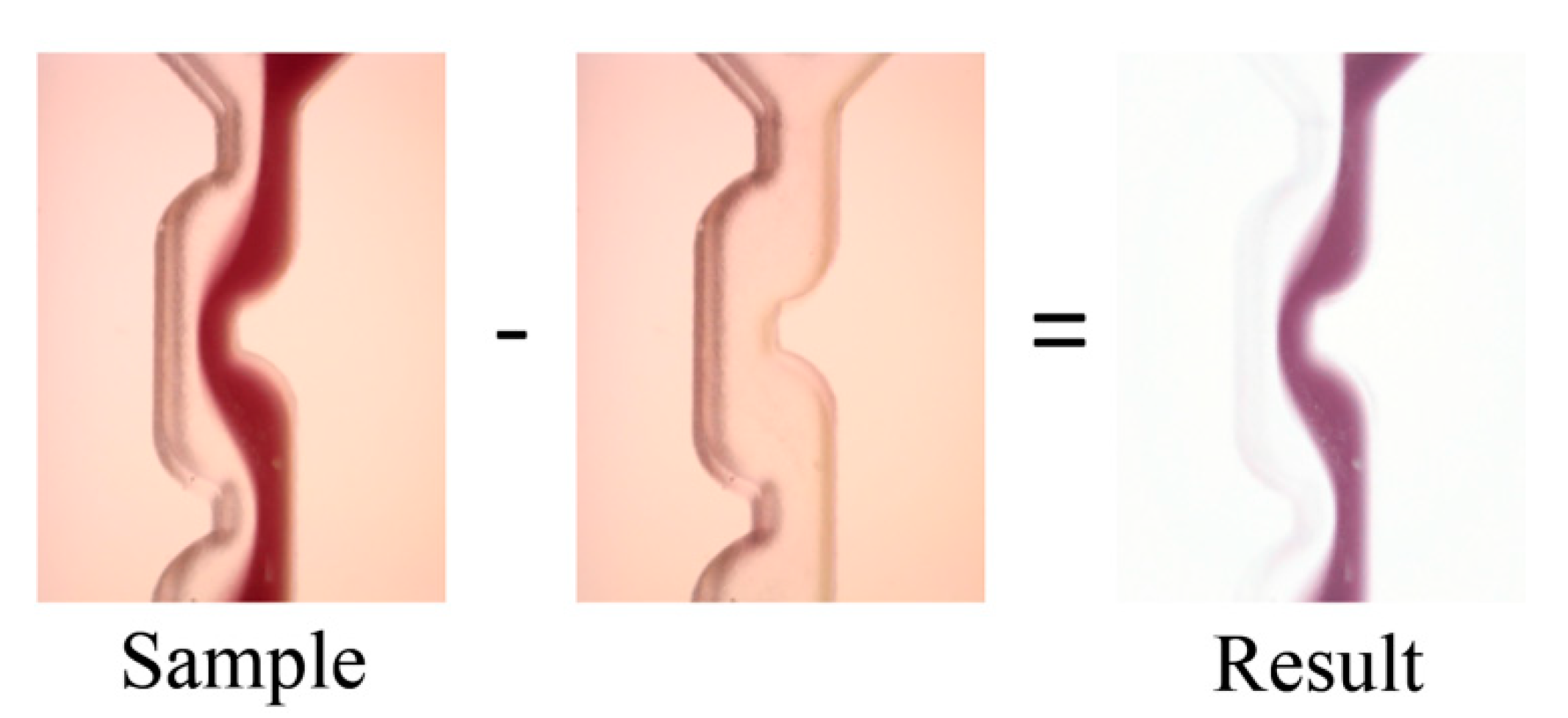
In order to get the picture of only species inside the channel a special procedure was carried out. Before the experiments with color flow, the micromixer was filled with a transparent fluid and the picture was captured. This picture was used as zero-level and further subtraction from the sample pictures (Figure 3). The processing of the pictures was made using a self-written routine in Wolfram Mathematica.

2.3. Numerical Simulation

In order to achieve high accuracy of the simulation and due to a limited performance capacity of the computing system, only the Y-mixer and the first 4 meanders have been computed. The simulation was performed using the СFD software ANSYS CFX, version 14.0, utilizing a finite volume method and a coupled solver.
The mathematical model consists of a steady-state Navier-Stokes equation for incompressible flow of Newtonian fluids and the diffusion-convection transport equation.
ρ v · v = p + η 2 v v = 0 · ( D C ) · ( v C ) = 0
The fluid is assumed to be isothermal and the process is steady-state.
The walls of the micromixer have no-slip boundary conditions. Special consideration should be given to inlet boundary conditions. It was shown by Galletti et al. [29], that the inlet velocity profile has a significant influence on the mixing process. For this reason, two 4.5 mm long channels were added before the Y-mixer. Moreover, fully developed velocity profiles in a round channel were applied on both inlets. At the outlet, the zero static pressure was used as the outlet boundary condition. An additional section with a straight channel was added after the last meander element in order to avoid the backflow effect.
Because strongly diluted solutions were used in the experiments, the properties of the two working fluids were determined as related parameters of water at a temperature T = 20 °C. The density, viscosity and diffusion coefficient were set as ρ = 998 kg/m3, μ = 10−3 Pa·s and D = 2 × 10⁻⁹ m2/s.
For the determination of flow regimes, the Reynolds number was calculated as:
Re = vLρ/μ
where L = 1 mm.
A mixing index was used to estimate the grade of mixing. It is derived from the degree of segregation, proposed by Danckwerts [30]. The mixing index I M represents the ratio of species homogeneity and varies from 0 (for a completely segregated species) to 1 (for a completely mixed species):
IM = 1 − (IS)1/2 = 1 − (σ22max)1/2
where σ —is the variance of concentration, σ max —the maximal variance of concentration, I S —the degree of segregation. These parameters can be estimated in this way:
σ = 1 A A ( C C ¯ ) 2 dA   and   σ max = 1 A A C ( 1 C ) dA
where C —the concentration and A—the cross-sectional area.
The discretization in CFD applications is a very important procedure [31]. The so-called numerical diffusion plays a crucial role in the simulation of the mixing process. To decrease numerical induced diffusion, the second-order discretization scheme is used. According to high values of gradients, the double precision for the calculations has been used, therefore increasing accuracy. Convergence criteria were defined as followed:
  • Residuals RMS are less than 1 × 10⁻⁶;
  • Domain imbalances are less than 0.1%.
Average mixing index in outlet section reaches a steady solution (variation is less than 1% in comparison with the previous iteration).
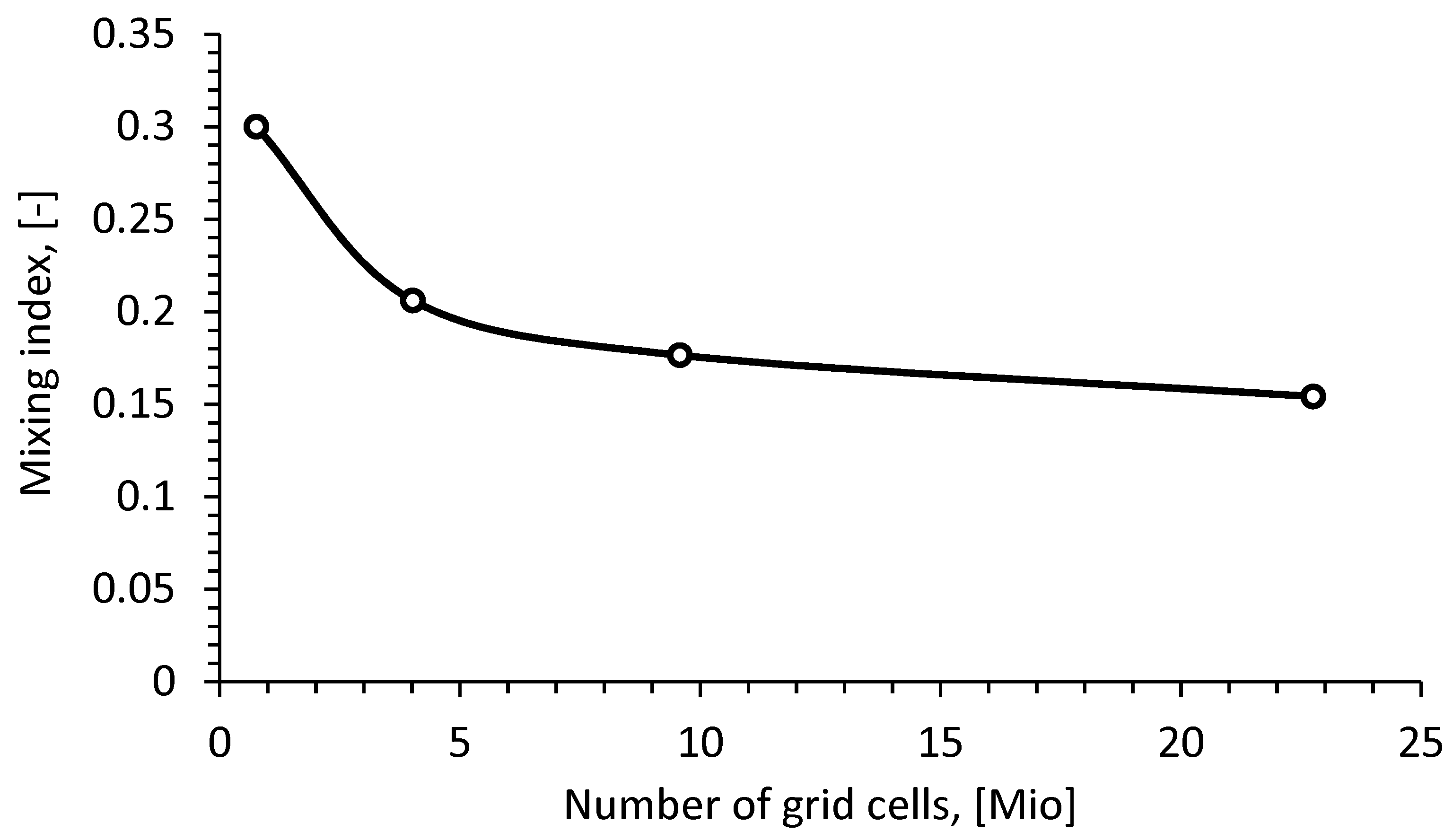
Moreover, the grid independence analysis was carried out and the results are shown in Figure 4. A grid convergence study in terms of the grid convergence index (GCI) is presented in Appendix A.
According to the results, the mesh with 23.2 Mio tetrahedral elements was chosen with an average element size of 20 µm.

3. Results and Discussion

3.1. Flow Behavior in the Micromixer

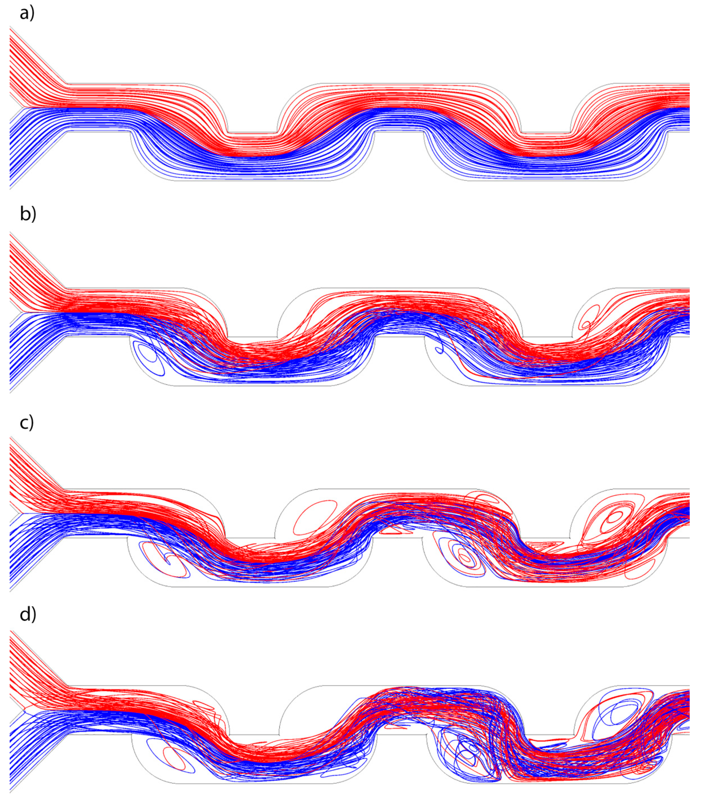
The flow behavior in the micromixer was investigated using streamlines. The flows from different inlets were marked with different colors: red and blue. As a sample, a rectangular grid on inlets with spacing 0.005 (0.08 mm) was chosen.
By stratified flow, due to domination of viscous forces in relation to the inertia forces, no vortices form and all streamlines are strictly parallel. The diffusion is the main mass-transfer process and convective mixing is absent. Consequently, a distinct interface between two flows can be clearly seen in the middle of the channel; for example at a Reynolds number of Re = 2.6 (Figure 5a). The streamlines are uniformly distributed for all cross-sections, therefore the absence of only small stagnation zones in the cells can be stated. It was found that the volume flow rate does not affect the streamlines within the stratified flow regime if Re < 2.6.
Starting from Re = 13, the flow regime can be defined as vortex flow (according to Figure 6). This causes an increase of the interface area between species and reduces the diffusion length. In Figure 5b, there is an example of weak vortex flow with relatively small vortex formations. Size and form of the vortices depend on the Dean number, i.e., Reynolds number in case of the same geometry. The larger the Reynolds number, the higher the amplitude of vortices.
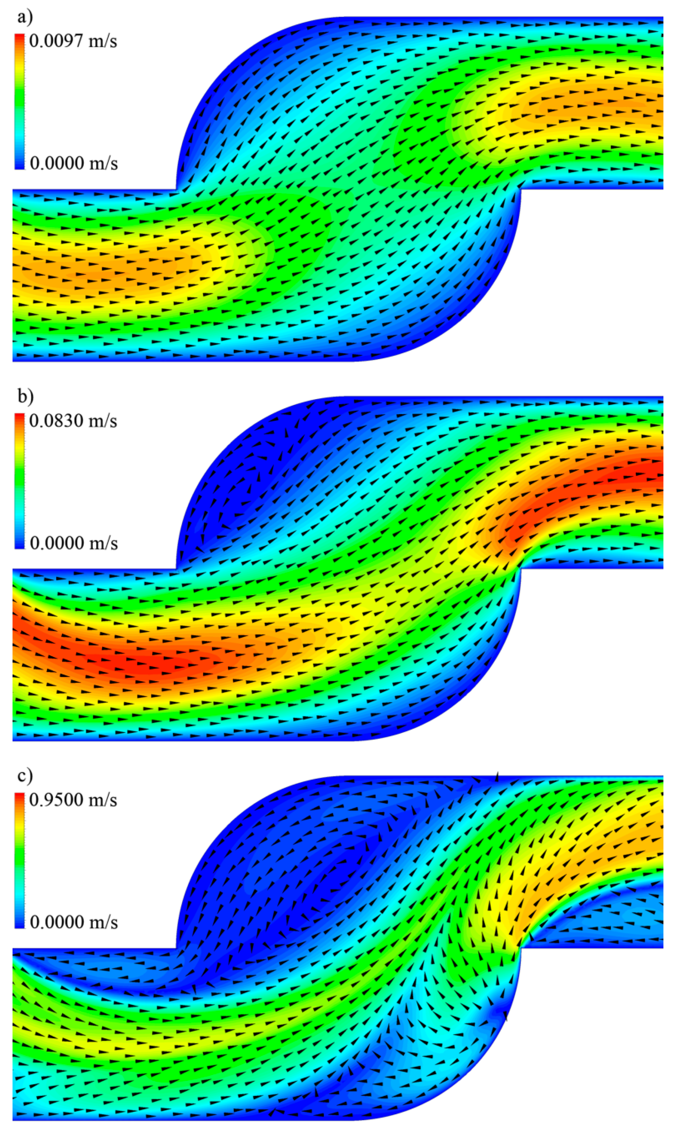
For the purpose of detection of stagnation zones, normalized velocity vectors (black arrowheads) and velocity contours for the symmetry plane for the second meander element are represented in Figure 7. At Re = 2.6 (Figure 7a) there are no recirculations. In Figure 7b, the velocity field and vector field at Re = 156 are shown. A stagnation zone is located directly after the sharp bend. The velocity magnitude in this area is almost zero and velocity vectors also indicate recirculation areas. By increasing the Reynolds number to Re = 259 (Figure 7c) the stagnation zone with recirculations has an increased area. The second smaller recirculation zone is located after the meander element in the place of transition to the rounded channel. The position of stagnation zones corresponds with the result, obtained in the same micromixer by Schwolow et al. using Diazo Coupling reaction [24]. The recirculation effect is also reported in some articles related to the zig-zag (or similar) form of the channel [19,32]. In addition, it was shown by Lee and Kwon [33] that the consecutive recirculation zones are responsible for the mass-transfer rating. The efficiency of recirculation was discussed by Shaker et al. [34] for some different geometries of microchannels and the presence of such zones was reported as intensification of the mixing process in comparison with a straight channel under the same conditions.
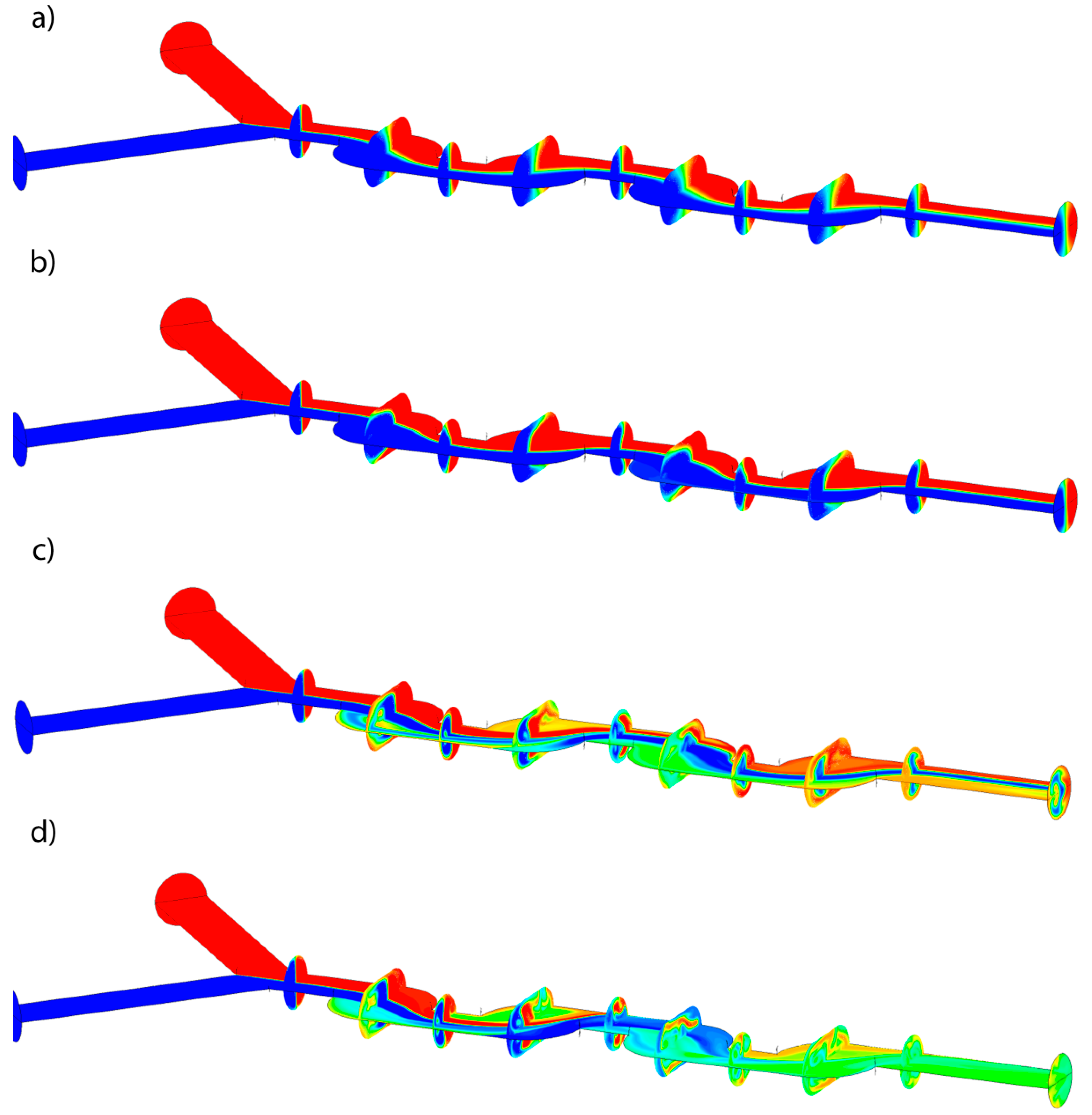
The distribution of concentration field is shown in Figure 6. The red and blue colors indicate two different species in the micromixer. The green color shows the ideal mixed flow: by Re = 2.6 (Figure 6a), the interface between species at the outlet is vertical. In the case of Re = 26 (Figure 6b), the Dean vortices appear, resulting in an increased interfacial area. Absolute qualitative different forms of the interface can be noticed by Re = 156 and Re = 259 (Figure 6d,c). Due to large recirculation and an extremely large magnitude of secondary flows, an enhanced mixing acceleration effect can be observed.
Moreover, it is shown that an asymmetrically formed channel provides greater effect than a symmetrical one. This can be explained by the presence of high quantity of curvatures, through which the flow has to pass and therefore increase the vorticity of the flow.

3.2. Mixing Index

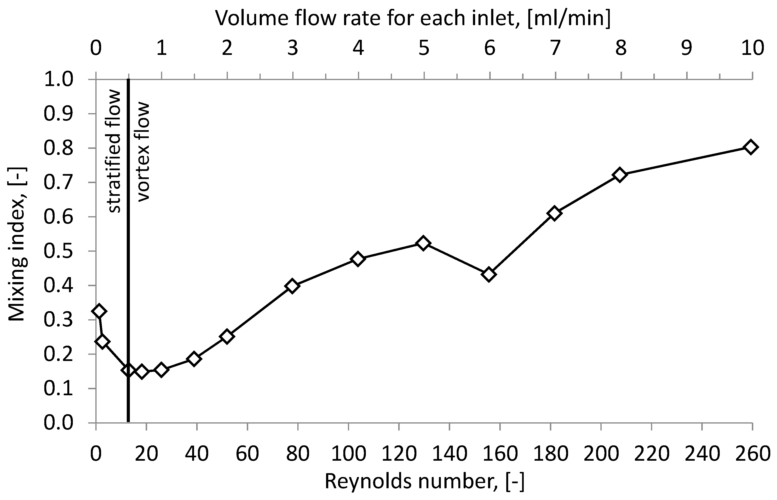
In order to investigate a mixing process in detail, the mixing index should be analyzed. In Figure 8, the dependency of the Reynolds number and the average mixing index within the outlet plane is indicated.
The lowest mixing index value is observed by Re = 13. This value divides the whole diagram into two parts, which indicates different flow regimes: stratified and vortex. Within the stratified flow regime, the mixing process obeys Fick’s law and depends on the mixing time. The mixing quality shrinks to 1 as the volume flow rate is reduced due to a squaring of the mixing time. If the volume flow rate is between Q = 0.5 mL/min and Q = 1 mL/min, the decreasing residence time is compensated by the increasing convective influence on the mixing. Consequently, the flat may be observed with the value IM = 0.15. It can be assumed that the convective mixing term in the micromixer plays a significant role, starting from Q = 1 mL/min when its role exceeds the diffusive term. As a result, the degree of mixing grows for an increasing volume flow rate.
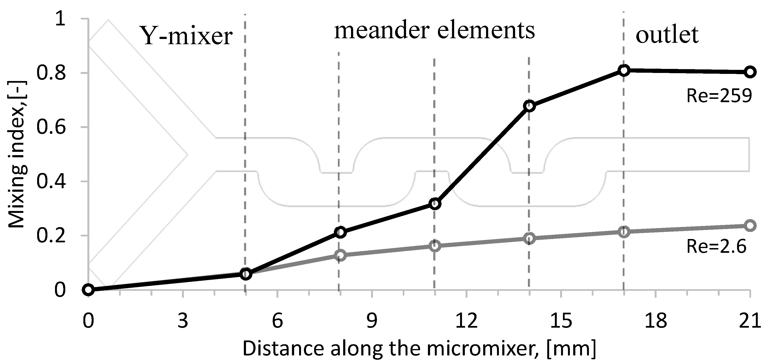
To understand the entire mixing process, the micromixer was geometrically divided into six different zones: the Y-mixer, four meander elements and the outlet channel. These zones are shown with borders as vertical dashed lines in Figure 9, and for each border the mixing degree was calculated for both stratified (Q = 0.1 mL/min) and vortex flow (Q = 10 mL/min). The results obtained show how the mixing changed along the micromixer for Q = 0.1 mL/min and Q = 10 mL/min. In the Y-mixer, there is no significant difference, but in the cells the degree of mixing increases significantly and reaches the value of IM = 0.8 for vortex flow. This indicates that the influence of the meander elements on mixing is actually only under the vortex flow regime. For the stratified flow the increase in mixing index is linear depending on the mixing time and reaches 0.2 at the outlet. At the same time the vortex flow allows for a mixing index of 0.8 for Q = 10 mL/min. Moreover, the mixing time is 100 times smaller in comparison with Q = 0.1 mL/min. This indicates the greater effectiveness of the vortex flow in comparison with the stratified flow.

3.3. Pressure Drop

The pressure drop Δ p is the loss of energy of the flow that occurs due to viscous forces. In general, in the field of laminar flow the dependency between the pressure drop and the Reynolds number (or the volume flow rate) is linear because of the Hagen-Poiseuille equation:
Δ p     Q .
However, if there is any vortex structure in the flow the above mentioned dependence becomes a square law [35].
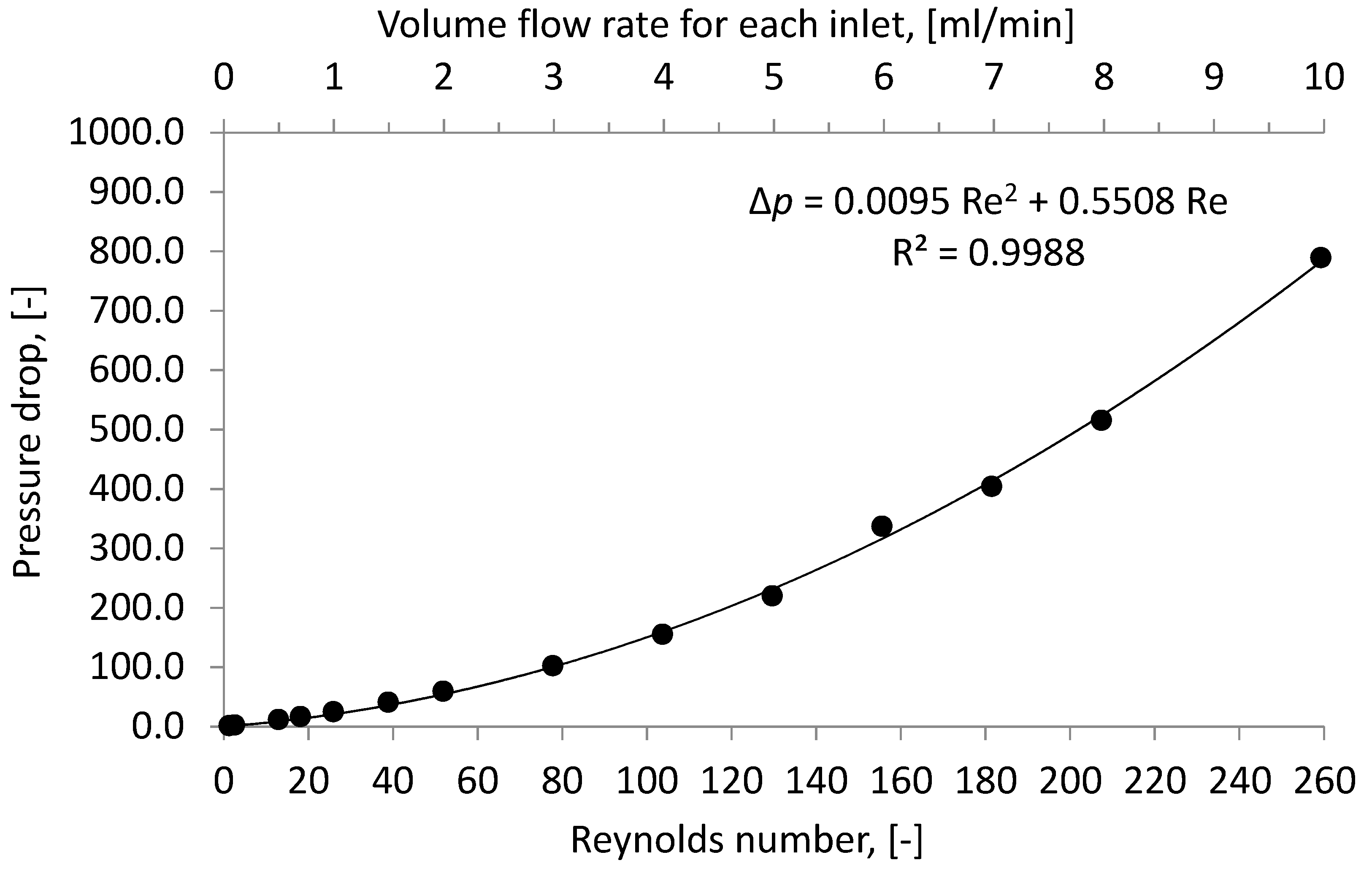
Using the CFD simulation, values of pressure drop were calculated for different volume flow rates (Figure 10).
The square dependence can be approximated as given by:
∆p = aRe2 + bRe
where a —is the quadratic coefficient, which is related to energy dissipated via chaotic advection, and b —the linear coefficient, which takes into account laminar flow wall friction. The form of the equation is similar to the Darcy-Weisbach equation, but it also includes a linear term. The pressure losses in each meander element of the micromixer in the case of Re = 2.6 and Re = 26 are constant and equal; 0.31 Pa and 3.71 Pa, respectively. By Re = 259, the value of the pressure loss in each mixing element varies from 155 to 212 Pa.
In comparison with a micromixer with a relationship between the radius of the circular element and the characteristic length of the channel between elements ratio: w/d = 1/8 [28], the studied micromixer has approximately a 10 times smaller pressure drop at the same Reynolds number and similar mixing index.
The mixing cost and mixing energy cost were calculated for the chicanes micromixer at different volume flow rates (Table 1) [36,37,38,39]. The highest mixing cost was obtained at low volume flow rates. Mixing cost decreases at increasing Reynolds number. This indicates that the higher flow rates lead to higher pressure drop inside the micromixer and the intensity of mixing rises within the chicanes channel due to mixing intensification. Therefore, an overall reduction of mixing costs and mixing energy costs can be observed.
Mixing costs for different micromixers at Reynolds number of 50 are presented in Table 2. The chicanes micromixer stands out among other micromixers which consist of a straight channel and a mixing head with a simple geometry [40]. The serpentine micromixers with the T-joint and tangentially aligned inputs from [41] are much effective compared to T and Y-micromixer with the straight channel. The serpentine micromixers have lower mixing costs than the chicanes micromixer, because of higher pressure losses due to right-angle geometry, which leads to a moderate intensification of the mixing. The further increasing of the channel complexity, as shown for serpentine 3D splitting and recombination-type (SAR) micromixers [42,43], causes higher energy dissipation and pressure drops up to 40 kPa at Reynolds number of 50. The generated saddle-shaped flow structure promotes chaotic advection and complete mixing at the micromixer outlet. Together with the extremely high pressure drop it provides low mixing costs, which are two orders of magnitude lower than the mixing costs of the serpentine micromixer.

3.4. Verification

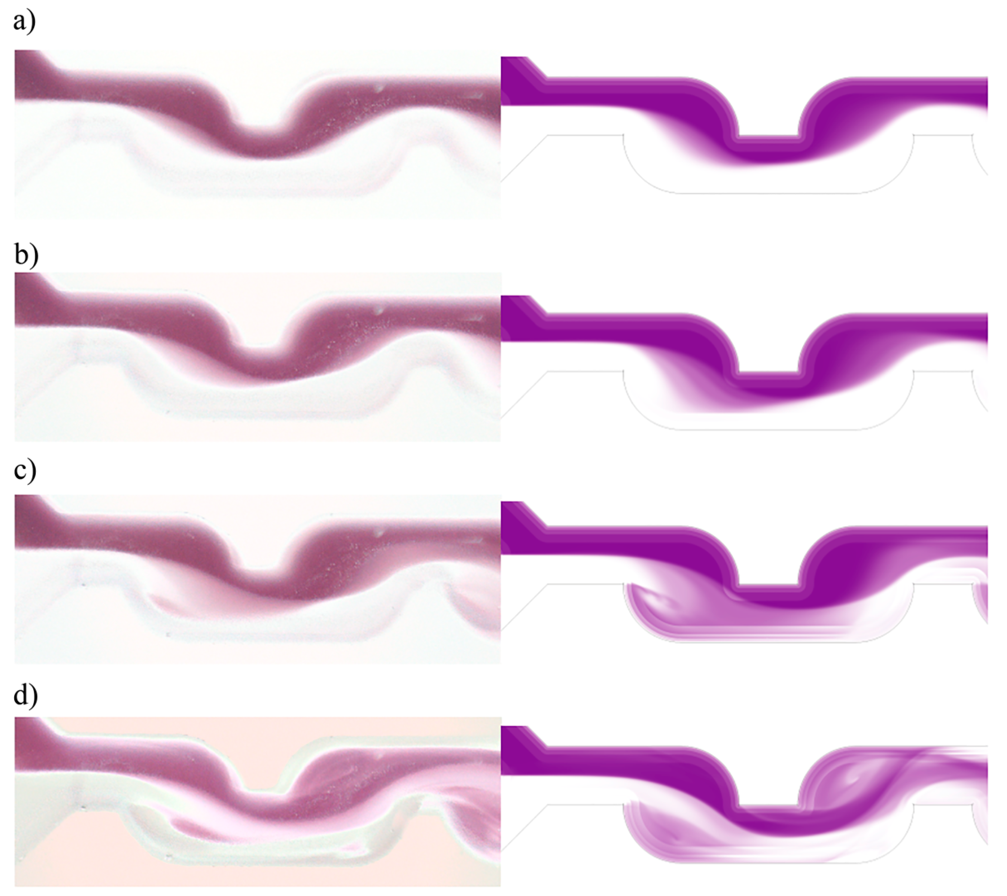
In this section, the experimental results were compared with simulation results. The simulation figures were obtained using a volume rendering tool in CFD-Post software. All points with mass fraction were divided into 10 semi-transparent slices according to the experimental pictures. Figure 11 shows the comparison between experimental results (left side) and simulation results (right side).
In general, in the case of stratified flow (Re = 13) there are no vortices and the interface between species is distinct. The small area of color gradient can be explained using a small “bend” of the flow due to the curvature of the flow direction after its entrance into the meander element. This vortex structure is growing together with increasing Reynolds numbers. In the case of Re = 78 and Re = 260, the vortex structure becomes qualitatively different due to the formation of the recirculation area directly after the extension.
It is conspicuous, that the interface between species of both the experimental and simulation results matches in all cases. Thus, it can be assumed that the simulation results generally agree with the experimental ones. The deviation between the simulation and the experimental results can be explained due to the inaccuracy of the micromixer production, i.e., differences between the real geometrical model of the micromixer and ideal geometrical model.

4. Conclusions

In the present study, the micromixer with a chicane mixing channel structure was investigated using a CFD simulation for volume flow rates of 0.05 mL/min ≤ Q ≤ 10 mL/min, and through experiments. Experimental results showed positive similarities with the numerical results. Based on the numerical results, the stratified and vertical flow regimes were identified. The stratified flow has strictly parallel streamlines and negligible stagnation zones. The mixing process takes place only in the interface between the species and is driven only by diffusion. The lowest mixing index value (IM = 0.15) is observed between Q = 0.5 mL/min and Q = 1 mL/min. It can be assumed then, that the geometric structure of microchannels with chicane mixing geometry is not utilized in the case of stratified flow. Additionally, the vortical flow regime shows significant advantages, such as forming vortex structures: recirculation and swirling, which is shown using streamlines. The convective mixing increases the interfacial area dramatically and therefore there is an essential gain in mixing. The increase of volume flow rate provides the increase of the mixing index. When volume flow rate is Q = 10 mL/min, the mixing index reaches the value IM = 0.8 after four cells. Furthermore, the pressure drop was investigated using CFD simulations. A square dependence of pressure drop vs volume flow rate was shown, which was due to the vertical structure of the flow.
Mixing costs for different micromixers at Reynolds number of 50 were calculated. The serpentine micromixers with the T-joint have lower mixing costs than the chicanes micromixer, because of drastically higher pressure losses due to right-angle geometry. The generated saddle-shaped flow structure in the serpentine SAR micromixers promotes chaotic advection and extremely high pressure drop, which provide much lower mixing costs than in the chicanes micromixer.

Author Contributions

Methodology, validation, investigation, visualization V.K.; conceptualization, methodology, validation, administration, writing—review and editing, E.B.; conceptualization, methodology, scientific discussions, supervision, funding acquisition, W.R.

Funding

This study was supported by the Erasmus Mundus Action 2 Programme of the European Union and by the Ministry of Education and Science of the Russian Federation, grant number No. 10.3444.2017/ПЧ.

Acknowledgments

The computations were performed on a Bull HPC Cluster Taurus at the Center for Information Services and High Performance Computing (ZIH) at TU Dresden. The authors thank Yulenets from the St. Petersburg State Institute of Technology (Technical University) for his helpful discussions.

Conflicts of Interest

The authors declare no conflict of interest.

Appendix A

Table A1. Calculation of grid convergence index at 1 mL/min according to [31,44].
ParameterFine GridNormal GridCoarse Grid
Total number of Cells23.2 × 1069.6 × 1064.0 × 106
Representative Grid Size8.29 × 10−611.06 × 10−614.76 × 10⁻⁶
Mixing Index0.150.180.21
Grid refinement Factor1.331.34-
Apparent Order 0.97--
Extrapolated Value0.08--
Error Estimate0.14--
Extrapolated Relative Error0.82--
Fine-grid Convergence Index0.56--

References

  1. Reschetilowski, W. (Ed.) Principles of microprocess technology. In Microreactors in Preparative Chemistry: Practical Aspects in Bioprocessing, Nanotechnology, Catalysis and More; Wiley-VCH: Weinheim, Germany, 2013; pp. 1–12. ISBN 978-3-527-33282-3. [Google Scholar]
  2. Dencic, I.; Hessel, V. Industrial Microreactor Process Development up to Production. In Microreactors in Organic Synthesis and Catalysis, 2nd ed.; Wirth, T., Ed.; Wiley-VCH: Weinheim, Germany, 2013; pp. 211–275. ISBN 978-3-527-33299-1. [Google Scholar]
  3. Nguyen, N. (Ed.) Micromixers based on chaotic advection. In Micromixers: Fundamentals, Design and Fabrication, 2nd ed.; William Andrew: Oxford, UK, 2012; pp. 195–236. ISBN 978-1-4377-3520-8. [Google Scholar]
  4. Capretto, L.; Cheng, W.; Hill, M.; Zhang, X. Micromixing Within Microfluidic Devices. Microfluid. Technol. Appl. 2011, 304, 27–68. [Google Scholar] [CrossRef]
  5. Kumar, V.; Paraschivoiu, M.; Nigam, K.D.P. Single-phase fluid flow and mixing in microchannels. Chem. Eng. Sci. 2011, 66, 1329–1373. [Google Scholar] [CrossRef]
  6. Pagliara, S.; Dettmer, S.L.; Keyser, U.F. Channel-facilitated diffusion boosted by particle binding at the channel entrance. Phys. Rev. Lett. 2014, 113, 048102. [Google Scholar] [CrossRef] [PubMed]
  7. Soleymani, A.; Kolehmainen, E.; Turunen, I. Numerical and experimental investigations of liquid mixing in T-type micromixers. Chem. Eng. J. 2008, 135, 219–228. [Google Scholar] [CrossRef]
  8. Löb, P.; Drese, K.S.; Hessel, V.; Hardt, S.; Hofmann, C.; Löwe, H.; Schenk, R.; Schönfeld, F.; Werner, B. Steering of Liquid Mixing Speed in Interdigital Micro Mixers—From Very Fast to Deliberately Slow Mixing. Chem. Eng. Technol. 2004, 27, 340–345. [Google Scholar] [CrossRef]
  9. Schonfeld, F.; Hessel, V.; Hofmann, C. An optimised split-and-recombine micro-mixer with uniform chaotic mixing. Lab Chip 2004, 4, 65–69. [Google Scholar] [CrossRef] [PubMed]
  10. Zhang, Z.; Zhao, P.; Xiao, G.; Lin, M.; Cao, X. Focusing-enhanced mixing in microfluidic channels. Biomicrofluidics 2008, 2, 14101. [Google Scholar] [CrossRef] [Green Version]
  11. Sudarsan, A.P.; Ugaz, V.M. Multivortex micromixing. Proc. Natl. Acad. Sci. USA 2006, 103, 7228–7233. [Google Scholar] [CrossRef] [Green Version]
  12. Bothe, D.; Sternich, C.; Warnecke, H.J. Fluid mixing in a T-shaped micro-mixer. Chem. Eng. Sci. 2006, 61, 2950–2958. [Google Scholar] [CrossRef] [Green Version]
  13. Dean, W.R. Note on the motion of fluid in curved pipes. Philos. Mag. Ser. 1927, 7, 208–223. [Google Scholar] [CrossRef]
  14. Dean, W.R. The streamline motion of fluid in a curved pipe. Philos. Mag. Ser. 1928, 7, 673–695. [Google Scholar] [CrossRef]
  15. Krupa, K.; Nunes, M.I.; Santos, R.J.; Bourne, J.R. Characterization of micromixing in T-jet mixers. Chem. Eng. Sci. 2014, 111, 48–55. [Google Scholar] [CrossRef]
  16. Gobby, D.; Angeli, P.; Gavriilidis, A. Mixing characteristics of T-type microfluidic mixers. J. Micromech. Microeng. 2001, 11, 126–132. [Google Scholar] [CrossRef]
  17. Li, P.; Cogswell, J.; Faghri, M. Design and test of a passive planar labyrinth micromixer for rapid fluid mixing. Sens. Actuators B 2012, 174, 126–132. [Google Scholar] [CrossRef]
  18. Stroock, A.D.; Dertinger, S.K.W.; Ajdari, A.; Mezic, I.; Stone, H.A.; Whitesid, G.M. Chaotic mixer for microchannels. Science 2002, 295, 647–651. [Google Scholar] [CrossRef] [PubMed]
  19. Mengeaud, V.; Josserand, J.; Girault, H.H. Mixing Simulation of a Zigzag Microchannel: Finite Element Simulations and Optical Study. Anal. Chem. 2002, 74, 4279–4286. [Google Scholar] [CrossRef] [PubMed]
  20. Bhagat, A.A.S.; Peterson, E.T.K.; Papautsky, I. A passive planar micromixer with obstructions for mixing at low Reynolds numbers. J. Micromech. Microeng. 2007, 17, 1017–1024. [Google Scholar] [CrossRef]
  21. Ziegenbalg, D.; Kompter, C.; Schönfeld, F.; Kralisch, D. Evaluation of different micromixers by CFD simulations for the anionic polymerisation of styrene. Green Process. Synth. 2012, 1, 211–214. [Google Scholar] [CrossRef]
  22. Borovinskaya, E.S.; Reshetilovskii, V.P. Microstructural Reactors: Concept, Development and Application. Russ. J. Appl. Chem. 2008, 81, 2211–2231. [Google Scholar] [CrossRef]
  23. Parsa, M.K.; Hormozi, F. Experimental and CFD modeling of fluid mixing in sinusoidal microchannels with different phase shift between side walls. J. Micromech. Microeng. 2014, 24, 065018. [Google Scholar] [CrossRef]
  24. Schwolow, S.; Hollmann, J.; Schenkel, B.; Röder, T. Application-Oriented Analysis of Mixing Performance in Microreactors. Org. Process Res. Dev. 2012, 16, 1513–1522. [Google Scholar] [CrossRef]
  25. Holvey, C.P.; Roberge, D.M.; Gottsponer, M.; Kockmann, N.; Macchi, A. Pressure drop and mixing in single phase microreactors: Simplified designs of micromixers. Chem. Eng. Process. 2011, 50, 1069–1075. [Google Scholar] [CrossRef]
  26. Alam, A.; Kim, K.Y. Mixing performance of a planar micromixer with circular chambers and crossing constriction channels. Sens. Actuators B Chem. 2013, 176, 639–652. [Google Scholar] [CrossRef]
  27. Schwarz, S.; Borovinskaya, E.S.; Reschetilowski, W. Base catalyzed ethanolysis of soybean oil in microreactors: Experiments and kinetic modeling. Chem. Eng. Sci. 2013, 104, 610–618. [Google Scholar] [CrossRef]
  28. Ansari, M.A.; Kim, K.-Y. A numerical study of mixing in a microchannel with circular mixing chambers. AIChE J. 2009, 55, 2217–2225. [Google Scholar] [CrossRef]
  29. Galletti, C.; Roudgar, M.; Brunazzi, E.; Mauri, R. Effect of inlet conditions on the engulfment pattern in a T-shaped micro-mixer. Chem. Eng. J. 2012, 185, 300–313. [Google Scholar] [CrossRef]
  30. Danckwerts, P.V. The Definition and Measurement of Some Characteristics of Mixtures. Appl. Sci. Res. Sect. A Mech. Heat Chem. Eng. Math. Methods 1952, 3, 279–296. [Google Scholar] [CrossRef]
  31. Celik, I.B.; Ghia, U.; Roache, P.J. Procedure for estimation and reporting of uncertainty due to discretization in CFD applications. J. Fluids Eng. 2008, 130. [Google Scholar] [CrossRef]
  32. Naher, S.; Orpen, D.; Brabazon, D.; Poulsen, C.R.; Morshed, M.M. Effect of micro-channel geometry on fluid flow and mixing. Simul. Model. Pract. Theory 2011, 19, 1088–1095. [Google Scholar] [CrossRef] [Green Version]
  33. Lee, J.; Kwon, S. Mixing efficiency of a multilamination micromixer with consecutive recirculation zones. Chem. Eng. Sci. 2009, 64, 1223–1231. [Google Scholar] [CrossRef]
  34. Shaker, M.; Ghaedamini, H.; Sasmito, A.P.; Kurnia, J.C.; Jangam, S.V.; Mujumdar, A.S. Numerical investigation of laminar mass transport enhancement in heterogeneous gaseous microreactors. Chem. Eng. Process. 2012, 54, 1–11. [Google Scholar] [CrossRef]
  35. Engler, M. Simulation, Design, and Analytical Modeling of Passive Convective Micromixers for Chemical Productions Purposes; Shaker Verlag GmbH: Aachen, Germany, 2006; pp. 1–15. ISBN 978-3832251390. [Google Scholar]
  36. Khozeymeh-Nezhad, H.; Niazmand, H. A double MRT-LBM for simulation of mixing in an active micromixer with rotationally oscillating stirrer in high Peclet number flows. Int. J. Heat Mass Transf. 2018, 122, 913–921. [Google Scholar] [CrossRef]
  37. Ortega-Casanova, J.; Lai, C.H. CFD study on laminar mixing at a very low Reynolds number by pitching and heaving a square cylinder. Comput. Fluids 2018, 168, 318–327. [Google Scholar] [CrossRef]
  38. Ortega-Casanova, J. Enhancing mixing at a very low Reynolds number by a heaving square cylinder. J. Fluids Struct. 2016, 65, 1–20. [Google Scholar] [CrossRef]
  39. Hsiao, K.; Wu, C.; Huang, Y. Fluid mixing in a microchannel with longitudinal vortex generators. Chem. Eng. J. 2013, 235, 27–36. [Google Scholar] [CrossRef]
  40. Sarkar, S.; Singh, K.K.; Shankar, V.; Shenoy, K.T. Numerical simulation of mixing at 1–1 and 1–2 microfluidic junctions. Chem. Eng. Process. Process Intensif. 2014, 85, 227–240. [Google Scholar] [CrossRef]
  41. Hossain, S.; Kim, K. Mixing Performance of a Serpentine Micromixer with Non-Aligned Inputs. Micromachines 2015, 6, 842–854. [Google Scholar] [CrossRef] [Green Version]
  42. Raza, W.; Hossain, S.; Kim, K. Effective mixing in a short serpentine split-and-recombination micromixer. Sens. Actuators B Chem. 2018, 258, 381–392. [Google Scholar] [CrossRef]
  43. Hossain, S.; Kim, K. Mixing analysis in a three-dimensional serpentine split-and-recombine micromixer. Chem. Eng. Res. Des. 2015, 100, 95–103. [Google Scholar] [CrossRef]
  44. Ortega-Casanova, J. Application of CFD on the optimization by response surface methodology of a micromixing unit and its use as a chemical microreactor. Chem. Eng. Process. Process Intensif. 2017, 117, 18–26. [Google Scholar] [CrossRef]
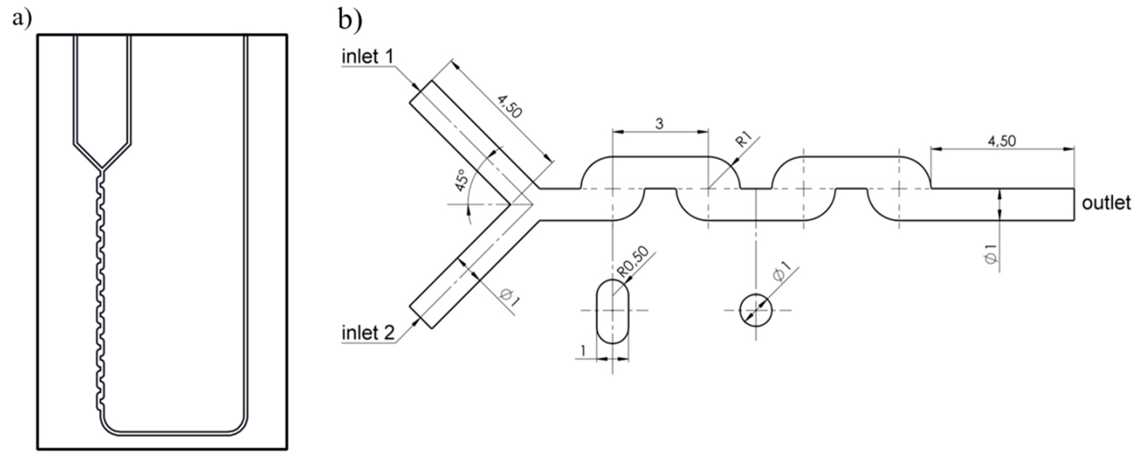
Figure 1. (a) Scheme of LTF-MS micromixer; (b) Geometrical model.
Applsci 08 02458 g001
Figure 2. Scheme of the experimental setup.
Applsci 08 02458 g002
Figure 3. Image post processing.
Applsci 08 02458 g003
Figure 4. Dependency of mixing index at the micromixer outlet compared with the number of grid cells (Re = 42.4).
Applsci 08 02458 g004
Figure 5. Simulated streamlines for different flow regimes: (a) stratified flow (Re = 2.6); (b) weak vortex flow (Re = 26); (c) vortex flow (Re = 156); and (d) vortex flow (Re = 259).
Applsci 08 02458 g005
Figure 6. Evolution of concentration field: (a) Re = 2.6; (b) Re = 26; (c) Re = 156; and (d) Re = 259.
Applsci 08 02458 g006
Figure 7. Simulated velocity magnitude field and normalized velocity vectors: (a) Re = 2.6; (b) Re = 156; and (c) Re = 259.
Applsci 08 02458 g007
Figure 8. Variations of the mixing index with the volume flow rate.
Applsci 08 02458 g008
Figure 9. Mixing index along length of the micromixer.
Applsci 08 02458 g009
Figure 10. Pressure drop by different Reynolds numbers.
Applsci 08 02458 g010
Figure 11. Comparison of experimental (left) and simulation results (right): (a) Re = 13; (b) Re = 26; (c) Re = 78; and (d) Re = 260.
Applsci 08 02458 g011
Table 1. Mixing cost and mixing energy cost for the chicanes micromixer at different volume flow rates.
Volume Flow RateReynolds NumberIntensity of MixingPressure DropMixing CostInput Power CoefficientMixing Energy Cost
mL/min--Pa1/Pa--
0.051.30.331.0730.3774,590.932295.11
0.12.60.242.1511.0413,598.50573.78
0.513.00.1511.341.35351.1522.95
0.718.20.1516.410.91174.4711.71
125.90.1524.750.6288.365.74
1.538.90.1940.800.4647.432.55
251.90.2559.100.4236.001.43
377.80.40102.100.3925.370.64
4103.70.48155.000.3117.110.36
5129.70.52219.700.2412.000.23
6155.60.43336.970.136.890.16
7181.50.61404.000.157.140.12
8207.50.72515.000.146.470.09
10259.30.80789.000.104.610.06
Table 2. Comparison of mixing cost of the chicanes micromixer with other micromixers without chicanes geometry.
MicromixerReynolds NumberPressure DropIntensity of MixingMixing CostSource
-Pa-1/Pa
Longitudinal vortex generators6410,0001.000.01[39]
Opposite T-junction50930.110.12[40]
45 Y-junction50940.130.14[40]
135 Y-junction50950.140.14[40]
cross T-junction50990.160.17[40]
Serpentine micromixer with simple T-joint inputs4510,0000.350.20[41]
Serpentine micromixer with tangentially aligned inputs4512,0000.440.26[41]
3D serpentine crisscross SAR micromixer5040,0001.000.003[42]
3D serpentine SAR micromixer5040,0000.900.002[43]
Chicanes micromixer52590.250.42Present study