1. Introduction
Optical code-division multiple access (OCDMA) [
1,
2,
3] has drawn much attention as a promising competitor against time-division multiple access (TDMA) [
4] and wavelength-division multiple access (WDMA) [
5]. In OCDMA, users are allowed to asynchronously access the network with a high degree of information capacity, security, and processing gain. Other features are the flexibility of adding and removing users in the network and the transparency in different modulation formats. Based on the above characteristics, OCDMA has been employed in a wide range of optical applications, such as metro area networks (MANs) [
6], radio-of-fiber (RoF) [
7], passive optical networks (PONs) [
8], and optical fiber sensors [
9]. Each active user expresses the information bits as a unique code sequence. The correlation properties among OCDMA codes guarantee the correct extraction of user information from the multiplexed signals. However, multiuser interference (MUI) [
10] induced from the overlapping signals in a shared channel degrades the network quality.
Spectral-amplitude coding (SAC) improves the practicality of OCDMA by reducing the MUI effect [
11,
12,
13]. Due to the support of asynchronous communications, SAC simplifies system complexity by releasing the requirement of timing recovery. The optical spectrum is encoded by the code sequences with a fixed cross-correlation value. Combining the code property with the complementary subtraction algorithm forms an MUI cancellation scheme known as balanced detection [
14,
15]. At the receiver, the multiplexed coded signals, including the target and the interference users, are correlated with the local code. The data bit “1” from the target user can be interpreted as a high autocorrelation peak between the local and the target code. The cross-correlation values between the local and the interference codes are eliminated by balanced detection. Therefore, the user data in SAC–OCDMA systems can be extracted without the presence of MUI. However, the principal limitation on system performance is phase-induced intensity noise (PIIN) [
16]. PIIN comes from the incoherency of broadband light sources (BLSs) adopted in SAC systems for encoding. The variance of PIIN is positively correlated with user number and bit-rate. Increasing the transmission speed results in a large noise power that causes the network to fail to reach a designated floor of bit-error rate (BER).
Although employing balanced detection eliminates MUI, it is not effective in suppressing PIIN. As PIIN is proportional to the square of the received power, launching a large-intensity light source cannot mitigate this effect. Modifying the decoder structure has become one of the leading solutions to noise suppression in OCDMA [
17,
18,
19]. In Reference [
20], rather than balanced detection with two photodiodes, a multiphotodiode scheme was proposed. PIIN mitigation is achieved by dividing the received power into multiple photodiodes to lower the detected power. The authors of [
21] studied a new receiver structure known as direct detection, where a single photodiode measures the nonoverlapping chips in the target code.
Recently, many studies have addressed the interference mitigation problem for wireless CDMA systems [
22,
23,
24]. The authors of Reference [
25] employed chip-interleaving strategies in the transmitter of direct-sequence (DS) CDMA to suppress interference. The interleaving information is based on the feedback bit sequences traveling through the loop from the receiver to the transmitter. Two uplink power control algorithms, open- and closed-loop control were proposed to limit the interference in femto cell networks [
26]. The open- and the closed-schemes varied the transmitted user power to meet the requirement of the interference threshold between femto cell users, and the threshold at the macro cell base station (BS), respectively. In [
27], a game theoretical approach was adopted for adjusting the user power to minimize the interference power in wireless CDMA networks. The scenarios of power allocation were modeled as a game structure with convex pricing.
As the MUI cancellation problem has been investigated in detail for wireless CDMA, such schemes have also been introduced in OCDMA networks [
28]. Due to the non-negativity of the optical intensity, a modified parallel interference cancellation (PIC) is proposed to suit this inherent property of the optical signals [
29]. Compared to the existing balanced detection, these studies yield better performance to some extent, but some bottlenecks still require further investigation—for example, the limited user numbers, the ineffectiveness in performance improvement, and the time delay resulting from the processing of the electrical signals.
In this paper, we investigate an intelligently structured receiver for noise suppression, as well as high-speed transmissions. The proposed architecture employs array waveguide grating (AWG), an optical switch, and a balanced detector to build an interference mitigation scheme known as recursive interference cancellation (RIC). There are several stages in RIC, with each of them performing interference estimations and regenerations. At each stage, the signal of an interference user is removed by subtracting the estimated interference term from the received multiplexed signals. Before detecting the data bit of the target user, the signals from interference users are gradually removed through the consecutive stages. PIIN variance is a function of user number and bit-rate and increases with these two variables. Therefore, by reducing the number of interference users, the network is allowed to transmit signals with a higher bit-rate for a given noise level.
Compared to SIC and PIC, the proposed receiver scheme has several advantages. First, instead of MUI, we investigate the function of noise suppression, which has been rarely investigated in the existing interference cancelation schemes before. Second, most noise suppression methods in OCDMA are employed for BER reduction, while we investigate the applications to high-speed transmissions. Third, rather than requiring multiple decoders in PIC or SIC, the proposed RIC reduces system complexity, using a single structure to identify all interference users. Finally, as MUI cancellation is performed in the optical domain, RIC has the potential to solve the latency of signal processing in the electrical components.
The remainder of this paper is organized as follows. In
Section 2, the proposed mechanism of MUI cancellation in a SAC–OCDMA network is described. In
Section 3, the hardware implementation of the proposed receiver is investigated, together with software simulations to verify its effectiveness. In
Section 4, numerical simulations are conducted to quantify the bit-rate increment achieved by MUI elimination and noise suppression.
Section 5 presents a brief conclusion.
2. MUI Cancellation Algorithm of the Proposed SAC Receiver
For an OCDMA system with
K active users, the receiver performs MUI elimination
K − 1 times to remove
K − 1 interference users. Assuming the
Kth user is the target user, the
ith interference user is canceled at the
ith stage, where 1 ≦
I ≦
K − 1. At each stage, the receiver executes MUI estimation and mitigation, which are performed by the spectral decoder and recoder, respectively. We define
Ci and
di as the signature code and transmitted bit of the
ith interference user, respectively. At the
ith stage, the received multiplexed OCDMA signal
Ri is defined as follows:
where
CK and
dK are the signature code and the transmitted bit of the target user, respectively.
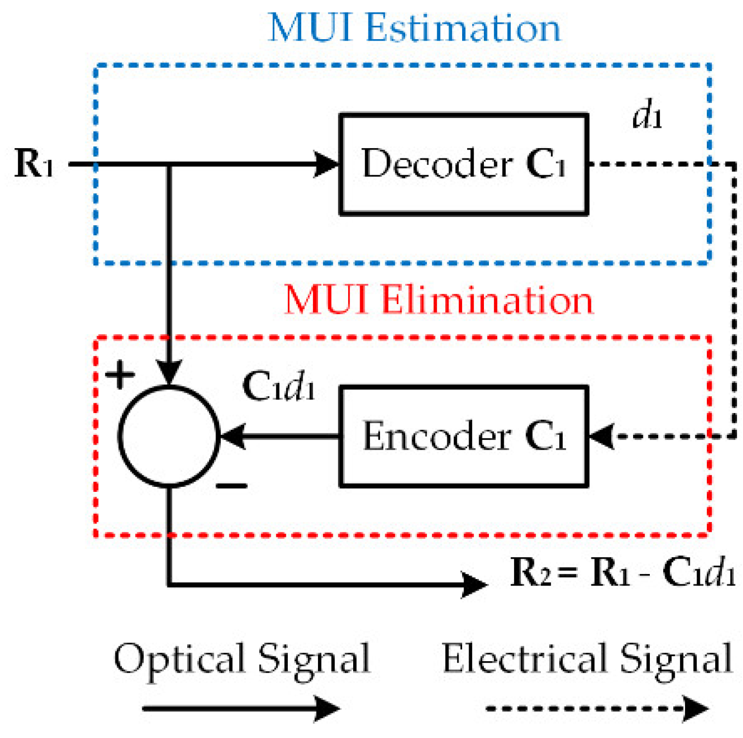
Figure 1 shows the relative phases of the MUI estimation and mitigation at the 1st stage of the proposed receiver. First,
d1 is detected by sending
R1 to decoder
C1, and it is re-encoded with signature code
C1 to construct the 1st interference term
C1d1. For MUI mitigation,
C1d1 is subtracted from the received signal
R1, and the signal entering the 2nd stage is defined as
R2 =
R1 −
C1d1. In each round of interference estimation/elimination, MUI is partially removed. Similar procedures are repeated
K − 1 times until all
K − 1 interference users are eliminated. Finally, only the target signal is left, and
dK can be recovered by passing
CKdK through decoder
CK.
Next, we describe the detailed process of decoding interference bit
di based on balanced detection. In this system, SAC signals are generated by employing M-sequences codes as the user signatures [
24]. M-sequences codes are one of the quasiorthogonal codes that have been widely used in OCDMA networks with good correlation properties. The code characteristics can be interpreted as (
N,
ω,
λ) = [
N, (
N + 1)/2, (
N + 1)/4], where
N is the code length and
ω and
λ are the auto- and cross-correlation value, respectively. We introduce the correlation properties of M-sequence codes as follow:
and:
where ⊙ is the dot-product symbol and
is the 2’s complement of
Ci. Based on the correlation properties of Equations (2) and (3), the value of
d1 can be determined by the following equation of correlation subtraction:
From Equation (4), one can see the 1st interference term d1 is successfully estimated.
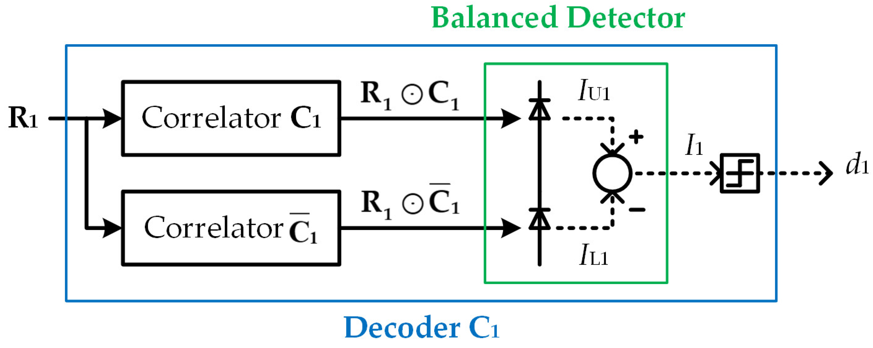
Figure 2 shows the decoder structure based on balanced detection for MUI estimation. In order to spectrally decode
d1, signature code
C1 is examined from the received signal
R1. The received signal is first split to the upper and the lower branch and then correlated with
C1 and
, respectively. The upper and the lower photodiode generate photocurrents
IU1 and
IL1, which are proportional to the correlation energy
R1⊙
C1 and
R1⊙
. The photocurrent
I1 at the output of the balanced detector is derived from the subtraction of
IU1 −
IL1, which is expressed as follows:
where
R is the responsivity of the photodiodes and
PL is the light source power. Based on Equation (5),
I1 is compared with the midrange threshold to determine the value of
d1.
Table 1 illustrates a numerical example of data transmissions of OCDMA signals. The network users can be classified into interference users, nonactive users, and target user. We assume that the 1st and the 2nd users are interferences and the 7th is the target. These three users send data bits of logic “1”, which are encoded with M-sequences codes of
C1 = {1, 1, 1, 0, 0, 1, 0},
C2 = {1, 1, 0, 0, 1, 0, 1}, and
C7 = {0, 1, 1, 1, 0, 0, 1}, respectively. The nonactive users send data bits of logical “0”, which are encoded with all-zero spectral chips. All coded spectral signals are multiplexed in a common fiber and broadcasted to all users. The received signal
R1 entering the 1st stage of the target user’s receiver is
C1 +
C2 +
C7 = {2, 3, 2, 1, 1, 1, 2}.
Table 2 illustrates the processes of MUI elimination for the proposed OCDMA receiver. At the 1st stage,
R1 is sent to decoder
C1, performing
R1⊙
C1 −
R1⊙
. The result of the correlation subtraction makes a decision about data bit
d1 = 1. This indicates that
C1 is included in the
R1 and the 1st user is an interference user. Then,
d1 is re-encoded with
C1 to regenerate interference term
C1d1 = {1, 1, 1, 0, 0, 1, 0}. By removing
C1d1 from
R1, the resultant signal is updated to
R2 =
R1 −
C1d1 = {1, 2, 1, 1, 1, 0, 2}.
At the 2nd stage, R2 is successively sent to decoder C2 with a similar operation to determine d2 = 1. The MUI of the 2nd user is identified and then cancelled by performing R2 − C2d2. For the next four stages, we find data bits d3, d4, d5, and d6 are all zero. Therefore, MUI cancellations are not performed in these rounds, and Ri is identical to Ri+1, for 3 ≦ i ≦ 5. At the 7th stage, all interferences are completely removed and R7 = {0, 1, 0, 1, 1, 1, 0} is arranged for the final decoding. As R7 matches the target code C7, we can decide data bit d7 = 1. This completes one full cycle of 7-stage MUI cancellation. The processes start over again when a new coded bit and other interferences arrive at the receiver.
3. Hardware Implementation of the Proposed OCDMA Receiver Based on Recursive Interference Cancellation
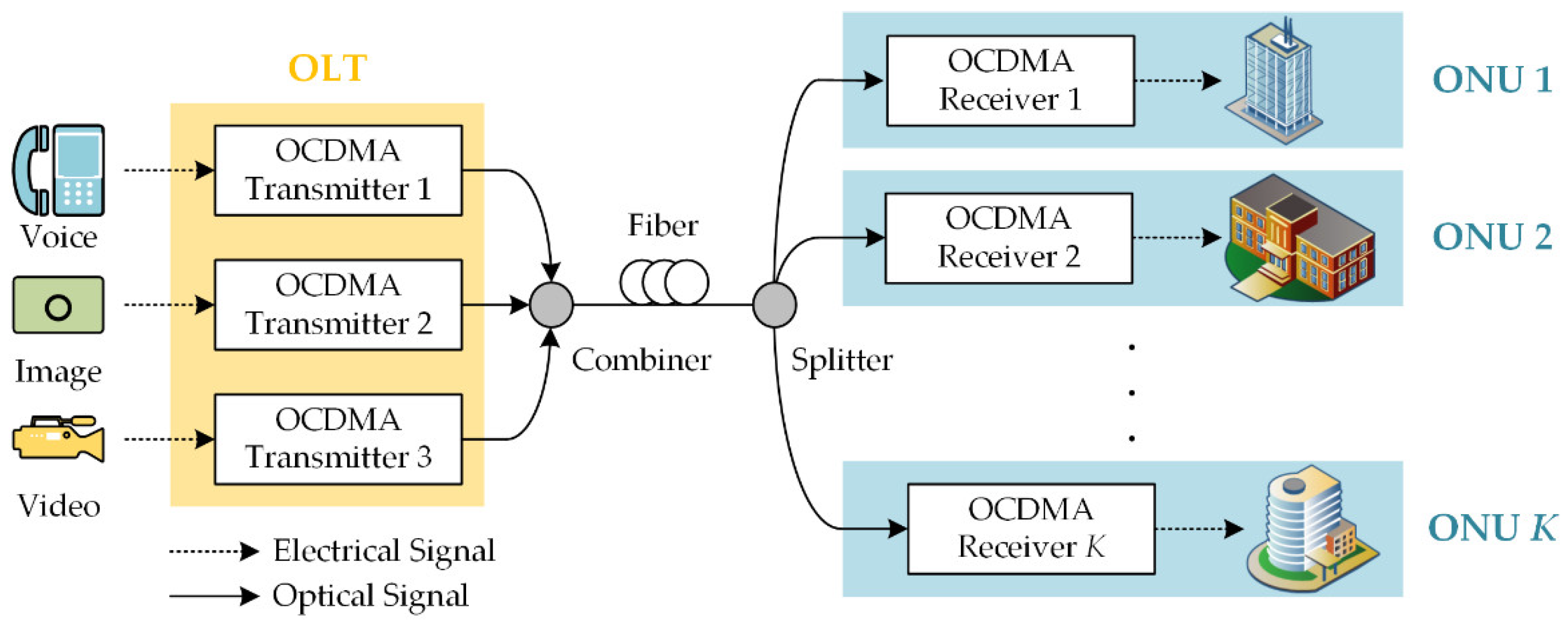
In this section, we investigate hardware implementation supporting the proposed algorithm of MUI cancellation. To demonstrate the RIC has the potential to be implemented in a practical communication scenario,
Figure 3 shows the PON topology based on OCDMA for downstream communications. PON supports various multimedia transmissions, such as voice, video, and image over a broadband optical access network. In optical line terminal (OLT), the received electrical data is firstly conveyed to optical pulses and then encoded with optical code by the OCDMA transmitter. The combined OCDMA signal is broadcast to several optical network units (ONUs) by splitting its power among all users. At ONU, the OCDMA receiver takes the inverse processes to decode and demodulate the received optical signals.
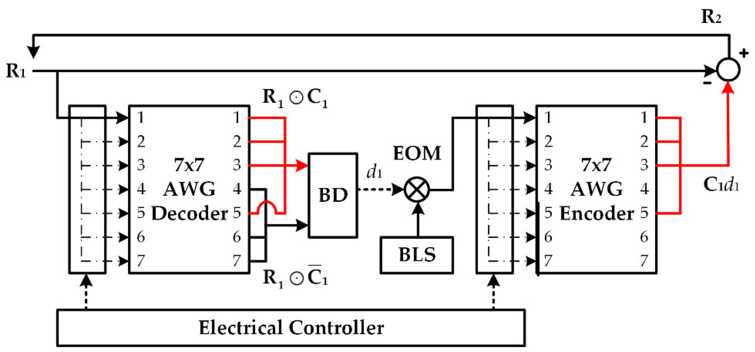
Figure 4 shows the receiver architecture designed with two array waveguide gratings (AWGs), an electrical controller, and a balanced detector. We use the example of user classification and M-sequence coded signals in
Table 1. OCDMA signals with the code length of 7 are encoded/decoded by the 7 × 7 AWGs. At the 1st stage, the received signal
R1 is sent to the 1st input port of the AWG encoder. The seven output signals are divided into two groups, with four signals in the first group and three in the second. The output ports of the signals (1, 2, 3, and 6) in the first group correspond to the chip positions of chip ones in code sequence
C1 = {1, 1, 1, 0, 0, 1, 0}; the numbers in the second (4, 5, and 7) correspond to the chip positions of chip zeros. Then, the first and the second grouped signals are transmitted to the upper and the lower branch of the balanced detector, respectively. The 1st interference bit
d1 is extracted by the result of correlation subtraction computing at the detector output.
As for interference regeneration, d1 is converted to the optical domain by an electrical–optical modulator (EOM) with a broadband light source (BLS). The modulated optical signal is sent to the 1st input port of the AWG encoder. The signals at the 1st, 2nd, 3rd, and 6th output ports are connected to generate interference term C1d1. Similar to the upper structure of the AWG decoder, the port selections are based on the chip positions of “1s” in C1. Then, C1d1 is removed from R1 by optical subtraction to complete the MUI elimination at the 1st stage.
To decode
d2,
R2 is propagated back to the AWG decoder via a fiber loop. An electrical controller changes the previous setting of path connection and sets up a new link to the 2nd input of the AWG. To generate
C2d2, the optical signal from the EOM enters the 2nd input port of the AWG encoder. Due to the cyclic-shift property of M-sequence codes and the AWG [
30],
Ci can be decoded by transmitting
Ri to the
ith input port of AWG decoder. Similarly,
Ci is generated by sending the light source to the
ith input port of AWG encoder. During the whole processes of MUI elimination, only the input connections of AWGs are adjusted by the electrical controller, while the output connections remain fixed. As the signals repeatedly propagate in a single receiver, this scheme is called recursive interference cancellation (RIC). RIC has the potential to solve the latency of signal processing in the electrical components, since it is executed in the optical domain.
As for the limitation of the proposed AWG-based receiver, it is suitable for decoding the OCDMA codes with cyclic-shift property, and the code length must match the AWG port number. Furthermore, for a conventional balanced detector, the received optical signal is directly down-converted to the electrical domain. RIC executes optical-electrical (O/E) and electrical-optical (E/O) conversions to identify the interference bit and re-generate the similar interference term at each stage. Employing an additional BLS in the receiver increases the network complexity and power consumption. Therefore, RIC removes the network MUI at the cost of moderate receiver complexity.
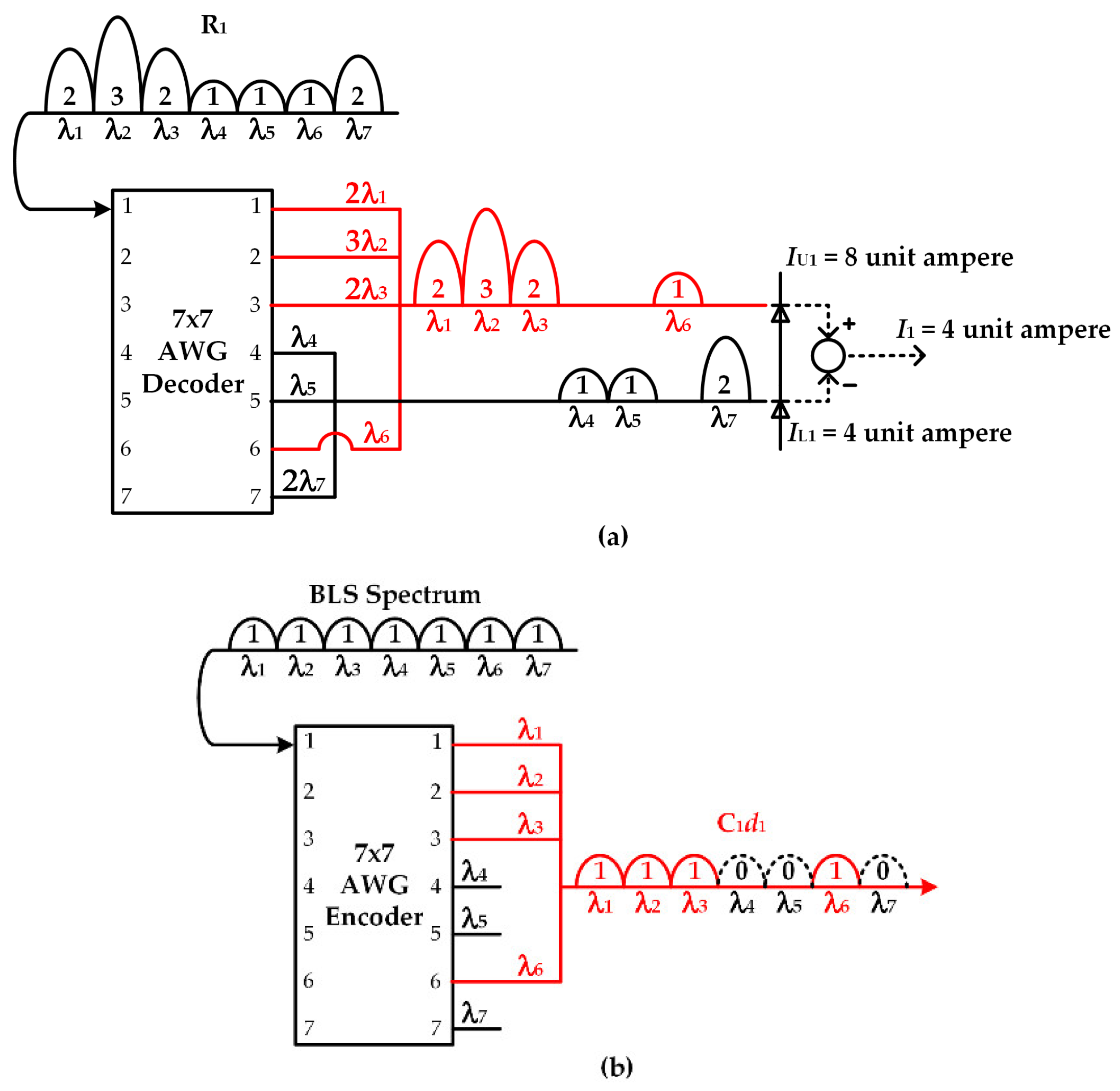
Figure 5 shows the decoding/encoding process of M-sequence code
C1. In the AWG decoder in
Figure 5a, wavelength components of λ
1, λ
2, λ
3, and λ
6 appearing at the 1st, 2nd, 3rd, and 6th output port are obtained by linking
R1 to the 1st input port. These components are collected at the upper branch to form an aggregated signal {2λ
1, 3λ
2, 2λ
3, λ
6}, which can be used for calculating
by summing the power on each wavelength (2 + 3 + 2 + 1 = 8). The wavelength signals shown at the lower branch {λ
4, λ
5, 2λ
7} are used for calculating
by summing their powers (1 + 1 + 2 = 4).
Figure 5b shows the AWG encoder designed for generating M-sequence codes. The spectrum of BLS is de-multiplexed into seven wavelengths. Signals of λ
1, λ
2, λ
3, and λ
6 at the AWG output ports are bound together to obtain
C1 = {1, 1, 1, 0, 0, 1, 0}. Similarly, we can also calculate
by connecting
R2 to the 2nd input port of the AWG decoder, as shown in
Figure 6a.
Figure 6b shows the encoding process of
C2 executed by switching the BLS spectrum to the 2nd input of the AWG encoder. Based on
Figure 5 and
Figure 6, seven M-sequences codes can be recognized/produced in a single device.
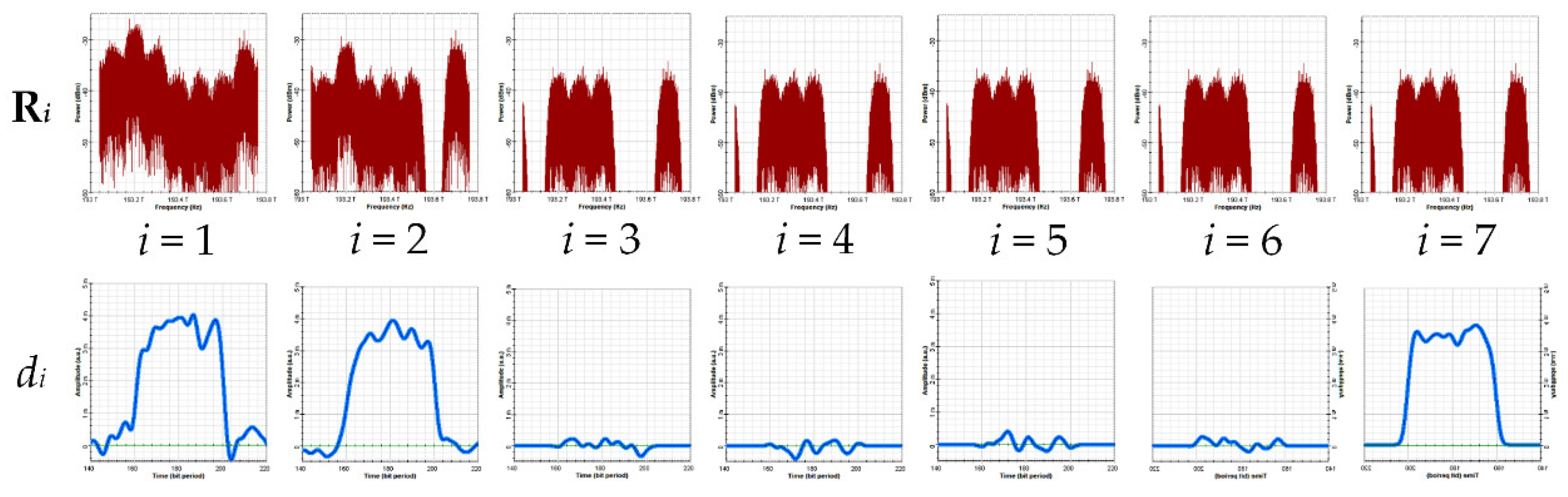
Next, we examine the effectiveness of the proposed system by conducting computer simulation using OptiSystem 7.0. The variations of signal waveforms in the processes of MUI estimation/elimination are demonstrated. The system structure for simulation is similar to that in
Figure 3. The center wavelength, bandwidth, and power of BLS are set to 193.4 THz, 0.7 THz, and 0 dB, respectively. The length of the bit sequence is 1024 and the bit rate is 1 GB/s. The AWG has seven channels, and each of them has a bandwidth of 0.8 THz. The power spectral density (PSD) of the OCDMA signals at the seven stages is presented in the first row of
Figure 7. Based on the results, the interference terms can be regenerated by the AWG encoder. It shows that MUI is canceled at the previous two stages, where the received spectrum
Ri matches the result of the numerical analysis in
Table 2. The second row in
Figure 7 presents the decoded data bits of the seven users. Although there are some slight variations in the waveforms, the amplitude for the decoded bit “1s” is significantly greater than that of the decoded bit “0s”. The results indicate that the data bits of the interference users and the target user can be successfully recognized by the AWG decoder. From the above two figures, the oscillations in the waveforms and the PSDs come from the intensity fluctuations of BLS. However, in a practical scenario, noise effects also have a great impact on the performance of OCDMA systems. Such issues are further investigated in
Section 4.
4. System Performance Analysis and Discussions
In this section, we analyze the OCDMA system with the proposed RIC scheme, considering the effect of PIIN and thermal noise. The main purpose is to quantify the improvement of system bit-rate benefiting from noise suppression. When a quantizer compares the photocurrent to its midrange threshold, an error may occur due to the signal variance. To calculate BER, we derive mathematical expressions for the mean and variance of the output signal at the balanced detector. We denote the signal mean as the photocurrent and the signal variance as the summation of thermal noise and PIIN. As the number of active users in a general OCDMA network is sufficiently large, the noise terms are approximate to the Gaussian distribution [
31]. BER is evaluated by calculating the signal-to-noise ratio (SNR) and using the complementary error function.
For simplicity without losing the generality, we firstly investigate the unit-stage scheme with a single balanced detector. For a practical BLS, there are oscillations on the PSD, which increase the complexity of system analysis. Therefore, we make several assumptions on the BLS properties. First, the BLS amplitude is constant over its bandwidth. Second, the power of the multiplexed signal detected by each user at the receiving end is the same. Finally, the optical pulses transmitted by each user are synchronized. The data bits
di of the interference/nonactive/active users can be determined from the photocurrent
Ii shown at the output of the balanced detector. For
di = 1,
Ii has previously been defined in Equation (5). When optical-to-electrical conversion is performed, the photocurrent variances are generated from the spontaneous emission of optical signals and the square-law detection of photodetectors. The signal variance 〈
i2〉 is written as follows:
where
denotes the variance of thermal noise; PIIN variance, which is a function of active user number
k, is denoted as
. According to the definitions in Reference [
25], these two noise terms are expressed as Equations (7) and (8):
where
STH is the PSD of thermal noise,
B is the noise-equivalent electrical bandwidth of the receiver, and
v is the encoded optical bandwidth. The symbol of
is denoted as the Kronecker product between two vectors [
32]. From Equations (5), (7), and (8), we can get the average SNR, which is shown as follows:
Note that when
di = 1,
Ii =
I for all
i. Using Gaussian approximation, the BER for a single-stage receiver with
k active users,
BER(
k), can be expressed as:
The primary difference between the unit-stage receiver and the proposed multistage receiver is the number of the received interference signals. Ideally, the conventional balanced detector receives
K − 1 interferences and one target signal, while the proposed scheme only receives the target one. However, in practical decoding, the noises lead the detector to misjudge interference bit “1s” as bit “0s”. The MUI cancellation is not executed in these stages, and less than
K − 1 interferences are removed from the received signal. As some interference signals remain, the effective user number
Keff in the signal for the final decoding is expressed as:
According to the Nyquist first theorem [
33], the receiver bandwidth must be larger than one half of the bit-rate to avoid intersymbol interference (ISI). Therefore, under a given SNR, the maximum signal bit-rate
Rb supported by the proposed receiver is:
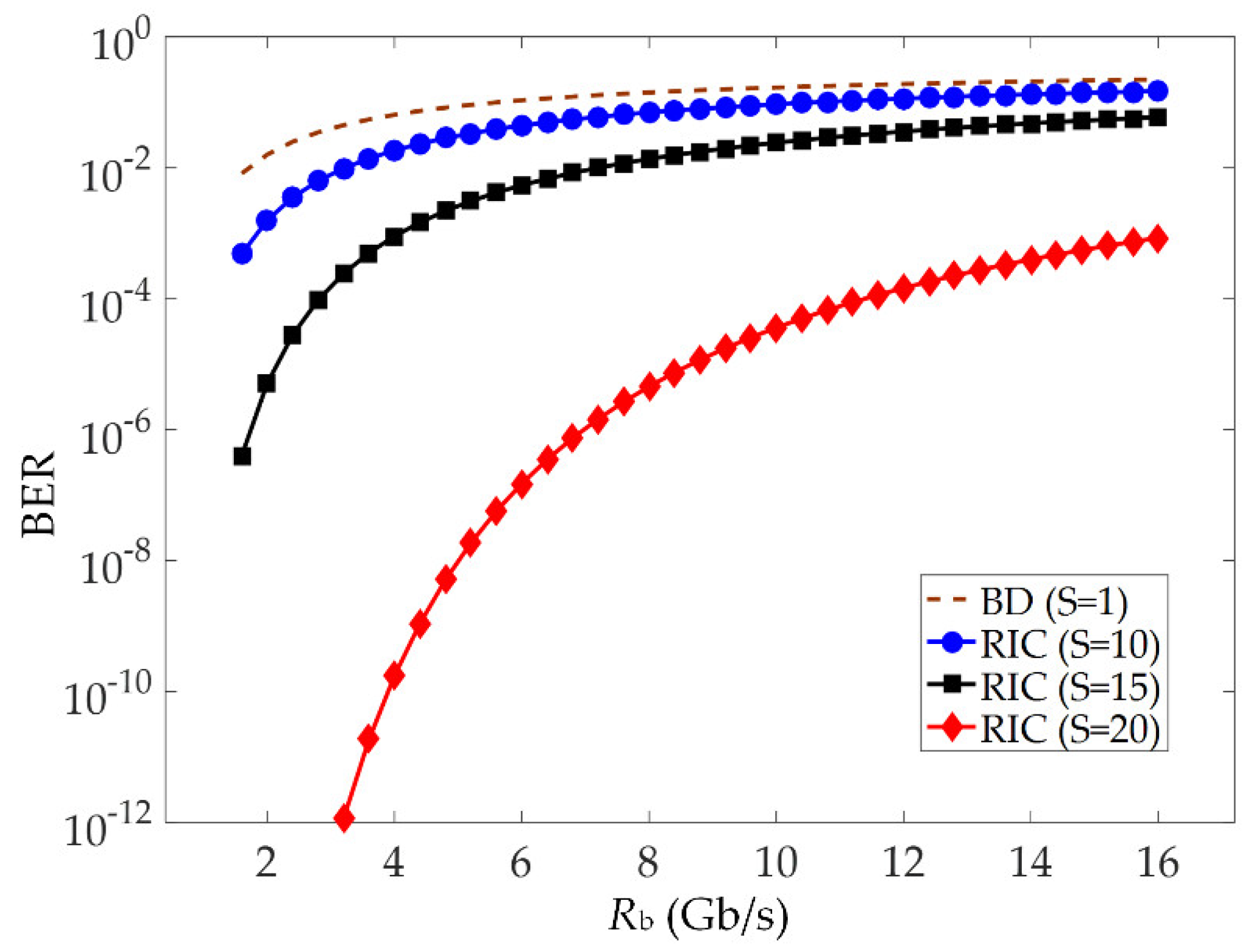
Figure 8 shows the relation between BER and the transmission rate of OCDMA users. The simulation parameters are listed as follow:
R = 0.81 A/W,
PL = −10 dBm,
N = 31,
STH = 1.632 × 10
−23 W/Hz, and
v = 3.75 THz. The number of active users
K is fixed to 20. The proposed RIC scheme with different stage numbers (
S = 10, 15, and 20) is analyzed, where the RIC with a unit stage (
S = 1) is equivalent to the conventional balanced detector. In previous publications related to SAC-OCDMA, balanced detector has been widely used for decoding as well as MAI eliminating [
11,
12,
13]. It can be found that the transmission rates
Rb supported by RIC are larger than the ones supported by the balanced detector. For PIIN variance, it is both dependent and positively related to
K and
Rb. Reducing the user number through RIC allows the network to send data bits with a higher speed under a given noise floor. In addition, as
S increases, more interference users are removed, and RIC obtains a faster data speed for the same BER.
Figure 9 shows the relationship between BER and the stage number
S with
K = 20. The results, which correspond to
Figure 8, indicate that BER lowers as
S increases for the same data bit-rate
Rb. Thus, RIC with a larger
S benefits from greater BER performance at the expense of executing additional procedures of interference user elimination. In addition, RIC with a smaller
Rb reveals a better performance when
S is fixed, as less noise power is allocated in the receiver bandwidth.
Splitting loss is another issue that should be considered in RIC. At each RIC stage, the received signal is divided into two portions with equal power, one for MUI estimation and the other for MUI elimination. This results in a 3-dB power penalty. When the stage number
S is small, the effect of splitting loss is not evident. However, when
S is further increased, the splitting loss may dominate BER due to the low received power.
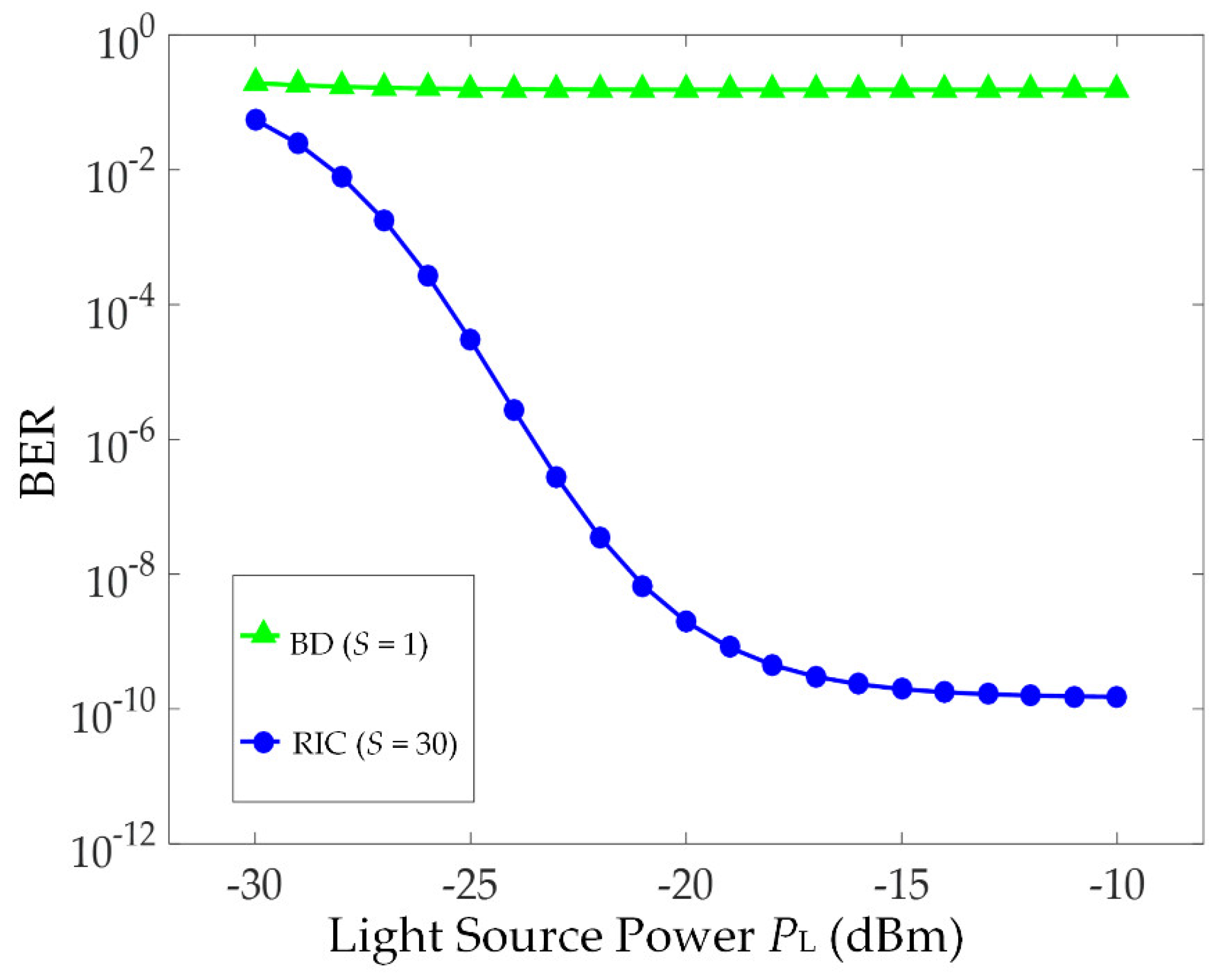
Figure 10 shows the relationship of BER and the received power
PL for active user number
K = 30 and bit-rate
Rb = 2 Gb/s. When
PL is relatively small, both schemes suffer from thermal noise and have a large BER. For the large values of
PL, where PIIN becomes dominant, the performance of RIC is better than that of the balanced detector. The performance improvement comes from the reduction of the interference users, resulting in less power contributing to PIIN. Based on this figure, although splitting loss degrades the BER performance of RIC, it can be compensated by launching a high-power light source or using an optical amplifier to recover the received power to its original level. As for the balanced detector, although it does not suffer from power loss, the BER is still large due to the high PIIN power contributed from the interference users.
In this section, we mainly discussed the factors associated with the proposed receiver, such as transmission data-rate Rb, receiver stage number S, and BER. We fixed the number of users K to more effectively assess the extent of data-rate improvement. As K also contributes to PIIN variance, a large K results in a large system BER. This effect is especially noticeable when the interference cancellations are executed at the initial stages, as the received signal contains many interference users. High-power noise induces a large probability that the value of the interference bit is misjudged, so the interference signals cannot be reconstructed correctly or eliminated. In the next RIC stage, these residual signals generating a relatively large amount of noise power still degrade the receiver performance. Based on Equation (11), effective user number Keff is increased with K, leading to the increased BER of the target signal. To keep the same BER for a large K, reducing the signal data-rate or increasing the receiver stage number is required.


