Article

Design and Experiment of a Novel Façade Cleaning Robot with a Biped Mechanism

by
Shunsuke Nansai
1,*,
Keichi Onodera
2,
Prabakaran Veerajagadheswar
3,
Mohan Rajesh Elara
4 and
Masami Iwase
2
1
Department of Advanced Machinery Engineering, School of Engineering, Tokyo Denki University, Tokyo 120-8551, Japan
2
Department of Advanced Multidisciplinary Engineering, Graduate School of Advanced Science and Technology, Tokyo Denki University, Tokyo 120-8551, Japan
3
SUTD-JTC I3 Center, Singapore University of Technology and Design, Singapore 487372, Singapore
4
Engineering Product Development Pillar, Singapore University of Technology and Design, Singapore 487372, Singapore
*
Author to whom correspondence should be addressed.
Appl. Sci. 2018, 8(12), 2398; https://doi.org/10.3390/app8122398
Submission received: 10 October 2018 / Revised: 18 November 2018 / Accepted: 19 November 2018 / Published: 26 November 2018
(This article belongs to the Special Issue Advanced Mobile Robotics)

Abstract

:
Façade cleaning in high-rise buildings has always been considered a hazardous task when carried out by labor forces. Even though numerous studies have focused on the development of glass façade cleaning systems, the available technologies in this domain are limited and their performances are broadly affected by the frames that connect the glass panels. These frames generally act as a barrier for the glass façade cleaning robots to cross over from one glass panel to another, which leads to a performance degradation in terms of area coverage. We present a new class of façade cleaning robot with a biped mechanism that is able overcome these obstacles to maximize its area coverage. The developed robot uses active suction cups to adhere to glass walls and adopts mechanical linkage to navigate the glass surface to perform cleaning. This research addresses the design challenges in realizing the developed robot. Its control system consists of inverse kinematics, a fifth polynomial interpolation, and sequential control. Experiments were conducted in a real scenario, and the results indicate that the developed robot achieves significantly higher coverage performance by overcoming both negative and positive obstacles in a glass panel.

1. Introduction

Robots have been advancing exponentially over the last three decades, moving beyond the traditional bounds of industrial applications into service missions and sharing social spaces with humans. Frey and Osborne have estimated that 47% of total US employment will be replaced by robots and/or artificial intelligence (AI) in the near future [1]. Early evidence points to significant improvements in productivity and safety over a number of service tasks that are dull, dirty, and/or dangerous [2]. Façade cleaning of high-rise buildings and skyscrapers offers enormous opportunities for the use of robots. In recent decades, skyscrapers such as Burj Khalifa [3,4,5,6] in Dubai and the Shanghai Tower [7,8,9] in Shanghai have been built as a result of improvements in construction technologies and processes. Even in such newfangled skyscrapers, the façades are generally cleaned by humans. In the case of some skyscrapers, including Burj Khalifa, equipment, such as gondolas, is not installed, and humans are employed to clean façades by hanging from a rope. The use of a manual workforce poses a high risk of fall, accidents, and even fatalities. Numerous incidences of accidents have been reported, even with the use of a gondola, in façade cleaning jobs. One such situation involved a gondola that lost control caused by a gust of wind at the Shanghai World Financial Center [10]. In another instance, a gondola became suspended in mid-air at a height of 240 m at the One World Trade Center in New York [11]. Robotic solutions offer enormous potential in significantly minimizing the risk to humans and improving productivity in façade cleaning jobs.
To overcome such issues, research on glass façade cleaning robots has been reported. For example, a series of Skycleaners, which are entirely driven by pneumatic actuators, has been developed to move and clean on the glass wall by utilizing vacuum suction cups [12,13]. The Skycleaner is installed with suction cups on both ends of the actuators in an X–Y stage, and these suction cups are connected to a vacuum pump [14]. Sun et al. developed a wall climbing robot with an X–Y stage mechanism as well as a rotational joint and demonstrated the effectiveness of the developed robot and the proposed strategies through field trials at both the City University of Hong Kong and the British Broadcasting Corporation (BBC) [15]. The efficacy and validity of the developed system has been demonstrated through a range of experiments [16]. Serbot AG, an industrial company in Switzerland, developed a wall and solar panel cleaning robot called GEKKO [17]. GEKKO is equipped with a vacuum suction cup crawler which rotates horizontally. The crawler has a semi-circular shape and has a straight line on one side and an arc line on the other side, through the use of which both linear and rotational motions are realized. By changing the number of brushes and crawlers, the developed robot can be manually reconfigured to adapt to different wall areas. Seo et al. developed ROPE RIDE [18]. ROPE RIDE enables one to climb up a vertical surface by utilizing a rope dropped down from the top of the building, two additional propeller thrusters are installed to securely adhere to the wall. A cleaning unit for a cleaning wall has been installed [19]. A new impedance control system has been proposed, and the effectiveness of the force control system to press brushes to the wall with a constant force has been shown through an experiment [20]. SIRIUS is a wall cleaning robot developed by Fraunhofer IFF, which is an industrial company in Germany [21,22,23,24]. SIRIUS realizes up-and-down motion by utilizing a crane installed on buildings for façade maintenance. It adheres to the wall by a suction system which locomotes like a linear actuator [25,26,27]. Ceplina et al. developed a wall climbing robot capable of spraying different cleaning and disinfecting liquids in hospital and clinic nursing environments assuming a full flat wall surface [28]. Akinfiev et al. developed a climbing cleaning robot hanging down from a crane. They prototyped the robot and demonstrated its effectiveness via experiments in real conditions [29]. The methods of the literature are effective and valid, as shown by the experimental results. Even though numerous studies in the literature have demonstrated the use of glass façade cleaning robots, conventional platforms experience a system failure with respect to area coverage, which degrades their full efficiency. One major factor in glass façade structures that affects the performances of façade cleaning systems is the frames that connect the two glass panels. These frames generally act as a barrier for glass façade cleaning robots to cross over from one glass panel to another, which leads to a performance degradation in terms of area coverage. One viable approach to overcome these difficulties in façade structures is to develop a façade cleaning system with a biped mechanism that can overcome these obstacles.
In the field of robotics, there have been several biped robots that have been reported in the literature for different application scenarios. Christian Ott et al. [30] proposed a novel biped walking machine for domestic service purpose. The proposed robot was designed as an experimental system for studying biped locomotion based on torque-controlled joints, and the experimental results were discussed by utilizing the scheme. In another work, Asiya M. Al-Busaidi developed a low-cost educational system to study and control a biped robot in real time [31]. The proposed system used MATLAB for visualization control. Arduino was used as a low-level controller to manage the walking gaits of the biped robot. Chen-Yuan Liu and Jhen-Cheng Wang developed a novel biped robot to obtain patient data from a Japanese patient office [32]. This particular study applied a three S-Curve model to analyze the acquired data. In addition, the analyzed information was used to foresee the development trend in the field of biped robot walking. Biped robots have been proposed for wall climbing and inspection purposes. The authors in Reference [33] proposed Climbot, which was developed based on the climbing patterns of leech worms. The presented robot was developed under a biped concept with five degrees of freedom and two special grippers as end effectors. Similarly, an urban reconnaissance climbing biped robot is presented in Reference [34]. The developed robot was under-actuated and made smaller in order to access confined spaces. The study discusses the evaluation process of the robot’s performance while navigating on inclined surfaces. In spite of the fact that numerous studies in the literature address biped robotics, they are largely limited to inspections and rescue applications. In addition, none of the previous work in biped robotics targets glass façade cleaning, which presents significant opportunities for research and development.
Our ultimate goal is to develop a glass façade cleaning robot using a biped mechanism capable of crossover from one glass panel to another without any difficulties, with an objective of maximizing its coverage area. In order to attain a working robotic system that can achieve a superior area coverage performance, we adopted a parallel linkage mechanism for the developed platform. The major challenges encountered during the development of our façade cleaning robot were its parallel linkage mechanism design, the assimilation of cleaning modules, and the translation of the theoretical design into a physical prototype. This paper summarizes all these aspects and concludes with experimental results that validate its ability to move from one glass pane to another.
This paper is organized as follows. The design and development of the biped façade cleaning robot satisfying the basis strategy is described in Section 2. Section 3 describes the design of the control system to locomote the developed biped robot on the glass surface. It is verified in Section 4 that the developed robot is capable of moving on the glass surface by utilizing the designed trajectory generator. Section 5 concludes this paper.

2. Development of Biped Robot

This section discusses the design challenges of the glass façade cleaning robot in terms of the glass cleaning process and area coverage. In particular, the abilities and tasks involved in glass façade cleaning are discussed, and ways in which to realize these abilities and tasks are proposed. Additionally, the hardware/software design challenges are described.

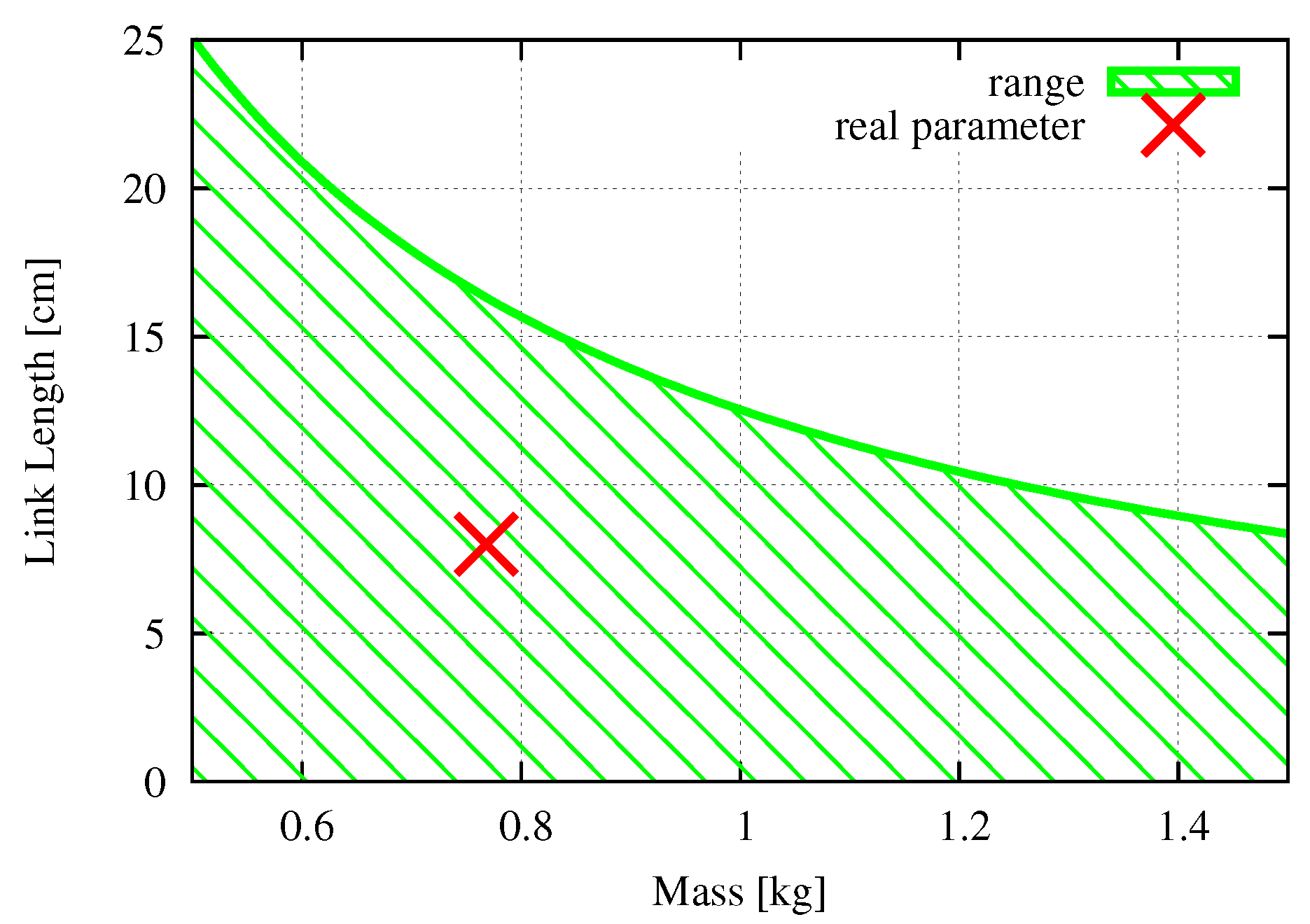
2.1. Design Challenges

In order to design an efficient façade cleaning robot, it is critical to (1) clean the window from top to bottom and (2) move the squeegee to track the scrubber, as shown in Figure 1. The design challenges involved in these key points are discussed in this section. The basic strategy is to resolve functions to achieve each key point as an individual design/control issue. Figure 2 shows a solution for window size and window shape for terrain adaptability. The solution is a biped system and consists of individual legs. The developed system extends its cleaning area and is controlled in a coordinated way. If the window shape is changed, it is able to adapt by extending the cleaning area of each individual leg. Additionally, Figure 2 shows the technique of the scrubber and the squeegee. The solution consists of a swarm control system to control the robots systematically. The swarm control system has high adaptability, as shown in Reference [35]. Patil et al. designed and implemented a UB swarm robot system consisting of five robots that are heterogeneous in sensory units, microcontroller, functionality, and size [36]. Our proposed swarm robot system consists of multiple biped robots equipped with a cleaning unit on each robot’s foot so that each robot can move from top to bottom and that the squeegee is installed next to the scrubber. Keeping the squeegee in contact with the glass surface during cleaning is a control issue of the robot. Additionally, cleaning in one direction is a transition plan of the developed robotic system as well. Thus, the challenges regarding the hardware and software are listed as follows:
Hardware Design Challenges
  • Development of the biped robot
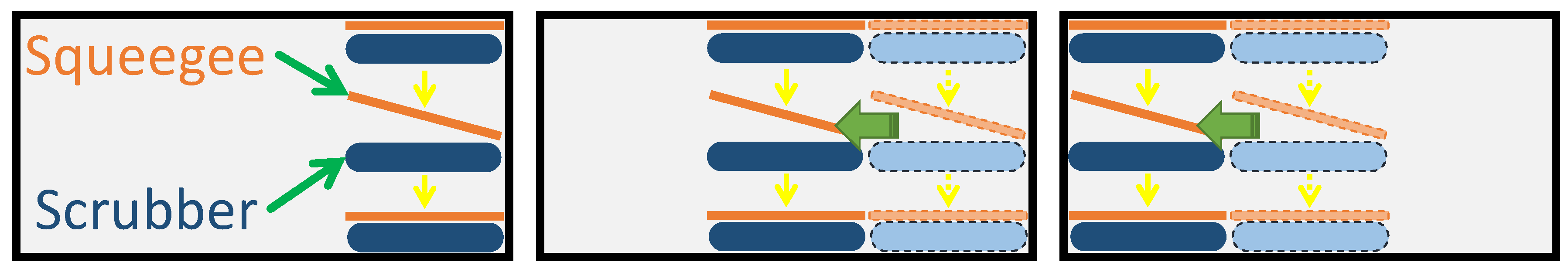
  • Development of a cleaning unit with the squeegee installed next to the scrubber
Software Design Challenges
  • Design of a control system capable of keeping both the scrubber and the squeegee in contact with the glass surface.
  • Design of a transition planner in order to clean in one direction

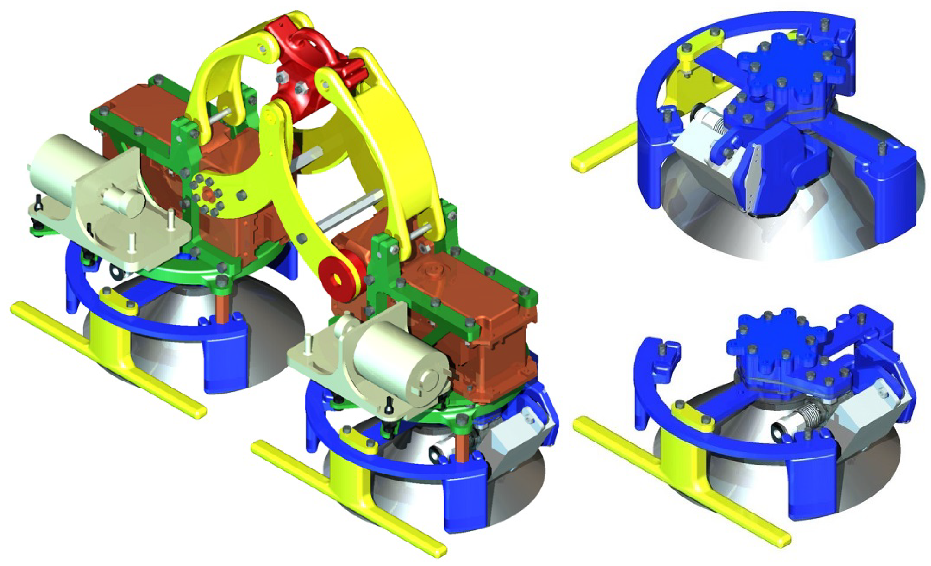
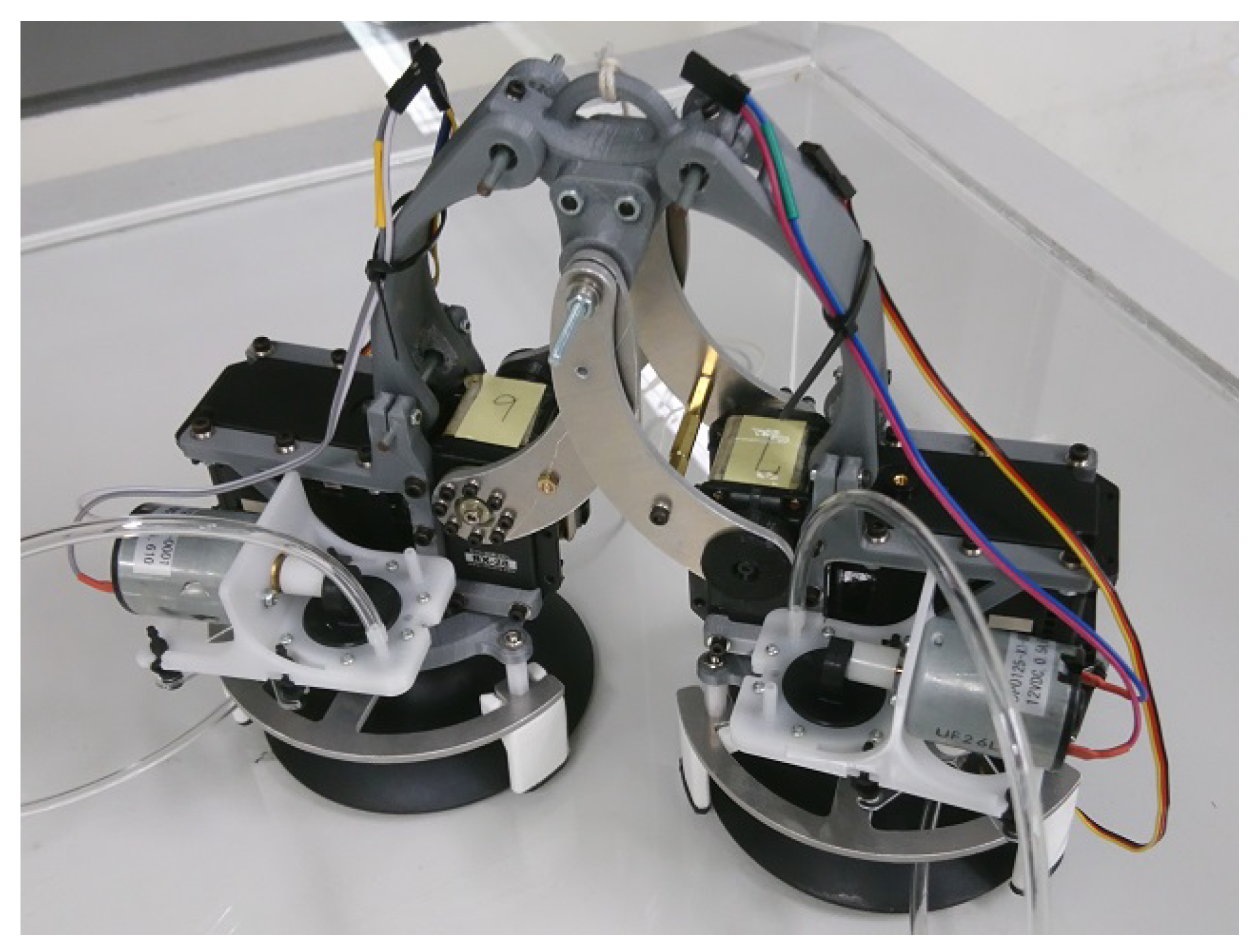
2.2. Biped Robot Design

Our strategy consisting of the biped mechanism and its control system has been described. In this section, specifications of the biped robot are analyzed quantitatively, and the development of the biped robot is shown.
Figure 3 is a CAD design of the biped robot. Each foot unit includes a cleaning unit, a suction cup, a vacuum pump, a seal mechanism, a valve to break vacuum, and servo motors for joint actuation. The morphology adopts a parallel linkage mechanism that keeps the foot unit of the robot and the glass surface parallel without any control system. That is, since the degree of freedom of the system is able to be decreased, the number of actuators for locomotion can also be decreased. Hence, adopting a parallel linkage mechanism provides an advantage in terms of weight saving. Weight saving is important because it allows one to decrease the amount of energy needed to maintain the robot’s weight. The area of both the adhesion/sealing mechanism and the driving mechanism are separated. This separation provides two advantages: the driving range in the rotational direction is extended, and maintenance is easy. Since only one attachment is required between each part, hardware updates in the future will be easy. Support parts, such as legs, can be installed onto the adhesion component. The support parts are pushed to the glass surface when the suction cup is in vacuum mode. This makes the robot robust against glass surfaces.
Figure 4 shows a schematic figure of the designed robot. The designed robotic system can be supposed as a simple two-link manipulator in a vertical plane on the arm. The origin is set on the center of the supporting leg, and the center of the idling leg ( x h , y h ) is
x h = l ( cos ϕ 1 + cos ϕ 2 ) + 2 d , y h = l ( sin ϕ 1 sin ϕ 2 )
where l [cm] and d [cm] represent the length of the link and the distance between the center of the foot to the joint, respectively. The angles of each link ϕ { 1 , 2 } are limited within Equation (2) as a result of the installation of the parallel linkage mechanism:
π 4 ϕ { 1 , 2 } 3 π 4 .
From Equation (1) within Equation (2), the theoretical movement range of the model is shown in Figure 5, where the actual movement range is smaller than Figure 5 due to collisions between the foot units. On the basis of Figure 5 and Equation (1), the robot is capable of moving ± 13.66 cm along the z axis and 22.54 cm along the x axis. In the case of the X–Y stage type, its movement range depends on one of its actuators. On the other hand, biped type robots, like the designed robot, can obtain enough movement range, even though one of the actuators is limited, since it mainly depends on its mechanism and link lengths.
The MX-106T and the RX-28 Dynamixel Robot Servo Actuator were adopted for driving actuators and were utilized as a base actuator and an arm actuator, respectively. Table 1 shows their specifications. Regarding the base actuator, the required torque τ b { 1 , 2 } [Nm] for driving is obtained by Equation (3), based on a simplified model shown in Figure 6.
τ b { 1 , 2 } m { 2 , 1 } g ( 2 d + l 1 cos ϕ 1 + l 2 cos ϕ 2 ) cos θ b { 1 , 2 } .
From Equation (3), if θ b { 1 , 2 } = ϕ { 1 , 2 } = 0 rad, the required torque becomes maximum. Since the stall torque of the servo motor is 8.4 Nm from Table 1, the driving torque is 2.8 Nm with a safety factor of 3. The relationship between link length and the weight of the foot unit is shown in Figure 7. From Figure 7, “×” highlighted in red represents the actual design parameter, and it satisfies Equation (3). Thus, MX-106T is able to generate enough driving torque as a base actuator. Regarding the base actuator, if θ b 1 = π / 2 , the required torque for driving τ { 1 , 2 } [Nm] is obtained by Equation (4), based on a simplified model shown in Figure 8.
τ { 1 , 2 } m { 1 , 2 } g l { 1 , 2 } sin ϕ { 1 , 2 } .
From Equation (4), if ϕ { 1 , 2 } = π / 2 rad, the required torque becomes maximum. Since the stall torque of the servo motor is 3.7 Nm from Table 1, the driving torque is 1.23 Nm with a safety factor of 3. The relationship between link length and the weight of the foot unit is shown in Figure 9. From Figure 9, “×” highlighted in red represents the actual design parameter, and it satisfies Equation (4). Thus, RX-28 is able to generate enough driving torque as a base actuator.
DP0125 is a vacuum pump, and its specification is shown in Table 2. A mechanical valve was installed on the switch vacuum and was controlled by an RC servo motor (shown in Table 1). A diagram of the vacuum system is shown in Figure 10. Since the diameter of the installed suction cup is 4 in. (approximately 10.16 cm), the suction force in the vertical situation W [N] is derived as follows:
W = C P 0.1 f , = 10.16 2 π × 33.3 × 0.1 × 1 8 = 134.987 ,
where C [cm 2 ], P [-kPa], and f represent the area of the suction cup, the vacuum pressure, and the safety factor, respectively, and the safety factor is generally set as 1/8 for the vertical situation. The weight of the developed robot is 1.483 kg and ensures that the designed vacuum system can secure itself to the vertical surface. Finally, the actual developed robot from CAD is shown in Figure 11.

3. Trajectory Generation

This section shows how the trajectories to locomote the developed robot individually were generated. Generally, biped robots alternately moves their left foot and then and right foot forward. However, such locomotion is not effective for glass façade cleaning, as discussed. In order to satisfy our basic strategy, the system locomotes one step at a time. We developed a gait to locomote a nest target step position indicated by an operator as a first step to full automation. A straight line basis gait should be generated (rather than a smooth gait as animals have) because when engaging/disengaging, the suction cup should approach the glass surface vertically to prevent involving the edge of the suction cup. Straight line basis foot trajectories were generated by utilizing a fifth polynomial interpolation and inverse kinematics. We assumed that the foot position would vary sequentially, and generated it utilizing sequential control.

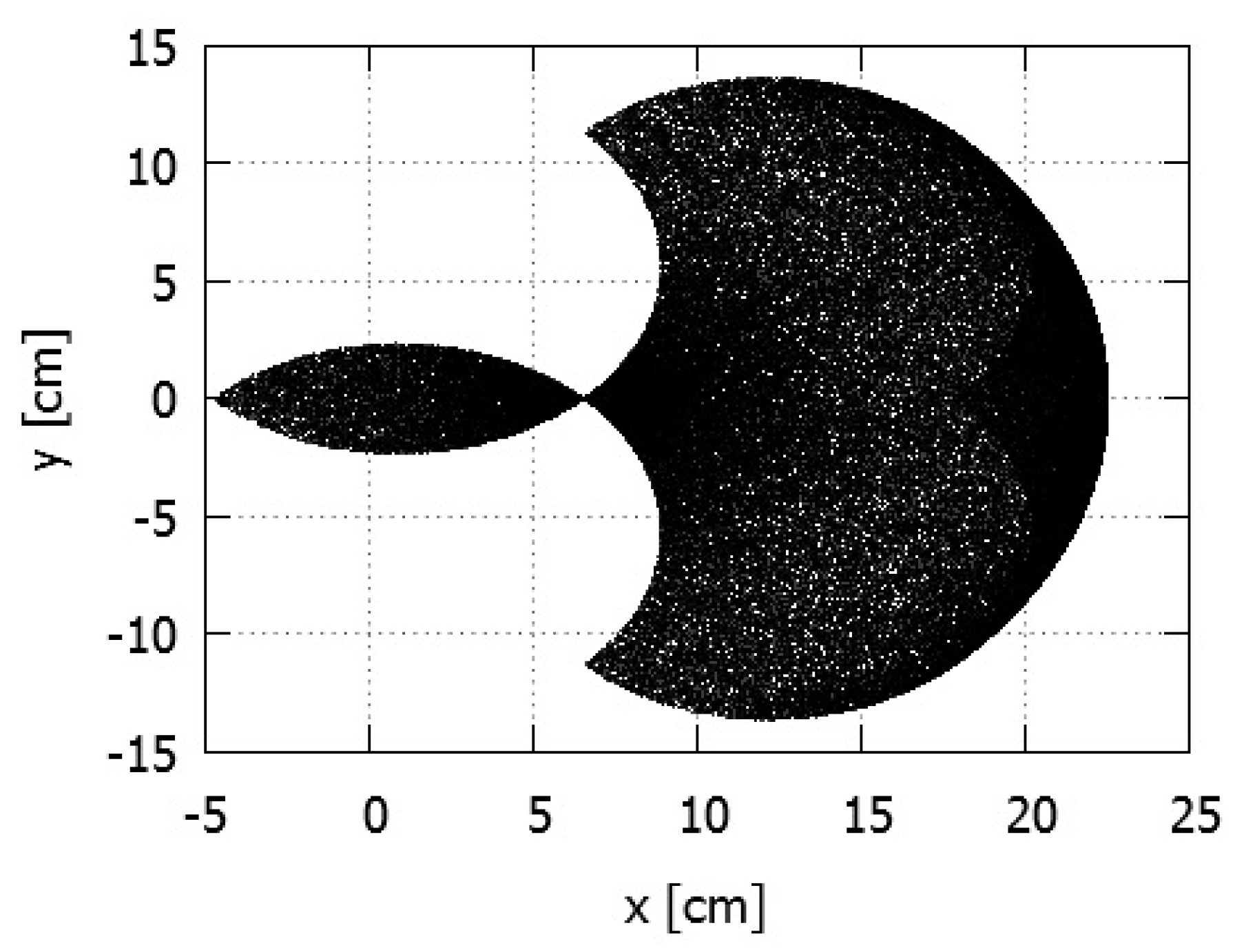
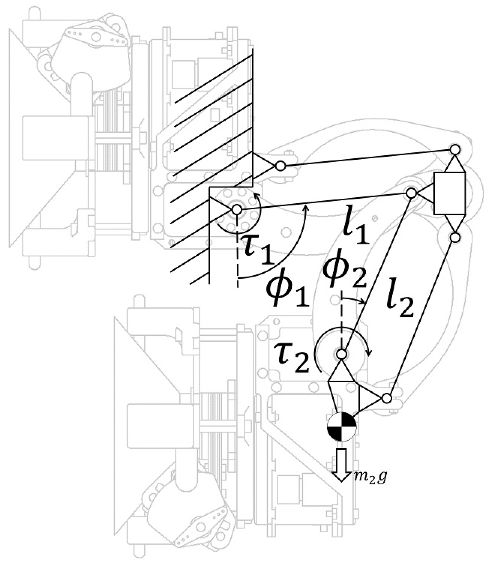
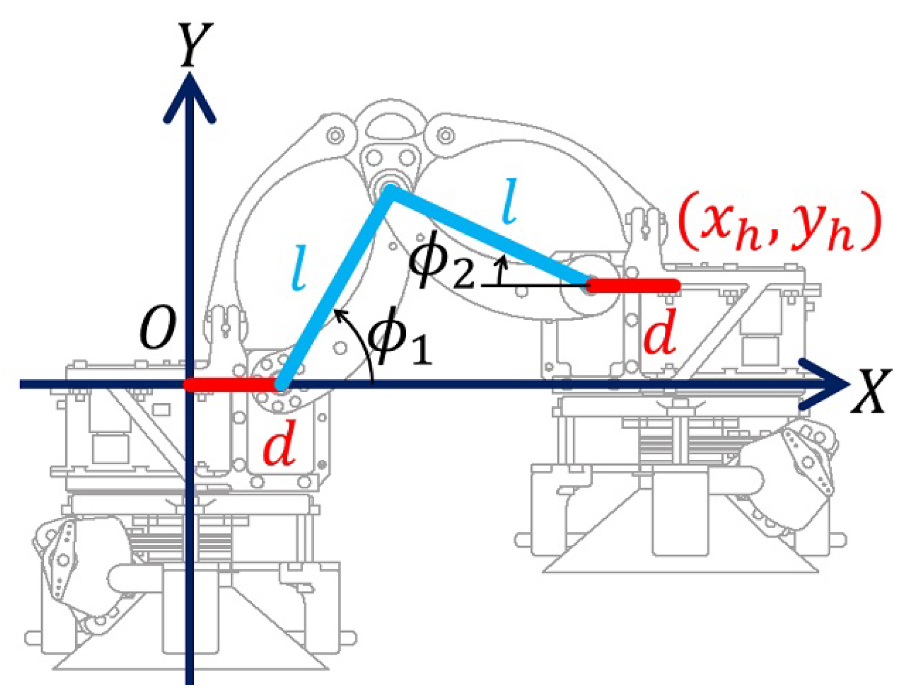
3.1. Inverse Kinematics

Firstly, target angles of each actuator, ϕ b 1 , ϕ b 2 , ϕ 1 , and ϕ 2 [rad], to realize target positions of the foot unit x r , y r , z r [cm] were formulated by utilizing inverse kinematics. Figure 12 and Table 3 show a schematic figure and parameters of the robot.
The target angles of the base actuators are
ϕ b { 1 , 2 } = tan 1 y r x r .
Moreover,
x d = x r 2 + y r 2 2 d , l 3 = x d 2 + z r 2 , ϕ 0 = tan 1 x d z r .
By cosine theorem,
ϕ 1 = cos 1 l 1 2 + l 3 2 l 2 2 2 l 1 l 3 , ϕ 2 = cos 1 l 2 2 + l 3 2 l 1 2 2 l 2 l 3 .
Thus, the target angles of each link θ { 1 , 2 } are
θ 1 = ϕ 0 + ϕ 1 ,
θ 2 = ϕ 0 + ϕ 2 .
The trajectories of each joint to move the system were derived by utilizing inverse kinematics formulated in Equations (5)–(7).

3.2. Fifth-Degree Polynomial Interpolation

A fifth-degree polynomial interpolation generates a smooth trajectory from a starting point of a gait to an ending point as the speed and the acceleration are represented as fourth and third degrees, respectively. Since all trajectory parameters (position, speed, and acceleration) in this approach are represented as a continuous function, load forces to the actuators can be decreased. Given these advantages, we used this technique for our generation of trajectories, an approach that has been successfully used previously in the community [37,38,39].
The trajectories of position x r ( t ) , y r ( t ) , z r ( t ) , speed x ˙ r ( t ) , y ˙ r ( t ) , z ˙ r ( t ) , and acceleration x ¨ r ( t ) , y ¨ r ( t ) , z ¨ r ( t ) in terms of time t are defined as follows:
{ x , y , z } r ( t ) = i = 0 5 a { x , y , z } i t i
{ x ˙ , y ˙ , z ˙ } r ( t ) = i = 1 5 i a { x , y , z } i t i 1
{ x ¨ , y ¨ , z ¨ } r ( t ) = i = 2 5 i ( i 1 ) a { x , y , z } i t i 2
where a i ( i = 0 , , 5 ) represents coefficients and these are derived from initial states and final states of a given gait. The initial and final states are defined as { x , y , z } s and { x , y , z } f , respectively. Let transformation time T [s] be constant. Using Equations (8)–(10), the initial states at the starting times, a 0 , a 1 , and a 2 , are derived as follows:
{ x , y , z } r ( 0 ) = a x , y , z 0 = { x , y , z } s
{ x ˙ , y ˙ , z ˙ } r ( 0 ) = a x , y , z 1 = { x ˙ , y ˙ , z ˙ } s = 0
{ x ¨ , y ¨ , z ¨ } r ( 0 ) = 2 a x , y , z 2 = { x ¨ , y ¨ , z ¨ } s = 0 .
Additionally, from the relation of the final states at the ending time, we have
{ x , y , z } r ( T ) = i = 0 5 a { x , y , z } i T i = { x , y , z } f
{ x ˙ , y ˙ , z ˙ } r ( T ) = i = 1 5 i a { x , y , z } i T i 1 = { x ˙ , y ˙ , z ˙ } f
{ x ¨ , y ¨ , z ¨ } r ( t ) = i = 2 5 i ( i 1 ) a { x , y , z } i t i 2 = { x ¨ , y ¨ , z ¨ } f .
By representing Equations (14)–(16) as a matrix form, a 3 , a 4 , and a 5 are derived as follows:
a { x , y , z } 5 a { x , y , z } 4 a { x , y , z } 3 = A 1 { x , y , z } f { x , y , z } s 0 0 ,
where
A = T 5 T 4 T 3 5 T 4 4 T 3 3 T 2 20 T 3 12 T 2 6 T .
As the fifth-degree polynomial interpolation can be calculated uniquely depending upon the initial conditions { x , y , z } s , the final conditions { x , y , z } f , and the transformation time T, the gait generation strategy is therefore designed by defining these states.

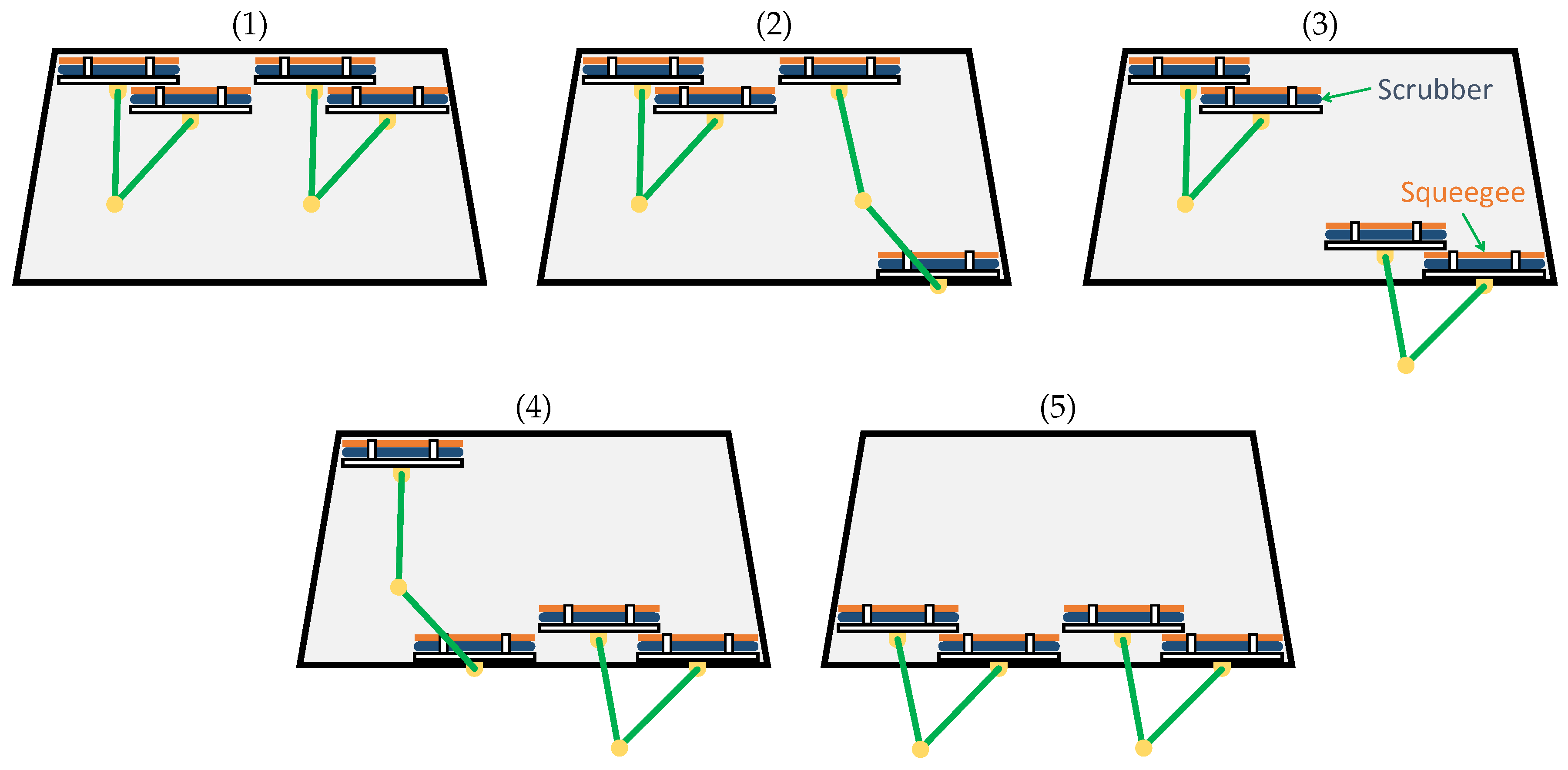
3.3. Gait Generation Based on Sequential Control

Hereafter, the sequence of the target foot position is discussed. As discussed above, in order to generate the straight basis gait, the target foot position is set as follows:
  • Lift up the idling leg vertically
  • Move the idling leg to the target step position horizontally against the glass surface
  • Bring down the idling leg to the glass surface
  • Switch the idling leg and the supporting leg, and repeat 1∼3
This paper starts from a simple algorithm to avoid complexity as a first step to realize automation control. A strategy for this is to utilize only one kinematics model to generate the trajectories. A related gait from one foot unit is generated by utilizing the single kinematics model. By setting a reference point in the center of the left foot unit, the relative position of the right foot unit with respect to each sequence is set as shown in Table 4. In Table 4, x t , y t , and z t represent the target position of the biped robot, and S x = sgn( x t ). The sequence shown in Table 4 generates trajectories that start the step from the right foot unit when moving the robot to the right and from the left foot unit when moving the robot to the left. The trajectory between each target position in Table 4 is generated via the fifth polynomial interpolation. Finally, the target angles of each actuator to track the generated trajectory are derived by inverse kinematics.

4. Experiments

This section verifies that the developed biped robot is capable of locomoting on the glass surface with the designed trajectory generator. The purpose of these experiments is to show that the locomotion abilities of the developed biped robot satisfies the requirements of accomplishing our proposing strategy. Thus, in these experiments, it was shown that the developed biped robot is able to locomote on the vertical glass wall robustly and to overcome window frame obstacles. More advanced controls including obstacle avoidance control and servo control will be designed in future work.

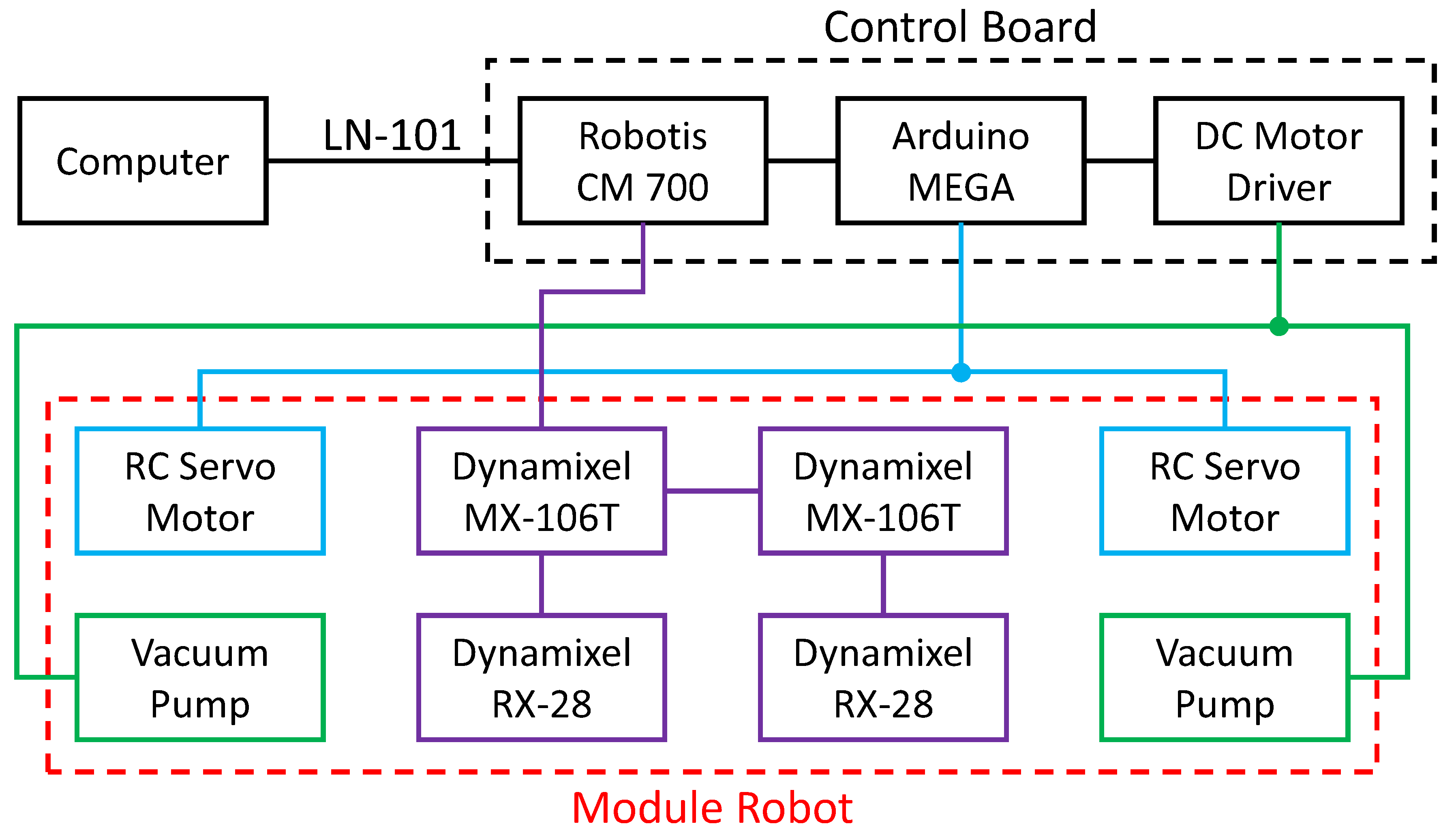
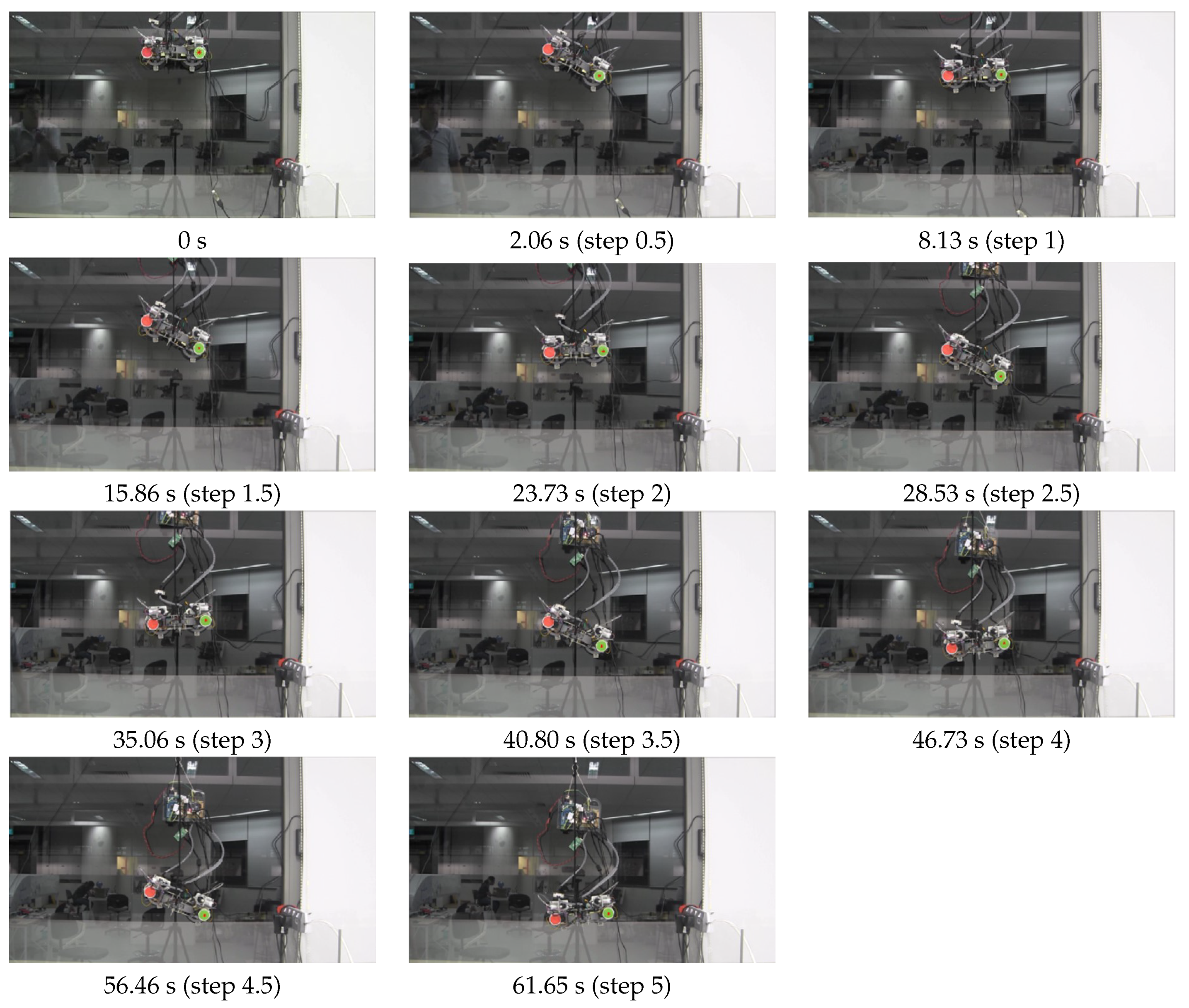
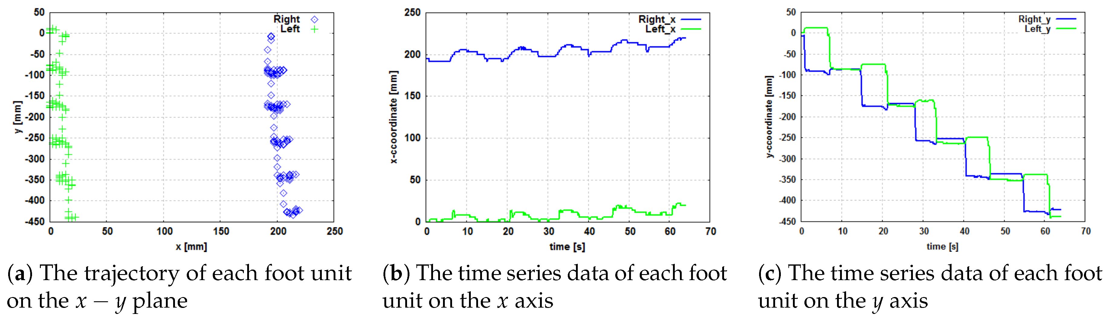
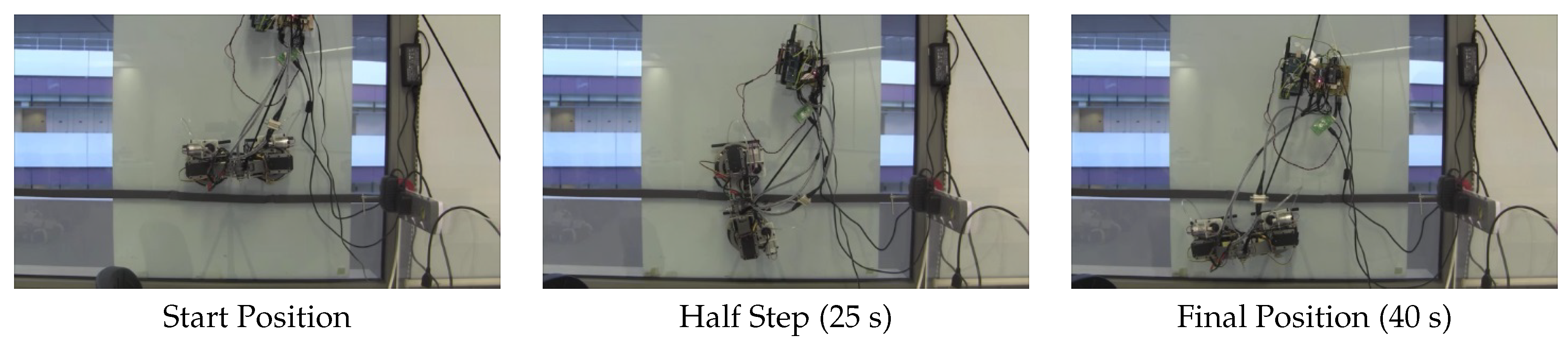
4.1. System Architecture and Experiments

Figure 13 shows a system architecture for the experiments. From Figure 13, the system mainly consists of a laptop computer for the target position indication, the biped robot, and a control board. Since the robotic system is suspended on a rope for safety purposes, the control board and power supplies such as the safety rope can be installed externally. CM-700 produced by Robotis is the main computer and performs the communication between the components and trajectory calculations. The RC servo motor and the vacuum pump for the vacuum system are controlled by Arduino MEGA 2560 via the receiving of control signals from CM-700. A power supply (6 V) for driving the RC servo motor is installed on the control board, and the 12 V supply is delivered from outside via cable. In this paper, two experiments were performed to verify the effectiveness of both its normal locomotion and its ability to overcome obstacles.
Regarding the experiment of normal locomotion, x t [cm] and y t [cm] were provided by the laptop computer. z t [cm] was set as 2.5 cm on the glass surface. The transformation time of the fifth polynomial interpolation was set T = 1.5 s.
The experiment of normal locomotion aimed to demonstrate the motion performance of the biped robot. The key points are as follows: clean the window from top to bottom, move the squeegee to track the scrubber, keep the squeegee in contact with the glass surface while cleaning a column, and clean in one direction. Snapshots and graphs of the experiment of normal locomotion with time variation are shown in Figure 14 and Figure 15.
Regarding the experiment of overcoming obstacles, x t , y t , and z t [cm] were set as x t = 15 cos ( 85 π / 180 ) , y t = 15 sin ( 85 π / 180 ) and z t = 4 . The transformation time of the fifth polynomial interpolation was set as T = 1.5 s. In addition, an obstacle supposed to represent the window frame (a 6 mm height and a 20 mm width) was attached on the glass surface. This experiment demonstrated that the biped robot is capable of overcoming a window frame obstacle. Snapshots of the experiment of overcoming obstacles with time variation are shown in Figure 16.

4.2. Discussions

Figure 14 shows that the motion performance without any human aid met the first and second key criteria: cleaning the window from top to bottom and moving the squeegee to track the scrubber. In Figure 15a indicates the trajectory of the biped robot on the x y plane, and (b) and (c) indicate the time series data of the biped robot on the x and y axis. The origin was set at the initial position of the marker equipped on the left foot unit. Figure 15 shows that the robot achieved the second key point and the fourth key point: cleaning in one direction. However, two issues were found: First, the trajectory strayed to positive in the x direction, as shown in Figure 15. This is because the controller is currently feedforward only. The experiment in this paper focused only on motion performance, rather than motion accuracy. A feedback control and state estimation system, such as SLAM, will be designed in our future work. Second, as Figure 15c shows, the support leg moved while the idling leg was moving, even though it was fixed by the vacuum suction cup, as shown in Figure 14. This is due to marker locations that are not equipped on the rotational axis of the base actuator. Since the markers are located outside the base actuator, the marker position moves according to the rotation of the base actuator. Hence, this does not represent a serious technical issue. On the basis of the above discussion, the left foot unit is always located behind the right foot unit. It is thus demonstrated that the developed biped robot is capable of locomoting on the glass surface smoothly utilizing the designed system and trajectory generator.
From Figure 16, obstacles were overcome within 40 s without any human aid. It is thus demonstrated that the developed robot can overcome window frames safely using the designed application.

5. Conclusions

This paper proposes a new class of façade cleaning robot with a biped mechanism that can overcome glass frames to maximize its area coverage. The developed robot uses active suction cups to adhere to glass walls and adopts mechanical linkage to navigate the glass surface to perform cleaning. This paper also discusses the control system of the developed robot, which consists of inverse kinematics, a fifth polynomial interpolation, and sequential control. Experiments were conducted in a real-time scenarios in order to validate the robot’s ability to cross over from one glass panel to another without any difficulties, with the objective of maximizing the coverage area. The result indicates that the developed robot achieves significantly higher performance in terms of maximum area by overcoming both negative and positive obstacles on a glass panel. Future research will focus on (1) the integration of range and inertial sensors for autonomous navigation, (2) the integration of cleaning modules in the developed system, (3) exhaustive experiments in highly diverse and complex environments to quantify the complexity of the developed platform, and (4) the development of additional features to improve power management issues.

Author Contributions

S.N. and M.R.E. conceived and designed the experiments; S.N., K.O. and P.V. performed the experiments; S.N. and P.V. analyzed the data; S.N., K.O., M.R.E. and M.I. wrote the paper.

Funding

This research is supported by the SUTD-JTC Industrial Infrastructure Innovation Center under grants IPJTCT 31501.

Conflicts of Interest

The authors declare no conflict of interest.

References

  1. Frey, C.B.; Osborne, M.A. The future of employment: How susceptible are jobs to computerisation. Technol. Forecast. Soc. Chang. 2013, 7. [Google Scholar] [CrossRef]
  2. International Fedration of Robotics. Service Robot Statistics. Available online: http://www.ifr.org/service-robots/statistics/ (accessed on 21 November 2018).
  3. Aldred, J. Burj Khalifa—A new high for high-performance concrete. In Proceedings of the Institution of Civil Engineers-Civil Engineering; Thomas Telford Ltd.: London, UK, 2010; Volume 163, pp. 66–73. [Google Scholar]
  4. Baker, W.F. The World’s tallest building. STRUCTURE, June 2011. [Google Scholar]
  5. Baker, W.F.; Korista, D.S.; Novak, L.C. Burj Dubai: engineering the world’s tallest building. Struct. Des. Tall Spec. Build. 2007, 16, 361–375. [Google Scholar] [CrossRef]
  6. Weismantle, P.A.; Smith, G.L.; Sheriff, M. Burj Dubai: an architectural technical design case study. Struct. Des. Tall Spec. Build. 2007, 16, 335–360. [Google Scholar] [CrossRef]
  7. Zeljic, A.S. Shanghai Tower Façade Design Process. In Proceedings of the International Conference of Building Envelope Systems, Vancouver, BC, Canada, 27–30 June 2010; Available online: http://www.gensler.com/uploads/documents/Shanghai_Tower_Facade_Design_Process_11_10_2011.pdf (accessed on 21 November 2018).
  8. Xia, J.; Poon, D.; Mass, D. Case study: Shanghai Tower. CTBUH J. 2010, 2010, 12–18. [Google Scholar]
  9. Zhaoa, X.; Ding, J.; Suna, H. Structural design of shanghai tower for wind loads. Procedia Eng. 2011, 14, 1759–1767. [Google Scholar] [CrossRef]
  10. BBC. Shanghai Window Cleaning Cradle Swings out of Control. Available online: http://www.bbc.com/news/world-asia-china-32176401 (accessed on 21 November 2018).
  11. BBC. Window Washers Rescued from High up World Trade Center. Available online: http://www.bbc.com/news/world-us-canada-30028969 (accessed on 21 November 2018).
  12. Zhang, H.; Zhang, J.; Zong, G.; Wang, W.; Liu, R. Sky cleaner 3: A real pneumatic climbing robot for glass-wall cleaning. IEEE Robot. Autom. Mag. 2006, 13, 32–41. [Google Scholar] [CrossRef]
  13. Zhang, H.; Zhang, J.; Zong, G. Effective nonlinear control algorithms for a series of pneumatic climbing robots. In Proceedings of the 2006 IEEE International Conference on Robotics and Biomimetics, Kunming, China, 17–20 December 2006; IEEE: Piscataway, NJ, USA, 2006; pp. 994–999. [Google Scholar]
  14. Zhang, H.; Zhang, J.; Zong, G. Requirements of glass cleaning and development of climbing robot systems. In Proceedings of the 2004 International Conference on Intelligent Mechatronics and Automation, Chengdu, China, 26–31 August 2004; IEEE: Piscataway, NJ, USA, 2004; pp. 101–106. [Google Scholar]
  15. Sun, D.; Zhu, J.; Lai, C.; Tso, S. A visual sensing application to a climbing cleaning robot on the glass surface. Mechatronics 2004, 14, 1089–1104. [Google Scholar] [CrossRef]
  16. Sun, D.; Zhu, J.; Tso, S.K. A Climbing Robot for Cleaning Glass Surface with Motion Planning and Visual Sensing; INTECH Open Access Publisher: London, UK, 2007. [Google Scholar]
  17. Serbot-AG. Available online: http://www.serbot.ch/en/ (accessed on 21 November 2018).
  18. Seo, K.; Cho, S.; Kim, T.; Kim, H.S.; Kim, J. Design and stability analysis of a novel wall-climbing robotic platform (ROPE RIDE). Mech. Mach. Theory 2013, 70, 189–208. [Google Scholar] [CrossRef]
  19. Kim, T.Y.; Kim, J.H.; Seo, K.C.; Kim, H.M.; Lee, G.U.; Kim, J.W.; Kim, H.S. Design and Control of a Cleaning Unit for a Novel Wall-Climbing Robot. Appl. Mech. Mater. 2014, 541–542, 1092–1096. [Google Scholar] [CrossRef]
  20. Kim, T.; Seo, K.; Kim, J.H.; Kim, H.S. Adaptive impedance control of a cleaning unit for a novel wall-climbing mobile robotic platform (ROPE RIDE). In Proceedings of the 2014 IEEE/ASME International Conference on Advanced Intelligent Mechatronics (AIM), Besacon, France, 8–11 July 2014; IEEE: Piscataway, NJ, USA, 2014; pp. 994–999. [Google Scholar]
  21. Fraunhofer-IFF. Available online: http://www.iff.fraunhofer.de/en.html (accessed on 21 November 2018).
  22. Böhme, T.; Schmucker, U.; Elkmann, N.; Sack, M. Service robots for facade cleaning. In Proceedings of the 24th Annual Conference of the IEEE Industrial Electronics Society, Aachen, Germany, 31 August–4 September 1998; IEEE: Piscataway, NJ, USA, 1998; Volume 2, pp. 1204–1207. [Google Scholar]
  23. Elkmann, N.; Schmucker, U.; Scharfe, H.; Schoop, C.; Kubbe, I. Drive Device for Moving a Robot or Vehicle on Flat, Inclined or Curved Surfaces, Particularly of a Glass Construction and Robot with Drive Device. U.S. Patent 5,959,424, 28 September 1999. [Google Scholar]
  24. Elkmann, N.; Hortig, J.; Fritzsche, M. Cleaning automation. In Springer Handbook of Automation; Springer: Berlin, Germany, 2009; pp. 1253–1264. [Google Scholar]
  25. Elkmann, N.; Felsch, T.; Sack, M.; Saenz, J.; Hortig, J. Innovative service robot systems for facade cleaning of difficult-to-access areas. In Proceedings of the 2002 IEEE/RSJ International Conference on Intelligent Robots and Systems, Lausanne, Switzerland, 30 September–4 October 2002; IEEE: Piscataway, NJ, USA, 2002; Volume 1, pp. 756–762. [Google Scholar]
  26. Elkmann, N.; Kunst, D.; Krueger, T.; Lucke, M.; Böhme, T.; Felsch, T.; Stürze, T. SIRIUSc–Façade cleaning robot for a high-rise building in munich, germany. In Climbing and Walking Robots; Springer: Berlin, Germnay, 2005; pp. 1033–1040. [Google Scholar]
  27. Bridge, B.; Elkmann, N.; Lucke, M.; Krüger, T.; Kunst, D.; Stürze, T.; Hortig, J. Kinematics, sensors and control of the fully automated façade-cleaning robot SIRIUSc for the Fraunhofer headquarters building, Munich. Ind. Robot Int. J. 2008, 35, 224–227. [Google Scholar]
  28. Cepolina, F.E.; Muscolo, G.G. Design of a robot for hygienization of walls in hospital environments. In Proceedings of the ISR/Robotik 2014; 41st International Symposium on Robotics, Munich, Germany, 2–3 June 2014; pp. 1–7. [Google Scholar]
  29. Akinfiev, T.; Armada, M.; Nabulsi, S. Climbing cleaning robot for vertical surfaces. Ind. Robot Int. J. 2009, 36, 352–357. [Google Scholar] [CrossRef]
  30. Ott, C.; Baumgärtner, C.; Mayr, J.; Fuchs, M.; Burger, R.; Lee, D.; Eiberger, O.; Albu-Schäffer, A.; Grebenstein, M.; Hirzinger, G. Development of a biped robot with torque controlled joints. In Proceedings of the 2010 10th IEEE-RAS International Conference on Humanoid Robots (Humanoids), Nashville, TN, USA, 6–8 December 2010; IEEE: Piscataway, NJ, USA, 2010; pp. 167–173. [Google Scholar]
  31. Al-Busaidi, A.M. Development of an educational environment for online control of a biped robot using MATLAB and Arduino. In Proceedings of the Mechatronics (MECATRONICS), 2012 9th France-Japan & 7th Europe-Asia Congress on and 2012 13th Int’l Workshop on Research and Education in Mechatronics (REM), Paris, France, 21–23 November 2012; IEEE: Piscataway, NJ, USA, 2012; pp. 337–344. [Google Scholar]
  32. Liu, C.Y.; Wang, J.C. Forecasting the development of the biped robot walking technique in Japan through S-curve model analysis. Scientometrics 2009, 82, 21–36. [Google Scholar] [CrossRef]
  33. Guan, Y.; Jiang, L.; Zhu, H.; Zhou, X.; Cai, C.; Wu, W.; Li, Z.; Zhang, H.; Zhang, X. Climbot: A modular bio-inspired biped climbing robot. In Proceedings of the 2011 IEEE/RSJ International Conference on Intelligent Robots and Systems (IROS), San Francisco, CA, USA, 25–30 September 2011; IEEE: Piscataway, NJ, USA, 2011; pp. 1473–1478. [Google Scholar]
  34. Minor, M.; Dulimarta, H.; Danghi, G.; Mukherjee, R.; Tummala, R.L.; Aslam, D. Design, implementation, and evaluation of an under-actuated miniature biped climbing robot. In Proceedings of the 2000 IEEE/RSJ International Conference on Intelligent Robots and Systems, Takamatsu, Japan, 31 October–5 November 2000; IEEE: Piscataway, NJ, USA, 2000; Volume 3, pp. 1999–2005. [Google Scholar]
  35. AbuKhalil, T.; Sobh, T.; Patil, M. Survey on decentralized modular robots and control platforms. In Innovations and Advances in Computing, Informatics, Systems Sciences, Networking and Engineering; Springer: Berlin, Germany, 2015; pp. 165–175. [Google Scholar]
  36. Patil, M.; Abukhalil, T.; Patel, S.; Sobh, T. UB robot swarm—Design, implementation, and power management. In Proceedings of the 2016 12th IEEE International Conference on Control and Automation (ICCA), Kathmandu, Nepal, 1–3 June 2016; IEEE: Piscataway, NJ, USA, 2016; pp. 577–582. [Google Scholar]
  37. Okazaki, Y.; Yamamoto, M.; Komatsu, M.; Tsusaka, Y.; Adachi, Y. Development of a Human Safe, Multi-Degree-of-Feedom Robot Arm Technology using Pneumatic Muscles (in Japanese). J. Robot. Soc. Jpn. 2010, 28, 62–70. [Google Scholar] [CrossRef]
  38. Noguchi, Y.; Iwase, M.; Hatakeyama, S.; Izutsu, M. A Yoyo Trick Realized by Parallel-Link Manipulator. In Proceedings of the 39th Annual Conference of the IEEE Industrial Electronics Society, Vienna, Austria, 10–13 November 2013; pp. 4049–4054. [Google Scholar]
  39. Takeda, Y.; Okada, M. Development of a Jumping Robot with a Non-Circular Gear. In Proceedings of the 2012 JSME Conference on Robotics and Mechatronics, Hamamatsu, Japan, 27–29 May 2012; Volume 3, pp. 2A2–V04. [Google Scholar]
Figure 1. Two key points that need to be addressed.
Applsci 08 02398 g001
Figure 2. A biped robot adapts to distinct window frames. The process of our strategy is illustrated from (1) to (5).
Applsci 08 02398 g002
Figure 3. CAD design of the robot. Each foot unit includes a cleaning unit, a suction cup, a vacuum pump, a seal mechanism, a valve to break vacuum, and servo motors for joint actuation. The robot installs a parallel linkage mechanism to keep the foot unit of the system and the glass surface parallel without any control system.
Applsci 08 02398 g003
Figure 4. A schematic figure of a vertical plane of the arm of the designed robot.
Applsci 08 02398 g004
Figure 5. The theoretical movement range of the vertical plane of the arm of the designed robot. The system is capable of moving ± 13.66 cm along the z axis and 22.54 cm along the x axis.
Applsci 08 02398 g005
Figure 6. A schematic figure of the simplified model regarding the base actuator.
Applsci 08 02398 g006
Figure 7. Designable range satisfying Equation (3). “×” highlighted in red represents the actual design parameter, and it satisfies Equation (3). Thus, MX-106T is able to generate enough driving torque as a base actuator.
Applsci 08 02398 g007
Figure 8. A schematic figure of the simplified model regarding the arm actuator.
Applsci 08 02398 g008
Figure 9. Designable range satisfying Equation (4). “×” highlighted in red represents the actual design parameter, and it satisfies Equation (4). Thus, RX-28 is able to generate enough driving torque as a base actuator.
Applsci 08 02398 g009
Figure 10. A diagram of the vacuum system. Top: The switching valve is controlled by the RC servo motor via a cam mechanism. Bottom: Chamber air in the suction cup is sucked once the toggle is pushed in.
Applsci 08 02398 g010
Figure 11. Photograph of the actual robot.
Applsci 08 02398 g011
Figure 12. The schematic figure of the biped robot in three-dimensional space.
Applsci 08 02398 g012
Figure 13. A system architecture for the experiments. The system mainly consists of a laptop computer for the target position indication, the biped robot, and a control board. Since the biped robot is suspended on a rope for safety purposes, the control board and power supplies such as the safety rope can be installed externally.
Applsci 08 02398 g013
Figure 14. The snapshots of the normal-locomotion experiment with time variation. Five normal locomotions within 61.65 s were realized without any human aid.
Applsci 08 02398 g014
Figure 15. The graph of the normal locomotion experiment. (ac) are the graphs of numerical data related to the normal locomotion between five steps. The origin was set on the initial left foot unit marker.
Applsci 08 02398 g015
Figure 16. Snapshots of the overcoming obstacles experiment with time variation. Obstacles were overcome within 40 s without any human aid.
Applsci 08 02398 g016
Table 1. Specifications of the servo motors.
Model NumberMX-106TRX-28HS-5085MG
MakerROBOTISROBOTISHITEC
Stall Torque8.4 Nm3.7 Nm4.3 kg·cm
No Load Speed45 rpm85 rpm0.13 rec/60deg
Weight153 g72 g21.9 g
Voltage12 V12 V6 V
Table 2. Specification of the vacuum pump.
Model NumberDP0125
MakerNitto Kohki
Attainable Vacuum−33.3 kPa
Free Air Displacement2.5 L/min
Voltage12 V
Weight80 g
Table 3. Physical Parameters. ( i = 1 , 2 ).
NotationParameters
l i Link length
m i Mass
dLength from center of the foot unit to the joint
l 3 Length between the joint of each foot unit
x d Length of l 3 on the X–Y plane
Table 4. Target positions in each sequence.
Sequencex [cm]y [cm]z [cm]
1 x 0 y 0 S x z t
2 S x x t S x y t S x z t
3 S x x t S x y t z 0
4 S x x t S x y t S x z t
5 x 0 y 0 S x z t
6 x 0 y 0 z 0

