Featured Application
The application scenario of this paper is to develop a supercavitating torpedo to assure stability while approaching a target in disturbed environments.
Abstract
Supercavitation is a hydrodynamic phenomenon in which an underwater body is almost entirely inside the cavity wall. Since the density of the gas is much lower than that of water, skin friction drag can be reduced considerably. We develop controllers to control a supercavitating vehicle, which is a high-speed vehicle with a cavitator at its nose. We designed controllers based on impulsive inputs, which are used to change the pitch of the vehicle slightly. This slight pitch change is desirable, since a large pitch change can lead to instability of the vehicle due to large planing force. Moreover, our impulsive controllers are robust to disturbances. In practice, the vehicle consumed its fuel to move forward. This fuel consumption led to changing parameters of the vehicle, such as mass. To handle this changing system, we used fuzzy impulsive controllers. We ran simulations to verify the effectiveness of our controllers.
1. Introduction
Supercavitation is a hydrodynamic phenomenon in which an underwater body is almost entirely inside the cavity wall (a layer of gas bubbles). Since the density of the gas is much lower than that of water, skin friction drag can be reduced considerably. A supercavitating vehicle is a high-speed vehicle with a cavitator at the nose of the vehicle. Due to the cavitator, a cavity wall is generated containing the body. In this way, skin friction drag becomes almost zero.
There are many papers on modelling the system dynamic of supercavitating vehicles, e.g., [1,2,3,4,5,6]. The authors of Reference [5] presented a dynamic model that captures the physics of a supercavitating vehicle with a disk cavitator. Based on the dynamic model, Reference [5] presented how to find the trim input so that the vehicle moves straight with a constant velocity. The authors of Reference [3] provided integrated modelling of a supercavitating vehicle from partially cavitating condition at low speed to supercavitation condition at high speed including transition phase. The authors of Reference [4] presented modelling and dynamics for a supercavitating vehicle with no fins. Reference [5] discussed how to optimally design a supercavitating vehicle with a disk cavitator, considering maximum range, maximum turn rate, and high maneuverability. The authors of Reference [6] considered a supercavitating vehicle with a conical cavitator and presented an Linear Quadratic Regulator (LQR) controller for pitch and roll rate control.
Many papers have tackled how to control a supercavitating vehicle while maintaining stability. The authors of References [7,8] considered how to control a supercavitating vehicle as the vehicle moves between a planing and a non-planing condition. References [7,8] used switching control laws to handle this switching condition. The authors of Reference [9] developed an adaptive control law for a supercavitating vehicle while the vehicle is in the transition phase (partial cavity condition). The authors of Reference [10] presented a control law based on H-infinity optimization so that the pitch angle tracks the reference pitch command while avoiding planing.
Our system model is developed based on that in Reference [5]. This paper uses Logvinovich’s model presented in References [5,11,12,13,14,15,16,17,18], since this model is known to be accurate considering unsteady cavity. The authors of Reference [5] considered a constant cavitation number. In reality, the cavitation number changes associated to the speed of the vehicle and to the depth of the vehicle. Accordingly, this paper considers the case where the cavitation number changes depending on changing systems.
Considering the case where the full cavity is developed, we present control laws to control depth and roll of the vehicle. We designed the control laws based on impulsive inputs. Impulsive inputs are used to change the pitch of the vehicle slightly. This small change is desirable, since a large pitch change can lead to instability due to large planing force. By minimizing the pitch change, we can avoid planing completely.
The planing force is large and occurs at dominating frequencies of about 10~50 Hz. Due to this high frequency, very fast and expensive actuators are required to actively stabilize and control the vehicle under planing [19]. Since our control laws avoid planing completely, we can reduce the drag associated to planing force and do not require expensive actuators.
Sliding mode controls (SMCs) are well-known for their robustness to uncertain models [20]. This robustness comes from the fact that the SMCs switch between two distinct modes to converge to desired states. Our impulsive control laws are similar to the SMCs in that we switch between two distinct modes to converge to desired states.
Consider the case where the vehicle follows a target depth under our impulsive control laws. Since the input of the vehicle switches between two modes, the vehicle depth does not converge to the target depth exactly. Instead, the vehicle fluctuates up and down the target depth. However, it is desirable that we reduce the fluctuation as the vehicle follows the target depth. Inspired by fuzzy control methods in References [21,22,23], this paper introduces an adaptive fuzzy method to reduce the fluctuation of the vehicle, as it follows the target depth.
In practice, the vehicle consumes its fuel to move forward. This fuel consumption leads to changing parameters of the vehicle. For instance, center of gravity, mass, and mass moments of inertia matrix change as the traveling distance increases. To cope with this changing system, we use fuzzy impulsive control laws. As far as we know, this paper is novel in developing control laws for a supercavitating vehicle, which can handle changing systems.
Our contributions are summarized as follows: we first develop realistic simulation models, considering varying cavitation numbers, vehicle depth, environmental disturbance, and fuel consumption. Next, we develop the control laws for a supercavitating vehicle and verify the robustness of the control laws based on our realistic simulation models.
For comparison, we compare the proposed control laws with a control law presented in [17,18]. The control law in [17,18] has been shown to exhibit both stable and limit-cycle planing motion. However, under our realistic simulation models, the control law in References [17,18] diverges due to planing.
2. Preliminary Information
2.1. System Models
We introduce our system model briefly. This paper considers the modelling of the system dynamic under fully developed cavitating conditions, as presented in Reference [5], which used a full six-Degree-Of-Freedom (DOF) nonlinear model that captures the physics of the system.
Table 1 shows the state variables, which are commonly used in six-DOF systems. This paper uses 12 state variables as presented in Table 1.

Table 1.
State Variables.
We controlled four fins (fins 1, 2, 3, and 4) as well as the pitch of the cavitator. Therefore, our control variables were as follows.
In (1), denotes the deflection angle of the i-th fin. Also, denotes the deflection angle of the cavitator pitch.
This paper considers the case where the origin of the body-fixed coordinate system is located at the center of gravity. This paper also considers the case where four fins are oriented in the cross formation and line up with the principal axis. The arrangement of four fins is shown in Figure 1. This view is from the nose of the vehicle. In this figure, numbers 1, 2, 3, and 4 represent fin numbers.
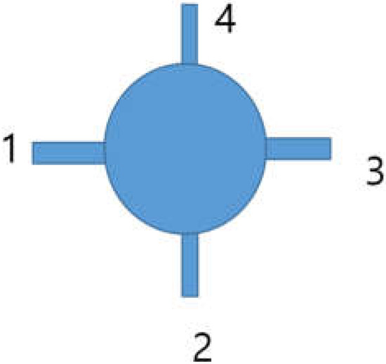
Figure 1.
Fin arrangement. In this figure, numbers 1, 2, 3, and 4 represent fin numbers.
Under these settings, mass moments of inertia () matrix is a diagonal matrix. Then, the six-DOF system dynamics are computed as follows.
In (2) and (3), is the mass of the vehicle. is the force generated by , and is the moment generated by . are diagonal elements in . See Reference [5] for the detailed explanation for six-DOF system dynamics of the vehicle. Moreover, Reference [5] presented how to derive each force (cavitator force , thruster force , plane force , gravity force , and fin force ) and its associated moment in (2) and (3). We omit the presentation of each force and moment due to page limit of the paper. See Reference [5] for detailed explanation of each force and its associated moment in (2) and (3).
Using the six-DOF system dynamics in (2) and (3), and open loop system of the vehicle can be derived as presented in Reference [5]. Based on the open loop system, Reference [5] presented how to find the trim input so that the vehicle moves straight with a constant velocity. Note that there is no rotation about the center of gravity (CG) for a trimmed vehicle. Let denote the trim input of the vehicle, which is given as follows.
See that the second and the fourth elements in the trim input from Equation (4) are zero. This implies that in the trim input, fins 2 and 4 are not deflected at all. Note that (4) is derived using system dynamics (2) and (3).
In the configuration of the vehicle, fins are positioned close to the CG of the vehicle. Hence, moment generated by fin deflection is small. We used this fin configuration, since we want to make the pitch rate of the vehicle as small as possible. In the case where we locate fins far from the CG of the vehicle, moment generated by fin deflection is large. This case, the pitch rate increases, which may lead to planing (collision between the body and the cavity wall).
3. Tracking Control Laws
3.1. Assumptions and Definitions
This paper considers the case where the vehicle is not equipped with planning rejection controllers. The planing force is large and occurs at dominating frequencies of about 10~50 Hz. Due to this high frequency, very fast and expensive actuators are required to actively stabilize and control the vehicle under planing. Since our control laws avoid planing completely, we can reduce the drag associated to planing force and do not require expensive actuators.
Due to fuel consumption, center of gravity, mass, and mass moments of inertia matrix change as time goes on. Let vehicle parameters denote these changing values for convenience. Let denote the vehicle parameters at time step . Let denote the time step when the fuel tank becomes empty.
We assume that the vehicle can check its fuel consumption in real time. We further assume that the vehicle can access a table showing the relationship between fuel consumption and the vehicle parameters. Using this table, the vehicle can check its changing parameters.
We further assume that our vehicle is equipped with Inertial Measurement Units as well as depth sensors. Thus, the vehicle can measure its depth and attitude (roll, pitch, and yaw) in real time. Using these measurements, the vehicle generates its control inputs.
As we control the depth of the vehicle, we do not control the lateral motion of the vehicle. The cavitator, fins 1 and 3 are called elevators, providing some component of steady lift to support the body. We control the cavitator, fins 1 and 3 to change the depth of the vehicle. Fins 1 and 3 are located on both sides of the vehicle. See Figure 1.
Fins 2 and 4 are called rudders that stabilize the vehicle in roll. In ideal environments without disturbances, the roll of the vehicle does not change as time goes on. Thus, we do not have to control the rudders (fins 2 and 4). However, due to disturbances in real environments, the roll of the vehicle changes as time goes on. This situation occurred as we add zero-mean Gaussian noise to control inputs of the vehicle to simulate disturbance in inputs. To stabilize the roll to zero in noisy environments, we control rudders, as presented in Section 3.6.
Let target depth denote the desired depth of the vehicle. We say that the pitch is aligned in the following two cases:
- The target depth is deeper than the depth of the vehicle and the pitch of the vehicle is negative.
- The target depth is shallower than the depth of the vehicle and the pitch of the vehicle is positive.
Once the pitch is aligned, then the vehicle will reach the target depth as long as the vehicle moves straight while not rotating about the CG.
Note that the control inputs, the deflection angles of fins or cavitator, cannot change abruptly due to the actuator limit. Considering this constraint, let input command denote the desired input of the vehicle. Once an input command is set, then the control input changes to reduce the difference between the command and the current input.
For instance, let denote an input command for the cavitator pitch angle. Also, let denote the cavitator angle at time step . Let denote the maximum angular rate of the cavitator pitch. In the case where , we set as In the case where , we set as Here, is the sampling interval. Also, denotes the smaller value between and .
Let elevator command denote an input angle command associated to the cavitator, fins 1 and 3. Also, let rudder command denote an input angle command associated to fins 2 and 4.
3.2. Derivation of Control Laws
We present two theorems that are used to derive our control laws.
Theorem 1.
Using the trim input in the full cavity state, the rotation of the vehicle about the CG is zero.
Proof.
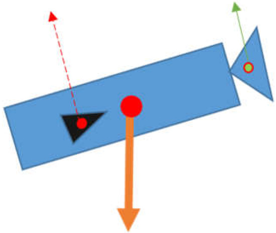
As the vehicle is in the full cavity state, all forces applied to the vehicle are the fin force , the cavitator force , the thruster force , and the gravity of the vehicle . See (2) and (3). The skin friction drag, the plan force, and the buoyancy force are not generated, since the body of the vehicle does not intersect water.
In the trim condition, (the moment generated by the gravity) is zero, since the gravity force applies to the CG. Moreover, (the moment generated by the thruster) is zero, since the thruster force applies along the body axis.
(the moment generated by the fin) is nullified by (the moment generated by the cavitator). Otherwise, the vehicle cannot move straight while not rotating about the CG.
See Figure 2 for an illustration of the case where we apply while the pitch is not zero. In Figure 2, the lifting force (the normal component of such that the component is normal to the body axis) generated by the fins is depicted as a red dotted arrow. Also, the lifting force (the normal component of such that the component is normal to the body axis) generated by the cavitator is depicted as a green arrow. These two lifting forces do not generate a moment, since is nullified by . which is applied to the CG is depicted as a bold arrow in Figure 2.

Figure 2.
We apply while the pitch is not zero.
Therefore, using the trim input in the full cavity state, the rotation of the vehicle about the CG is zero. □
Consider the case where the vehicle moves with a constant velocity by applying as depicted in Figure 2. By changing the cavitator input in , we can change the lifting force (the normal component of such that the component is normal to the body axis) generated by the cavitator. Let us assume that we change the cavitator input in slightly so that we reduce the lifting force generated by the cavitator. See Figure 3 for an illustration. Compared to Figure 2, the lifting force generated by the cavitator decreased. In this case, a moment is generated and the body rotates in the clockwise direction as depicted in Figure 3. (the moment generated by the gravity) is zero, since the gravity force applies to the CG. Our depth control laws are designed using the moment generated by changing the cavitator input slightly.
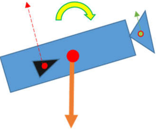
Figure 3.
We change slightly to generate a moment, and the body rotates in the clockwise direction.
Theorem 2 presents the relationship between the deflection of rudder and the roll of the vehicle. Beforehand, we need to introduce several definitions. Consider the case where the vehicle moves with a constant velocity in the full cavity state. The fin force generated by deflecting fin 2 by a certain angle can be decomposed into three forces in the body-fixed frame. Here, the upper subscript 2 indicates fin 2. Similarly, the fin force generated by deflecting fin 4 by can be decomposed into three forces in the body-fixed frame.
See Figure 4 for an illustration. This figure shows the vehicle seen from the nose of the vehicle. In Figure 4, the dotted circle indicates the cavity intersecting the rudders. The pivot points of fins 2 and 4 are depicted with two crosses. Let denote the distance between the pivot point of i-th fin and the principal axis of the vehicle. Under the configuration of our vehicle, for all
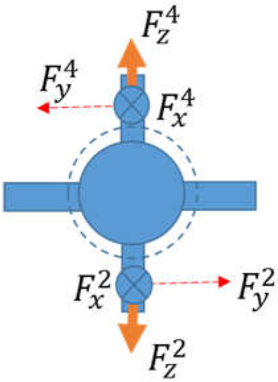
Figure 4.
The dotted circle indicates the cavity intersecting the rudders. .
Theorem 2.
Consider the case where the vehicle moves with a constant velocity in the full cavity state. As we deflect two rudders by the identical angle, then the vehicle rolls with angular acceleration of. Here, m is the mass of the vehicle.
Proof.
Consider the case where the vehicle moves straight in the full cavity state. As the vehicle is in the full cavity state, the vehicle speed is sufficiently fast (85 m/s), as presented in Section 4. Thus, buoyancy effect on the cavity can be ignored in this analysis. Since the vehicle moves straight, the principal axis of the vehicle coincides with the cavity center line using the Logvinovich independence principle, see Figure 4. Thus, the immersion depth of fin 2 is identical to that of fin 4. Since two fins are deflected by the identical angle, we have
The moment generated by is nullified by that generated by . In other words, , since Similarly, the moment generated by is nullified by that generated by , since The moment generated by is This moment is identical to (the moment generated by ), since (the sum of two moments) makes the vehicle roll in one direction. Hence, the net force to roll the vehicle is Since the vehicle’s mass is m, the vehicle rolls with angular acceleration of . □
3.3. Depth Control Not Considering Fuel Consumption
First, consider the case where the current depth of the vehicle is deeper than the target depth. In this case, the pitch is aligned in the case where it is a positive value. We control the elevators to change the depth of the vehicle.
We set the elevator command to
In this equation, is a constant. In (5), ~ implies that the associated inputs (inputs associated to rudders) are used to make the roll of the vehicle converge to zero. Section 3.6 presents how to set the rudder command. Compared to in (4), we slightly change the cavitator pitch angle to give the vehicle a torque to change its pitch.
After maintaining the elevator command as for s, we check whether the pitch is aligned. is the minimum dwell time for . This implies that is set as our elevator command for seconds, whether the pitch is aligned or not. As long as the pitch is not aligned, we maintain the elevator command as . Once the pitch is aligned, we set the elevator command to the following .
At the instant when we switch to , the pitch is aligned. We further show that at the instant when we switch to , the pitch is almost zero. The duration of is bigger than or equal to seconds. Consider the case where the duration of is seconds. Since , the pitch is almost zero at the instant when we switch back to . Next, consider the case where the duration of is bigger than seconds. The elevator command changes to at the instant when the sign of the pitch changes. Hence, the pitch is almost zero at this instant.
Using Theorem 1, the rotation of the vehicle about the CG is zero under the trim input in the full cavity state. Since the pitch is aligned, the vehicle will reach the target depth in finite time.
There may be a case where maintaining the elevator command as does not lead to aligned pitch in finite time. In this case, we need to give more torque to the vehicle. Thus, if the duration of applying is longer than a certain threshold, say , then we use instead of in (5). Here, . In this way, we update .
Next, consider the case where the current depth of the vehicle is shallower than the target depth. The pitch is aligned in the case where it is a negative value. We set the elevator command to
See that we slightly change the cavitator pitch angle to give the vehicle a torque to change its pitch. is set as our elevator command for seconds, whether the pitch is aligned or not. After maintaining the elevator command as for seconds, we check whether the pitch is aligned. As long as the pitch is not aligned, we maintain the elevator command as . Once the pitch is aligned, we set the elevator command back to .
At the instant when we switch to , the pitch is aligned. We further show that at the instant when we switch back to , the pitch is almost zero. The duration of is bigger than or equal to seconds. Consider the case where the duration of is seconds. Since , the pitch is almost zero at the instant when we switch back to . Next, consider the case where the duration of is bigger than seconds. The elevator command changes to at the instant when the sign of the pitch changes. Hence, the pitch is almost zero at this instant.
Using Theorem 1, the rotation of the vehicle about the CG is zero under the trim input in the full cavity state. Since the pitch is aligned, the vehicle will reach the target depth in finite time.
There may be a case where maintaining the elevator command as does not lead to aligned pitch in finite time. In this case, we need to increase the moment so that the pitch rate of the vehicle increases. Thus, in the case where the duration of applying is longer than a certain threshold, say then we use instead of in (7). Here, . In this way, we update .
3.4. Depth Control Considering Fuel Consumption
In this subsection, we introduce depth control laws considering fuel consumption. For each , we find the associated trim input using the approach in Section 2.1. Note that as we search for the trim input associated to each , we use the vehicle’s dynamics (2) and (3).
However, in the case where is too large, it may be time-consuming to derive the trim input for each . To resolve this, we can use linear interpolation. For instance, consider the case where we have and , where . Using and , we derive and respectively. For any between and , we estimate as
As the parameters change from to , we update the trim input from to . In other words, we update in (4) as follows: . Then, we use the updated to derive (5)–(7).
3.5. Adjusting Δ as the Vehicle Follows the Target Depth
Consider the case where the vehicle follows a target depth under our control laws. Since the input of the vehicle switches among (5)–(7), the vehicle depth does not converge to the target depth exactly. Instead, the vehicle fluctuates up and down the target depth. However, it is desirable that we reduce the fluctuation as the vehicle follows the target depth.
We introduce a fuzzy method to reduce the fluctuation of the vehicle, as it follows the target depth. At each time step , we store the error between the vehicle’s depth and the target depth: . Then, we check the variance of the error, which is given as follows.
where w > 0 is a window size to derive the variance. In the case where is less than a certain threshold, say then we assume that the vehicle is following a target depth. In this case, we set in both (5) and (7) to . In this way, we can reduce the torque to rotate the vehicle. Since the torque is reduced, we can reduce the fluctuation as the vehicle follows the target depth.
3.6. Rudder Control to Stabilize the Roll
To make the roll of the vehicle converge to zero in disturbed environments, the rudder command is set as where is the roll of the vehicle and is a constant. is the sign of . Under our depth control laws, the vehicle moves straight using (6) or changes its pitch using (5) or (7).
Consider the case where the vehicle moves straight using (6). In the case where we deflect two rudders by the identical angle, the vehicle rotates in one direction using Theorem 2. Thus, by setting the rudder command as , the roll of the vehicle converges to zero.
Next, consider the case where the vehicle changes its pitch using (5) or (7). Recall that under our depth control laws, the pitch rate of the vehicle is small to satisfy that . This implies that the vehicle moves almost straight. Thus, by setting the rudder command as , the roll of the vehicle converges to zero.
Sliding mode controls (SMCs) are well-known for their robustness to uncertain models [20]. This robustness comes from the fact that the SMC switches between two distinct modes to converge to desired states. is similar to the SMC in that it switches between two distinct modes to converge to desired states. The robustness of our control laws is verified using MATLAB simulations.
4. Simulation Results
We present the MATLAB simulation results for our controllers. Note that we consider the case where the vehicle is in the full cavity state. To simulate the vehicle in the full cavity state, we set the initial speed of the vehicle as 85 m/s. Note that as the vehicle speed is 85 m/s, the vehicle is in the full cavity state. The speed of the vehicle at trim condition is also set to 85 m/s.
We set simulation parameters as follows: , the maximum angular rate of the cavitator, is 400/3 degrees per second. s, degrees, degrees, , s, , and = 0.5 degrees.
We simulate scenarios where the target depth is shallow, i.e., the vehicle moves close to the sea surface. This is to avoid the case where the system diverges due to decreased cavity size. In the simulations, we set the cavitation number considering the depth of the vehicle. Since , increases as the depth of the vehicle increases. As increases, increases. . Thus, reduces as increases, which implies that the cavity size reduces. In this case, planing occurs and the system diverges. This is unavoidable considering natural cavity (We acknowledge that our simulation neglects the change of the cavity shape related to the fact that the vehicle is close to water surface. In practice, we considered using gas ventilation to maintain the cavity size [24]. We argue that it is desirable to make the vehicle move close to the water surface, since the cavitation number increases as the depth of the vehicle increases. This implies that as the depth of the vehicle increases, we need to increase ventilating rate to maintain the cavity size).
In the simulations, we consider the case where the CG exists 2.249 m from the nose of the vehicle initially. However, the CG moves toward the nose of the vehicle with a constant speed so that the CG exists 2 m from the nose of the vehicle after the vehicle runs for 50 s. We assume that this CG movement occurs due to fuel consumption.
4.1. Proportional-Derivative (PD) Depth Controller (Noiseless Environments)
For comparison, we tested a control law presented in References [17,18]. This control law has been shown to exhibit both stable and limit-cycle planing motion [17,18]. The control law uses the pitch angle of the cavitator as its control variable. Also, this subsection considers noiseless environments. In other words, we do not add noise to control inputs in this subsection. Initial depth of the vehicle is 0 m in this scenario, since References [17,18] also considered the case where the initial depth of the vehicle is zero.
The control law is as follows: . This control law was designed to make the vehicle move straight while maintaining the zero depth. As we used as our input command, the system diverged due to large planing force in our simulations. Figure 5 shows the planing force with respect to time. The system diverges even before 0.14 s have passed.
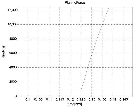
Figure 5.
The planing force with respect to time (Proportional-Derivative (PD) depth controller).
4.2. Control Not Considering Fuel Consumption (Noiseless Environments)
We present the MATLAB simulation results for our depth controllers based on Equations (5)–(7). This subsection considers noiseless environments. In other words, we do not add noise to control inputs in this subsection. The initial depth of the vehicle is 0.5 m. The target depth is 0.3 m. The depth control laws presented in this subsection do not consider fuel consumption. Hence, we do not update as time goes on. We use at time step 0 as our constant trim input and use it to derive (5)–(7).
We planned to run the simulation for 50 s. However, the system diverges due to large planing force after the vehicle runs for 13.7 s.
Figure 6 shows the depth of the vehicle with respect to time. Recall that the CG exists 2 m from the nose of the vehicle after the vehicle runs for 50 s. Since the CG moves, trim input must be adjusted according to the varying CG. However, we used at time step 0 as our constant trim input and used it to derive (5)–(7). Initially, the depth of the vehicle reaches the target depth (0.3 m) after the vehicle runs for almost 3 s. However, the vehicle gradually leaves the target depth as time goes on. This occurs due to the fact that in the control laws presented in this subsection, we do not adjust the trim input considering the fuel consumption. The planing force appears from 13.3 s to 13.76 s. Initially, the planing force is not large. However, as time goes on, the planing force increases. We conjecture that the system diverges due to the large planing force.
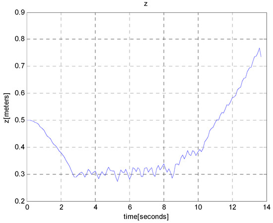
Figure 6.
The depth of the vehicle with respect to time (controllers not considering fuel consumption).
4.3. Control in Noisy Environments, Considering Fuel Consumption
We present the MATLAB simulation results for our control laws in noisy environments. We further consider fuel consumption of the vehicle as time goes on.
To simulate noisy environments, we added zero-mean Gaussian noise with standard deviation 0.1 degrees to deflection angles of the vehicle. Recall that degrees and that degrees. Thus, noise is significant compared to control inputs. We use the rudder control in Section 3.6 to control roll motions in noisy environments.
In this subsection, we simulate the case where the target depth varies as time goes on. This is a practical scenario, since the vehicle may have to change its depth while performing a mission. We run the simulation for 50 s. During the first 12.5 s, the target depth is set to 0.3 m. During the second 12.5 s, the target depth is set to 0.5 m. During the third 12.5 s, the target depth is set to 0.3 m. During the fourth 12.5 s, the target depth is set to 0.5 m.
In this subsection, we consider fuel consumption. Hence, we update the trim input as follows: . Then, we use the updated to derive (5)–(7). Also, we use the roll control law presented in Section 3.6 to maintain zero roll in noisy environments.
Figure 7 shows the depth of the vehicle with respect to time. See that the depth of the vehicle changes according to target depth change. We use the fuzzy method in Section 3.5 to reduce the fluctuation of the vehicle, as it follows the target depth. Thus, the fluctuation of the vehicle gradually decreases as time goes on.
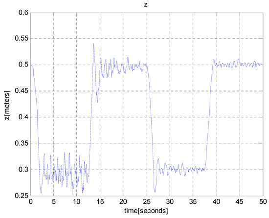
Figure 7.
The depth of the vehicle with respect to time (controllers considering noisy environments and fuel consumption).
Figure 8 shows the change of with respect to time. See that the pitch angle is almost zero, oscillating between −1 degree and 1 degree. This small pitch is desirable, since a large pitch change leads to large planing force. See that the roll angle is almost zero, which is achieved by our roll control.
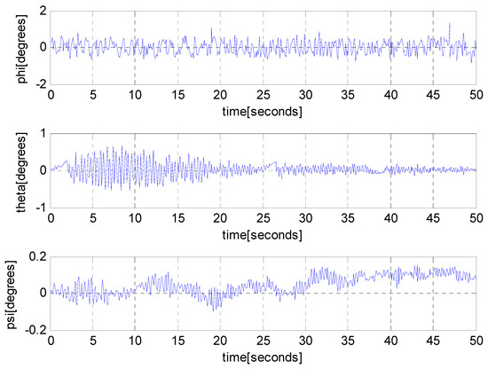
Figure 8.
The change of with respect to time (controllers considering noisy environments and fuel consumption).
Figure 9 shows the change of deflection angles with respect to time. Since changes as time goes on, we can see that the deflection angles gradually change as time goes on. This change can be seen clearly in the last subplot of Figure 9. Also, Figure 9 shows that deflection angles are disturbed considerably.
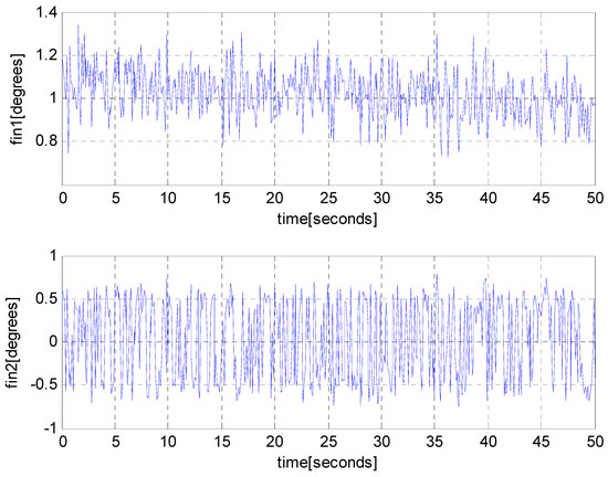
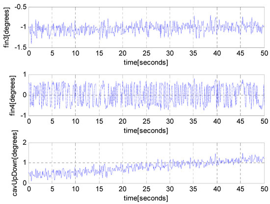
Figure 9.
The deflection angles with respect to time (controllers considering noisy environments and fuel consumption).
Figure 10 shows the distance between the transom of the vehicle and the cavity wall. In the case where this distance is less than zero, planing occurs. The planing force does not appear in the simulation, since the distance does not decrease below zero.
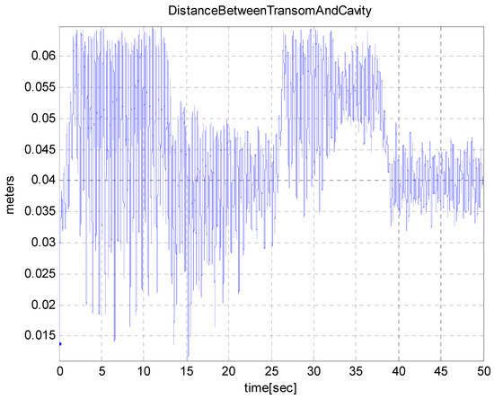
Figure 10.
The distance between the transom of the vehicle and the cavity wall (controllers considering noisy environments and fuel consumption).
5. Conclusions
This paper developed robust control laws to control depth and roll of a supercavitating vehicle. We designed controllers based on impulsive inputs. In practice, the vehicle consumed its fuel to move forward. This fuel consumption led to changing parameters of the vehicle. To cope with this changing system, we used fuzzy impulsive control laws. As far as we know, this paper is novel in developing control laws for a supercavitating vehicle, which can handle changing systems. We further developed realistic simulation models, considering varying cavitation number, vehicle depth, environmental disturbance, and fuel consumption. Then, we verify the robustness of our control laws based on the realistic simulation models. This paper considers a supercavitating vehicle which can change its depth while not changing its course. As for our future works, we will pursue developing a supercavitating torpedo to assure stability while tracking a target through active course and depth controls.
Conflicts of Interest
The author declares no conflict of interest.
References
- Vanek, B.; Bokor, J.; Balas, G.J.; Arndt, R.E.A. Longitudinal Motion Control of a High-Speed Supercavitation Vehicle. J. Vib. Control 2007, 13, 159–184. [Google Scholar] [CrossRef]
- Euteneuer, E.A. Further Studies into the Dynamics of a Supercavitating Torpedo. Master’s Thesis, University of Minnesota, Minneapolis, MN, USA, 2003. [Google Scholar]
- Kim, S.; Kim, N. Integrated dynamics modelling for supercavitating vehicle systems. Int. J. Nav. Archit. Ocean Eng. 2015, 7, 346–363. [Google Scholar] [CrossRef]
- Mokhtarzadeh, H. Supercavitating Vehicle Modeling and Dynamics for Control. Master’s Thesis, University of Minnesota, Minneapolis, MN, USA, 2010. [Google Scholar]
- Ahn, S. An Integrated Approach to the Design of Supercavitating Underwater Vehicles. Ph.D. Thesis, Georgia Institute of Technology, Atlanta, GA, USA, 2007. [Google Scholar]
- Goel, A. Robust Control of Supercavitating Vehicles in the Presence of Dynamic and Uncertain Cavity. Ph.D. Thesis, University of Florida, Gainesville, FL, USA, 2005. [Google Scholar]
- Kirschner, I.N.; Kring, D.C.; Stokes, A.W.; Fine, N.E.; Uhlman, J.S. Control Strategies for Supercavitating Vehicles. J. Vib. Control 2002, 8, 219–242. [Google Scholar] [CrossRef]
- Cao, Z. Model-Based Feedback Control of High-speed Supercavitating Vehicles. Mod. Appl. Sci. 2009, 3, 34–41. [Google Scholar] [CrossRef]
- Kim, S.; Kim, N. Neural network-based adaptive control for a supercavitating vehicle in transition phase. J. Mar. Sci. Technol. 2015, 20, 454–466. [Google Scholar] [CrossRef]
- Sanabria, D.E.; Balas, G.J.; Arndt, R.E.A. Planing Avoidance Control for Supercavitating Vehicles. In Proceedings of the American Control Conference, Portland, OR, USA, 4–6 June 2014; pp. 4979–4984. [Google Scholar]
- Reichardt, H. The Laws of Cavitation Bubbles at Axially Symmetric Bodies in a Flow; Ministry of Aircraft Production Volkenrode (MAP-VG), Reports and Translations 766; Office of Naval Research: Arlington, VA, USA, 1946. [Google Scholar]
- Logvinovich, G.V. Hydrodynamics of Free-Boundary Flow; Tech. rep.; translated from the Russian (NASA-TT-F-658); U.S. Department of Commerce: Washington, DC, USA, 1972.
- Nesteruk, I. Supercavitation: Advances and Perspectives A Collection Dedicated to the 70th Jubilee of Yu. N. Savchenko; Springer: Berlin/Heidelberg, Germany, 2012. [Google Scholar]
- Nguyen, V. Dynamics and Control of Non-Smooth Systems with Applications to Supercavitating Vehicles. Ph.D. Thesis, University of Maryland, College Park, MD, USA, 2011. [Google Scholar]
- Sanabria, D.E. Modeling, Robust Control, and Experimental Validation of a Supercavitating Vehicle. Ph.D. Thesis, University of Minnesota, Minneapolis, MN, USA, 2015. [Google Scholar]
- Savchenko, Y.N.; Semenenko, V.N.; Putilin, S.I. Unsteady Supercavitated motion of Bodies. Int. J. Fluid Mech. Res. 2000, 27, 109–137. [Google Scholar] [CrossRef]
- Dzielski, J.; Kurdila, A. A Benchmark Control Problem for Supercavitating Vehicles and an Initial Investigation of Solutions. J. Vib. Control 2003, 9, 791–804. [Google Scholar] [CrossRef]
- Nhuyen, V.; Balachandran, B. Supercavitating vehicle maneuvering with delay and non-steady planning. Appl. Hydromech. 2013, 15, 62–74. [Google Scholar]
- Sanabria, D.E.; Arndt, R.E.A. Robust control of a small-scale supercavitating vehicle: From modeling to testing. Ocean Eng. 2018, 160, 412–424. [Google Scholar] [CrossRef]
- Healey, A.J.; Lienard, D. Multivariable Sliding mode control for autonomous diving and steering of unmanned underwater vehicles. IEEE J. Ocean Eng. 1993, 18, 327–339. [Google Scholar] [CrossRef]
- El Hajjaji, A.; Chadli, M.; Oudghiri, M.; Pages, O. Observer-based robust fuzzy control for vehicle lateral dynamics. In Proceedings of the American Control Conference, Minneapolis, MN, USA, 14–16 June 2006; pp. 4664–4669. [Google Scholar]
- Dahmani, H.; Chadli, M.; Rabhi, A.; El Hajjaji, A. Road curvature estimation for vehicle lane departure detection using a robust Takagi–Sugeno fuzzy observer. Veh. Syst. Dyn. 2013, 51, 581–599. [Google Scholar] [CrossRef]
- Wang, G.; Chadli, M.; Chen, H.; Zhou, Z. Event-triggered control for active vehicle suspension systems with network-induced delays. J. Frankl. Inst. 2018, in press. [Google Scholar] [CrossRef]
- Feng, G.; Chen, We.; Chu, Xu.; Wang, Z.; Zhang, M.-H.; Chen, W.-G. Simulation of unsteady artificial supercavities. J. Hydrodyn. Ser. B 2010, 22, 905–911. [Google Scholar] [CrossRef]
© 2018 by the author. Licensee MDPI, Basel, Switzerland. This article is an open access article distributed under the terms and conditions of the Creative Commons Attribution (CC BY) license (http://creativecommons.org/licenses/by/4.0/).