Article

A Novel Gesture Recognition System for Intelligent Interaction with a Nursing-Care Assistant Robot

1
State Key Laboratory of Fluid Power and Mechatronic Systems, School of Mechanical Engineering, Zhejiang University, Hangzhou 310027, China
2
Department of Mechanical Engineering, Northwestern University, Evanston, IL 60201, USA
3
ABB Corporate Research Sweden, 72178 Vasteras, Sweden
*
Author to whom correspondence should be addressed.
Appl. Sci. 2018, 8(12), 2349; https://doi.org/10.3390/app8122349
Submission received: 20 September 2018 / Revised: 17 November 2018 / Accepted: 19 November 2018 / Published: 22 November 2018
(This article belongs to the Special Issue Advanced Internet of Things for Smart Infrastructure System)

Abstract

:

Featured Application

Interaction with nursing-care assistant robot and appliances in smart infrastructure.

Abstract

The expansion of nursing-care assistant robots in smart infrastructure has provided more applications for homecare services, which has raised new demands for smart and natural interaction between humans and robots. This article proposed an innovative hand motion trajectory (HMT) gesture recognition system based on background velocity features. Here, a new wearable wrist-worn camera prototype for gesture’s video collection was designed, and a new method for the segmentation of continuous gestures was shown. Meanwhile, a nursing-care assistant robot prototype was designed for assisting the elderly, which is capable of carrying the elderly with omnidirectional motion and grabbing the specified object at home. In order to evaluate the performance of the gesture recognition system, 10 special gestures were defined as the move commands for interaction with the robot, and 1000 HMT gesture samples were obtained from five subjects for leave-one-subject-out (LOSO) cross-validation classification with an average recognition accuracy of up to 97.34%. Moreover, the performance and practicability of the proposed system were further demonstrated by controlling the omnidirectional movement of the nursing-care assistant robot using the predefined gesture commands.

1. Introduction

The evolution of the Internet of Things (IoT) network has made intelligent devices more available, which offers more possibilities to facilitate people’s lives [1,2]. In aging societies, one focus of smart infrastructure field is the assistance of the elderly and the disabled by using advanced IoT devices. Therefore, there is a strong demand for robots to tackle problems that resulted from the aging population, such as the lack of caregivers for nursing and accompanying of the elderly, and are promoting the development of nursing-care assistant robots [3]. Providing more natural and intelligent interaction modes [4,5] with the nursing-care assistant robots [6] is one of the frontiers of smart infrastructure development [7]. Hand gesture recognition paves an appropriate way [8] to obtain people’s intention for the control of smart devices, and some progress has been made in previous studies. Elderly people can use smart IoT devices to express intention by making corresponding gestures, so as to control various smart devices remotely [9] at home [10]. Therefore, natural human–robot interaction based on hand gestures [11] will become a popular research topic in the near future.
Hand gestures are the most common means for nonverbal communication [12]. Generally speaking, gestures are divided into two types: static gestures and dynamic gestures. The former mainly focuses on the finger’s flex angles and poses [13,14], while the latter pays more attention to the hand motion trajectory (HMT) [15]. In previous studies, sensors for the above two types of gesture recognition mainly referred to two categories: image-based sensors [16] and non-image based sensors [17]. Most previous studies of static hand gestures recognition have used non-image based sensors (integrated in wearable gloves and bands [14]), while the studies of HMT gesture recognition are based on fixed image-based sensors (such as using in-depth information provided by Kinect [18]). Inertial sensors are commonly applied in the field of non-image based HMT gesture recognition. Xu et al. and Xie et al. used the accelerometer inertial sensor for the HMT gesture recognition with a mean recognition accuracy of 95.6% and 98.9% [19,20]. However, their methods were based on the feature of acceleration, which was susceptible to the sensor’s posture. Besides, the acceleration is not as intuitive as the velocity or displacement when representing a trajectory gesture, which might further limit the system’s performance on more diverse and complex gestures.
In recent years, significant efforts have been devoted to developing the image-based sensors for HMT gesture recognition. Plouffe et al. used the Kinect sensor to achieve the recognition of static and dynamic hand gesture recognition in real time, and achieved an average accuracy of 92.4% [21]. Tang et al. proposed an approach for continuous hand trajectory recognition based on the depth data collected by the Kinect2 sensor [22]. In addition, Zhang et al. proposed a novel system for dynamic continuous hand gesture recognition based on a frequency-modulated continuous wave radar sensor [23], which achieved a high recognition rate of 96%. However, the above methods for the dynamic gesture recognition have to rely on the position-fixed sensors, which limits the spatial flexibility of gesture actions and is not a suitable human–robot interaction [24] mode for the elderly. What’s more, there is a study on gesture recognition without spatial position restriction. Kim et al. recovered the full three-dimensional (3D) pose of the user’s hand using a wrist-worn sensor [25]. It should be pointed out that the work of Kim et al. is only effective for static finger gesture recognition, and cannot achieve the HMT gesture recognition.
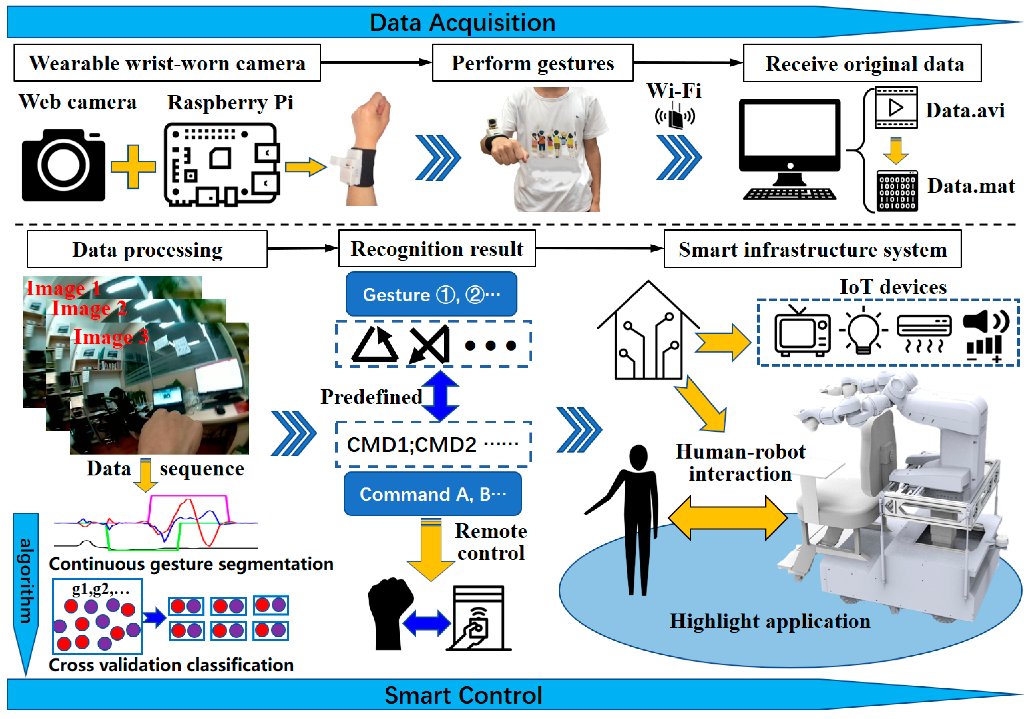
In this article, we propose a novel HMT gesture recognition system based on a wearable wrist-worn camera, and apply it to the intelligent interaction with a nursing-care assistant robot, as shown in Figure 1. To our best knowledge, this is the first study of HMT gesture recognition using a wearable wrist-worn camera based on background velocity analysis, which has no workspace restrictions. In addition, we proposed a reliable method to detect the start/end point of effective HMT gestures for continuous gesture segmentation, which is achieved by detecting the fist motion and the hand motion velocity. Furthermore, we constructed an algorithm framework that is composed of hand region segmentation, background velocity calculation, continuous gesture segmentation, and gesture type classification. We also designed the prototype of an HMT gesture recognition system and carried out experimental verification and results analysis. To further demonstrate the practicability of the proposed system, we designed a prototype of a nursing-care assistant robot for the aged-care at home, and defined 10 special gestures to interact with the nursing-care assistant robot.
The remaining part of this article is organized as follows: the architecture of the wearable wrist-worn camera and the new nursing-care assistant robot are described in Section 2. The algorithm framework for the gesture recognition and the gesture principle designed for the navigation of the nursing-care assistant robot are presented in Section 3. In Section 4, the description of the experimental process and the evaluation of the proposed gesture recognition system are conducted, and the application of the interaction with the nursing-care assistant robot is carried out. Finally, Section 5 gives the discussion and conclusion of our work.

2. System Architecture

The architecture of the HMT gesture recognition system consists of three parts: data acquisition, data processing, and a natural human–robot interface for smart infrastructure. In the data acquisition, the subject puts the wearable wrist-worn camera on their right wrist and performs gestures. The camera records the original video data of the background, which reflects the HMT. After that, the data are transmitted to the host computer through Wi-Fi, and then the data are processed. During data processing, a series of algorithms are used to recognize the hand region, calculate the velocity of the background based on matching the Speeded-Up Robust Features (SURF) feature points, and segment the continuous gesture. Then, the velocity data of the effective gesture are obtained. After that, the classification algorithm is used to recognize the target gesture. The gesture recognition results correspond to the predefined control commands, so that various smart IoT devices in smart homes can be remotely controlled by the gesture. The highlight application of this study is the interaction between human and robot. A nursing-care assistant robot is designed for the assistance of elderly people at home, and the completed prototype can achieve two working modes of the man-in-seat interaction mode and remote interaction mode based on the proposed HMT gesture recognition system.

2.1. The Wearable Camera Architecture

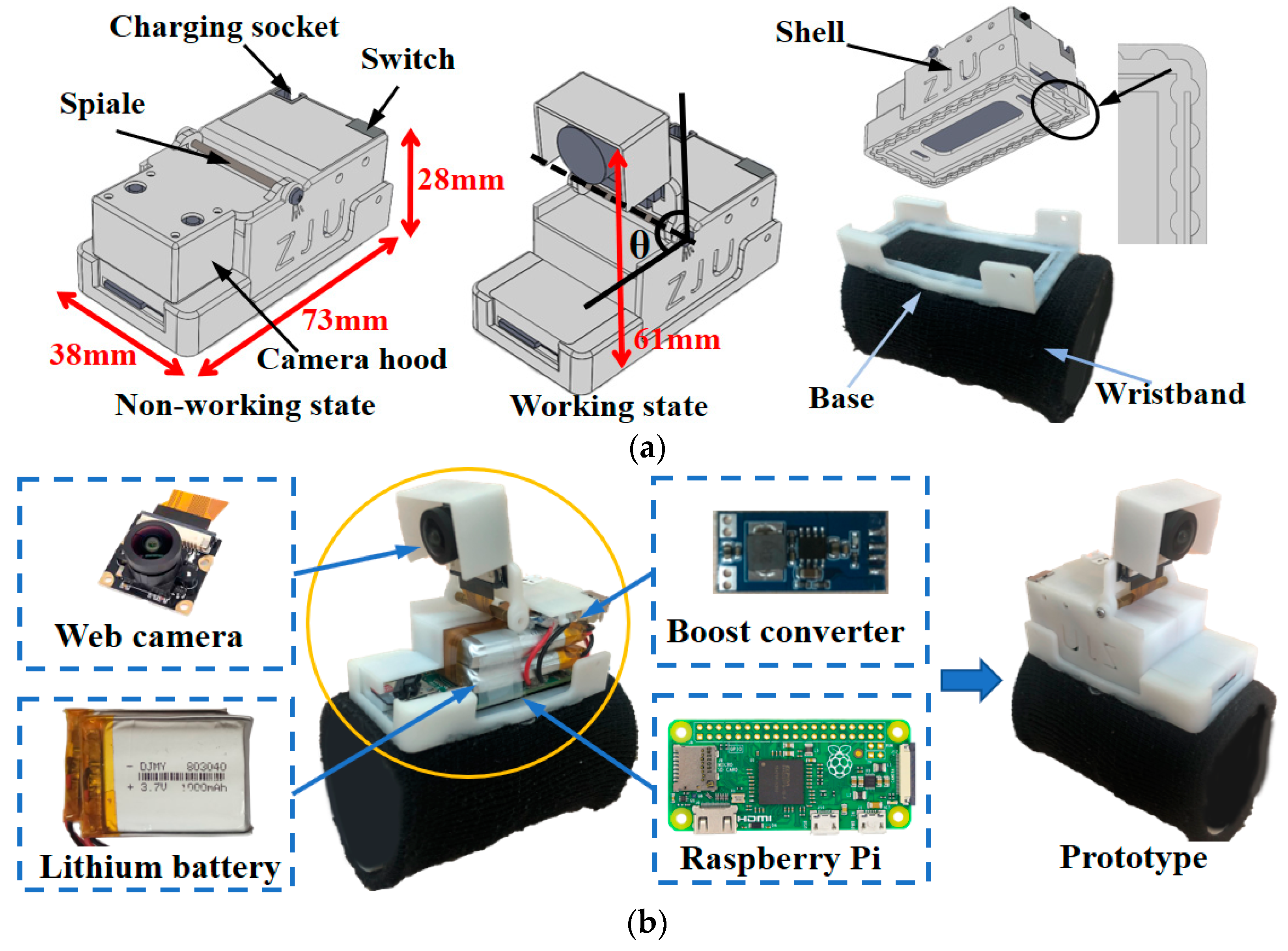
For the HMT gesture recognition in this study, we designed a new wearable wrist-worn camera. The hardware structure is shown in Figure 2. We used SolidWorks to design the lightweight and foldable structures firstly, as shown in Figure 2a. The device is designed according to the requirements of lightweight, unobtrusiveness, and portability, as a wearable device for the daily use of the elderly [26]. The base, shell, and camera hood are all manufactured by the 3D printing of nylon material (the thickness of printing shell is one mm), which has the advantage of being lightweight (the final prototype is 114 g in weight). The foldable structure of the camera partially endows the device with a compact structure. The base and an elastic fabric wristband are bonded by melt adhesive (we use a dispensing gun to heat the melt adhesive and apply the base to the fabric). The mentioned foldable structure guarantees the unobtrusiveness of the device for users. The drawer type structure between the shell and the base is adopted, which can be easily dismantled and installed, and satisfies the user’s usage requirements of portability.
The selected image-based sensor is the Raspberry Pi Camera Module, which is a CMOS-type (Complementary Metal Oxide Semiconductor) 175-degree wide-angle camera that is especially compatible with Raspberry Pi with a resolution of five million pixels (2952 × 1944 pixels). As the control unit, Raspberry Pi Zero W integrates a 1-Ghz single-core central processing unit (CPU) and 512 MB RAM with additional support for 802.11 b/g/n wireless LAN connectivity. The module is suitable for prototype development and the verification of smart infrastructure under the Internet of Things technology due to its small size (65 mm × 30 mm × 5 mm) and wireless transmission compatibility. In addition, compared with other controller modules such as Arduino, it has a higher clock frequency, which is more suitable for fast image processing and acquisition. In order to ensure the small size of the integrated design, the camera module and the Raspberry Pi are connected by a flexible flat cable (FFC). According to the power supply requirement and the size limitation of the integrated design, two rechargeable lithium batteries with a rated voltage of 3.7 V are selected for parallel output with a total capacity of 2000 mAh. Meanwhile, in order to meet the demand of Raspberry Pi and the camera module’s power supply, the boost converter is used to get 5 V of voltage output. The integrated implementation of the wearable wrist-worn camera described above and the prototype are shown in Figure 2b.
In the process of collecting the original video data, the Raspberry Pi runs the python script on the Raspbian system (a system based on Debian GNU/Linux for Raspberry Pi hardware development) to establish the TCP (Transmission Control Protocol) server firstly, and then connects with the TCP client on the computer. After the successful connection, the Raspberry Pi collects the video data from the camera module, and then transmits the video data to the computer with the configuration of 320 × 240 resolution and a frame rate of 12 frames per second (FPS). The above parameters based on experimental optimization can reduce the packet loss and satisfy the data processing requirements of subsequent algorithms. The algorithmic details of data processing will be introduced in detail in Section 3.
The exact size of the wearable camera can be found in Figure 2a. The camera hood is equipped with a camera module, which can rotate 0–150 degrees between the camera hood and the shell through a rotating shaft. There are irregular grooves designed at the bottom of the base for uniform melt adhesive. The angle θ is set to 80 degrees in the working state of this study, and it can be easily folded in the non-working state. The test result showed that the working current is 0.21 A in the video transmission state, and 0.11 A in the boot state without data transmission. According to the battery capacity and actual use test, the device can work continuously for more than four hours, which fully meets the requirements of the use in household conditions [27]. Furthermore, the system power consumption can be further reduced by monitoring the motion velocity threshold that triggers the sleep mode.

2.2. The Nursing-Care Assistant Robot

With the advent of an aging society, many robots, such as mental commitment robots dedicated for mental healing [28] and the smart wheelchairs [29], have been proposed to help on-site caregivers. Mukai et al. developed an assistant robot, RIBA, to lift a human in its arms [
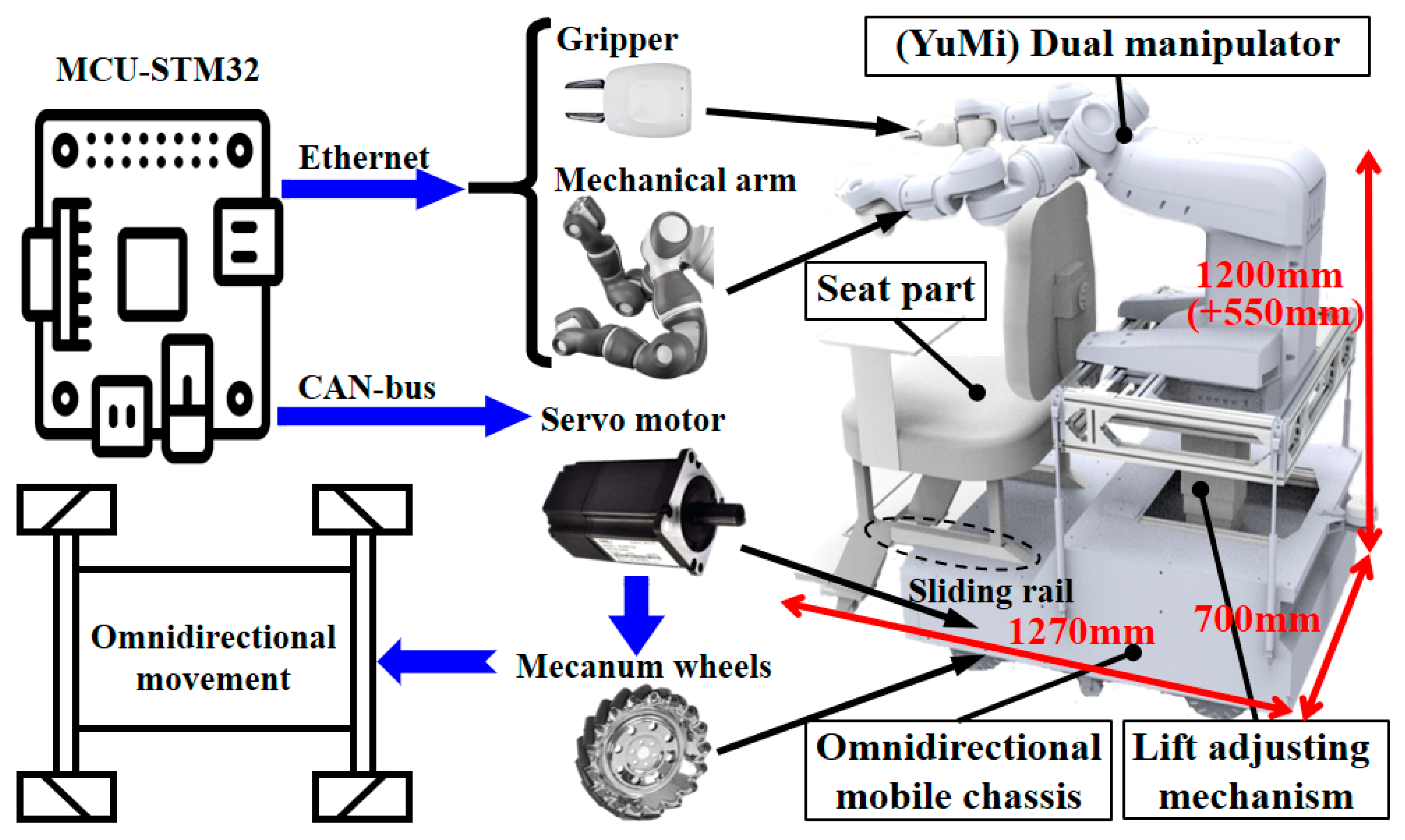
30]. The above nursing robots are mainly oriented toward hospitals and clinics. In this study, we have integrated the design of a nursing-care assistant robot for aged-care at home that can not only carry people similar to a wheelchair, but also grasp the target object. As shown in Figure 3, the mechanical structure of the nursing robot consists of four parts: omnidirectional mobile chassis, lift adjusting mechanism, dual manipulator above the chassis, and the seat part at the fore. The YuMi collaborative robot produced by Asea Brown Boveri Ltd. (ABB) was chosen as the dual manipulator. The frame of the other structures was made of all the aluminum profiles. The design of all of the mechanical structures of this cooperative robot was carried out in SolidWorks. Meanwhile, the corresponding structural stability was checked to ensure the reliability and safety of the household environment. Limited by the length of the article, the details of the check are not carried out in this article; these are provided in the corresponding supplementary materials, Check S1. The dimensions of the robot are shown in Figure 3, where the maximum (550 mm) of longitudinal lift is reflected.
The user can sit on the seat part in front of the nursing cooperative robot, and the dual manipulator makes corresponding nursing actions behind the user such as assisting in helping the user get up from the seat, fetching the target object, and so on. In detail, the robot can move its dual arms to a suitable position providing supporting points such as the chair arms for the elderly to get up from the seat. An electric lifting adjusting mechanism is designed between the dual manipulator and the mobile chassis. The corresponding height between the dual manipulator and the user can be adjusted to adapt to users with different body shapes and ensure the space for the manipulator with different movements. Similarly, the sliding rail mechanism between the seat part and the mobile chassis can adjust the relative distance between the user and the manipulator, which ensures the user’s comfort and a wide application for different people.
As shown in Figure 3, the communication protocol of the nursing-care assistant robot mainly related to the communication between the omnidirectional mobile chassis and the dual manipulator. In this design, the STM32F405RGT6 provided by STMicroelectronics is selected as the microcontroller unit (MCU) in the main control board. The motion control of the dual manipulator is based on the IRC5 controller of ABB. The single manipulator consists of a mechanical arm and a gripper, which is independently communicated with the main control board via Ethernet. The omnidirectional mobile chassis is driven by four servo motors, which are controlled by the corresponding servo motor controller. The Controller Area Network (CAN-bus) communication mode is chosen between the mobile chassis servo controller and the MCU. The nursing-care assistant robot that we proposed is aiming to assist and nurse the elderly at home. Two working modes of the nursing-care assistant robot are designed to better meet the above nursing needs: man-in-seat interaction mode and remote interaction mode. The man-in-seat interaction mode refers to the near-field control. When the user sits on the nursing-care assistant robot’s seat part, this mode realizes the function of assisting the elderly in moving to the designated destination and taking some necessary objects such as medicines. The remote interaction mode refers to the condition that interacts with the robot remotely, which is aiming to assist the elderly in picking up distant objects.

3. Algorithm and Principle

3.1. Algorithm for HMT Gesture Recognition

After obtaining the original video data, MATLAB is used to decode the data for the subsequent processing in the computer. In order to realize continuous HMT gesture recognition, the main idea of our scheme is as follows. The hand in the middle of the captured video footage is almost static, and the feature that can reflect the trajectory of hand motion is the background variation around the hand. We select the velocity of the background as the characteristic parameter, and indirectly reflect the actual hand motion trajectory based on the motion velocity of the background in the video. Secondly, in order to distinguish the effective gestures and other ineffective gestures in the process of continuous hand motion, we used an innovative method to segment gestures by detecting the motion of fist bobbing and the changes of hand motion velocity. The motion of the fist bobbing is defined as flexing and then extending the wrist. Since the size of the fist varies from user to user, the angle of wrist flex varies from person to person. What the user needs to ensure is that the fist disappears from the video screen when the wrist is flexed. It can be more clearly shown by the demonstration video in the supplementary materials, Video S1. After obtaining the effective gesture data, we classify the gestures by cross-validation, and obtain the gesture recognition results. The algorithm flow diagram is shown in Figure 4.
In order to implement the above algorithm framework, we divide the continuous HMT gesture recognition algorithm framework into the following four main steps: (1) hand region segmentation, which can obtain the height feature of the hand; (2) background velocity calculation, which can be obtained by the background feature point matching; (3) continuous gesture segmentation, which is achieved by the start–end signal detection; and (4) data normalization and cross-validation classification, which can obtain the recognition accuracy to evaluate the performance of the system. The algorithm is discussed in detail in the subsections of this section.

3.1.1. Hand Region Segmentation

In the process of continuous gesture recognition, the motion of fist bobbing should be judged by the height change of the hand region. In addition, the foreground area of the hand should be removed, and only the background part should be reserved for subsequent processing when calculating the velocity of the background feature. Therefore, the recognition and segmentation of the hand region is the important part of the algorithm framework. In this subsection, we will describe the algorithms for hand region segmentation and hand height calculation.
In order to improve the efficiency of the algorithm and the recognition velocity of the whole system, we reduced the pixels of the original video frame to 72 × 96 pixels from 240 × 320 pixels before the hand region segmentation. Since the camera module used in this study is a 175-degree wide-angle camera, the original image has a wide-angle distortion effect, as shown in Figure 5a. Generally, the wide-angle distortion can be corrected by the corresponding correction algorithm [31]. However, the hand region is an important parameter in continuous gesture segmentation and background velocity calculation in this study. Particularly, we didn’t use the general wide-angle distortion correction algorithm; instead, we used the pixel reduction method to remove the serious distortion image corner, which results in the pixels being cut down to 54 × 73 pixels, as shown in Figure 5b. This method is very suitable for this study. The serious wide-angle distortion can be eliminated conveniently, and the characteristics of the hand region in the middle of the image are highlighted. At the same time, in order to improve the performance of the subsequent processing algorithm, the red–green–blue (RGB) image is transformed into a L*a*b* color space. The transformation result is shown in Figure 5c. Then, we use the simple linear iterative cluster (SLIC) [32] algorithm, which can generate superpixels to further divide the pixel meshes and reduce the computation cost of hand region segmentation. The result of the SLIC is shown in Figure 5d.
The lazy snapping algorithm [33] is used to realize the segmentation of the hand region, which is an interactive algorithm for image segmentation. The foreground and background are segmented based on the seed pixels specified by the user. In the original video images, the distinction between the foreground and background is more obvious. Obviously, the middle part of the image is the hand region, while the rest is the environmental background. Therefore, the video image sequence is segmented by giving the initial foreground and background seed pixels. As shown in Figure 5e, the green area is the seed pixels of the foreground Sfore(0), and the blue area is the seed pixels of the background Sback(0).
As shown in Figure 5f, the hand region segmentation result Rhand(i) of the current frame can be obtained by giving the Sfore(i−1) and Sback(i−1) of the previous frame. The foreground seed pixels Sfore(i) for the next gesture segmentation are obtained by combining Sfore(0) and the erosion of the segmentation result of the hand region of the current frame Rhand(i). The background seed pixels Sback(i) for the next gesture segmentation are obtained by subtracting the expansion of the segmentation result of the hand region of the current frame Rhand(i) from Sback(0). Therefore, the whole video sequence can obtain the segmentation results of the hand region. After obtaining the segmentation results of the hand region of each frame, which can serve for the background velocity calculation, the hand height H(i) of the current frame can be calculated by the highest pixel of the hand region, which is used for the subsequent continuous gesture segmentation algorithm.

3.1.2. Background Velocity Calculation

In this study, background velocity is the dominant feature reflecting the trajectory of the hand. How to obtain the background velocity in the video image is a problem to be solved after the foreground of the hand region and the background of the environment have been segmented. The acquisition of velocity depends on the selection of reference points. In this study, the Speeded-Up Robust Features (SURF) [34] keypoints are chosen to be the reference points, and the background velocity is obtained by the average displacement of the matched SURF keypoints between two adjacent image frames.
This part of the specific algorithm flow is introduced below. Firstly, the SURF keypoints of two adjacent image frames are extracted, and the keypoints in the foreground are removed according to the segmentation results of the hand region, which results that only the keypoints in the background are retained. As shown in Figure 6a,b, the green plus signs and the red dots are the keypoints extracted from the two adjacent image frames, respectively. Moreover, the corresponding matching distance is calculated by using the method Lowe et al. proposed in [35]. The keypoints obtained from the two adjacent image frames are matched according to the minimum distance, and the matching keypoints whose distance exceeds the threshold Lowe et al. proposed in [35] will be removed.
As shown in Figure 6c, after obtaining the matching keypoints between two adjacent image frames, the displacement of the matching keypoints between two adjacent image frames with that of the frame interval is 1/12 s, according to the above data configuration. The velocity vector of each matching was shown by the yellow arrow in Figure 6c. In order to quantify the background velocity by the velocity vector of the matching points, all of the velocity vectors are represented in the coordinate system, as shown in Figure 6d. The 1/5 maximum and the 1/5 minimum values of the vector components VX and Vy are deemed invalid, which may be affected by the matching at the edge of the image. The invalid values are shown by the pink circle marker in Figure 6d, while the remaining valid values are shown by the blue dot marker. The final velocity values of the current frame are represented by the red plus sign marker in Figure 6d, which was obtained by averaging all of the valid velocity values.

3.1.3. Continuous Gestures Segmentation

One of the focuses in this study is to recognize a series of continuous HMT gestures correspondingly. In order to realize the recognition and classification of the corresponding gestures, it is necessary to distinguish between the effective gestures and the ineffective gestures in the process of continuous hand motion. Two special rules are defined to distinguish the start point and the end point of an effective gesture: The user should perform the fist bobbing before starting an effective gesture and maintain a motionless state for more than half a second after performing an effective gesture. During the algorithm debugging progress, we obtained total of 1000 gesture samples from five subjects at first, and saved the 1000 gestures as the dataset for a gesture segmentation test. The details of the acquisition of the 1000-gestures dataset will be described in detail in Section 4. The specific algorithm flow is introduced as follows.
Due to the instability of the test subjects’ movements, nominal motionless during performing gestures is not completely static, but slightly quivering. In order to define the nominal motionless state, we set the maximum velocity threshold Vt. If the velocity mean of a frame’s last 0.5 s is smaller than Vt, the hand is considered as being in a motionless state in this frame. Half a second is enough for judging according to the mentioned rule after performing an effective gesture. In order to investigate the optimal threshold of Vt for gesture segmentation, we conduct segmentation accuracy tests of the 1000-gestures dataset described above based on five motionless states with five different Vt values from one pixel/image to five pixels/image. The experimental results are shown in Table 1. The best segmentation accuracy can be obtained when Vt is set as three pixels/image. Thus, the threshold is set as three pixels/image to define the motionless state.
As shown in Figure 7, the algorithm flow chart for the segmentation of a triangular trajectory is presented as a sample. Based on the results of the hand region segmentation, we have obtained the variation curve of the height H(i) of the hand region, which reflects the motion of the fist bobbing. The velocity curve, which reflects the hand motion trajectory, was obtained by the SURF keypoints matching. We defined the effective gesture start rule as follows: when the successive descending edge and rising edge appear in the H(i) curve, as shown in the interval S1 in Figure 7, the motion of fist bobbing appears. This indicates that the subsequent green interval-1 may have the start point of an effective gesture. If the velocity curve changes so greatly, it wouldn’t be considered as a motionless state within interval-1; then, the effective gesture starts, as shown in the pink interval-2, which indicates an effective gesture. The intervals S3, S4, and S5 correspond to the three-step straight line trajectory of the complete triangular trajectory gesture, which make up interval-2. A motionless interval, S2, is allowed between interval S1 and interval S3, which starts after the fist bobbing and continues until the effective gesture begins. We set the time-window width of interval-1 to two seconds, which is experimentally optimized. The start signals of the 1000-gestures dataset mentioned above are tested with seven time-window widths of interval-1 from 1000 ms to 4000 ms with a step of 500 ms, as shown in Table 2, and the best corresponding accuracy of gesture segmentation is obtained when the time-window width is set as 2000 ms (2 s). If the motionless interval S2 is longer than the time-window width of interval-1, the effective gesture interval-2 will not appear. That is to say, gestures that start from two seconds after the fist bobbing will be considered invalid.
The above rule defines the start point of the effective gesture. After the gesture is completed, the following rule is defined to determine the end point of an effective gesture: when an effective gesture is completed, we define the motionless state within a certain period of more than half a second as an end signal, as shown in interval S6. Considering that individual differences may have an impact on the duration of the motionless state, we calculated the gesture segmentation accuracies of the 1000-gestures dataset under seven time-window widths of S6 (100 ms, 500 ms, 900 ms, 1000 ms, 1100 ms, 1500 ms, and 1900 ms), as shown in Table 3. The best segmentation accuracy can be obtained when the time-window width S6 is set as 1000 ms (one second); hence, the time-window width of S6 is set as one second for the segmentation of continuous gestures. If the motionless interval’s duration is lower than one second, it will not be judged as an end signal of the gesture. So far, we have completed the definition of the start point and the end point of an effective gesture through which we can achieve the segmentation of the continuous gestures to get a complete velocity curve data of a single gesture. At this time, the single gesture velocity data sequence has been obtained.

3.1.4. Classification

After obtaining the data for a single gesture, it is necessary to identify the corresponding type of the gesture. Since different gestures have different durations and movement speeds, the velocity data of separated single gestures are normalized before classification by linear interpolation and resampling with the number of sampling points setting as 30. After obtaining the normalized data, a dynamic time warping (DTW) [36] algorithm is used to measure the similarity between different gestures. Then, we use three different methods of cross-validation to classify gestures after data acquisition. Finally, we use the k-Nearest Neighbor (kNN) algorithm [37] to classify the input gestures and determine the gesture type. The above algorithms are all implemented in MATLAB.

3.2. Principle for Navigation of a Nursing-Care Assistant Robot

According to the hardware of the nursing-care assistant robot described above, the chassis can move in all directions through different movement combinations of four Mecanum wheels. We defined six kinds of movements of the moving chassis: forward, backward, left, right, clockwise rotation, and counterclockwise rotation. The six movements mentioned above can accomplish the basic actions of omnidirectional movement and the flexible navigation of the robot at home.
In order to interact with the nursing-care assistant robot through HMT gestures, the one-to-one gesture command that corresponds to the movement of the nursing-care assistant robot needs to be defined. We defined 10 corresponding HMT gestures, as shown in Figure 8, for the interaction between the human and the nursing-care assistant robot. Six of them (gestures 1–6) are used for the six kinds of chassis movements mentioned above. In addition, two gestures (gestures 7 and 8) are defined for the acceleration and deceleration, respectively, and gesture 10 is defined for the stop. According to the introduction of the control system of the nursing-care assistant robot, the control of the mobile chassis and the dual manipulator are mutually independent. In order to realize the overall control of the nursing-care assistant robot, we defined gesture 9 for switching the control interface to realize the function of the dual manipulator.

4. Experiments and Results

4.1. Dataset

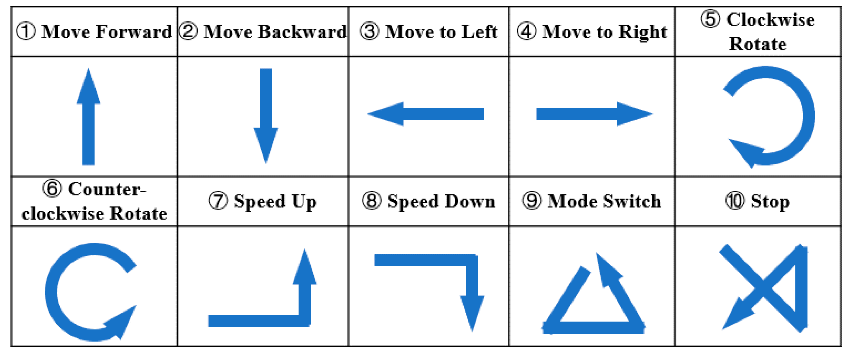
Before the experiment, the approval of the Ethics Committee of the 117th Hospital of People’s Liberation Army of China (PLA) has been obtained, and all of the subjects have signed a consent form. In this study, the performance of the HMT gesture recognition system is tested and verified with five subjects in two postures (sitting and standing); then, we conducted the application on the nursing-care assistant robot by controlling the robot’s movement based on the predefined 10 gestures using the wrist-worn camera.
In order to verify the performance of the gesture recognition system, five subjects of four males and one female, aged from 20–30 with a healthy and movable body, were included in the experiment. In the experiment, the test subjects performed the predefined 10 gestures continuously in one round as a gesture combination. Each subject repeated the gesture combination 10 times in both sitting conditions and standing conditions, respectively. In other words, 200 gesture samples were collected from each subject. Finally, 500 gesture samples were obtained in each condition, and a total of 1000 gesture samples were obtained. During the experiment, the participant put the wearable wrist-worn camera on their right wrist. Then, the camera was positioned to ensure a suitable proportion of the hand area in the image. After that, the participant performed the predefined 10 HMT gestures one by one to collect gesture data following the predefined rules. The participant performed the motion of fist bobbing firstly, and then made the single effective HMT gesture. After finishing a single gesture, the participant needed to maintain a motionless state for more than half a second. The test subjects were guided by the above rules and pretrained to perform the gesture combination once, which was not included as one of the experimental samples to be analyzed. After finishing all of the HMT gestures, the original video data of the gestures were collected and processed to extract the velocity data of the effective single HMT gesture. Then, a DTW algorithm was used for measuring the similarity of the different gestures, and three different methods of cross-validation were used to classify the gestures. The recognition accuracies based on different cross-validation were obtained for the performance verification. After the experiments for performance verification, we applied the HMT gesture recognition system to interact with the nursing-care assistant robot. Similarly, the participant put on the wearable camera to control the nursing-care assistant robot in its man-in-seat interaction mode and remote interaction mode, respectively, based on the predefined 10 gestures. What is different from the experiments in the application is that the HMT gesture recognition is in real time, which is based on a specified training set using a representative method of cross-validation for the classification. The data processing and algorithm verification that were involved in this experiment were all carried out in version 2018a of MATLAB installed on a computer configured with 8 G of memory and 2.6 Ghz CPU.

4.2. Results of the HMT Gesture Recognition

4.2.1. Results of the Continuous Gesture Segmentation

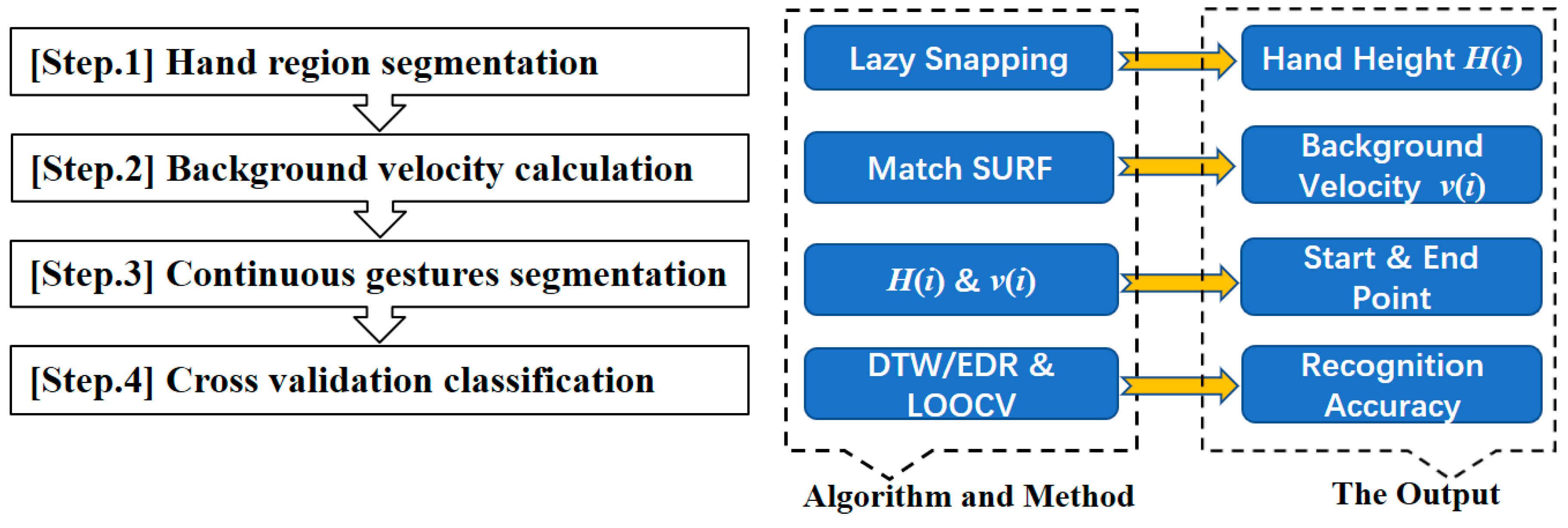
According to the segmentation algorithm of continuous gestures defined in 
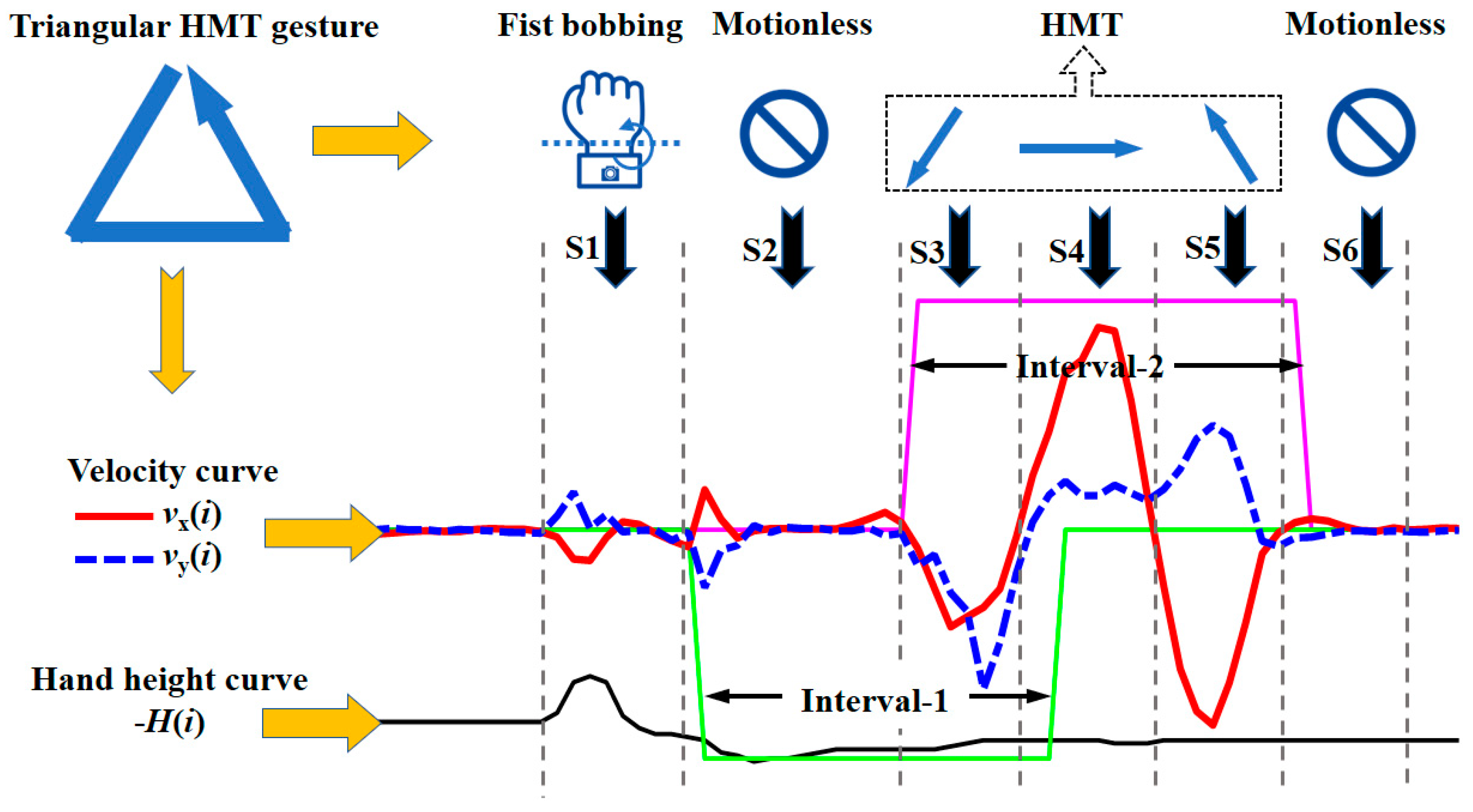
Section 3, 10 consecutive gestures of all of the groups were segmented to extract the effective single gesture. In the experiment, 94 sets of 100 consecutive gestures from the five subjects were segmented into 10 corresponding gestures correctly. The start and end points of the segmentation were also in line with the expectations of the algorithm. Among the six groups of gestures with incorrect segmentation, there were three groups that were caused by the absence of start and end points because of the non-standardized gestures (including the too-small motion of the fist bobbing before the single effective gesture, and the loss of a motionless state after finishing the single effective gesture). The remaining three groups of segmentation errors were caused by the motion of fist bobbing during the process of the effective HMT gesture, which lead to an extra wrong segmentation. Finally, there were 992 gestures completely segmented out of the whole 1000 gestures correctly, which led to a segmentation accuracy rate of 99.20%. The effective gestures that were not correctly segmented were processed manually by specifying the start and end points.

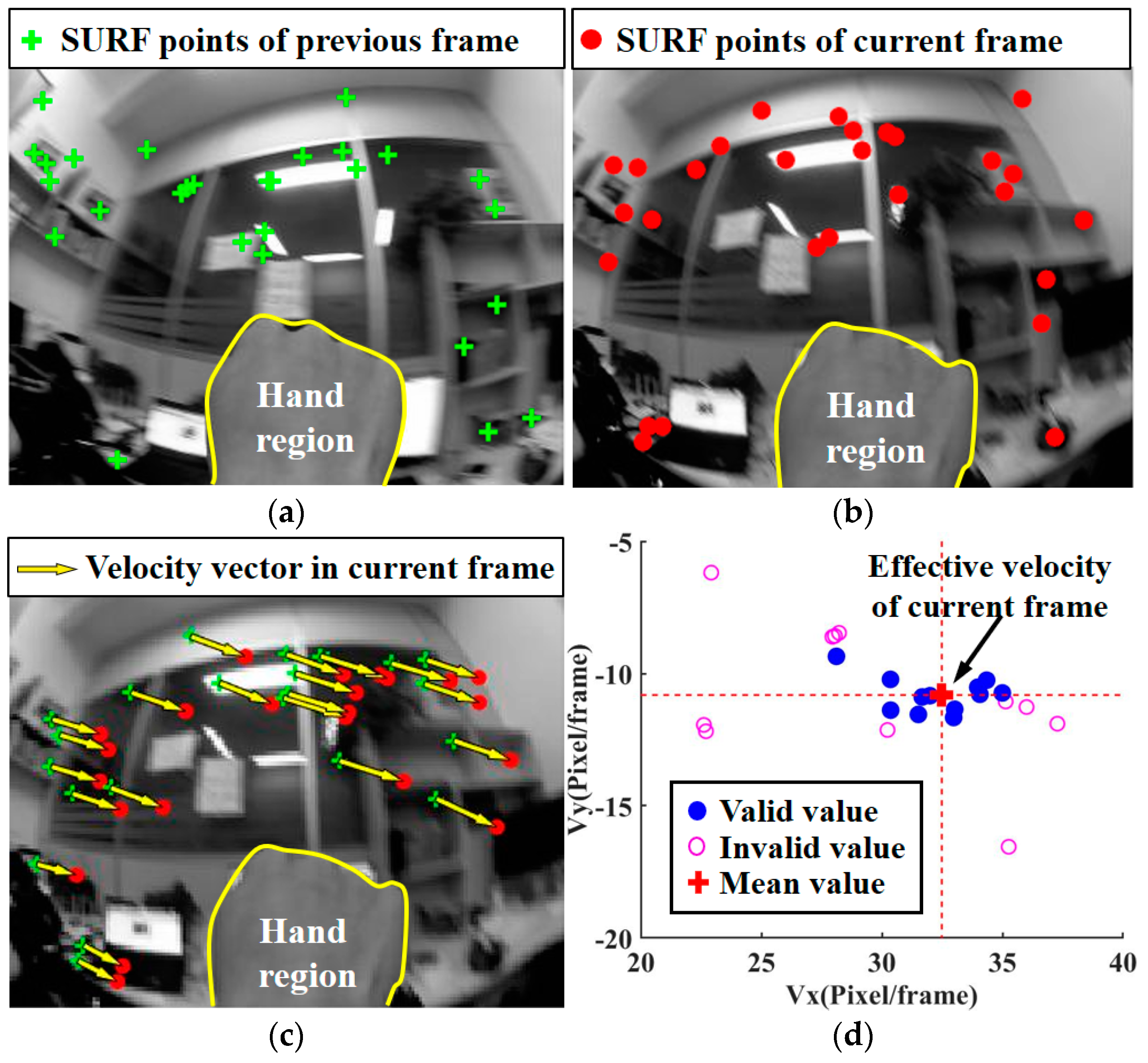
4.2.2. Results of the Background Velocity

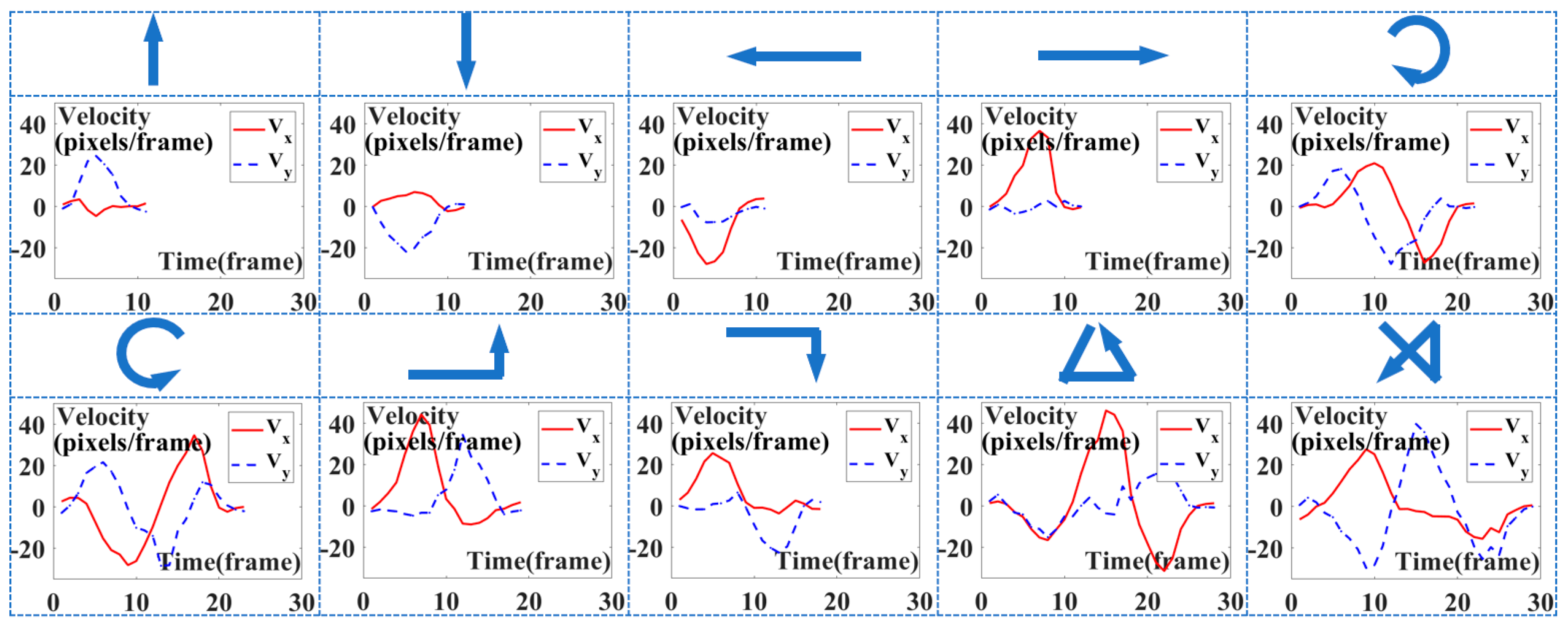
According to the above results of continuous gesture segmentation and the calculation of background velocity based on the matching of the SURF keypoints, a group of the velocity curves of the 10 predefined gestures in this experiment is shown in Figure 9. The velocity curves of VX and Vy are mapped from the background velocity to the gesture trajectory velocity. As seen from the figure, the simple movement between gesture 1 and 4 takes less time to make; the effective gesture action duration is about one second, and the complex movement between gestures 5 and 10 is about twice the simple duration of about three seconds. To reduce the influence of the different lengths of gesture time for classification, all of the hand gesture data were normalized by the method mentioned in Section 3.

4.2.3. Results of the HMT Gesture Recognition

After obtaining the effective velocity data of the corresponding gestures, 1000 gestures were classified with three different cross-validation methods, based on the distance between the velocity data of the corresponding gestures calculated by a DTW algorithm. In order to meet the data requirements of the DTW algorithm, the original velocity data were normalized and resampled with 30 sampling points by linear interpolation before classification.
The three cross-validation methods are introduced as follows: (1) leave-one-subject-out (LOSO) cross-validation is a method that refers to selecting the sample data of one subject as the test set and the sample data of the other subjects as the training set; (2) leave-other-subject-out (LPO) cross-validation refers to selecting the sample data of one subject as the training set and the sample data of the other subjects as the test set; (3) leave-one-group-out within one subject (LOOWS) cross-validation refers to selecting one group of samples from one subject as the test set and the other groups of samples of this subject as the training set. The types of the test gestures were determined according to the shortest distance to the training set based on the DTW algorithm, and the most types that the test gesture was determined to be were taken as the recognition results.
Finally, the accuracies of gesture recognition using different cross-validation methods are shown in Table 4. The mean recognition accuracy with the LOSO cross-validation was up to 97.34%, which verifies the system’s performance in front of an unknown subject. The LPO cross-validation achieved a mean accuracy of 96.55%, which is lower than LOSO, and reflects the variations between different subjects and the diversity of our data. The LOOWS method achieved a mean accuracy of 98%, which is higher than LOSO, and indicates that the user can easily add their characteristic gestures to the system, and the gestures can be recognized efficiently. As shown in Table 4, the HMT gesture recognition accuracies in the standing condition are slightly higher than those in the sitting condition. Besides the random influence of the external environment, the features of the gesture in the standing condition are more evident than those in the sitting condition since the action space in the standing condition is much larger than that in the sitting condition.
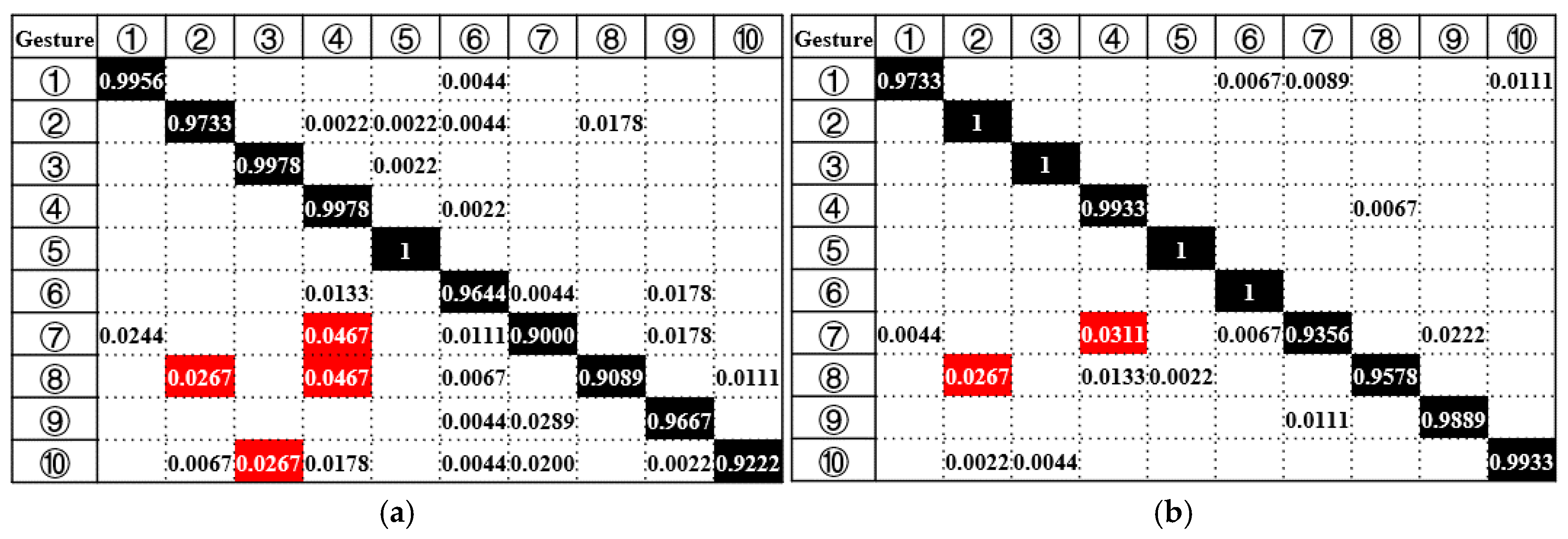
In order to cater for the interactive application of the two interaction modes with the nursing-care assistant robot, the gesture velocity data collected in the standing and sitting conditions based on LOSO cross-validation are analyzed, respectively. The confusion matrices of the recognition results under the two conditions are shown in Figure 10. In addition, the precision, recall, and F-measure of the 10 gestures’ classification are calculated based on the confusion matrix to further verify the performance of the gesture recognition, which are shown in Figure 11. The mean value of the F-measure under the sitting condition is up to 0.984; under the standing condition, it is 0.963. The higher F-measure value in sitting conditions indicates its better classification performance than that in standing conditions.
The overall recognition results of sitting conditions and standing conditions based on LOSO cross-validation are clearly shown from the confusion matrix in Figure 10. Among the confusing gestures, we analyzed the reasons for some having a high proportion of varying classification types. Gesture 7 was classified inaccurately as gesture 4 with the proportion of 4.67% under the sitting condition and 3.11% under the standing condition, because of the missing horizontal motion detection. The missing detection was caused by the incorrect end of a gesture due to the unexpected pauses during a single gesture period. For similar reasons to those mentioned above, gesture 8 was classified inaccurately as gesture 4 with the proportion of 4.67%, and gesture 10 was recognized incorrectly as gesture 2 with the proportion of 2.67%. There is another situation: gesture 8 was classified wrongly as gesture 2 with the proportion of 2.67%, which was caused by the unobvious longitudinal motion in gesture 8. For example, the subjects immediately started the showcased gestures with the uncompleted motion of the fist bobbing, resulting in the insufficient longitudinal motion.

4.3. Interaction with Nursing-Care Assistant Robot

HMT gesture recognition was applied to the intelligent interaction with the nursing-care assistant robot at home. Based on the control system and interaction mode of the nursing-care assistant robot proposed in Section 2, we improved the HTM gesture recognition system to a real-time HMT gesture recognition system, which was more efficient for the interaction application with the robot. Different from the algorithm framework proposed in the theoretical verification part of Section 3, the real-time HMT gesture recognition system’s algorithm framework had the specified training templates based on the LOSO cross-validation, which is more practical and faster during the interaction progress.
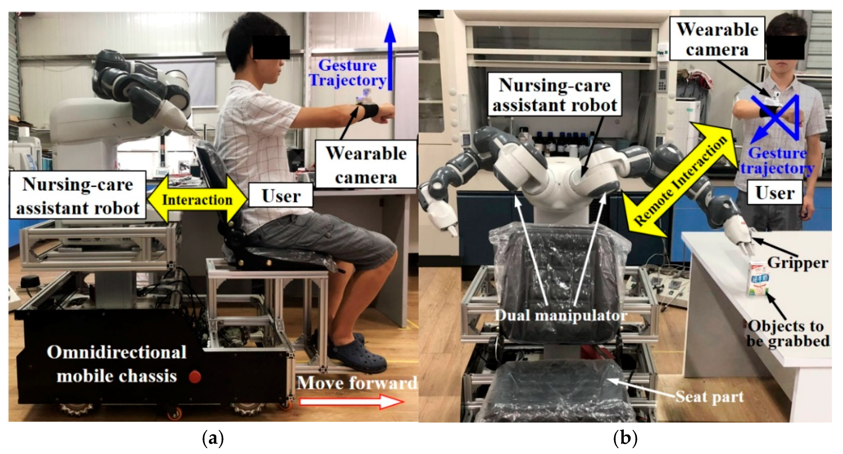
The interaction application with the nursing-care assistant robot was carried out under two different interaction modes of the robot. As shown in Figure 12a, under the man-in-seat interaction mode, the user wore a wearable camera on his right wrist, and sat on the seat part in front of the nursing-care assistant robot. Then, the user made corresponding predefined gestures to guide the robot. Due to the additional background velocity of the robot when the user interacted with the robot in the man-in-seat interaction mode, there was a deviation between the experimental results in sitting conditions and the actual control interaction process in theory. However, the subsequent application shows that this additional velocity hardly affected the recognition accuracy, which illustrates the robustness of the proposed HMT gesture recognition system. The HMT gesture recognition in standing conditions corresponds to the remote interaction mode of the nursing-care assistant robot. The remote interactive state is shown in Figure 12b. The user remotely guides the robot to a specified condition, and then the command mode is switched for the control of the dual manipulator by performing the gesture command. After that, the manipulator is remotely operated to complete the action of assisting in grabbing the specified objects. During the progress of the interaction, the original video data of the gesture collected by the wearable camera is transmitted to the host computer through Wi-Fi for processing and recognition, and the recognition result communicates with the robot’s control system through the predefined control commands corresponding to the predefined HMT gesture.

5. Discussion and Conclusions

In this paper, an innovative HMT gesture recognition system based on background velocity features using a wearable wrist-worn camera was proposed and applied to intelligent interaction with a nursing-care assistant robot. In this study, the environment image data were collected during the user’s hand motion when using a wearable wrist-worn camera. The velocity of the HMT gesture was reflected by background velocity, which was calculated by the displacement of the matching SURF points between adjacent frames. In addition, we defined a reliable rule to segment the continuous gestures by detecting the motion of fist bobbing and the background velocity, and the accuracy of the gesture segmentation reached 99.2% with the 1000 effective gestures that were obtained.
Ten gesture command rules for interacting with the nursing-care assistant robot were defined in this study. More importantly, in order to evaluate the performance of the HMT gesture recognition system proposed in this study, we collected 1000 effective gestures from five test subjects. The gestures’ classification and recognition were achieved using three different cross-validation methods based on the DTW algorithm. The average recognition accuracy of 97.34% is achieved based on the LOSO cross-validation, and the recognition accuracy of gesture recognition in sitting conditions and standing conditions were analyzed and compared. In addition, the application of interaction with the nursing-care assistant robot under the man-in-seat interaction mode and the remote interaction mode were conducted. Furthermore, a demonstration video was made and provided as supplementary material for clear expression.
Although the HMT gesture recognition system that was proposed in this study as a novel recognition method has significantly improved flexibility and reliability compared with the traditional fixed gesture recognition method, there are also some drawbacks to the current work. Although the approach of the fist bobbing detection proposed in this study to segment the effective gestures is reliable, the continuous gesture segmentation algorithm takes a long time due to the hand region segmentation based on the lazy snapping algorithm, which affects the efficiency of the whole algorithm. The algorithm for the hand region segmentation can be improved or replaced in order to reduce the computation time in the future.

Supplementary Materials

The following are available online at https://www.mdpi.com/2076-3417/8/12/2349/s1, Video S1: Human-robot interaction based on HMT gesture recognition using a wearable wrist-worn camera; Video S2: Prior work about the gesture recognition using a smart glove; Check S1: Stability check of the robot.

Author Contributions

H.Y., G.Y., Z.P. and J.Z. provided directional guidance to the research. H.L., Z.P. and G.Y. conceived and designed the experiments. H.L. performed the experiments. H.L. analyzed the data and wrote the paper. F.C., J.W. and G.Y. revised the paper.

Funding

This work has been supported by The National Key R&D Program of China (Grant No. 2017YFB1301203), Fundamental Research Funds for the Central Universities, National Natural Science Foundation of China (Grant No. U1509204), The Science Fund for Creative Research Groups of the National Natural Science Foundation of China (Grant No. 51521064), China’s Thousand Talents Plan Young Professionals Program and Robotics Institute of Zhejiang University (Grant No. K18-508116-008-03).

Conflicts of Interest

The authors declare no conflict of interest.

References

  1. Chang, C.Y.; Kuo, C.H.; Chen, J.C.; Wang, T.C. Design and implementation of an iot access point for smart home. Appl. Sci. 2015, 5, 1882–1903. [Google Scholar] [CrossRef]
  2. Ray, P.P. A survey on internet of things architectures. J. King Saud Univ. Comput. Inf. Sci. 2016, 3, 290–302. [Google Scholar] [CrossRef]
  3. Mukai, T.; Hirano, S.; Yoshida, M.; Nakashima, H. Whole-body contact manipulation using tactile information for the nursing-care assistant robot RIBA. In Proceedings of the IEEE/RSJ International Conference on Intelligent Robots and Systems, San Francisco, CA, USA, 25–30 September 2011; pp. 2445–2451. [Google Scholar]
  4. Xu, D.; Chen, Y.L.; Lin, C.; Kong, X. Real-Time Dynamic Gesture Recognition System Based on Depth Perception for Robot Navigation. In Proceedings of the IEEE International Conference on Robotics and Biomimetics (ROBIO 2012), Guangzhou, China, 11–14 December 2012; pp. 689–694. [Google Scholar]
  5. Portet, F.; Vacher, M.; Golanski, C.; Roux, C.; Meillon, B. Design and evaluation of a smart home voice interface for the elderly: Acceptability and objection aspects. Pers. Ubiquitous Comput. 2013, 17, 127–144. [Google Scholar] [CrossRef] [Green Version]
  6. Güttler, J.; Georgoulas, C.; Linner, T.; Bock, T. Towards a future robotic home environment: A survey. Gerontology 2015, 61, 268–280. [Google Scholar] [CrossRef] [PubMed]
  7. Christian, D.I.; Bürgy, C.; James, H.; Garrett, J.H. Wearable computers: An interface between humans and smart infrastructure systems. Vdi Berichte 2002, 1668, 385–398. [Google Scholar]
  8. Cheng, H.; Dai, Z.; Liu, Z.; Zhao, Y. An image-to-class dynamic time warping approach for both 3D static and trajectory hand gesture recognition. Pattern Recognit. 2016, 55, 137–147. [Google Scholar] [CrossRef]
  9. Corchia, L.; Benedetto, E.D.; Monti, G.; Cataldo, A.; Tarricone, L. Wearable antennas for applications in remote assistance to elderly people. In Proceedings of the IEEE International Workshop on Measurement and Networking, Naples, Italy, 27–29 September 2017; pp. 1–6. [Google Scholar] [CrossRef]
  10. Choi, E.; Kwon, S.; Lee, D.; Lee, H.; Chung, M.K. Can user-derived gesture be considered as the best gesture for a command?: Focusing on the commands for smart home system. Proc. Hum. Factors Ergon. Soc. Annu. Meet. 2012, 56, 1253–1257. [Google Scholar] [CrossRef]
  11. Simão, M.; Neto, P.; Gibaru, O. Natural control of an industrial robot using hand gesture recognition with neural networks. In Proceedings of the IEEE 42nd Annual Conference of the IEEE Industrial Electronics Society, Florence, Italy, 23–26 October 2016. [Google Scholar] [CrossRef]
  12. Austin, E.E.; Sweller, N. Presentation and production: The role of gesture in spatial communication. J. Exp. Child Psychol. 2014, 122, 92–103. [Google Scholar] [CrossRef] [PubMed]
  13. Chen, F.; Deng, J.; Pang, Z.; Nejad, M.B.; Yang, H.; Yang, G. Finger angle-based hand gesture recognition for smart infrastructure using wearable wrist-worn camera. Appl. Sci. 2018, 8, 369. [Google Scholar] [CrossRef]
  14. Yang, G.; Deng, J.; Pang, G.; Zhang, H.; Li, J.; Deng, B.; Pang, Z.; Xu, J.; Jiang, M.; Liljeberg, P. An iot-enabled stroke rehabilitation system based on smart wearable armband and machine learning. IEEE J. Transl. Eng. Health Med. 2018, 6, 1–10. [Google Scholar] [CrossRef] [PubMed]
  15. Elmezain, M.; Al-Hamadi, A. Gesture recognition for alphabets from hand motion trajectory using hidden markov models. In Proceedings of the 8th IEEE International Symposium on Signal Processing and Information Technology, ISSPIT 2008, Sarajevo, Bosnia and Herzegovina, 16–19 December 2008; pp. 1192–1197. [Google Scholar] [CrossRef]
  16. Katsuki, Y.; Yamakawa, Y.; Ishikawa, M. High-speed human/robot hand interaction system. In Proceedings of the HRIACM/IEEE International Conference on Human-Robot Interaction System, Portland, OR, USA, 2–5 March 2015; pp. 117–118. [Google Scholar] [CrossRef]
  17. Liu, H.; Wang, L. Gesture recognition for human-robot collaboration: A review. Int. J. Ind. Ergon. 2016. [Google Scholar] [CrossRef]
  18. Han, J.; Shao, L.; Xu, D.; Shotton, J. Enhanced computer vision with Microsoft Kinect sensor: A review. IEEE Trans. Cybern. 2013, 43, 1318–1334. [Google Scholar] [PubMed]
  19. Xu, R.; Zhou, S.; Li, W.J. Mems accelerometer based nonspecific-user hand gesture recognition. IEEE Sens. J. 2012, 12, 1166–1173. [Google Scholar] [CrossRef]
  20. Xie, R.; Sun, X.; Xia, X.; Cao, J. Similarity matching-based extensible hand gesture recognition. IEEE Sens. J. 2015, 15, 3475–3483. [Google Scholar] [CrossRef]
  21. Plouffe, G.; Cretu, A.M. Static and dynamic hand gesture recognition in depth data using dynamic time warping. IEEE Trans. Instrum. Meas. 2016, 65, 305–316. [Google Scholar] [CrossRef]
  22. Tang, J.; Cheng, H.; Zhao, Y.; Guo, H. Structured dynamic time warping for continuous hand trajectory gesture recognition. Pattern Recognit. 2018. [Google Scholar] [CrossRef]
  23. Zhang, Z.; Tian, Z.; Zhou, M. Latern: Dynamic continuous hand gesture recognition using FMCW radar sensor. IEEE Sens. J. 2018, 18, 1. [Google Scholar] [CrossRef]
  24. Wachs, J.P.; Kölsch, M.; Stern, H.; Edan, Y. Vision-based hand-gesture applications. Commun. ACM 2011, 54, 60–71. [Google Scholar] [CrossRef]
  25. Kim, D.; Hilliges, O.; Izadi, S.; Butler, A.D.; Chen, J.; Oikonomidis, I.; Olivier, P. Digits:Freehand 3D interactions anywhere using a wrist-worn gloveless sensor. In Proceedings of the ACM Symposium on User Interface Software and Technology (UIST), Cambridge, MA, USA, 7–10 October 2012; pp. 167–176. [Google Scholar] [CrossRef]
  26. Knecht, K.; Bryan-Kinns, N.; Shoop, K. Usability and design of personal wearable and portable devices for thermal comfort in shared work environments. In Proceedings of the 20th Annual Healthcare Internet Conference (HCIC), Pajaro Dunes, Watsonville, CA, USA, 26–30 June 2016; p. 41. [Google Scholar] [CrossRef]
  27. Sivanathan, A.; Sherratt, D.; Gharakheili, H.H.; Sivaraman, V.; Vishwanath, A. Low-cost flow-based security solutions for smart-home IoT devices. In Proceedings of the 10th IEEE International Conference on Advanced Networks and Telecommunication Systems (ANTCS), Odisha, India, 6–9 November 2016. [Google Scholar] [CrossRef]
  28. Wada, K.; Shibata, T.; Saito, T.; Tanie, K. Psychological and social effects in long-term experiment of robot assisted activity to elderly people at a health service facility for the aged. In Proceedings of the IEEE/RSJ International Conference on Intelligent Robots and Systems (IROS), Hamburg, Germany, 28 September–2 October 2004; Volume 3063, pp. 3068–3073. [Google Scholar] [CrossRef]
  29. Mandel, C.; Luth, T.; Laue, T.; Rofer, T. Navigating a smart wheelchair with a brain-computer interface interpreting steady-state visual evoked potentials. In Proceedings of the IEEE/RSJ International Conference on Intelligent Robots and Systems, St. Louis, MO, USA, 10–15 October 2009; pp. 1118–1125. [Google Scholar] [CrossRef]
  30. Mukai, T.; Hirano, S.; Nakashima, H.; Kato, Y. Development of a nursing-care assistant robot riba that can lift a human in its arms. In Proceedings of the IEEE/RSJ International Conference on Intelligent RObots and Systems (IROS), Taipei, Taiwan, 18–22 October 2010; pp. 5996–6001. [Google Scholar] [CrossRef]
  31. Ai, S.; Wang, X.; Ma, M.; Wang, K. A method for correcting non-linear geometric distortion in ultra-wide-angle imaging system. Optik 2013, 124, 7014–7021. [Google Scholar] [CrossRef]
  32. Achanta, R.; Shaji, A.; Smith, K.; Lucchi, A.; Fua, P.; Susstrunk, S. Slic superpixels compared to state-of-the-art superpixel methods. IEEE Trans. Pattern Anal. Mach. Intell. 2012, 34, 2274–2282. [Google Scholar] [CrossRef] [PubMed]
  33. Li, Y.; Sun, J.; Tang, C.K.; Shum, H.Y. Lazy snapping. ACM Trans. Graph. 2004, 23, 303–308. [Google Scholar] [CrossRef]
  34. Li, J.; Wang, Y.; Wang, Y. Visual tracking and learning using speeded up robust features. Pattern Recognit. Lett. 2012, 33, 2094–2101. [Google Scholar] [CrossRef]
  35. Lowe, D.G. Distinctive image features from scale-invariant keypoints. Int. J. Comput. Vis. 2004, 60, 91–110. [Google Scholar] [CrossRef]
  36. Paliwal, K.K.; Agarwal, A.; Sinha, S.S. A modification over Sakoe and Chiba’s dynamic time warping algorithm for isolated word recognition. Signal Process. 1982, 4, 329–333. [Google Scholar] [CrossRef]
  37. Gou, J.; Ma, H.; Ou, W.; Zeng, S.; Rao, Y.; Yang, H. A generalized mean distance-based k-nearest neighbor classifier. Expert Syst. Appl. 2019, 115, 356–372. [Google Scholar] [CrossRef]
Figure 1. The flow-process diagram of the proposed hand motion trajectory (HMT) gesture recognition system based on the wearable wrist-worn camera for application in the smart infrastructure.
Applsci 08 02349 g001
Figure 2. (a) Concept design of the wearable wrist-worn camera with an emphasis on wearability and user’s comfort; (b) Integrated implementation of the wearable wrist-worn camera.
Applsci 08 02349 g002
Figure 3. Concept design of the nursing-care assistant robot consisting of an omnidirectional mobile chassis, lift adjusting mechanism, dual manipulator, and the seat part. The communication protocol of the robot control system is shown as well.
Applsci 08 02349 g003
Figure 4. The algorithm flow diagram of the continuous HMT gesture recognition.
Applsci 08 02349 g004
Figure 5. The processing of video image for hand region segmentation: (a) Original red–green–blue (RGB) image; (b) Image after compressing and cutting pixels; (c) RGB image is transformed into L*a*b* color space; (d) The superpixels result of the simple linear iterative cluster (SLIC) algorithm; (e) Seed pixels of the foreground and background for the lazy snapping algorithm; (f) The result of hand region segmentation using the lazy snapping algorithm.
Applsci 08 02349 g005
Figure 6. Speeded-Up Robust Features (SURF) keypoints are extracted, and the average displacement of matching keypoints between the adjacent frames was used to characterize the velocity of background. (a) The extracted SURF keypoints of the previous image frame; (b) The extracted SURF keypoints of the current image frame; (c) The matching keypoints between adjacent image frames; (d) Determination of the effective values of current frame’s velocity.
Applsci 08 02349 g006
Figure 7. Description of the continuous gesture segmentation principle based on the process of a triangular HMT gesture.
Applsci 08 02349 g007
Figure 8. Ten predefined gestures for the interaction between human and nursing-care assistant robot.
Applsci 08 02349 g008
Figure 9. Velocity curves sample of the 10 predefined HMT gestures.
Applsci 08 02349 g009
Figure 10. (a) Confusion matrix of gesture recognition in sitting conditions; (b) Confusion matrix of gesture recognition in standing conditions.
Applsci 08 02349 g010
Figure 11. (a) The precision, recall, and F-measure of gesture classification in sitting conditions; (b) The precision, recall, and F-measure of gesture classification in standing conditions.
Applsci 08 02349 g011
Figure 12. The implementation of the interaction with the nursing-care assistant robot: (a) Man-in-seat interaction mode of the nursing-care assistant robot; (b) Remote interaction mode of the nursing-care assistant robot.
Applsci 08 02349 g012
Table 1. Segmentation accuracy of continuous gestures with different values of Vt.
Vt (pixels/image)12345
Segmentation accuracy (%)83.197.199.298.397.8
Table 2. Segmentation accuracy with different time-window widths of interval-1.
Interval-1 (ms)1000150020002500300035004000
Segmentation accuracy (%)90.499.099.298.998.596.558.2
Table 3. Segmentation accuracy with different time-window widths of interval S6.
Interval S6 (ms)1005009001000110015001900
Segmentation accuracy (%)98.198.698.899.298.798.396.9
Table 4. Gesture recognition accuracies using three cross-validation methods with five subjects. LOSO: leave-one-subject-out, LPO: leave-other-subject-out, LOOWS: leave-one-group-out within one subject.
PostureSiting ConditionStanding ConditionMean
Subject12345Mean12345Mean
Recognition Accuracy (%)LOSO97.3396.7893.6897.8995.6796.2799.6798.1796.4499.3398.4898.4297.34
LPO96.5697.5693.7897.3394.6795.9899.3797.5694.4498.4497.5697.4796.55
LOOWS97.6790.0010010010097.5398.3310094.0010010098.4798.00

