Communication

Wireless Power Transfer System Based on Strapping Resonators

Institute of Applied Physics, University of Electronics Science and Technology of China, Chengdu 610054, China
*
Author to whom correspondence should be addressed.
Appl. Sci. 2018, 8(12), 2341; https://doi.org/10.3390/app8122341
Submission received: 23 October 2018 / Revised: 17 November 2018 / Accepted: 19 November 2018 / Published: 22 November 2018
(This article belongs to the Section Applied Physics General)

Abstract

:
In this study, a kind of strapped resonator is proposed to deal with high power wireless power transfer (WPT) in microwave regimes. In many specific applications, such as high power microwave wireless power transfer system (WPT), a coil resonator is not suitable due to the frequency limitations. The high cost of the high-permittivity dielectric resonators also limits their application. As a high Q resonator, the strapped resonator is often used in the anode structure of a magnetron. The field distribution of π and π + 1 modes allow the system to operate in dual-frequency mode. Numerical simulation and experimental validation show that with a certain distance, the system provides power transfer efficiency of more than 80% and 70% at 630 MHz and 970 MHz, respectively. Compared to the system based on dielectric resonators, the proposed system has higher power capacity. The leakage and radiation loss of the system is also discussed using numerical methods.

Graphical Abstract

1. Introduction

Wireless power transfer (WPT) was first proposed by Tesla in the 19th century [1]. However, this idea did not draw the attention of researchers for nearly a century. Since the end of the 20th century, with the rapid development of electronic technology, a variety of consumer electronic products and medical electronic equipment has appeared in people’s daily lives. These electronic devices are usually highly dependent on their power supplies. In many cases, wired charging is limited in convenience. Thus, in recent years, the concept of WPT has been revisited by researchers, and several WPT systems have been reported [2]. According to the transmission mechanism, there are three options for the wireless power transfer system [3,4,5,6]. The first mechanism uses antenna or array to radiate electromagnetic waves with high power to the far field [4]. This method is suitable for long-distance WPT. The second way is based on the law of electromagnetic induction, which uses the electromagnetic induction between the metal coils to achieve wireless power transfer [5]. The third way is to use the coupling between the resonators [6,7]. Generally, electromagnetic resonance coupling is suitable for high-frequency near-field WPT. It depends on the magnetic–electric coupling between two high-Q resonators. For example, a group from Massachusetts Institute of Technology(MIT) demonstrated that WPT efficiency can be enhanced via resonant coupling [3]. Since then, after years of development, many scientific researchers have been attracted to this concept [8,9,10,11,12,13]. Several solutions based on various types of resonators have been proposed to deal with the most pressing problems of improving efficiency and transmission distance, and meaningful results were obtained. However, in many specific applications, such as high power WPT in microwave regime, coil resonators cannot meet the requirements [13]. In addition, the dielectric resonator (DR) is also limited in high power WPT, due to its large temperature drift [2,14]. Therefore, resonators with higher power capacity and low temperature drift are the key to solving the above problems. In this paper, we explore a structural model based on non-dielectric resonance for WPT in order to overcome the limitations mentioned above. In the new method, a strapped resonator (SR) with four vanes is designed and fabricated. The SR is often used as the anode of high power electric vacuum devices. It has the advantages of high quality factor, low temperature drift and high power capacity [15]. Usually, the internal space of the SR is divided into several sub-cavities by the vanes. When the SR resonates at the fundamental mode, the phase difference of the electric field between adjacent sub-cavities is π. Therefore, the fundamental mode is also called π mode. The first high-order mode is called π + 1 mode [15]. Compared to the DR, the SR has higher mode separation [16]. The unique resonant characteristics of the strapped resonator ensure the wireless power transfer system operates in multiple modes [15]. The field distribution of the two resonant modes (π mode and π + 1 mode) facilitates the coupling between the resonators to achieve efficient WPT. Therefore, the strapped resonator provides a new option for high power near-field WPT systems.

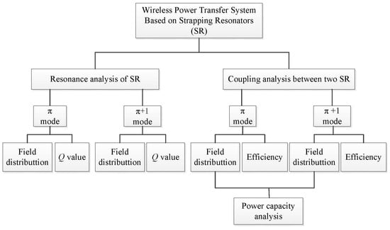
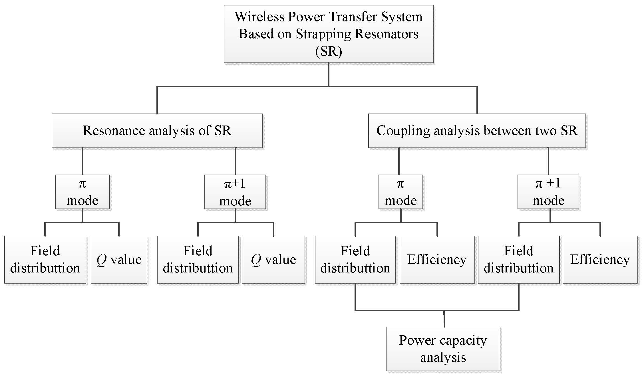
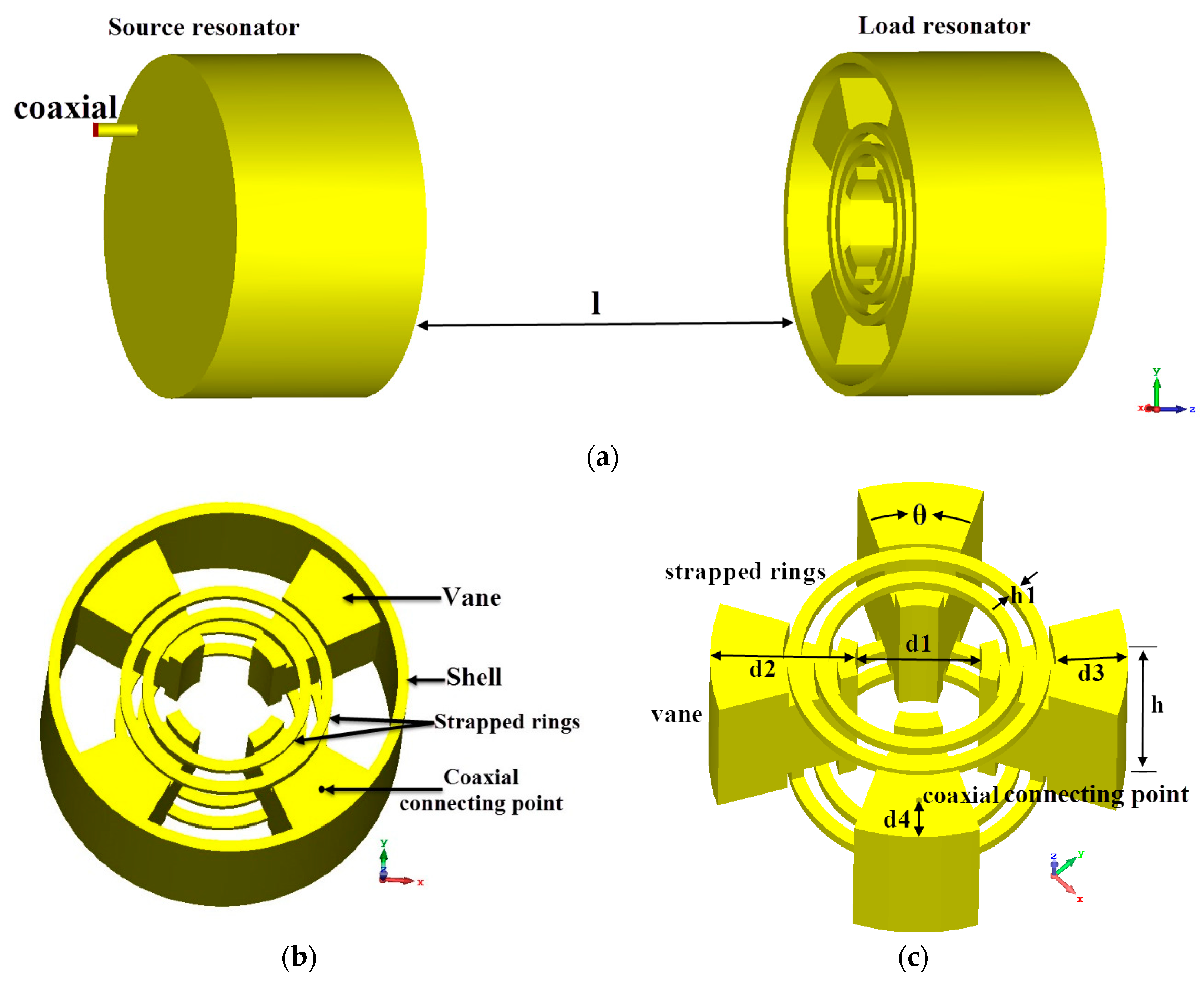
2. Analysis of the Strapped Resonator

The WPT system based on strapped resonators (SR) is shown in Figure 1a. The system consists of two strapped resonators. The distance between the source resonator and load resonator is l. One coaxial probe is used to excite the source resonator, while another one is used to receive the power from the load resonator. Figure 1b shows the structure of the SR. The structure of the SR consists of three parts. The first part is a metal shell. The second part consists of four metal vanes that divide the interior of the structure into four sub-cavities. The third part consists of two pairs of strapped rings, which connect the four vanes alternately. The strapped ring can improve the mode separation so that the resonant frequency of fundamental mode is far away from the resonant frequency of high-order mode. Figure 1c shows the internal structure of a single strapped resonator. The details of the single SR are shown in Table 1.
The resonance characteristics of the strapped resonator are investigated using numerical simulation. Eigen-mode simulations are carried out by commercial software CST (Computer Simulation Technology) Microwave Studio. In the simulation model, to calculate the unloaded quality factor Q0, the material of the SR is set to be oxygen-free copper (with electrical conductivity of 3.56e + 007 S/m). The frequency of the fundamental resonant mode is 0.65 GHz. The field distribution of the fundamental mode is shown in Figure 2. As shown in Figure 2a,b, in the adjacent sub-cavities, the fields have the same amplitude but opposite direction. The phase difference of the oscillations in the two adjacent sub-cavities is π. Thus, the fundamental mode is named as π mode.
Figure 2c,d illustrate the electric and magnetic fields from longitudinal view. The magnetic field distributes away from the center of the structure and its direction is axial. In contrast, the electric field distribution is closer to the center of the structure and its direction is radial. Therefore, with proper excitation, the strapped resonator can exhibit a strong π mode magnetic resonance. The field distribution characteristics of the π mode are suitable for transferring power from one resonator to another through magnetic coupling.
Figure 3 illustrates the electromagnetic field distributions of the first higher mode (π + 1 mode) from the longitudinal section view. The π + 1 mode field between two adjacent cavities is continuous. The directions of the magnetic fields in adjacent cavities are the same. Unlike the π mode, the π + 1 mode does not exhibit significant magnetic resonance or electrical resonance. When the system operates at π + 1 mode, mixed coupling will play the major role in wireless power transfer.
The quality factor of the strapped resonators are also analyzed, since they are directly related to the transfer efficiency of the system.
The quality factor of a resonator is defined as [17],
Q = ω 0 W P l o s s  
In practice, the resonator is coupled to other components which will have an effect on the overall Q. So the quality factor Q can be also expressed as,
Q = ω 0 W P i _ l o s s + P e _ l o s s  
where ω0 is the resonant angular frequency, W is the average stored energy in the resonator, Pi_loss is the power lost inside the resonator, Pe_loss is the power coupled to outside the resonator. Disregarding external loading effects, the unloaded quality factor is defined as,
Q 0 = ω 0 W P i _ l o s s  
In a metal cavity resonator, Pi_loss is the power dissipated in the cavity walls and Pe_loss is the power coupled to outside of the resonator.
Regarding external loading effects, the external quality factor can be expressed as,
Q e = ω 0 W P e _ l o s s  
The value of Q0 will decrease as Pi_loss increases, while the value of Qe decreases as the external coupling of the resonator increases. The values of Q0 and Qe is generally different. The value of Q0 is difficult to measure but can be calculated by Eigen-mode simulation. The value of Qe can be obtained by measurement.
The values of Q0 of the π and π + 1 modes are calculated to be 450 and 700, respectively. To obtain Qe, a strapped resonator is fabricated and tested. A coaxial probe is used to excite the π mode and π + 1 mode resonances. By adjusting the position of the coaxial probe, the best impedance matching can be achieved with d4 = 8.5 mm. The Qe factor is calculated using group delay [17],
Q e = 1 2 π f r τ r  
where fr is the resonant frequency and τr is the reflected group delay at the resonant frequency. Both of them can be measured using a vector network analyzer (VNA). As shown in Figure 4, the resonant frequency and reflected group delay of the strapped resonator are measured using a VNA (E8361A, from Agilent). The measured results are shown in Figure 5. Two reflection zeroes at fπ = 650 MHz and fπ+1 = 970 MHz mark the resonant frequencies of the π and π + 1 modes, respectively. The corresponding group delays at the two resonant frequencies are 81 ns and 181 ns. The values of Qe are calculated to be 82 and 275 according to Equation (5).

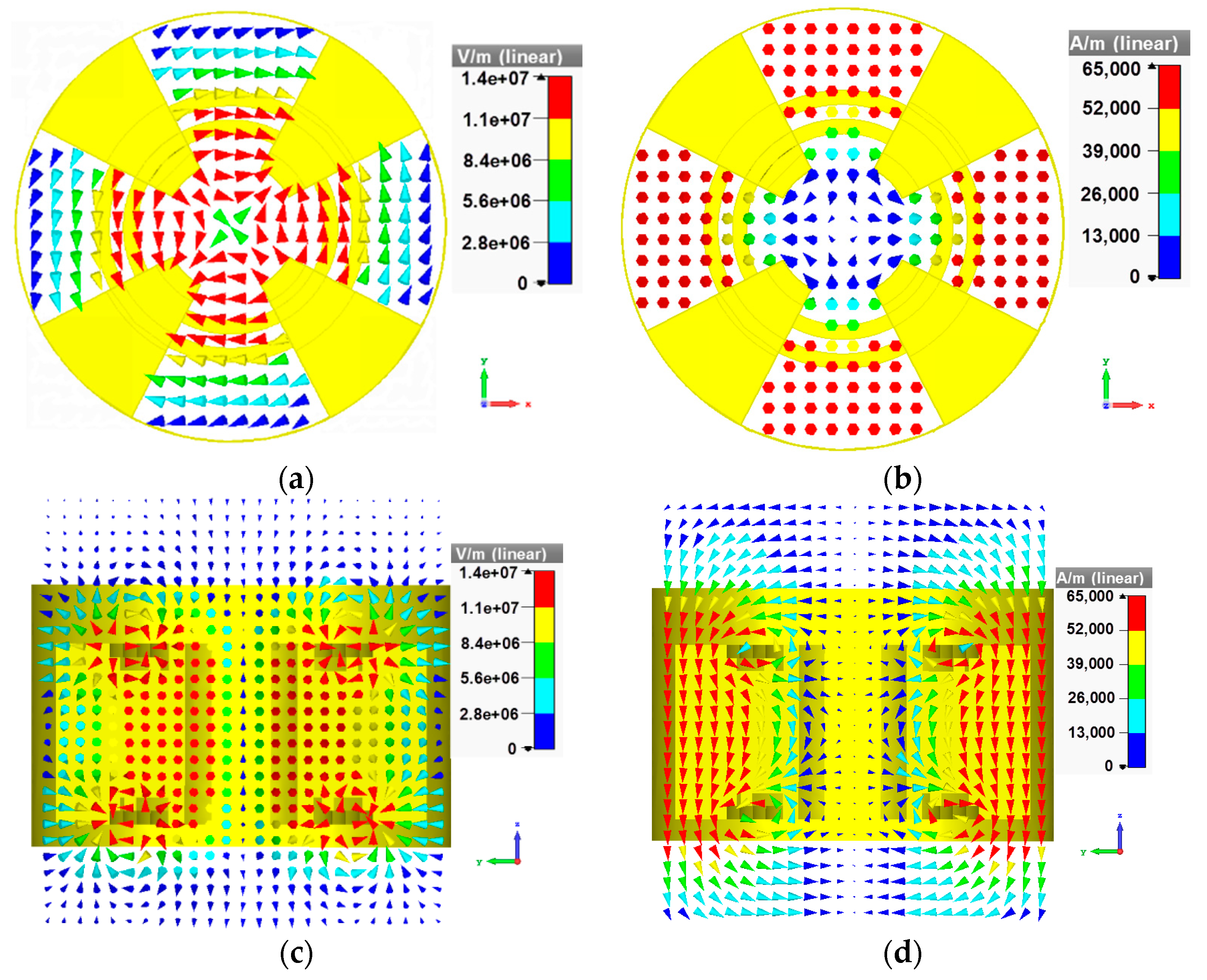
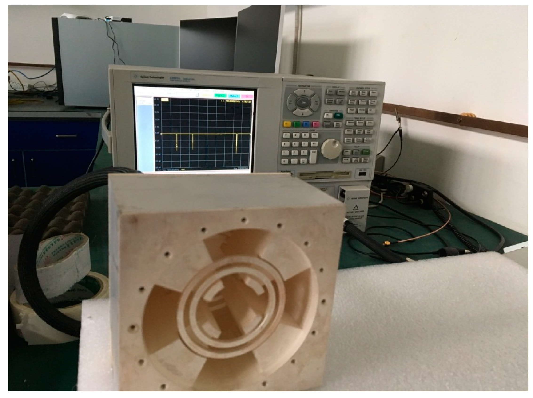
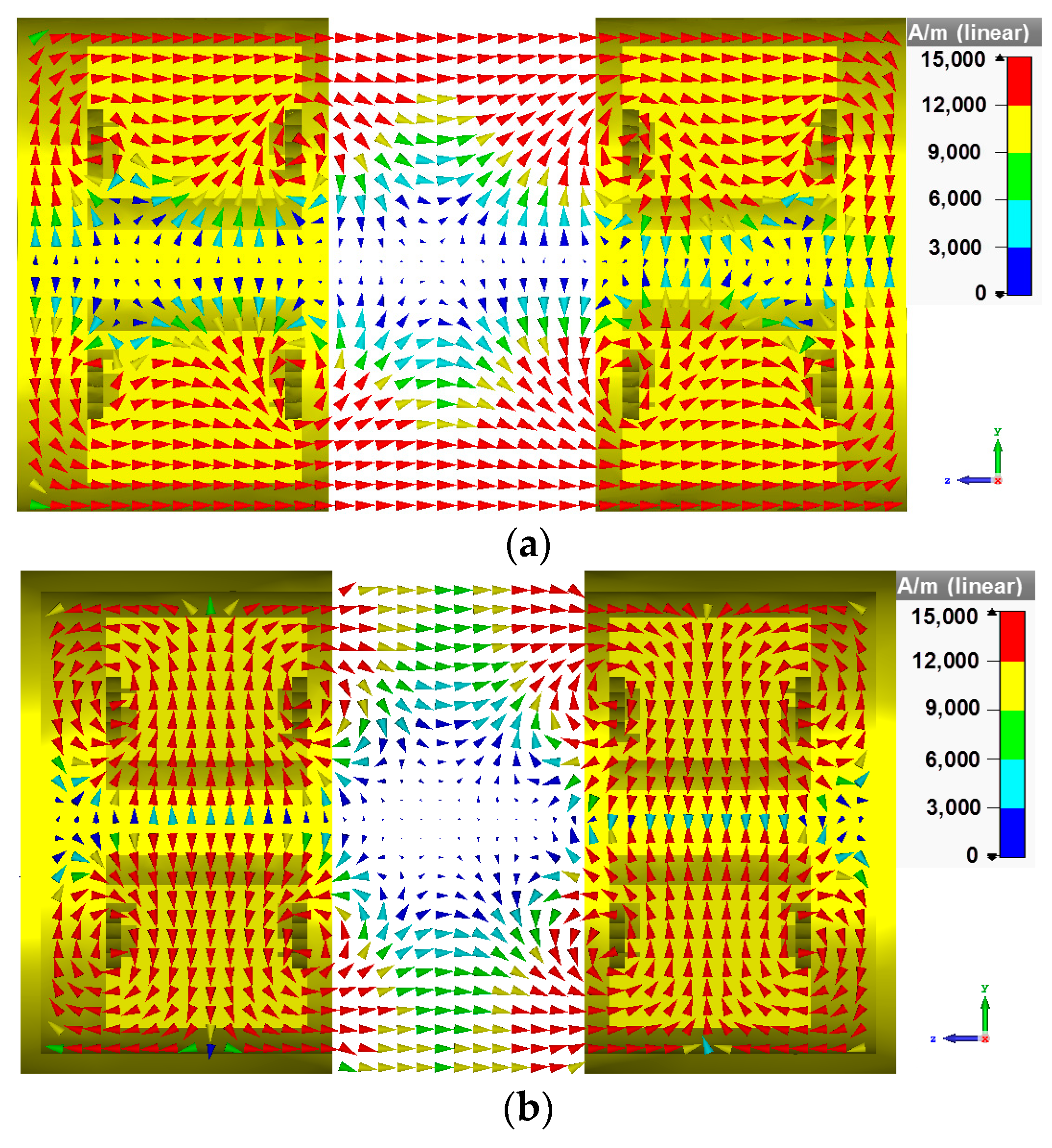
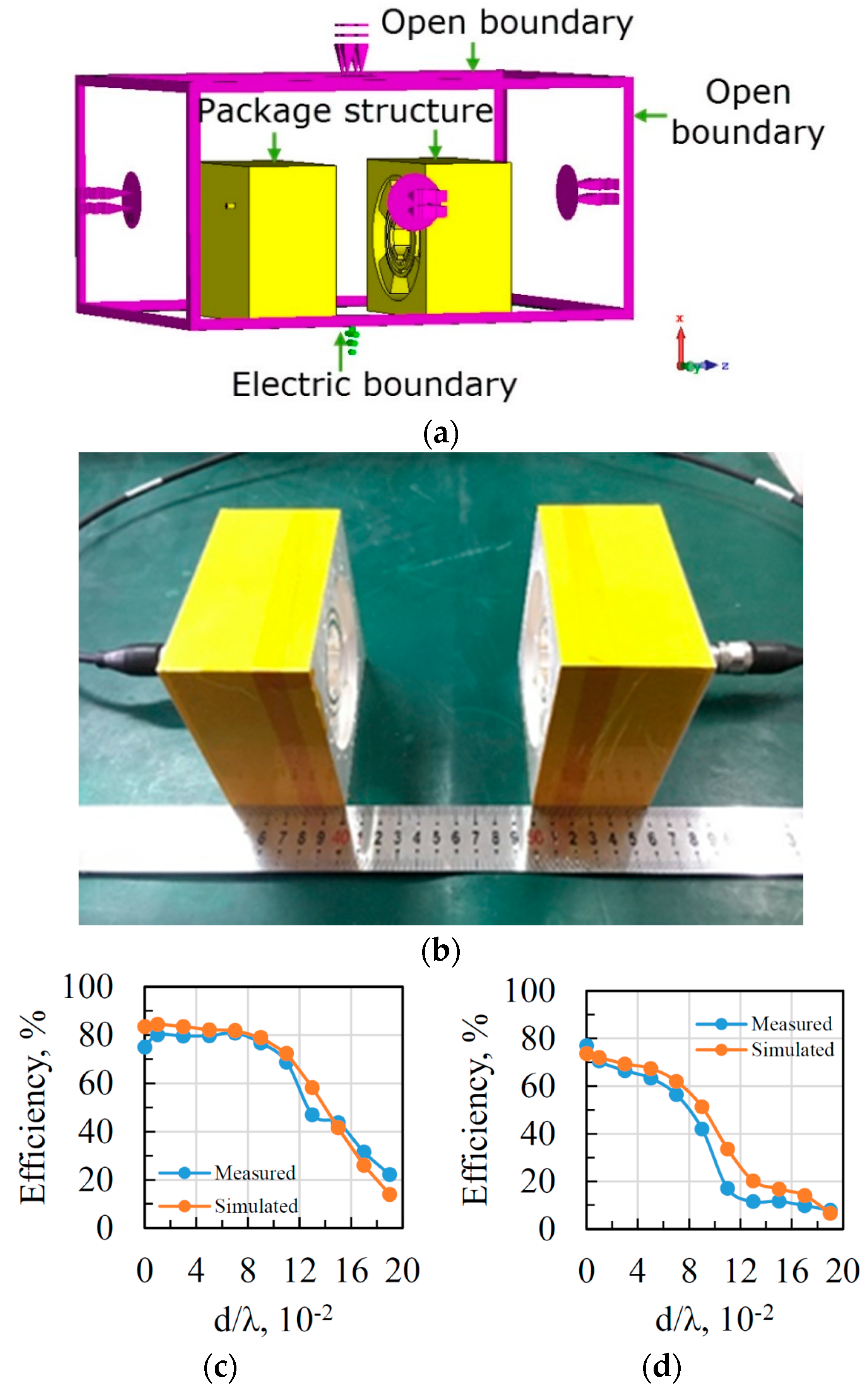
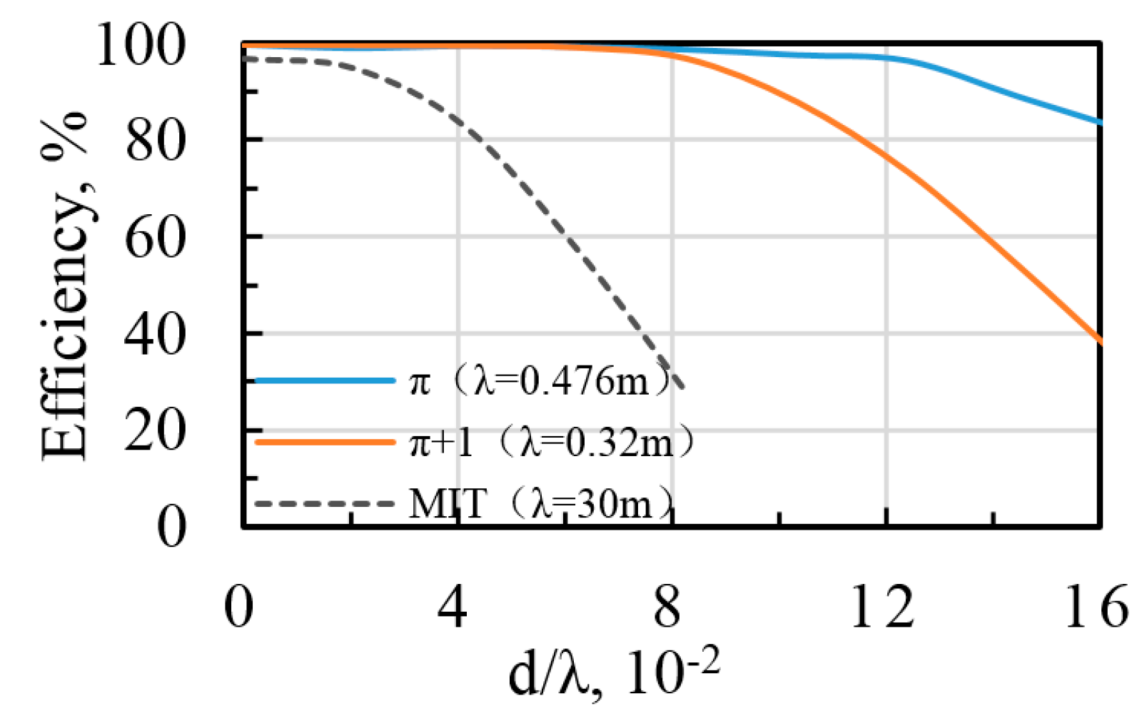
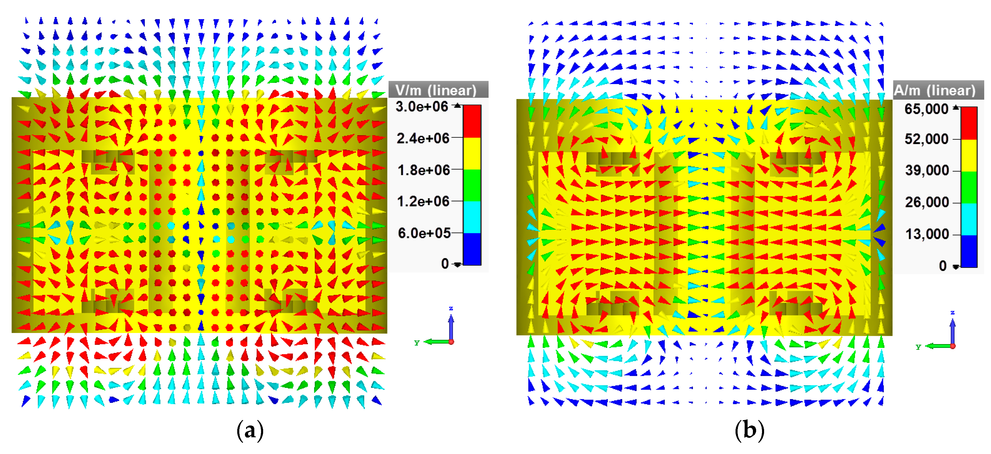
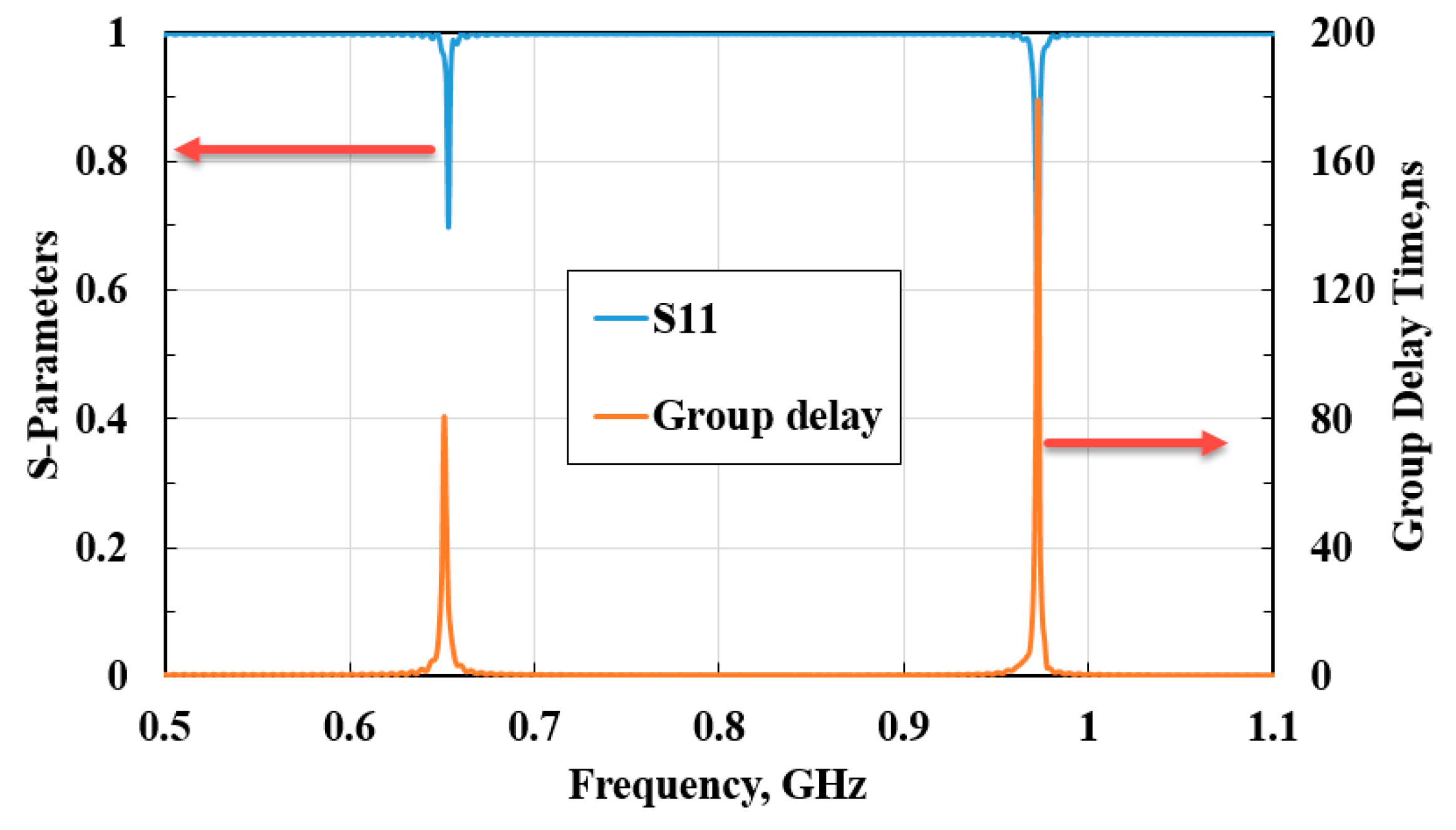
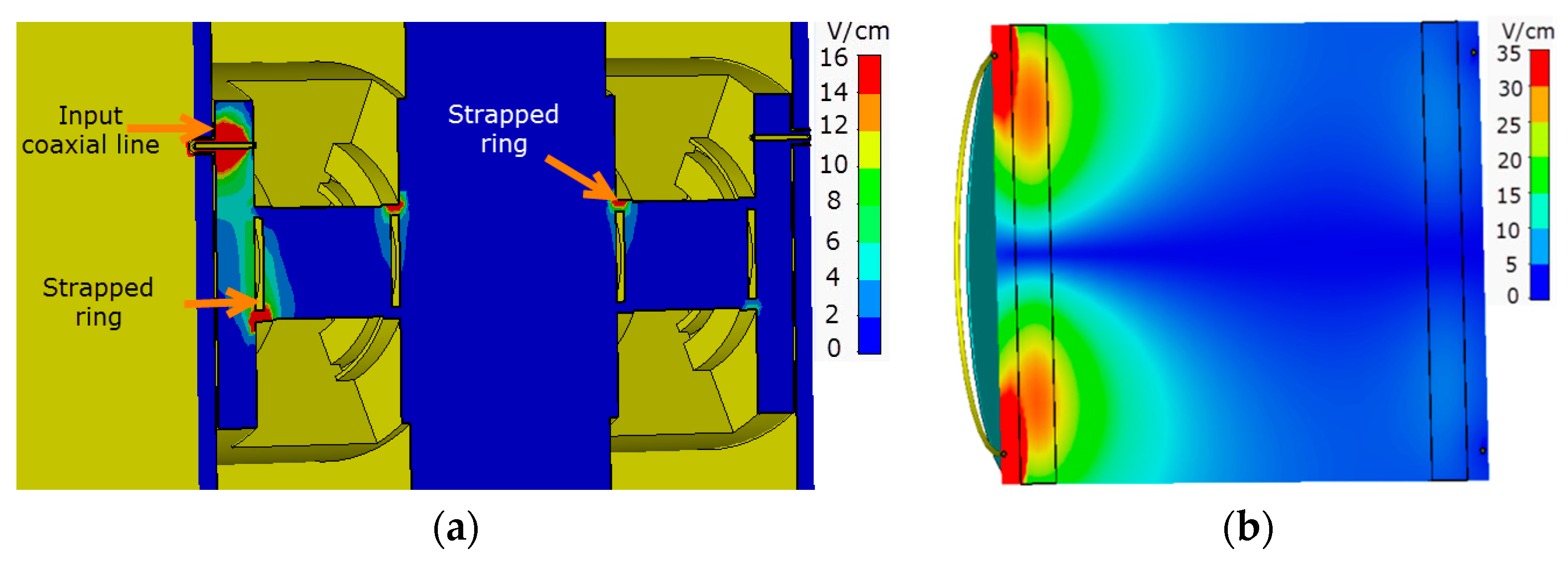
3. Simulation and Experiment Results

The performance of the proposed WPT system based on SR was numerically simulated and experimentally validated. Figure 6 illustrates the magnetic field distribution in the system. When the system is operating at the π mode, the resonators are primarily coupled by magnetic field. The working state of the system operating at the π + 1 mode is shown in Figure 6b. As shown in Figure 6b, part of the energy can also be coupled from the source resonator to the load resonator by magnetic field.
A simulation model for WPT is established as shown in Figure 7a. Referring to Figure 1a, the experimental setup is shown in Figure 7b. Two resonators are connected to a vector network analyzer (VNA) by coaxial lines. In order to get more convincing simulation results, both test environment and package structure of the SR shown in Figure 7b are taken into account in the model. In terms of the S parameters, the efficiency of the system can be calculated by,
η = | S 21 | 2 1 | S 11 | 2  
where S21 is the transmission coefficient and S11 is the reflection coefficient. Figure 7c,d illustrate the WPT efficiency in different operation modes. The measured results closely match the simulated results. When the system operates in the π mode, the efficiency is over 80%, while in the π + 1 mode, the efficiency of the system can still reach 70%.
From simulation and experiment results, both of π and π + 1 modes can be used for WPT with high efficiency. However, as shown Figure 6, it is obvious that the system stability of the π mode is better than π + 1 mode due to stronger coupling in the π mode resonant magnetic field. As shown in Figure 2b, the magnetic field of the π mode is axially distributed throughout the resonator. When the system operates at the π mode, the coupling is weakly affected by the distance within a certain range. Therefore, the system stability is stronger.

4. Discussion

The comparison of the proposed system and the system proposed by MIT’s group is carried out using numerical simulation. In simulation, the material of the resonators is set to be perfect conductor (PEC) to eliminate the metal loss. Thus, in the simulation, the efficiency is only impacted by leakage and radiation loss. To compare the WPT systems working at different frequencies, the distance was normalized by the corresponding operational wavelengths. As shown in Figure 8, it is obvious that the WPT system based SR operating at the π mode and the π + 1 mode shows great advantage towards MIT’s systems [3]. In 0 < d/λ < 2, the efficiency of the operation modes of the proposed system is about 5% higher than MIT’s system. In 2 < d/λ < 8, the efficiency of the proposed system is still stable above 90%, but the efficiency of MIT’s system drops from 82% to 30%.
The power capacity of the proposed system is also investigated using simulation. Both dielectric resonator (DR) and metal cavity resonator have high power capacity. They can operate and can be applied in high power WPT in microwave regime.
The maximum electric fields in each system are shown in Figure 9 when the operating frequency (650 MHz) is the same. The electric field of the systems are excited by a signal with an average power of 1W. The maximum electric field in the proposed system is distributed around the input coaxial line and the strapped rings with an amplitude of 16 V/cm, while the maximum electric field in the system based on DR is distributed between the feeding structure and the source resonator with an amplitude of 35 V/cm. To achieve the breakdown voltage of air [18,19], the input power of the proposed system should be 1800 W, while the input power of the DR system must be higher at 950 W. Therefore, the power capacity of the proposed system is 94% higher than the DR system.
From the perspective of cost, the SR is made of metal and is inexpensive to manufacture compare to DR. In addition, the metal resonator is easy to package and integrate with high power devices.

5. Conclusions

A WPT system based on strapped resonators was proposed in this paper. With the proper excitation, two resonance modes, the π and π + 1 modes, can be excited inside the strapping resonator, which allows the WPT system to operate in dual-frequency mode. For the π mode, the efficiency of the WPT system can reach over 80%, while for the π + 1 mode, the efficiency can still reach 70%. Compared with MIT’s work, the proposed system has the benefit of less leakage and radiation loss. Compared with the system based on DR with high dielectric constants, the system also has the advantages of higher power capacity and lower cost.

Author Contributions

All authors contributed equally to the research work and its final dissemination as an article in its current form.

Funding

This work was funded by the National Natural Science Foundation of China (Grant No. 61601087).

Conflicts of Interest

The authors declare no conflict of interest.

References

  1. Brown, W. The history of power transmission by radio waves. IEEE Trans. Microw. Theory Tech. 1984, 32, 1230–1242. [Google Scholar] [CrossRef]
  2. Jiang, C.; Chau, K.T.; Liu, C.; Lee, C.H.T. An Overview of Resonant Circuits for Wireless Power Transfer. Energies 2017, 10, 894. [Google Scholar] [CrossRef]
  3. Kurs, A.; Karalis, R.; Moffatt, R.; Joannopoulos, J.; Fisher, P.; Soljacic, M. Wireless power transfer via strongly coupled magnetic resonances. Science 2007, 317, 83–86. [Google Scholar] [CrossRef] [PubMed]
  4. Li, Y.; Jandhyala, V. Design of retrodirective antenna array for short-range wireless power transmission. IEEE Trans. Antennas Propag. 2012, 60, 206–211. [Google Scholar] [CrossRef]
  5. Ahn, D.; Hong, S. A study on magnetic field repeater in wireless power transfer. IEEE Trans. Ind. Electron. 2013, 60, 360–371. [Google Scholar] [CrossRef]
  6. Liu, X.; Wang, G. A Novel Wireless Power Transfer System with Double Intermediate Resonant Coils. IEEE Trans. Ind. Electron. 2016, 63, 2174–2180. [Google Scholar] [CrossRef]
  7. Song, M.Z.; Lorsh, L.; Kapitanova, P.; Nenasheva, E.; Belov, P. Wireless power transfer based on magnetic quadrupole coupling in dielectric resonators. Appl. Phys. Lett. 2016, 108, 023902. [Google Scholar] [CrossRef]
  8. Cannon, B.L.; Hoburg, J.F.; Stancil, D.D.; Goldstein, S.C. Magnetic resonant coupling as a potential means for wireless power transfer to multiple small receivers. IEEE Trans. Power Electron. 2009, 24, 1819–1825. [Google Scholar] [CrossRef]
  9. Lu, Y.; Ma, D.B. Wireless Power Transfer System Architectures for Portable or Implantable Applications. Energies 2016, 9, 1087. [Google Scholar] [CrossRef]
  10. Chabalko, M.J.; Sample, A.P. Three-Dimensional Charging via Multimode Resonant Cavity Enabled Wireless Power Transfer. IEEE Trans. Power Electron. 2015, 30, 6163–6173. [Google Scholar] [CrossRef]
  11. Seo, D.W.; Lee, J.H. Frequency Tuning Method Using the Reflection Coefficient in a Wireless Power Transfer System. IEEE Microw. Wirel. Compon. Lett. 2017, 27, 959–961. [Google Scholar] [CrossRef]
  12. Wang, W.; Hemour, S.; Wu, K. Coupled Resonance Energy Transfer Over Gigahertz Frequency Range Using Ceramic Filled Cavity for Medical Implanted Sensors. IEEE Trans. Microw. Theory Tech. 2014, 62, 956–964. [Google Scholar] [CrossRef]
  13. Tran, D.H.; Vu, V.B.; Choi, W. Design of a High-Efficiency Wireless Power Transfer System with Intermediate Coils for the On-Board Chargers of Electric Vehicles. IEEE Trans. Power Electron. 2018, 33, 175–187. [Google Scholar] [CrossRef]
  14. Nenasheva, E.A.; Kartenko, N.F.; Gaidamaka, I.M.; Trubitsyna, O.N.; Redozubov, S.S.; Dedyk, A.I.; Kanareykin, A.D. Low loss microwave ferroelectric ceramics for high power tunable devices. J. Eur. Ceram. Soc. 2010, 30, 395–400. [Google Scholar] [CrossRef]
  15. Collins, G.B. Microwave Magnetrons; McGraw-Hill: New York, NY, USA, 1948; Section 3; pp. 84–88. [Google Scholar]
  16. Ding, S.; Jia, B.F.; Li, F.; Zhu, J.J. 3-D simulation of 5.8 GHz magnetron. J. Electromagn. Waves Appl. 2008, 22, 1925–1930. [Google Scholar] [CrossRef]
  17. Pozar, D.M. Microwave Engineering, 4th ed.; John Wiley & Sons, Inc.: New York, NY, USA, 2012; Section 3; pp. 84–88. ISBN 978-0-470-63155-3. [Google Scholar]
  18. Ding, S.; Jia, B.F.; Li, F.X.; Han, S.H. Power capacity research in cavity bandpass filters. J. Electromagn. Waves Appl. 2008, 22, 905–914. [Google Scholar] [CrossRef]
  19. Jang, S.R.; Ryoo, H.J.; Ahn, S.H. Development and optimization of high-voltage power supply system for industrial magnetron. IEEE Trans. Ind. Electron. 2012, 59, 1453–1461. [Google Scholar] [CrossRef]
Figure 1. Wireless power transfer (WPT) system based on strapped resonator (SR): (a) Coupling model, (b) structure of strapped resonator, and (c) details of the strapped resonator.
Applsci 08 02341 g001
Figure 2. Field distributions of the π mode: (a) Electric field distribution from the cross-sectional view, (b) magnetic field distribution from the cross-sectional view, (c) electric field distribution from the longitudinal section view, and (d) magnetic field distribution from the longitudinal section view.
Applsci 08 02341 g002
Figure 3. Electromagnetic field distribution of π + 1 mode from the longitudinal section view: (a) Electric field distribution, (b) magnetic field distribution.
Applsci 08 02341 g003
Figure 4. Measurement of the reflection characteristic of the strapped resonator.
Applsci 08 02341 g004
Figure 5. Measurement results.
Applsci 08 02341 g005
Figure 6. Coupling between two resonators: (a) Magnetic coupling for the π mode, (b) magnetic coupling for the π + 1 mode.
Applsci 08 02341 g006
Figure 7. Experimental setup and results: (a) Simulation model, (b) experimental setup, (c) WPT efficiency for the π mode, and (d) WPT efficiency for the π + 1 mode.
Applsci 08 02341 g007
Figure 8. Relationship between radio power transmission efficiency and distance.
Applsci 08 02341 g008
Figure 9. Electric field distribution (a) Field distribution in the system based on SR. (b) Electric field distribution in the system based on DR.
Applsci 08 02341 g009
Table 1. Dimension parameters of the strapped resonator. SR: strapped resonator.
ParameterUnitValueDescription
θdegree35aperture angel of the vane
hmm40height of the vane
h1mm3width of the strapped ring
d1mm28inner diameter of the SR
d2mm32length of the vane
d3mm16position of the strapped ring connecting point
d4mm8.5position of the coaxial connecting point
lmm35distance between source resonator and load resonator

