1. Introduction
1.1. Current Photovoltaic and Solar Thermal Systems
Sustainable technology, especially for solar energy, is a key topic all over the world. Solar energy is an important and clean energy that has been used for energy saving and green building in recent years. Researchers have conducted a series of studies and experiments in the field of photovoltaic, solar thermal, and solar power generation. Engineers have carried out some engineering projects and designed some solar engineering systems in the field of solar energy. Therefore, solar energy will be used for different areas and become the most popular energy for humans in the future. Photovoltaic and solar thermal technologies have been considered as key points and used for heating systems by some experts.
Arkar et al. [
1] presented thermal response modeling of a solar heating system that included latent heat storage and an air vacuum tube solar collector. The research results showed that a solar heating fraction of 63% could be obtained in an efficient lightweight building. Martinopoulos et al. [
2] analyzed the economic and technical aspects of a representative solar space and water heating system that was designed based on the newest Greek regulations toward nearly zero energy buildings (NZEB). For all study situations, the solar heating system met more than 45% of the whole heating load and the payback period was not more than 4.5 years, with an annual decrease of more than 50 tons of CO
2 under the worst conditions. Stefano et al. [
3] reviewed solar heat pump systems by technical and economic analysis for identified heating systems. The analysis showed that there was a tendency for a decreased payback period for solar heat pump systems with increased solar resources and decreased heating degree days. Research on solar-assisted heating systems that met the energy demand of buildings and their effect on the energy characteristics of different types of buildings were carried out by Thygesen [
4]. The study concluded that the current incentive mechanism was useless according to the specific energy demand reduction of buildings
1.2. Current Air-Conditioning Systems
Summer means high temperature and humidity in most parts of China. Southern China is a subtropical place with long, hot, and humid summers. Traditional building air-conditioning systems use cold coils to solve sensible heat and latent heat loads. However, the efficiency of these air-conditioning systems and the efficiency of removing steam from condensation is low. The supply air temperature is also a typical problem. Generally, the dry-bulb temperature of the supply air is close to the saturation state (90% to 95% relative humidity) at about 14–15 °C, which consumes additional energy for the precise air-conditioning control system. In order to achieve the goal of energy saving, it is necessary to sacrifice indoor temperature and humidity conditions for the precise air-conditioning control system. The indoor air temperature tends to be 23–26 °C in summer in most areas of China, but the relative humidity is relatively high, which leads to poor indoor air quality. This state easily produces common air-conditioning diseases or sub-health status for humans, and it is easy to discharge large amounts of pollution. To enhance indoor air quality and the effectiveness of air-conditioning systems, many experts have considered dedicated ventilation and fresh air systems as a research hotspot and applied them to air-conditioning systems.
Chen et al. [
5] carried out a series of studies on the effectiveness of dedicated dry cooling ventilation systems to decouple dehumidification from cooling and meet the demands of indoor conditions. The results illustrated that the effectiveness of a dedicated dry cooling ventilation system was most affected by the space-sensible heat ratio and chilled water flow rate and little affected by the outdoor conditions. Wu et al. [
6] simulated an independent dedicated heat pipe ventilation system and set up a control model of flow and temperature fields. The results showed the precision of the numerical simulation and supplied a reliable theoretical foundation for the research of independent dedicated heat pipe ventilation systems. Calautit et al. [
7,
8] investigated natural ventilation systems based on heat recovery technology in domestic buildings. The results demonstrated that the proposed system could reduce energy consumption from the heating, ventilation, and air-conditioning side and achieve a meaningful reduction in CO
2 emissions of domestic buildings. O’Connor et al. [
9] proposed an integrated system for heat recovery at the bottom of a wind tower by a rotary thermal wheel. The results showed that this passive recovery design could reduce the demand for indoor heating systems.
1.3. Accurate Control System
An efficient way for an air-conditioning system to gain energy-saving potential is by using a precisely controlled system. The control method of air-conditioning systems has been extensively investigated. Traditional proportion, integration, differentiation (PID) controllers and fuzzy PID controllers were applied to air-conditioning systems with lower control accuracy. Back propagation (BP) neural network and fuzzy neural network have rarely been used for air-conditioning systems. Active disturbance rejection controller (ADRC) is a new practical digital control technology that is independent of the precise model of the controlled object and could replace the PID control technology. ADRC has six characteristics:
It does not rely on mathematical models of controlled objects.
It has strong anti-interference to internal and external disturbances of the controlled objects.
The control response speed is fast, with no overshoot, no static error, good stability, and robustness.
The control quality is better than the classic PID and suitable for many kinds of high-precision control systems.
It is easy to adjust parameters because the scope of parameter conciliation is wide.
The linear, nonlinear, static, and dynamic properties of controlled objects do not need to be distinguished.
Therefore, ADRC has attracted many experts to carry out research on its applications. Sun et al. [
10] used ADRC instead of an outer-loop proportion, integration (PI) controller in order to remove the sluggishness to respond to external load disturbances and designed a mathematical model to describe the stable area for the ADRC parameters. The results showed that the load requirement could be switched more smoothly in a wide section (from 10 MW to 15 MW). Huang et al. [
11] proposed and simulated an ADRC for temperature control of a heating ventilation and air-conditioning system, for which the ADRC expressed longer time, strong disturbance rejection, and high precision.
1.4. Previous Work of Authors
The authors conducted several experimental and simulated studies on heat recovery technology, dedicated ventilation, and solar energy during the past few years. The authors [
12,
13,
14] researched and designed a heat pipe heat exchanger combined with a dedicated ventilation system used for different types of building to realize indoor air quality and energy-saving potential. The results showed that the heat pipe heat exchanger combined with the dedicated ventilation system had efficient capacity to decouple dehumidification from cooling to accomplish energy-saving and enhance the indoor air quality. The results also demonstrated that the proposed system had the maximum energy-saving for the laboratory compared with the office building and a cinema. At the same time, the authors carried out a series of works in the field of solar energy. The authors [
15] proposed a movable hybrid photovoltaic–thermal (PVT) system from its structure, control system, electrical flow, and heat flow. The experimental results showed that the proposed system could generate 691 kWh electric energy and 3047.8 kWh thermal energy each year under normal circumstances. A floor radiant heating system based on photovoltaic and solar thermal technology was analyzed by the authors [
16]. The proposed system and the calculation method of the heating system were applied to the actual heating system. Both proposed systems were highly efficient and environmentally protective and could be applied to prominent areas of solar energy.
1.5. This Research Work
For this research, a photovoltaic and solar thermal system was combined with a dedicated ventilation system. These three systems were combined to realize energy conversion, management, and energy saving compared with the former systems. The advantages of the proposed system are:
Sustainable energy. Solar energy takes the place of conventional energy to realize the energy-saving potential. The photovoltaic system supplies all the electrical power to the proposed solar dedicated ventilation system and the solar thermal system supplies all the thermal energy to the proposed solar dedicated ventilation system. All the energy is supplied by solar energy.
Accurate control. The control system adopts ADRC to realize precise control and enhance indoor thermal comfort.
All the advantages were tested and analyzed to confirm the accurate control and energy-saving potential of the proposed system based on ADRC in this paper.
2. Photovoltaic and Solar Thermal System Combined with Dedicated Ventilation System
The proposed solar dedicated ventilation system involves a photovoltaic system, a solar thermal system, and dedicated a ventilation system. These three systems are combined to realize energy conversion, management, and energy saving compared with the former systems. The photovoltaic system supplies all the electrical power to the proposed system. The solar thermal system supplies all the thermal energy to the heater, which can be applied to heat fresh air from state 2 to state 3 and realize accurate control. The dedicated ventilation system processes the fresh air and return air and supplies combined fresh and return air to the indoor space to meet the sensible load and latent load requirements.
(1) Photovoltaic system
For the photovoltaic system, the solar energy converts into electrical power by use of the solar panels. The direct current is supplied to the inverter by use of the direct current regulator, which also prevents battery reverse charging to the solar panels. In order to supply the alternating current power to the proposed solar dedicated ventilation system, the inverter converts direct current power into alternating current power. The control system and the batteries gain direct current power from solar panels. The standby power, which supplies electrical power directly and charges the batteries by using the battery charging system, should be provided in the proposed system to achieve stable running under the condition of a power shortage. The batteries store the power from night valley electricity and uses it in the peak power time to realize the peak shifting purpose. The voltage sensors V1 to V3 and current sensors A1 to A3 are applied to test and monitor the voltage and current of the photovoltaic system. The data from the voltage and current sensors are used to calculate the energy savings of the proposed system. The photovoltaic system is controlled by breakers K1 to K5 and contactors KM1 to KM5 and protected by fuses FU1 and FU2.
(2) Solar thermal system
For the solar thermal system, solar energy is converted into thermal energy by use of the solar collector. There are two circuits in the solar thermal system. One circuit is used for heating water, which is driven by the heat collection pump. The other circuit is applied to supply thermal energy to the heater of the dedicated ventilation system, which is driven by the heat supply pump. The temperature and humidity of the indoor space are gathered by the ADRC, and the opening of the electric control valve of the solar thermal system is adjusted by the ADRC based on the setting point. Four temperature sensors and two flow transmitters are installed in the solar thermal system and the data of temperature, flow, and energy are collected and calculated for the experimental research. The level transmitter, which decides whether to open the water supplement electromagnetic valve, is placed on the left side of the water tank; the exhaust pipe, which keeps normal pressure of the water tank, is located on top of the water tank; the blowdown valve, which drains the water, is placed on the bottom of the water tank; and the electrical heater, which is supplied by the photovoltaic system, is located on the bottom of the water tank.
(3) Photovoltaic and solar thermal system combined with dedicated ventilation system
A schematic diagram of the proposed solar dedicated ventilation system based on ADRC is shown in
Figure 1. For the air treatment processes of the proposed system, the system can be used as a heater and all the electrical power can be supplied by the photovoltaic system. The direct expansion (DX) and its cooling and dehumidification system can be applied to pretreat the fresh air (state 0). Fresh air can be cooled and dehumidified to state 2 by the DX. When the reheating process is finished by the solar thermal system, the treated fresh air (state 3) will be combined with the return air (state 4), which was processed by the fan coil unit at the mixing box. The combined air (state 5) will be provided to the indoor space (state 6) under the setting circumstances to meet the sensible load and latent load of the indoor space.
(4) ADRC
The ADRC can be designed and applied to the entire control system for the proposed solar dedicated ventilation system. This ADRC involves analogy input (AI), analogy output (AO), digital input (DI), and digital output (DO) ports, a power supply port, and an Ethernet communication port. The Ethernet communication port can be used for signal transmission between the ADRC and sensors, the DI and DO ports collect the digital signals that control the on/off running of the proposed solar dedicated ventilation system, and the AI and AO ports obtain the analog signals that adjust the opening of valves to achieve the accurate control goal. The details of ADRC will be introduced in
Section 3.
3. Accurate Control and Analysis Based on ADRC
In order to control the solar dedicated ventilation system intelligently and accurately, an ADRC is designed to realize intelligent and precise control and applied for calculation and analysis in this research.
3.1. ADRC
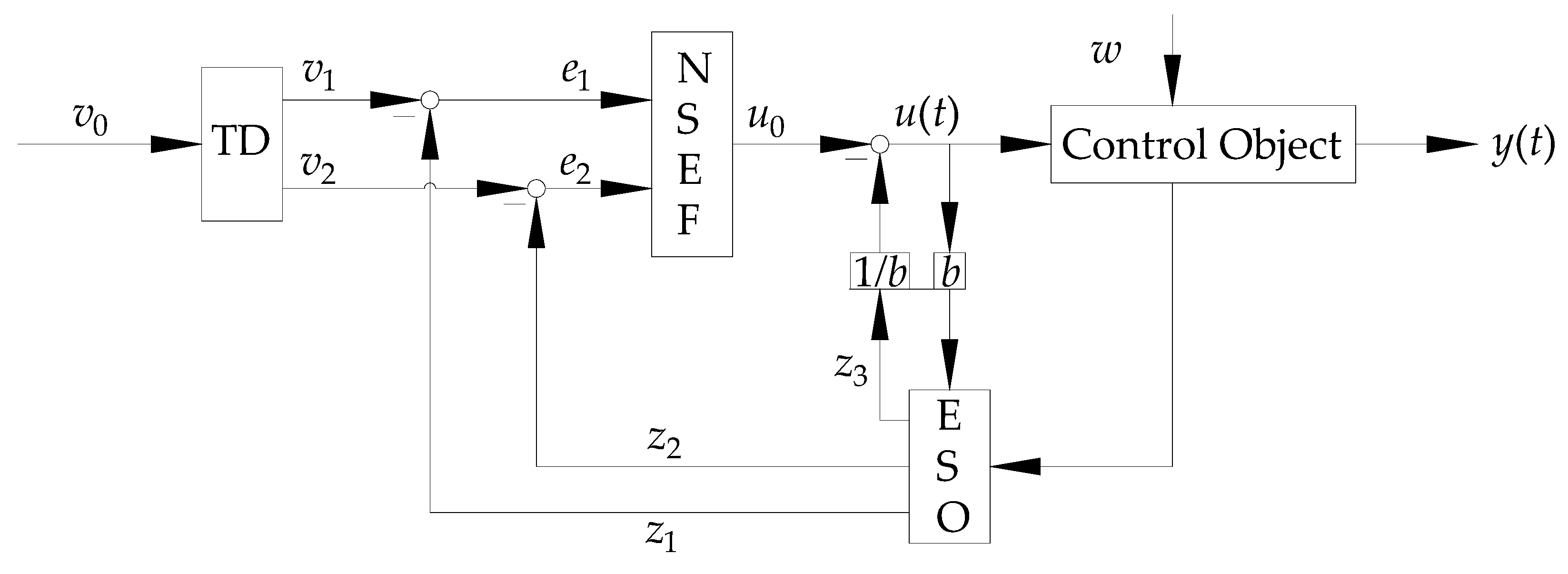
The ADRC consists of three parts: A tracking differentiator (TD), an extended state observer (ESO), and nonlinear state error feedback (NSEF). The core of the ADRC is an expansion controller. The linear ACRC (LADRC) also involves three parts: A TD, a linear ESO (LESO), and linear state error feedback (LSEF). The TD is applied to arrange the transition process, and the expansion state controller is applied to estimate the system state, model, and external disturbance. This means the information about state feedback and model and external disturbance compensation are extracted to use the expansion controller. The model and external disturbance of the system are located at the same position, which gets compensation through the estimation of real-time action by the expansion controller. The expansion controller is applied to get integral series by nonlinear state feedback from nonlinear uncertain objects with unknown external disturbances. It is a structure that also implements feedback linearization for nonlinear uncertain objects. Moreover, this feedback linearization of the ADRC relies on the dynamic estimation of the state observer rather than the precise mathematical model of the object. The state error feedback is not necessarily limited to the linear form, and the more appropriate nonlinear configuration should be used, then it produces the NSEF control law.
3.2. Design of ADRC for This Research
A second-order ADRC is taken as an example to design a temperature control system, whose structure is shown in
Figure 2.
For the proposed temperature control system, the input signal is v0, the control quantity of the system is u(t), the output of the system is y(t), and the external disturbance is w. The algorithms of the ADRC are shown as Equations (1)–(13).
is the tracking signal at time k + 1;
is the tracking signal at time k;
is the simulation step;
is the differential signal of at time k;
is the differential signal of at time k + 1;
is the fastest controlled synthesis function;
is the input signal;
is the speed factor; and
is the filtering factor.
is the input signal at time k;
is an adjustable parameter;
is a linear saturation function;
and are interval length;
is the tracking signal (error signal) at time k;
is the output of the system at time k;
is the independent variable; and
is the symbolic function.
is the error;
is the estimation of the output at time k;
is the estimation of the output at time k + 1;
is the estimation of the differential of the output at time k;
is the estimation of the differential of the output at time k + 1;
is the estimation of total disturbance of the system at time k;
is the estimation of total disturbance of the system at time k + 1;
,, are the parameters of the observer;
is a nonlinear function;
is the adjustable parameter from 0 to 1;
is a special parameter;
is the adjustable parameter from 0 to 1; and
is the control amount of the system at time k.
is the estimated error between ranged transition process and system output;
is the differential of errors between ranged transition process and system output;
is the control component;
is the proportional gain;
is the differential gain;
is the adjustable parameter from 0 to 1; and
is the error.
Parameter adjustment of nonlinear TD: When the ADRC has an effect in a closed-loop system, the TD simply gives a differential signal to the input signal and the tracking signal adjusts the parameters r, h, h0 in the open-loop system.
Parameter adjustment of ESO: The three parameters k1, k2, k3 of the extended state observer have a great influence on the closed-loop system. When the system has a large inertia coefficient and a long-time lag, the parameters k1, k2, k3 get larger. When the system overshoots too much, the overshoot can be suppressed by appropriately decreasing k3.
Parameter adjustment of NSEF: The parameters have an explicit physical meaning. The parameter β01 represents the proportional gain. The parameter β02 represents the differential gain, and the parameter tuning can use the proportion (P) and differentiation (D) setting theory in the PD controller. The function of NSEF generates a nonlinear control law. When the control speed is fast, the control purpose is achieved by decreasing β01, otherwise β01 will increase. Acceleration of the adjustment speed may increase the overshoot, which can be suppressed by increasing β02 to get smaller oscillations.
The ADRC also has a special parameter b, which is related to the control quantity u and the state quantity z3 of the state observer. The selection of different b is equivalent to changing the total disturbance value in different ranges, and the compensation component can also be changed in response. The selection principle of b is that a larger b can effectively compensate the disturbance and uncertainty of the model when the delay time of the object is longer.
According to the calculation and analysis of the ADRC, the proposed solar dedicated ventilation system can be controlled within a precise range.
3.3. Control Logic of the Proposed Solar Dedicated Ventilation System Based on ADRC
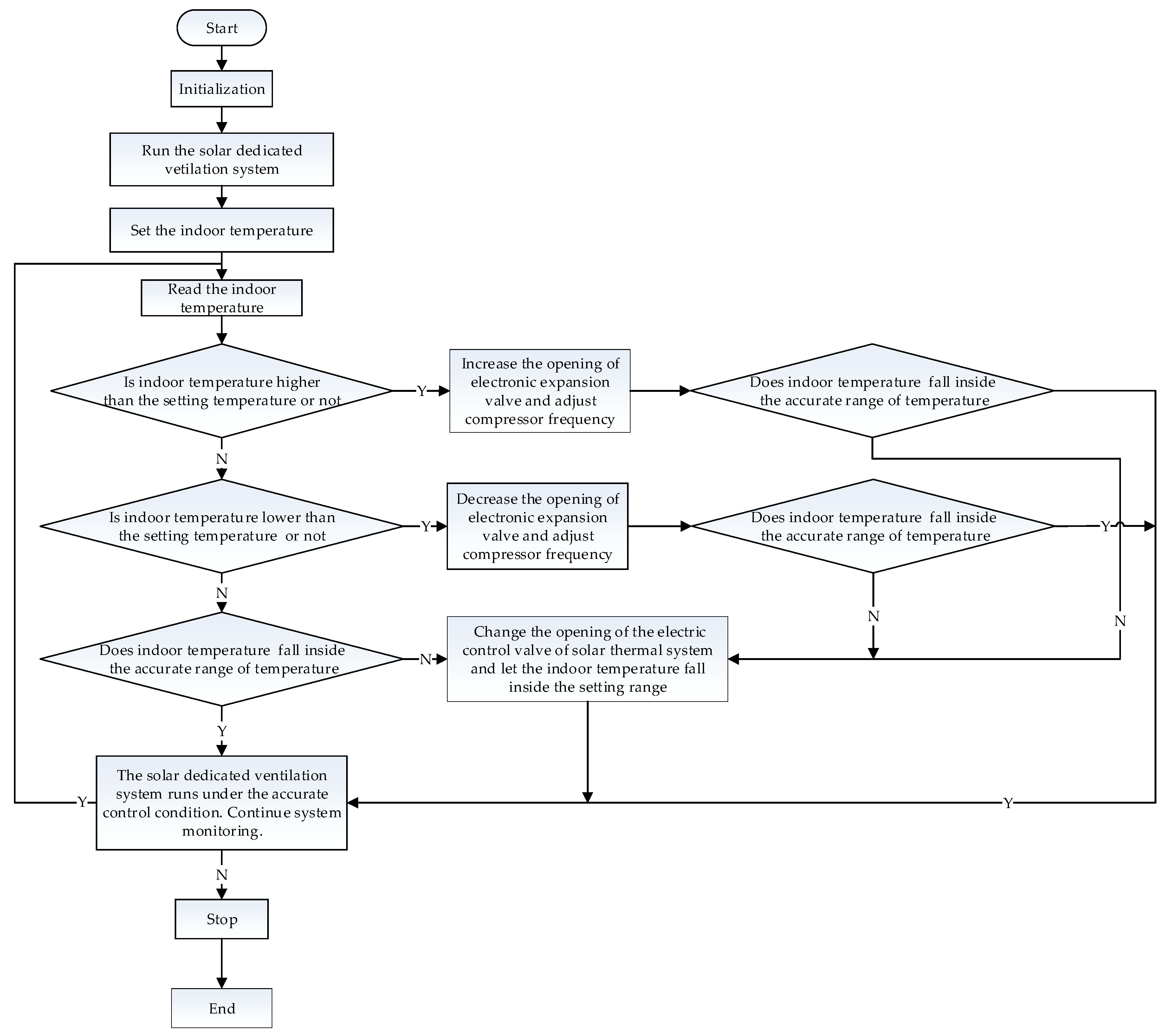
The control logic of the proposed solar dedicated ventilation system is necessary to realize accurate control. The logic controls the indoor temperature by using the ADRC to adjust the opening of the electric control valve of the solar thermal system, the opening of the electronic expansion valve of the dedicated ventilation system, and the compressor frequency. The regulating process involves primary and secondary regulation for accurate control. The control strategy regulates the opening of the electronic expansion valve and the frequency of the compressor in the primary adjustment and the opening of the electric control valve of the solar thermal system in the secondary adjustment based on the indoor conditions. If the indoor temperature is higher than the setting temperature, the ADRC can be applied to increase the opening of the electronic expansion valve and adjust the compressor frequency to meet the indoor temperature requirement. The ADRC can also change the opening of the electric control valve of the solar thermal system to achieve accurate control. Similarly, if the indoor temperature is lower than the setting temperature, the ADRC can be applied to decrease the opening of the electronic expansion valve and adjust compressor frequency, and then change the opening of the electric control valve of the solar thermal system. The temperature setting range is an accurate scope. When the indoor temperature does not fall inside the accurate temperature range, the ADRC will adjust the proposed system to the proper temperature range.
Besides, a delay must be set for the indoor temperature change and regulating process on the flow process chart (for example, regulating the opening of the electric control valve of the solar thermal system and of the electronic expansion valve and compressor frequency of dedicated ventilation system by ADRC). A flowchart of the control system is shown in
Figure 3.
Consequently, stability and accuracy can be obtained by this proposed precision control system.
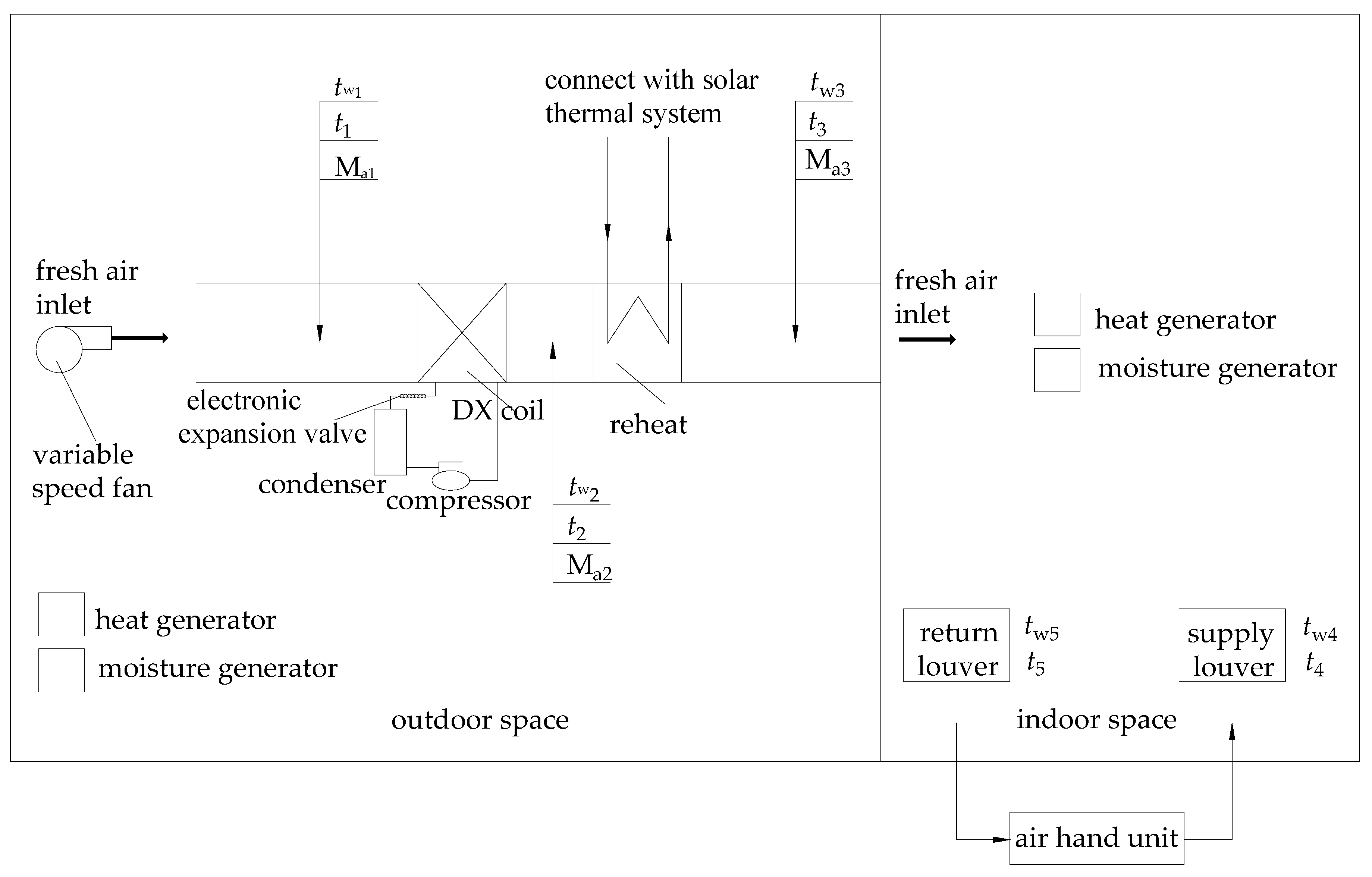
4. Experimental System
The experimental system, shown in
Figure 4, was designed to calculate and analyze the energy-saving features of the proposed solar dedicated ventilation system. This experimental system involves a variable speed fan, a heat insulation duct, a reheating system that can get thermal energy from the solar thermal system, and a DX coil with its cooling and dehumidification system, which has an electronic expansion valve, condenser, and inverter compressor. This cooling and dehumidification system is driven by 1.5 kW electrical power. The variable speed fan is located at the inlet side of the duct to control the air flow rate. All the equipment gets its electrical power supply from the photovoltaic system. The cooling output is controlled by the setting conditions of the indoor chamber by adjusting the electric control valve of the solar thermal system, the electronic expansion valve, and the inverter compressor. This experimental system is an approximate adiabatic system to minimize heat loss. A series of thermal insulation materials is used for the ductwork and experimental equipment.
There are two nearly adiabatic spaces in this test rig. One simulates the outdoor conditions and the other simulates indoor conditions, as shown in
Figure 4. Two sets of heat generators and moisture generators were applied to realize the variable space load conditions for both the indoor and outdoor conditions through sensible heat and latent heat changes. As the heat generator and moisture generator run by themselves, the sensible heat ratio (SHR) can be adjusted to simulate a wider range of operating conditions. The air handling unit (AHU) was applied to supply a cooling load for this system to meet the thermal energy balance. The power of the heat generator is 0–10 kW and the power of the moisture generator is 0–5 kW, which are adjusted by the ADRC.
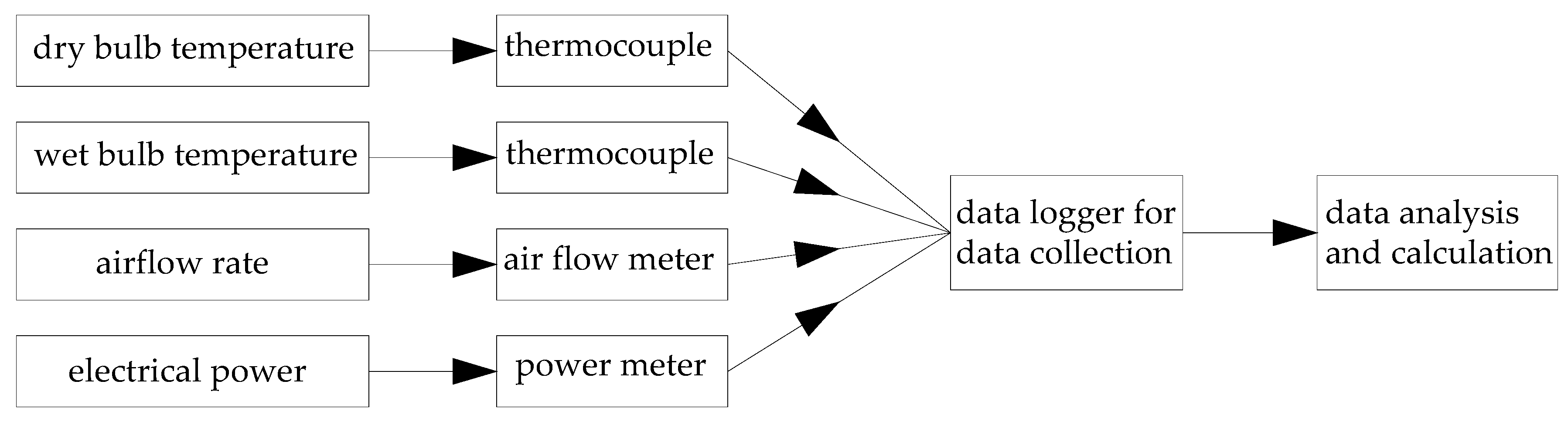
Test instruments were used in this experiment. The wet-bulb and dry-bulb temperatures were measured by using thermocouples and the airflow rate was measured by an air flow meter. Moreover, all the equipment was connected with the power meter to measure how much electrical power is supplied by the photovoltaic system. The major instruments are thermocouples, which measure the wet-bulb and dry-bulb temperatures within a range from –50 to 100 °C with an accuracy of ± (0.05% rdg + 0.5 °C); an air flow meter, which measures the airflow rate within a range from 0 to 10 m
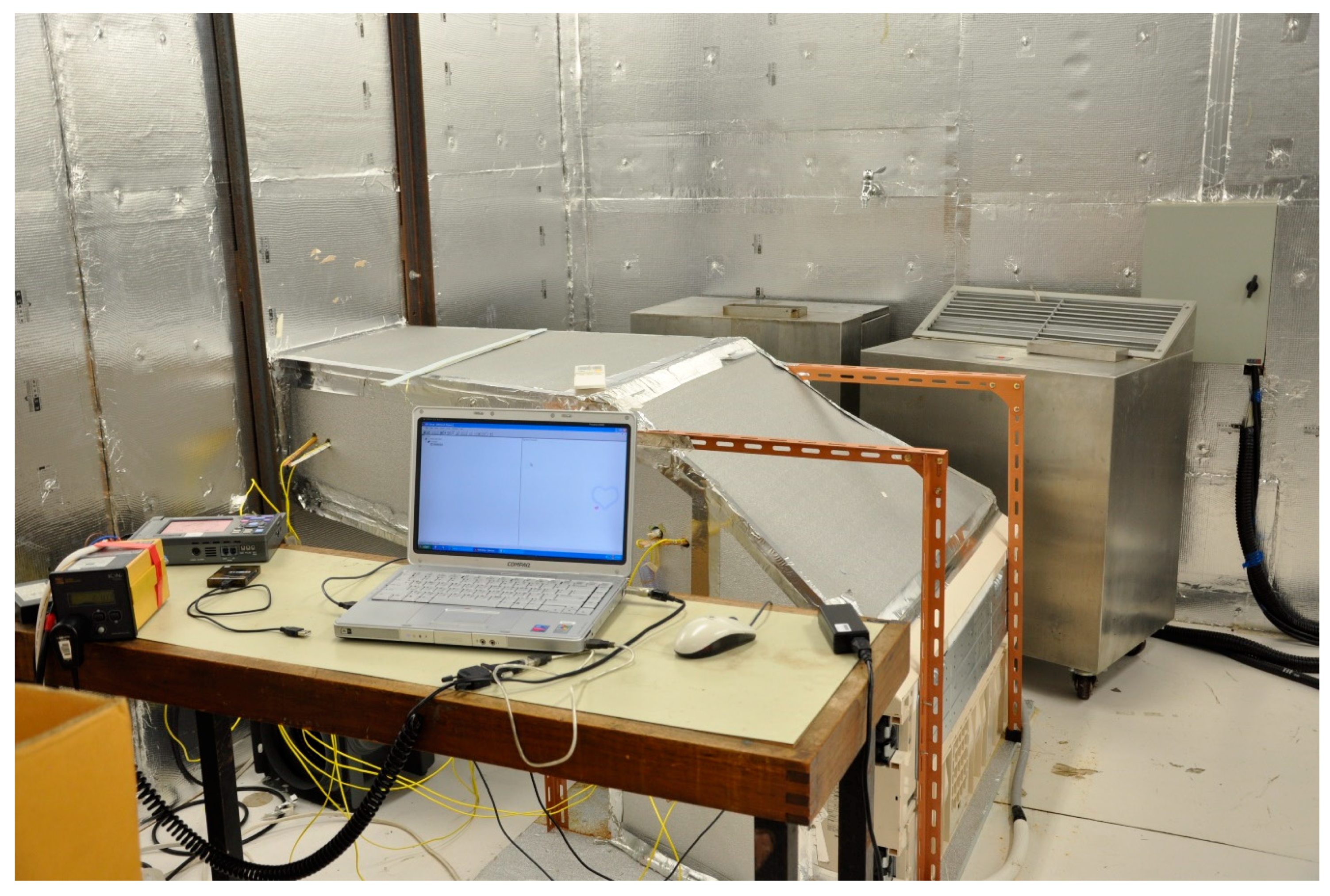
3/s with an accuracy of ±1%; and a power meter, which measures all the electrical power within a range from 0 to 60 A. The data loggers connect with all the meters to save the experimental data. The system should maintain a thermal energy balance state all the time. A schematic figure of data collection is shown in
Figure 5 and the photo of experimental environment is shown in
Figure 6 respectively.
As climatic conditions in this paper refer to summer in most parts of China and subtropical areas in southern China, the common dry-bulb temperature almost falls in the range 20 to 35 °C and relative humidity almost falls in the range 35% to 90%. It is necessary to keep the dry-bulb temperature and relative humidity values appropriate for the hot and humid conditions to gain the relevant accurate data in these experiments. Therefore, the test process should satisfy the indoor (setting conditions: 22 °C and 50%) and outdoor (range: 25 to 35 °C at 5 °C interval for temperature, 50% to 80% at 10% interval for relative humidity, and 0.1 to 0.3 m3/s at 0.05 m3/s interval for airflow rate) thermal conditions, which are similar to the actual environments in these experiments. The data were collected after the experimental system reaches steady-state equilibrium, which takes more than a half-hour for each experiment. All the data were saved once a minute, and average values were taken within a half-hour as the final experimental data for analysis.
This experimental system obtained average values of each test point for calculation and analysis and maintained a thermal energy balance state during the entire experimental time.
The thermal energy balance equation is:
where
is cooling load supplied by the hand unit at time j (kW);
is cooling load of fresh air at time j (kW);
is cooling load provided by the DX at time j (kW);
is heating load from the solar thermal system j (kW); and
j is time (min).
For the outdoor chamber, the cooling load of the fresh air and DX, the heating output from the solar thermal system, and the power output of the heat generator and moisture generator were controlled by the ADRC. For the indoor chamber, the cooling output from the air hand unit and the power output of the heat generator and moisture generator were also controlled by the ADRC. The latent and sensible loads were changed by the wet-bulb and dry-bulb temperatures. All the electrical power of this experimental system was supplied by the photovoltaic system.
It must comply with the following two equations for accurate control:
where
is the setting of the dry-bulb temperature of the indoor space (°C);
is the setting of the wet-bulb temperature of the indoor space (°C);
is the wet-bulb temperature of test point 2 at time j (°C); and
is the dry-bulb temperature of test point 2 at time j (°C).
5. Results and Discussion
The proposed solar dedicated ventilation system was tested by the experimental system to compare with the conventional system and heat pipe heat exchanger combined with dedicated ventilation (the former study). The accurate control and energy-saving potential of the proposed system will be analyzed and discussed in this part.
5.1. Accurate Control
According to
Section 4, the experimental system has some outdoor conditions, which are temperature (25 °C, 30 °C, 35 °C), relative humidity (50%, 60%, 70%, 80%), and airflow rate (0.1 m
3/s, 0.15 m
3/s, 0.2 m
3/s, 0.25 m
3/s, 0.3 m
3/s), and one indoor condition (22 °C and 50%). Therefore, there are 60 outdoor conditions (temperature × relative humidity × airflow rate = 3 × 4 × 5) in this experiment. Three representative outdoor conditions (25 °C, 50%, 0.1 m
3/s; 35 °C, 80%, 0.3 m
3/s; and 30 °C, 60%, 0.2 m
3/s) were chosen from the 60 outdoor conditions for the analysis.
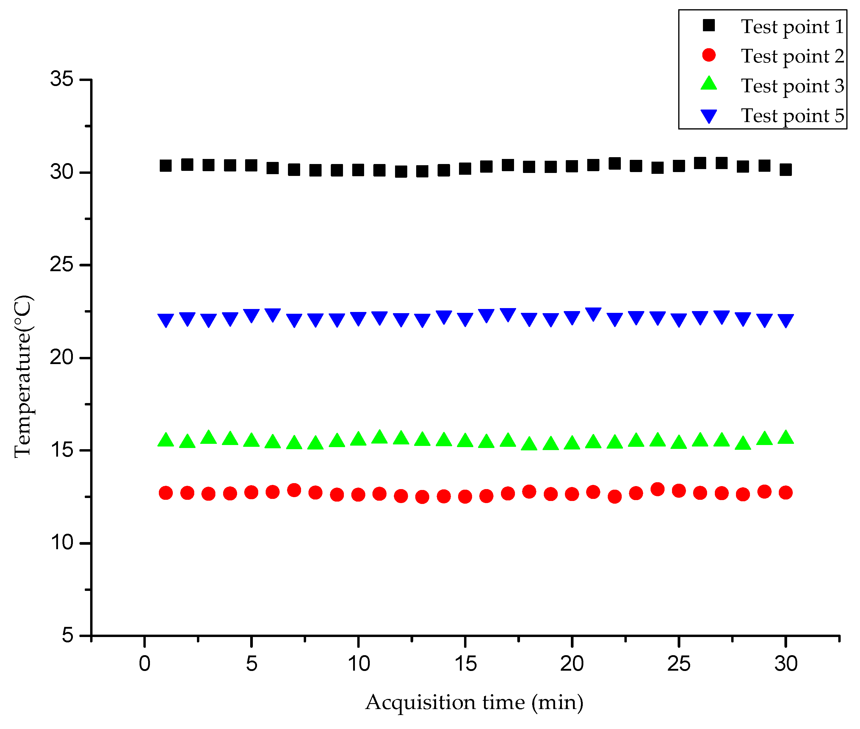
The temperature of four test points has a smaller fluctuation range at different outdoor conditions, which are shown in
Table 1,
Table 2 and
Table 3 and
Figure 7,
Figure 8 and
Figure 9. The maximum and minimum temperature standard deviations are 0.15 and 0.09 °C, respectively, at different outdoor conditions. The temperature difference between maximum and minimum is from 0.33 to 0.49 °C (<0.5 °C) at different outdoor conditions. This means the proposed solar dedicated ventilation system based on ADRC has high control accuracy.
The standard deviation and temperature difference between maximum and minimum are the lowest at 25 °C, 50%, 0.1 m
3/s, as shown in
Table 1. The highest value of standard deviation and temperature difference between maximum and minimum are 35 °C, 80%, 0.3 m
3/s, as shown in
Table 2. The results show that various outdoor conditions (temperature (T), relative humidity (RH), and airflow rate) influence the control accuracy of the proposed solar dedicated ventilation system. For different outdoor conditions (T, RH, and airflow rate), standard deviation and temperature difference between maximum and minimum have the same trend, increasing with an increase of outdoor conditions. These results also indicate that higher outdoor conditions (T, RH, and airflow rate) lead to lower control accuracy.
The outdoor conditions of this experiment cover most subtropical climates and summer environments. The temperature difference between maximum and minimum of the worst outdoor environment (35 °C, 80%, 0.3 m3/s) is between 0.49 and 0.47 °C and the optimal outdoor condition (25 °C, 50%, 0.1 m3/s) is between 0.42 and 0.33 °C, which means the ADRC can control the proposed system within a good precision range.
Test point 3 is the supply air point of the proposed system. The temperature standard deviation is from 0.09 to 0.13 °C, which ensures that the indoor temperature (test point 5) is controlled within an accurate range (standard deviation is from 0.09 to 0.11 °C) by using the ADRC.
The average temperature difference between test point 2 and test point 3 is 2.29 °C (25°C, 50%, 0.1 m3/s), between test point 2 and test point 3 is 2.87 °C (35 °C, 80%, 0.3 m3/s), and between test point 2 and test point 3 is 2.78 °C (30 °C, 60%, 0.2 m3/s).
These results demonstrate that the proposed solar dedicated ventilation system can supply fresh air to the indoor chamber through a lower temperature difference compared with the conventional system to enhance the indoor thermal comfort.
5.2. Energy-Saving Potential
Fresh air is cooled and dehumidified only by direct expansion before providing it to the indoor space in the conventional system. The cooling load of fresh air can be expressed as:
where
is the cooling load of fresh air at time j for the conventional system (kW);
is air density (kg/m3);
is the airflow rate of fresh air (m3/s);
is air enthalpy of test point 2 at time j for the conventional system (kJ/kg); and
is air enthalpy of the indoor space (kJ/kg).
Fresh air was cooled and dehumidified by the heat pipe heat exchanger combined with the dedicated ventilation system before being provided to the indoor space in the former study [
14]. The cooling load of fresh air can be expressed as:
where
Fresh air is cooled and dehumidified by the proposed solar dedicated ventilation system before being provided to the indoor space in this study. The cooling load of fresh air can be expressed as:
where
,
, and
are tested and saved for calculation and analysis in the experimental system automatically.
can be calculated by the thermal energy balance Equation (14). As the power of
,
, and
is supplied by the photovoltaic and solar thermal system, the power of
is also supplied by solar energy in the proposed system compared with the former system. The proposed system will only use solar energy, not including extreme conditions. Extreme situations that need a standby power supply for the proposed solar dedicated ventilation system rarely occur in southern China and in summer in most parts of China. Solar energy has replaced traditional energy, and the energy-saving potential of the proposed system equals the power consumption of traditional systems, excluding extreme conditions. Therefore, it can be concluded that the proposed solar dedicated ventilation system could gain the most energy-saving potential compared with the conventional and previous systems [
12,
13,
14].
However, there are some shortcomings of the proposed system. In the first place, the proposed system is affected by weather conditions and geographical location and its efficiency is quite different in different regions. In the second place, an adequate energy storage system is significant for the proposed system. Finally, the initial investment for the proposed system is larger and the payback period is longer than for the former systems. Therefore, the actual operation of the proposed solar dedicated ventilation system will be evaluated in the next section.
6. Evaluation of Actual System
The proposed solar dedicated ventilation system has been used in actual operation as the cooling system of a laboratory (the previous study was conducted for a laboratory), and the evaluation will be shown in this part. A lot of calculations and analyses for the operation of the proposed system were conducted, and the energy-saving potential, initial investment, and payback period are compared with the former systems in this paper.
The cooling area of this laboratory is nearly 300 m2. One year’s operation of the laboratory has been recorded and the data have been collected. For 8760 h of one year’s operation, about 2752 h of cooling system use is needed under outdoor and indoor conditions, which is proposed in the experimental part of this paper. There are almost no extreme cases in the 2752 cooling hours.
a. Comparison between the proposed solar dedicated ventilation system and the conventional system
The electrical energy per unit area of the actual laboratory system supplied by the proposed system is 58.43 W/m2. This indicates the energy-saving potential of the proposed system relative to the conventional system based on the operation data and calculations. Standard coal consumption and CO2 emissions could be reduced by 64.31 kg/m2 and 160.32 kg/m2, respectively, according to the energy-saving potential compared with the traditional system.
b. Comparison between the proposed solar dedicated ventilation system and heat pipe heat exchanger combined with dedicated ventilation system
The energy-saving potential of the heat pipe heat exchanger combined with a dedicated ventilation system compared to the conventional system was proposed in previous research [
14]. Compared with the heat pipe heat exchanger combined with a dedicated ventilation system, the energy-saving potential of the proposed system is 55.8 W/m
2. The corresponding reduction of standard coal consumption and CO
2 emissions is 61.42 kg/m
2 and 153.11 kg/m
2, respectively.
Three different systems (conventional system, heat pipe heat exchanger combined with dedicated ventilation system, and the proposed solar dedicated ventilation system) were compared from different aspects under the same conditions in this laboratory. The results are shown in
Table 4.
It can be seen in
Table 4 that the proposed solar dedicated ventilation system will provide benefit by the sixth year, leaving 19 years of net income according to a 25-year system life.
7. Conclusions
A photovoltaic and solar thermal system combined with a dedicated ventilation system was proposed in this paper. These three systems were combined to realize energy conversion, management, and energy-saving compared with former systems. The photovoltaic system supplies all the electrical power and the solar thermal system supplies all the thermal energy to the proposed solar dedicated ventilation system. The dedicated ventilation system processes fresh air and return air and supplies it to the indoor chamber to meet the sensible load and latent load requirements. An ADRC was designed to realize intelligent and precise control and was used for the experimental system.
In order to evaluate the control accuracy and calculate the energy-saving potential of the proposed system when it is used in the summer in most of China or southern China, an experimental system was installed and tested to assess its characteristics under different outdoor and indoor conditions. The results were used for a comparison between the proposed system and former systems, which are a conventional system and a heat pipe heat exchanger combined with a dedicated ventilation system. Moreover, they were applied to confirm that the proposed solar dedicated ventilation system has maximum energy-saving potential compared to the previous systems.
The experimental results show that the temperature standard deviation is from 0.09 to 0.15 °C at different outdoor conditions. This means the proposed system based on ADRC has high control accuracy. The temperature difference between maximum and minimum is from 0.33 to 0.49 °C (<0.5 °C) at different outdoor conditions. Standard deviation and temperature difference between maximum and minimum are the lowest at 25 °C, 50%, 0.1 m3/s and the highest at 35 °C, 80%, 0.3 m3/s. The results show that the various outdoor conditions (T, RH, and airflow rate) influence the control accuracy of the proposed solar dedicated ventilation system. The results also indicate that solar energy has replaced traditional energy and the energy-saving potential of the proposed system equals the power consumption of traditional systems, excluding extreme conditions.
Furthermore, the actual operating cooling system for a laboratory was evaluated and the performance was compared with the former systems. The energy-saving potential could reach 58.43 W/m2 and standard coal consumption and CO2 emissions could be reduced by 64.31 and 160.32 kg/m2 compared with the conventional system. The payback period of the proposed system is 5.32 years. Nevertheless, there are some shortcomings, which are higher initial investment and longer payback period for the proposed system.
Finally, the proposed solar dedicated ventilation system based on ADRC, which has the most energy-saving potential and control accuracy, could be used for areas with abundant solar energy resources to achieve economic and environmental benefits.


