Article

Simultaneous Measurement Method and Error Analysis of the Six Degrees-of-Freedom Motion Errors of a Rotary Axis

MoE Key Laboratory of Luminescence and Optical Information, Beijing Jiaotong University, Beijing 100044, China
*
Author to whom correspondence should be addressed.
Appl. Sci. 2018, 8(11), 2232; https://doi.org/10.3390/app8112232
Submission received: 28 September 2018 / Revised: 31 October 2018 / Accepted: 7 November 2018 / Published: 13 November 2018
(This article belongs to the Special Issue Precision Dimensional Measurements)

Abstract

:
Error measurement of a rotary axis is the key to error compensation and to improving motion accuracy. However, only a few instruments can measure all the motion errors of a rotary axis. In this paper, a device based on laser collimation and laser interferometry was introduced for simultaneous measurement of all six degrees-of-freedom motion errors of a rotary axis. Synchronous rotation of the target and reference rotary axes was achieved by developing a proportional–integral–derivative algorithm. An error model for the measuring device was established using a homogeneous transformation matrix. The influences of installation errors, manufacturing errors, and error crosstalk were studied in detail, and compensation methods for them were proposed. After compensation, the repeatability of axial and radial motion errors was significantly improved. The repeatability values of angular positioning error and of tilt motion error around the y axis and x axis were 28.0″, 2.8″, and 3.9″. The repeatability values of translational motion errors were less than 2.8 μm. The comparison experiments show that the comparison errors of angular positioning error and tilt motion error around the y axis were 2.3″ and 2.9″, respectively. These results demonstrate the effectiveness of our method and the error compensation model.

1. Introduction

Rotary axes are widely applied in computer numerical control machining, robotics, aerospace, and other fields. Rotary axes with inadequate motion accuracy directly reduce the working accuracy of the related precision machines. The first and most important step to increase the accuracy of the axes and decrease the influence of the errors is to quickly and accurately measure the motion errors of the rotary axes.
A complete description of the motion errors of a rotary axis requires six physical quantities [1]: the angular positioning error (ECC), the tilt motion error around the y axis (EBC), the tilt motion error around the x axis (EAC), the radial motion error along the x axis (EXC), the radial motion error along the y axis (EYC), and the axial motion error (EZC). In order to make the symbols convenient for the subsequent calculation of the coordinate transformation, we use the simpler symbols εz, εy, εx, δx, δy, and δz instead of ECC, EBC, EAC, EXC, EYC, and EZC in the calculation. The real motion trajectory of the axis can be reconstructed using these six motion errors, and the application precision of the related mechanical equipment can be improved by compensating for the errors. Therefore, the key problem to be solved is how to obtain the six degrees-of-freedom (DOF) motion errors of the axis with high precision and high efficiency. At present, the simultaneous measurement methods of multi-DOF motion errors are mainly based on laser properties [2,3,4], material profile [5], trajectory analysis [6], and other factors [7].
Chen’s apparatus, using three lasers, is a rare method that can measure the six DOF motion errors of a rotary axis simultaneously and directly [8]. While its structure is complicated, H. Schwenke used the laser tracker [9] to study the measurement of the six DOF errors. Ibaraki used the R-test [10,11] method to identify the six errors. However, most of these indirect measurement methods need to determine each error using complex function-fitting algorithms. Unlike these existing methods, our method can measure the six DOF errors directly at the same time. It also has the advantages of easy installation and high measurement efficiency. Two important methods—a servo-tracking strategy and error model analysis—are used to realize and improve the functions of the measuring device.
In this paper, a device for the simultaneous measurement of the six DOF errors of a rotary axis is introduced, and a method to improve the measurement accuracy is proposed based on our previous research for five DOF errors [2,12]. The automatic measurement is achieved by using the servo-tracking strategy. It is also used to overcome the difficulty of the beam needing to be uninterrupted during the interferometric process. A complete model for measuring all six DOF motion errors is proposed. The factors influencing the measurement result are analyzed, and a compensation method is proposed. In Section 2, the measurement principle of our device is briefly introduced. The servo-tracking strategy of the reference rotary axis is described in detail. An error model is established using the homogeneous transformation matrix (HTM) [13,14]. In Section 3, we describe a series of experiments, which were carried out to simultaneously measure the six DOF errors of a rotary axis. The repeatability and comparison results were obtained after compensation and demonstrate the effectiveness of our method and the error compensation model.

2. Principle and Model

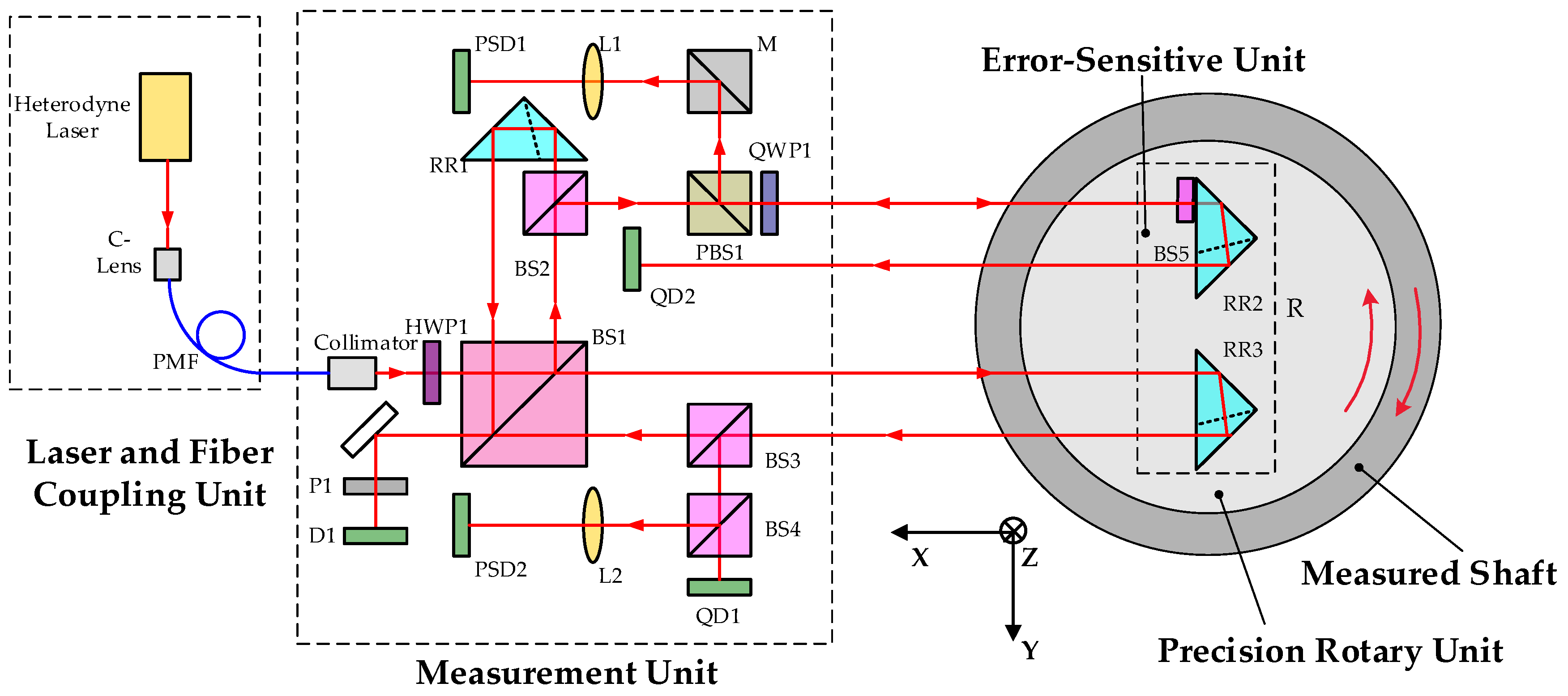
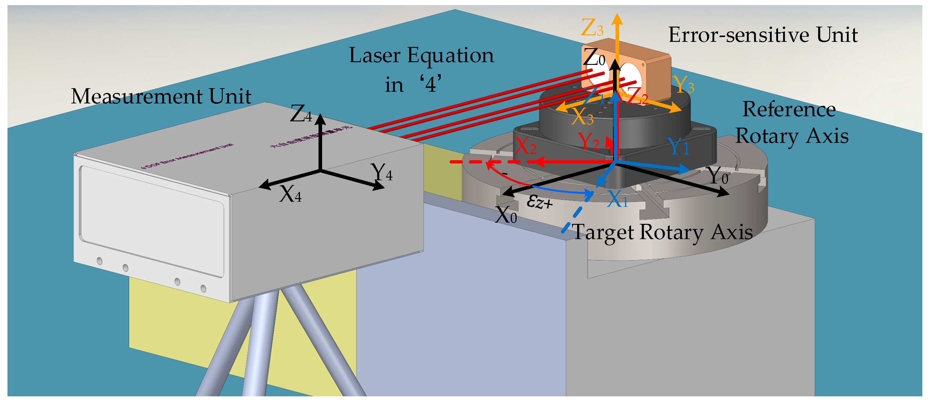
2.1. Measurement Principle

The measuring device includes a laser and fiber coupling unit, a measurement unit, an error-sensitive unit, and a reference rotary unit [2]. The measurement unit and the error-sensitive unit constitute the main optical path. The optical path is divided into a collimation measurement part and an interferometry measurement part. The collimation measurement part consists of two quadrant detectors (QDs) and two position-sensitive detectors (PSDs). As shown in Figure 1, QD1 receives the light reflected back from a retro-reflector (RR3) to detect the radial motion error along the y axis and the axial motion error of the target rotary axis. QD2 is similar to QD1, and the difference between the two QDs in the vertical direction corresponds to the tilt motion error around the x axis. PSD1 receives the light reflected from a mirror (a beam-splitting film, BS3) and detects the angular error around the z axis and tilt motion error around the y axis. The target rotary axis rotates a nominal angle (θnominal), and the reference rotary axis rotates in the opposite direction (θencode). The angular positioning error is determined by YPSD1 (the y direction of PSD1), θencode, and θnominal. PSD2 detects the laser beam drift [2]. The interference part consists of the reflected light by RR1 (as the reference light) and the reflected light by RR3 (as the signal light). Detector D1 records the changes in the interference signals, which correspond to the radial motion error along the x axis. Combined with collimation and interferometry, the measuring device is capable of the simultaneous measurement of all six of the DOF motion errors of a rotary axis.
To ensure the continuity of the interference signal, the reference rotary axis needs to rotate synchronously with the target rotary axis. The proportional–integral–derivative (PID) algorithm was developed to achieve the servo-tracking strategy, and this process is shown in Figure 2. The start and end thresholds are based on the horizontal data of QD1. After the target rotary axis starts to rotate, the light incident to QD1 will deviate from its initial position. When the light reaches the start threshold, the reference rotary axis starts to rotate in the opposite direction. According to the data in the horizontal direction of QD1, the PID algorithm continuously outputs the speed commands to the reference axis. By constantly adjusting the speed, the reference axis rotates at a relatively stable speed with the target axis. When approaching the measuring position, the target axis rapidly decelerates to a stop. When the QD data reaches the end threshold, the computer stops the reference axis, and the servo-tracking process is completed. In order to eliminate errors introduced by bi-directional rotation, the reference axis is set to rotate in only one direction. Thus, if the speed calculated using PID is negative, the speed command will be zero.
In order to shorten the control delay of the host computer, separate threads for the data acquisition from the detectors and PID algorithm were opened. By changing the end threshold, the stop position of the spot on QD1 is controlled; thus, the linear range of the QD detector can be fully utilized. The proportion coefficient of PID determines the stable state of the motion. An excessively small proportion coefficient will cause interference signal interruption, while an excessively large proportion coefficient will cause unstable movement of the reference axis, which is not suitable for measurement. The differential coefficient is sensitive to a sudden change. Thus, it can cope with excessive acceleration when the target axis starts or stops. Through the servo-tracking strategy, the device not only realizes interferometry but also reduces the time of a full-circle measurement from about 30 min [12] to less than 15 min.

2.2. Error Model Establishment and Analysis

Various errors will be inevitably introduced in the measurement process. The data from the detectors (QD1, QD2, PSD1, PSD2, and D1) are affected by the six DOF motion errors, installation errors, manufacturing errors, etc. An error model was established to improve the accuracy of our measuring device. The error sources and influences on the measurement results were analyzed using the model, and the corresponding compensation methods were studied.
The model was established in a three-dimensional space. The measuring device mainly includes the target rotary axis A, the reference rotary axis B, the error-sensitive unit C, and the measurement unit. The coordinate systems “1” to “4”, fixed to the corresponding parts and moving with them, were established, respectively, as shown in Figure 3. The world coordinate system “0” was established, and the initial state of coordinate system, “1”, coincides with the coordinate system “0”. The HTM T n m between the adjacent coordinate systems was established. This matrix can be used to simulate the motion of rotary axes and to realize the coordinate transformation [12]. T n m represents the transformation matrix from the coordinate system m to the coordinate system n. We assume that the coordinate system “1” is obtained after a series of motions of the coordinate system “0”. The order of the motions is as follows: first translate δx, δy, and δz; then rotate εx, εy, and (θ + εz). This process defines the six DOF errors. The coefficient matrix LC4 of the output beam equation is defined in the coordinate system “4”, and the reflection matrix R is defined in the coordinate system “3” [12]. According to Equation (1), the coefficient matrix LoutC4 of the reflected light can be calculated using the HTMs and the reflection matrix. Based on the structure of the measuring device and the ray tracing principle, the expressions of the six DOF motion errors of the rotary axis can be obtained.
L o u t C 4 = L C 4 T 4 0 T 0 1 T 1 2 T 2 3 R T 3 2 T 2 1 T 1 0 T 0 4
In the error model, angular errors are generally expressed in ε, and translational errors are expressed in δ. Different subscripts are used as a distinction. The specific variables and their naming rules are shown in Table 1.
The data in the horizontal and vertical directions of the detectors are represented by Y and Z, respectively. PSDs and QDs are distinguished by the subscript. For example, YPSD1 is the data in the horizontal direction of PSD1. (θ = 0) is added, which represents the initial value of the measurement. For example, YPSD1 (θ = 0) is the initial value in the vertical direction of PSD1. The naming of other parameters, such as structural parameters and optical parameters of the measuring device, is shown in Table 2.
According to the principle of laser collimation, all the DOF motion errors can be obtained—except for the radial motion error along the x axis—with the two types of photoelectric detectors [12].
The angular positioning error is calculated using the formula:
ε z = ( Y PSD 1 ( θ = 0 ) Y PSD 1 ) / 2 f + θ encode θ nominal ,
where YPSD1(θ = 0) = −f(−2εzca + 2εzL).
The tilt motion error around the y axis is calculated using the formula:
ε y = ( Z PSD 1 Z PSD 1 ( θ = 0 ) ) / 2 f ε x a b sin θ ε y a b cos θ + ε y a b ,
where ZPSD1(θ = 0) = −2f(εyca + εyabεyL).
The tilt motion error around the x axis is calculated using the formula:
ε x = ( Δ Δ ( θ = 0 ) ) / 2 D ε x a b cos θ + ε y a b sin θ + ε x a b ,
where Δ = ZQD1ZQD2 and
Δ ( θ = 0 ) = ( Z QD 1 Z QD 2 ) ( θ = 0 ) = 2 D ( ε x c a ε x a b + ε x L ) + ( n Q D C 1 x 4 + n Q D C 2 x 4 ) ε y c + ( D P 1 y + P 2 y ) ε x c .
According to Equation (2), the only influence on the angular positioning error is constant installation errors, which can be eliminated by subtracting the initial value in the first position of the rotary axis. As described in Equations (3) and (4), the two tilt motion errors are affected by the constant installation errors. The influence of the trigonometric form on the tilt motion errors is from the angle of the coaxiality deviation between the reference and target axes (εxab and εyab). This influence can be compensated for by function fitting. In addition, the manufacturing error (εxc and εyc) of the retro-reflector has a constant influence on the tilt error around the x axis, which can be eliminated by subtracting the initial value.
The radial motion error along the y axis can be calculated using the equation:
δ y = Y QD / 2 Y PSD O C 1 x / 2 n f Δ ( O C 1 z + H a ) / 2 D δ x a b sin θ δ y a b cos θ + δ y a b [ Y QD / 2 Y PSD O C 1 x / 2 n f Δ ( O C 1 z + H a ) / 2 D ] ( θ = 0 ) + [ ε z t ε z t ( θ = 0 ) ] ( O C x n + 2 P x + Q D C x ) + ( O C 1 z + H a ) 2 D ( Q D C 1 x + Q D C 2 x ) [ ε y t + ε y t ( θ = 0 ) ]
where
[ Y QD O C 1 x Y PSD / n f Δ ( O C 1 z + H a ) / D ] ( θ = 0 ) = 2 δ y c a + 2 ε z L P x 2 ε x L P z + 2 δ y a b   + 2 H a ε x c a + ( O C 1 z H a P z + P 1 z ) ε x c ε y c ( n Q D C 1 x 4 + n Q D C 2 x 4 ) ( O C 1 z + H a ) / D   + ( n P x O C 1 x + n   Q D C 1 x 4 ) ε z c ( D P 1 y + P 2 y ) ε x c ( O C 1 z + H a ) / D .
The axial motion error can be calculated using the equation:
δ z = Z QD / 2 O C 1 x Z PSD / 2 n f + O C 1 y Δ / 2 D [ Z QD / 2 O C 1 x Z PSD / 2 n f + O C 1 y Δ / 2 D ] ( θ = 0 ) ε y t ε y t ( θ = 0 ) 2 ( O C y D Q D C 1 x + O C y D Q D C 2 x Q D C x 2 P x + O C x n )
where
[ Z QD / 2 O C 1 x Z PSD / 2 n f + O C 1 y Δ / 2 D ] ( θ = 0 ) = 2 δ z c a + 2 δ z a b + 2 ε x L P y 2 ε y L P x + ( n P x n Q D C 1 x 4 + O C 1 x ) ε y c   + ( P y + O C 1 y P 1 y   ) ε x c   + ε y c ( n Q D C 1 x 4 + n Q D C 2 x 4 ) O C 1 y / D   + ( D P 1 y + P 2 y ) ε x c O C 1 y / D .
As described in Equations (5) and (6), the manufacturing errors and some of the installation errors have constant influences on the radial and axial motion errors. These influences can be eliminated by subtracting the initial value. The measurement result of the radial motion error along the y axis is affected by the offset of the coaxiality deviation of the two rotary axes. This effect—the trigonometric terms in equations—can be compensated for using function fitting. In Equation (5), YPSD/2f is related to the angular positioning error, and Δ/2D is related to the tilt motion error around the x axis. Thus, these two motion errors have influences on the measurement of the radial motion error along the y axis, which is the error crosstalk. Similarly, in Equation (6), two tilt motion errors have influences on the measurement of the axial motion error. All of the error crosstalk can be compensated for by the above model.
To measure the radial motion error along the x axis, the interference principle is used. Therefore, accurate analysis of the total optical path of the interference part is the key to describing the radial motion error along the x axis. The total optical path is divided into three parts: the optical path of the output light (Lo, yellow), the optical path in RR3 (Li, red), and the optical path of the reflected light (Lr, blue), as shown in Figure 4. According to the equations of the output and reflected light, the incident and emitted positions of the lights on the measurement unit or the retro-reflector can be obtained, and the total optical path of the interference can be calculated.
The optical path in RR3 is affected by the angular changes of the incident light, and the influences are second- and higher-order items, as shown in Equation (7). h is the height of the retro-reflector and i is the angle of incidence.
L i = 2 n h ( 1 sin 2 i / n 2 ) 1 / 2
The angular motion errors have larger influences on the optical paths of the output light and reflected light. The influences include the first-order items. After ignoring the second- and higher-order items, the optical paths of the output light Lo and the reflected light Lr are:
L o = B 3 + ( P y + P 1 y ) ( ε z c a ε z L + ε z ) ( H a P z P 1 z ) ( ε y c a ε y + ε y L ε y a b cos θ ε x a b sin θ ) L r = B 3 ( P y + P 1 y 2 O C y ) ( ε z c a ε z L + ε z ) ( P z + P 1 z H a 2 O C z ) ( ε y c a ε y + ε y L ε x a b sin θ ε y a b cos θ )
where
B 3 = δ xca + δ x + δ xab cos θ δ y a b sin θ + H a ( ε y a b cos θ + ε x a b sin θ + ε y ε y L ) P x P y ε z L + P z ε y L + L s
The total optical path can be expressed as:
L = L o + L i + L r = 2 ( δ x c a + δ x + δ x a b cos θ δ y a b sin θ ) + O C y Y PSD / f + ( H a + O C z ) Z PSD / f 2 ( P y ε z L + P z ε y L H a ε y c a ) 2 ( P x + L S n O C x ) + O C y ε z t ( H a + O C z ) ε y t .
Therefore, the radial motion error along the x axis is:
δ x = ( L L ( θ = 0 ) ) / 2 + O C y ( Y PSD Y PSD ( θ = 0 ) ) / 2 f + ( H a + O C z ) ( Z PSD Z PSD ( θ = 0 ) ) / 2 f ( δ x a b cos θ δ y a b sin θ δ x a b ) + O C y ( ε z t ε z t ( θ = 0 ) ) / 2 ( H a + O C z ) ( ε y t ε y t ( θ = 0 ) ) / 2 ,
where
L ( θ = 0 ) = 2 ( δ x c a + δ x a b ) + O C y Y PSD ( θ = 0 ) / f + ( H a + O C z ) Z PSD ( θ = 0 ) / f 2 ( P y ε z L + P z ε y L H a ε y c a ) 2 ( P x + L s n O C x ) + O C y ε z t ( θ = 0 ) ( H a + O C z ) ε y t ( θ = 0 ) .
Ls is the distance between the laser emission surface and the front surface of the measurement unit. The constant influence of some installation errors can be eliminated by subtracting the initial value in the first position of the rotary axis. The offset of the coaxiality deviation (δxab and δyab) has an influence on the measurement of the radial motion error. The trigonometric items can be compensated for by function fitting. In Equation (10), two angular motion errors also influence the measurement of the radial motion error. This kind of error crosstalk can be compensated for by using Equation (10).
The complete theoretical analysis shows that the measurement results of the six DOF motion errors are affected by several errors. The compensation methods are given in the above theoretical model, which can effectively compensate for error crosstalk, installation errors, and manufacturing errors and thus improve measurement accuracy.

3. Experiment Results

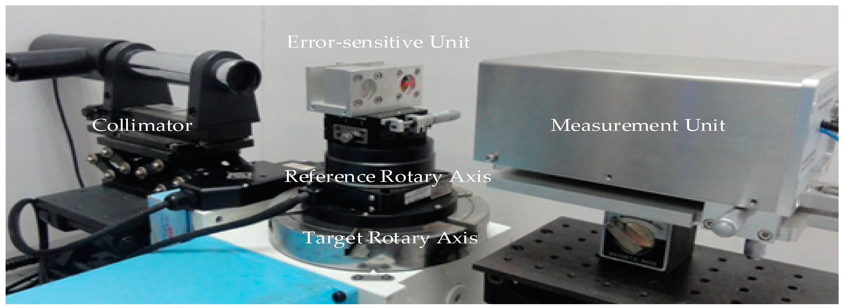
3.1. Experiment Conditions

Under laboratory conditions, the six DOF motion errors of a rotary axis were measured using our measuring device, as shown in Figure 5. The performance of the device was studied through experiments. The target rotary axis was the SKQ-12200 produced by KEOLEA. Its angular positioning error was 40″, and the repeatability value was 20″. The reference rotary axis was the ANT95-360-R produced by Aerotech. Its angular positioning error was 10″, and the unidirectional repeatability value was 0.5″. The repeatability value of the tilt motion errors was 3″; the repeatability values of the axial and radial motion errors were 0.5 and 1 μm, respectively. The measuring interval was 30°, and the rotation speed of the target rotary axis was about 0.55°/s. The experimental temperature was fixed at 25 ± 1 °C. The rotational velocity of the reference axis fluctuated around the velocity of the target rotary axis. The following errors were about 250″.

3.2. Repeatability Experiment

The full-circle measurement of the six DOF motion errors of the target axis was repeated nine times. At the same position, half of the fluctuation range of the nine measurements was defined as the repeatable value of this position. The maximum value of all the 13 positions was selected as the repeatability value of each motion error measured by the device.
The original data consist of various errors, and the real motion errors of the target axis can be obtained through error compensation. First, the initial values of the first position were subtracted from all the original data. Thus, the constant influence of errors, such as installation errors and manufacturing errors, could be eliminated. Then, the error crosstalk was compensated for according to the above equations. Finally, the installation errors due to the coaxiality deviations of the two axes were compensated for by function fitting. The final results of the repeatability experiment are shown in Figure 6.
The repeatability value of the angular positioning error was 28.0″. The repeatability values of tilt motion errors around the y axis and x axis were 2.8″ and 3.9″, respectively. The repeatability value of the radial motion error along the y axis was 2.8 μm. The repeatability value of axial motion error was 0.5 μm. The radial motion error along the x axis was 1.3 μm. As shown in Figure 6, the results at 0 and 360 degrees are not the same. There are mainly two reasons for this. One is that our device has repeatability values, which result in the noncoincidence of the measuring points. Our experimental results show that the maximum repeatability value of the angular motion error was 28.0″. The other is that the measured axis itself has a large repeatability value. The positions of 0 degrees and 360 degrees are the same in theory, but they are not in fact. Due to the characteristics of the measured axis, some motion errors of the measured axis near the 0 point vary greatly. Thus, even a small angular positioning error will lead to a large change in motion error.
The error model helps us not only obtain error data much closer to the real value but also compensate for the influence of error crosstalk on the repeatability measurement. As shown in Table 3, the repeatability values of translational motion errors were significantly improved by removing the fluctuations introduced by other angular motion errors.

3.3. Comparison Experiment

Restricted by the experimental conditions, only the angular positioning error and the tilt error around the y axis measured by our device were compared to the results measured by a standard instrument. An autocollimator AC300 (the standard instrument was produced by AcroBeam) measured the target axis simultaneously with the measuring device. The max error of the standard instrument is ±0.05″ in the range of ±300″ and the uncertainty of indication error is 0.05″. The instrument was calibrated by the National Institute of Metrology in China. At the same position of measurement, the difference between our device and the standard instrument was considered the comparison error at this measurement position”.
There are six DOF installation errors of the autocollimator and six installation errors of the mirror, which are introduced in the comparison experiment. Because of the measurement principle of the autocollimator, the translation errors and the tilt errors around the x axis have little effect on the measurement and can be ignored. Only four angular installation errors have an influence on the measurement results. The influences are constant and can be compensated for by subtracting the value of the first measurement point. As shown in Figure 7, the comparison error of the angular positioning error was 2.3″, and the comparison error of tilt motion error around the y axis was 2.9″.
The experiment results show that the repeatability of the device for measuring all motion errors except for the angular positioning error is good, as shown in Figure 6. We believe that the large repeatability value of the angular positioning error is due to the low positioning accuracy of the target rotary axis, which was verified by the comparison experiments. As shown in Figure 7, the comparison errors of both the angular positioning error and the tilt motion error around the y axis were small. Moreover, the validity of the model compensation was also verified by the experiment. The three repeatability values of the measuring device were significantly improved after compensation, as shown in Table 3.

4. Conclusions

In this paper, we introduced a device for simultaneously and directly measuring all six of the DOF motion errors of a rotary axis. This device is based on laser collimation and laser interferometry and has the advantages of easy installation, high measurement efficiency, and simple data processing. A PID algorithm was developed to realize the servo-tracking strategy of the reference rotary axis. The six DOF motion errors, including the radial motion error along the x axis, were measured automatically and simultaneously. The measurement efficiency was greatly improved. The whole measurement time was less than 15 min. The error model was established by using HTMs. The influences of error crosstalk, installation error, and manufacturing error were clarified, and the corresponding compensation methods were given. The repeatability values of the three translational motion errors were obviously improved after compensation. The results of the repeatability and comparison experiments demonstrate the effectiveness of our method and the error compensation model. The relatively poor repeatability of the angular positioning error was due to the low accuracy of the target rotary axis. In general, the accuracy of measuring devices should be 3 to 10 times the accuracy of the measured equipment. Thus, according to the measurement data, our device can only meet the measurement requirements of lower-precision rotary axes. The repeatability of the measuring device will be further improved so that the device can be used in more fields. The analysis method and model for error compensation also provide a reference for improving the repeatability of other measuring instruments. In the future, the measurement time will be further shortened by optimizing the PID algorithm. Comparison experiments of other DOF motion errors will also be carried out.

Author Contributions

All works in relation to this paper were accomplished by all the authors’ efforts. Conceptualization was done by Q.F., J.L., and C.B. The experiment was carried out by C.B. and J.L. C.B., J.L., and Q.F. wrote the paper.

Funding

This research was funded by the National Natural Science Foundation of China (NSFC) (51527806) and the Fundamental Research Funds for the Central Universities (2016RC019).

Conflicts of Interest

The authors declare no conflict of interest.

References

  1. International Organization for Standardization. ISO 230-7:2015—Test Code for Machine Tools—Part 7: Geometric Accuracy of Axes of Rotation; International Organization for Standardization: Geneva, Switzerland, 2015. [Google Scholar]
  2. Li, J.; Feng, Q.; Bao, C.; Zhao, Y. Method for simultaneous measurement of five DOF motion errors of a rotary axis using a single-mode fiber-coupled laser. Opt. Express 2018, 26, 2535–2545. [Google Scholar] [CrossRef] [PubMed]
  3. Chen, C.J.; Lin, P.D. High-accuracy small-angle measurement of the positioning error of a rotary table by using multiple-reflection optoelectronic methodology. Opt. Eng. 2007, 46, 113604. [Google Scholar] [CrossRef]
  4. Park, S.; Hoang, T.; Yang, S. A new optical measurement system for determining the geometrical errors of rotary axis of a 5-axis miniaturized machine tool. J. Mech. Sci. Technol. 2010, 24, 175–179. [Google Scholar] [CrossRef]
  5. Wang, Q.; Miller, J.; Freyberg, A.V.; Steffens, N.; Fischer, A.; Goch, G. Error mapping of rotary tables in 4-axis measuring devices using a ball plate artifact. CIRP Ann. Manuf. Technol. 2018, 67, 559–562. [Google Scholar] [CrossRef]
  6. Li, J.; Xie, F.; Liu, X.; Dong, Z.; Song, Z.; Li, W. A geometric error identification method for the swiveling axes of five-axis machine tools by static R-test. Int. J. Adv. Manuf. Technol. 2017, 89, 3393–3405. [Google Scholar] [CrossRef]
  7. Schwenke, H.; Knapp, W.; Haitjema, H.; Weckenmann, A.; Schmitt, R.; Delbressine, F. Geometric error measurement and compensation of machines—An update. CIRP Ann. Manuf. Technol. 2008, 57, 660–675. [Google Scholar] [CrossRef]
  8. Chen, C.J.; Lin, P.D.; Jywel, W.Y. An optoelectronic measurement system for measuring 6-degree-of-freedom motion error of rotary parts. Opt. Express 2007, 15, 14601–14617. [Google Scholar] [CrossRef] [PubMed]
  9. Schwenke, H.; Schmitt, R.; Jatzkowski, P.; Warmann, C. On-the-fly calibration of linear and rotary axes of machine tools and CMMs using a tracking interferometer. CIRP Ann. Manuf. Technol. 2009, 58, 477–480. [Google Scholar] [CrossRef]
  10. Hong, C.; Ibaraki, S. Non-contact R-test with laser displacement sensors for error calibration of five-axis machine tools. Precis. Eng. 2013, 37, 159–171. [Google Scholar] [CrossRef] [Green Version]
  11. Ibaraki, S.; Oyama, C.; Otsubo, H. Construction of an error map of rotary axes on a five-axis machining center by static R-test. Int. J. Mach. Tools Manuf. 2011, 51, 190–200. [Google Scholar] [CrossRef] [Green Version]
  12. Bao, C.; Li, J.; Feng, Q.; Zhang, B. Error-compensation model for simultaneous measurement of five degrees of freedom motion errors of a rotary axis. Meas. Sci. Technol. 2018, 29, 075004. [Google Scholar] [CrossRef] [Green Version]
  13. Nojehdeh, M.V.; Arezoo, B. Functional accuracy investigation of work-holding rotary axes in five-axis CNC machine tools. Int. J. Mach. Tools Manuf. 2016, 111, 17–30. [Google Scholar] [CrossRef]
  14. Huang, N.; Bi, Q.; Wang, Y. Identification of two different geometric error definitions for the rotary axis of the 5-axis machine tools. Int. J. Mach. Tools Manuf. 2015, 91, 109–114. [Google Scholar] [CrossRef]
Figure 1. Measurement principle.
Applsci 08 02232 g001
Figure 2. Schematic diagram of the tracking process.
Applsci 08 02232 g002
Figure 3. Schematic diagram of the experimental setup and coordinate systems.
Applsci 08 02232 g003
Figure 4. Optical path of the interference.
Applsci 08 02232 g004
Figure 5. Measurement device.
Applsci 08 02232 g005
Figure 6. The repeatability of six DOF motion errors: the (a) angular positioning error, (b) tilt motion error around the y axis, (c) tilt motion error around the x axis, (d) radial motion error along the y axis, (e) axial motion error, and (f) radial motion error along the x axis.
Applsci 08 02232 g006
Figure 7. Comparison experiment results for the (a) angular positioning error and the (b) tilt motion error around the y axis.
Applsci 08 02232 g007
Table 1. Error variables and the naming rules.
Error VariablesNaming Rules
Motion errorThe subscript is the name of the coordinate axis (i.e., εz).
Installation errorThe name of the axis and two lowercase letters (a, b, and c) are used as the subscript (i.e., εyab denotes the angular error around the y axis between A and B). The subscript of the measurement unit is L (i.e., εyL).
Manufacturing errorThe subscript is the name of the axis and the letter c (i.e., εyc).
Laser beam drift errorThe subscript is the name of the axis and the letter t (i.e., εyt).
Table 2. The naming of parameters.
ParametersNaming
Height of the reference axisHa
Vertex coordinate of the retro-reflector (in “3”)(OC1x, OC1y, OC1z)
Vertex distance of two retro-reflectorsD = OC2yOC1y
Center point coordinate of the bottom edge of the measurement unit’s front surface (in “0”)(Px, Py, Pz)
The first laser output position coordinates on the measurement unit (in “4”)(P1x, P1y, P1z)
Center coordinates of the QD1 photosensitive surface (in “4”)( Q D C 1 x 4 , Q D C 1 y 4 , Q D C 1 z 4 )
Center coordinates of the PSD1 photosensitive surface (in “4”)( P S D C 1 x 4 , P S D C 1 y 4 , P S D C 1 z 4 )
Focal length of the lensf
Refractive index of the retro-reflector glassn
Table 3. Repeatability changes before and after crosstalk compensation.
Motion ErrorsRepeatability after Subtracting the Initial ValueRepeatability after Compensating for the CrosstalkPercentage Decline
Radial error along the y axis 4.1 μm2.8 μm32%
Axial error0.8 μm0.5 μm38%
Radial error along the x axis4.5 μm1.3 μm71%

