Abstract
In practical bistatic inverse synthetic aperture radar (ISAR) imaging systems, the echo signals are modulated by non-ideal amplitude and phase characteristics of the transmitting and receiving channels, which seriously distorts image quality. However, the conventional channel calibration method based on a transponder is not applicable to bistatic ISAR imaging systems, since the baseline of the system is up to hundreds of kilometers. A channel calibration method only using calibration satellite echo information is proposed for the system, with a linear frequency modulation (LFM) waveform. Firstly, echoes of the calibration satellite are collected by tracking the satellite and multi-period echoes are aligned in the time domain, according to the pulse compression result. Then, the signal to noise ratio (SNR) is improved by accumulating multi-period echoes coherently in the time domain and the calibration coefficient is constructed based on the accumulated signal. Finally, spectrum of the echo signal is multiplied with the calibration coefficient to compensate the influence of channel characteristics. The effectiveness of the proposed method is verified by the simulation experiment with real satellite echoes.
1. Introduction
The bistatic radar, wherein the transmitting station and the receiving station are spatially separated, and the baseline length is comparable to target distance, has prominent advantages against the “Four Threats” [1,2,3]. The bistatic ISAR using the non-backscatter echo [4,5], can provide more adequate look-angle diversity than the monostatic ISAR [6,7,8,9]. Research on bistatic ISAR including the imaging principle, algorithm and application has attracted much attention recently [10,11,12,13,14,15,16,17].
In practical ISAR imaging systems using LFM waveform, a radar high frequency signal is generated, transmitted and received through a series of steps, such as low noise amplification, feeder transmission, antenna radiation and reception. Through these steps, the baseband echo signal is no longer the ideal LFM waveform. The mismatch with the ideal reference signal deteriorates the pulse compression performance and results in a blurred ISAR image [18]. Hence, channel calibration should be conducted to eliminate the influence of non-ideal channels, including non-ideal amplitude and phase characteristics in both monostatic imaging systems and bistatic ISAR imaging systems [19,20].
Channel calibration for monostatic radar imaging systems can be realized by calibration tower with a transponder [21,22,23,24,25,26]. The calibration tower is located at a few kilometers away from the radar. The calibration tower is illuminated, and the transponder is responsible for transmitting the received signal to the radar with a fixed time delay to obtain the channel characteristics. The calibration method based on the transponder can achieve good results, since the calibration tower is close to the radar and the high SNR of received signals can be obtained. However, the baseline between the transmitting station and receiving station is up to hundreds of kilometers in bistatic ISAR systems, which results in failure of the aforementioned method. In [27] a channel calibration method for bistatic stepped-frequency (SF), ISAR imaging systems based on accumulated spherical satellite echoes are studied to compensate the non-ideal channel characteristic and keep the coherence of the sub-pulses within a burst required by the system. However, the accumulation process of corresponding sub-pulse data in each burst needs to know in advance the precise orbital information and requires strict full-phase-coherence of the system. The phase variation is caused by the radial motion between each burst. In fact, the orbital information is not precise enough to fulfill the phase compensation of corresponding sub-pulse signals. Therefore, after coarse compensation based on the orbital information, it still needs to search the range and radial motion parameters of the satellite for corresponding sub-pulses in all bursts, excluding the first one. It is cumbersome to obtain the optimal parameters. Additionally, it is not easy to get access to the best accumulation result, since the parameters estimation result depends on the designed cost function.
For bistatic ISAR imaging systems using a LFM waveform, the SNR of pulse compression result is much higher than the result of each sub-pulse signal using SF waveform, because the LFM waveform offers more bandwidth than the sub-pulse signal of a SF waveform in the same scenario. It is possible to achieve coherent accumulation only using the echo information, and a channel calibration method using a novel accumulation method of calibration satellite echoes is proposed in this paper. The method accumulates multi-period echoes coherently based on the pulse compression result including the peak position and corresponding phase, estimates the channel transfer function by accumulated signals, and calculates the accurate calibration coefficient of bistatic ISAR imaging systems.
The remainder of this paper is organized as follows. In Section 2, the bistatic ISAR echo signal model with a non-ideal channel is introduced. The channel calibration method is proposed in Section 3, the accumulation method of multi-period echoes in time domain are provided, the calibration coefficient is constructed and the calibration process for bistatic ISAR imaging system is presented. The experimental results are presented to validate the effectiveness of proposed method in Section 4, and finally, conclusions are drawn in Section 5.
2. Bistatic ISAR Signal Model with Non-Ideal Channel
Assuming that the transmitting station and receiving station are ideal synchronously, the transmitted LFM signal with pulse repetition period is shown as:
where is the rectangular window function defined as , if , otherwise . is the fast time, is the slow time. is the total time and . is the pulse width. is the carrier frequency. is the chirp rate.
The baseband signal can be expressed as:
Assuming that delay time of the target is , and the RCS (Radar Cross Section) is constant and can be ignored, the echo signal is given as:
The baseband signal of the echo is obtained by converting the echo signal to zero intermediate frequency (zero-IF) through a coherent local oscillator. It can be written as:
The corresponding frequency domain signal can be expressed as:
where is the spectrum of . The high resolution range profile (HRRP) is obtained through pulse compression with a matched filter. The matched filter is the frequency domain conjugate of baseband signal , that is . The HRRP and its spectrum can be written as:
In the formulas above, is the function of slow time, and is the sinc function. In Equation (6) the peak of the sinc function represents the radial position of scatter. The Doppler information which is used for cross-range resolution represents in the phase of .
Assuming that the frequency transfer function of the channel is , the echo signals are modulated by , and the spectrum of the HRRP can be expressed as:
Due to the influence of the non-ideal characteristics of the transmitting and receiving channels, the baseband echo signals are not ideal LFM signal. Taking the inverse Fourier transform (IFFT) to Equation (8), the same sinc function as in Equation (6) cannot be obtained. The main lobe is broadened and the side lobe level is increased.
Figure 1 shows the HRRP results of the single point target in bistatic radar system. Figure 1a is the HRRP obtained with the ideal channel, and Figure 1b is the HRRP obtained with the non-ideal channel. By contrast, it was seen that the main lobe of the HRRP in Figure 1b is significantly broadened, and the peak amplitude was also reduced because of the channels non-ideal characteristics. The essential reason for this phenomenon is that the channel non-ideal characteristics distort the LFM signal of the radar. If the ideal reference signal without calibration was used in pulse compression process as usual, the mismatch would degrade the pulse compression performance. The two-dimensional ISAR image was also defocused in Figure 2. It is obvious that the influence of non-ideal channel characteristics on echo cannot be ignored. The channel calibration should be carried out in practical bistatic ISAR systems.
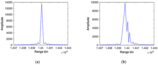
Figure 1.
The comparison of HRRP: (a) HRRP with an ideal channel; (b) HRRP with a non-ideal channel.
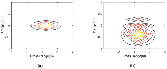
Figure 2.
The comparison of two-dimensional image: (a) Two-dimensional image with an ideal channel; (b) two-dimensional image with a non-ideal channel.
3. The Channel Calibration Method for Bistatic ISAR System
Channel calibration method based on a calibration tower at a fixed distance is effective for a monostatic ISAR system. SNR of the received signal is usually high because of the short distance and the gain of transponder. However, for the bistatic ISAR system, the baseline of the radar system is up to hundreds of kilometers. It is unrealistic to use a calibration tower to form the calibration loop. It is necessary to adopt this kind of target, which can be observed by bistatic radar system and can be regarded as a point target. The calibration satellite is also known as the standard spherical satellite, of which the RCS is generally within 1m2, and the echo signal is stable. The calibration for transmitting and receiving channels can be completed using calibration satellite echoes. Hence, a novel channel calibration method is proposed based on the calibration satellite.
3.1. Accumulation Method of Multi-Period Echoes
SNR of the calibration satellite echoes are low due to the small RCS and the long distance from the radar system. Hence, coherent accumulation of multiple-period echoes should be conducted to improve SNR. The coherent accumulation of multi-period echoes in the time domain is significant to estimate accurate channel transfer function. In addition, the calibration satellite is not a stationary target, and the impact of the high-speed motion needs to be compensated for. In a previous study [28], intra-pulse velocity compensation methods have been studied for the high-speed moving targets of bistatic ISAR. The velocity compensation method is used to compensate for the high-speed motion of the calibration satellite to make sure the echo signals satisfy the “stop and go” model for coherent accumulation.
The down-conversion of the calibration satellite echo is completed by the coherent local oscillator, and the baseband signal is obtained. The method proposed in [28] is used to compensate the intra-pulse velocity. Considering the non-ideal channel characteristics, the i-th echo signal in Equation (4) can be rewritten as:
where is the RCS of the calibration satellite, and is time delay, represents convolution operation, and is the transmitting and receiving channels’ impulse response in time domain.
After pulse compression using the matched filter, the signal can be expressed as:
where is the amplitude of the pulse compression result. In order to realize the coherent accumulation of the calibration satellite echo in the time domain, both the initial phase and zero frequency positions of the baseband echo signal in each period should be the same. The initial phase and zero frequency positions can be obtained through pulse compression. Comparing Equation (9) with Equation (10), the zero frequency position is equal to the peak position of the pulse compression result , and the initial phase is equal to the corresponding phase [18]. The phase compensation factors are calculated in accordance with the difference of initial phase compared with the first period , and original echoes of each period are compensated respectively. The central translation of echoes is achieved by circularly shifting according to the difference of peak position compared with the first period . Then, the coherent accumulation of echoes can be achieved by accumulating the adjusted echoes in the time domain. The process of coherent accumulation and the waveforms of accumulated signal at different stages are shown in Figure 3.
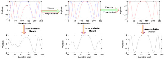
Figure 3.
The waveform of accumulated signal at different stages in the time domain.
3.2. Calibration Coefficient Construction
According to Equations (5) and (9), the frequency domain expression of the accumulated signal can be written as:
where is the time delay, which is equal to the time delay of the echo signal in the first period, and is the period number of the coherent period interval (CPI). The characteristics of the transmitting and receiving channels can be expressed as:
where reflects the peak position of the pulse compression results and the influence in each period is the same. In the process of calculating the calibration coefficient, this term can be ignored; is considered as a constant, and also can be ignored.
By using the reciprocal of Equation (12), the calibration coefficient of the channel can be obtained.
The compensation of non-ideal channel characteristics can be achieved by multiplying the echo frequency spectrum Equation (8) with the calibration coefficient Equation (13).
3.3. Calibration Process for Bistatic ISAR Imaging System
To illustrate the process clearly, the flow chart of proposed method for bistatic ISAR is shown in Figure 4.
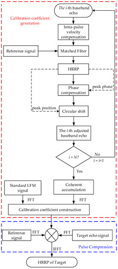
Figure 4.
Channel calibration flow chart for a bistatic ISAR system based on a calibration satellite.
The specific steps are as follows:
- Collect the i-th baseband echo of calibration satellite , and compensate the intra-pulse velocity to eliminate the influence of high speed motion.
- Use a matched filter to achieve the pulse compression, and obtain the peak position and the corresponding phase .
- Baseband echo data of is multiplied by to eliminate the influence of the random phase, the echo data center is aligned according to the peak position difference compared with the first period , and the adjusted echo is obtained.
- Repeat step 1–3 until the N-th baseband echo signal is adjusted.
- Coherently accumulate the adjusted baseband signals in time-domain and obtain the accumulated signal .
- Use MATLAB to generate the standard LFM baseband signal with the same time width, bandwidth, sampling rate and number of sampling points.
- Generate the calibration coefficient: .
- Before pulse compression, multiply the echo frequency spectrum Equation (8) with the calibration coefficient to achieve the channel calibration.
The calibration coefficient needs to be generated in advance. The characteristics of the channel are influenced by temperature, weather, humidity and other factors, it is not fixed. Therefore, the calibration coefficient needs to be updated before imaging.
4. Experimental Results and Analysis
This section demonstrates the performance of the proposed calibration method for bistatic ISAR imaging systems using real calibration satellite echoes and simulated target echoes.
4.1. Estimation of Channel Characteristics
4.1.1. Parameters Specification
The system parameters of the bistatic ISAR imaging system are shown in Table 1.

Table 1.
System parameters of the bistatic ISAR.
The RIGIDSPHERE 2 (LCS4) was selected as the calibration satellite, as it is a standard spherical satellite. Its two line elements (TLE) are provided by the Space Surveillance Network (SSN) of America, which are listed in in Table 2.
Table 2.
TLE of RIGIDSPHERE 2 (LCS4) satellite (10 August 2018).
The epoch time of initial orbital elements is on 10 August 2018 at 20:24:39.85. Setting transmitting station at the city Beijing and the receiving station at the city Nanjing. The visible time slots for the bistatic radar is from 22:08:46 to 22:21:19. The calibration satellite echoes are collected during the visible segment.
4.1.2. Results and Analysis
Real calibration satellite echoes are used to estimate the channel characteristics. We used 1000 periods of real calibration satellite echoes to improve the SNR in coherent accumulation process. Figure 5 is the waveform and spectrum of a real calibration satellite echo signal in one period. The signal was submerged in noise, since the RCS of LCS4 is only 0.947 m2 and the transmitting and receiving distance was around 1800 km. Figure 6 shows the waveform and spectrum of the signal, which was coherently accumulated by 1000 consecutive periods of real calibration satellite echoes in the time domain. The signal and noise can be distinguished in Figure 6a. As described in Section 3, the SNR in was improved to 12 dB and more accurate information of channel characteristic can be obtained via coherently accumulating in the time domain. Moreover, it can be seen that the waveform and spectrum of echoes are not ideal LFM signals, due to the modulation of the non-ideal channel characteristics.
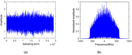
Figure 5.
Real calibration satellite echo signal in one period: (a) Real part of the signal; (b) spectrum of the signal.
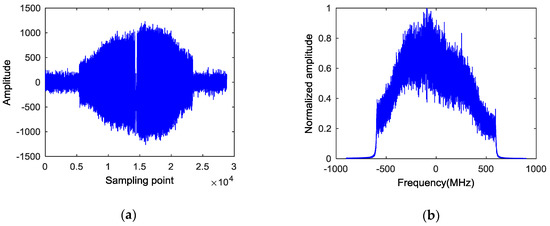
Figure 6.
Signal coherently accumulated 1000 periods of real calibration satellite echoes: (a) Real part of the signal; (b) spectrum of the signal.
4.2. Verification of the Channel Calibration Performance
4.2.1. Parameters Setting
The simulation scenario is shown in Figure 7, in which the red “◊” is the location of the transmitting station, the green “○” is the location of the receiving station, the length of the radar baseline is 50 km, the blue line is the target trajectory, the target velocity is 400 m/s, and the red part is selected as the imaging area. The simulation scatter-point model is shown in Figure 8.
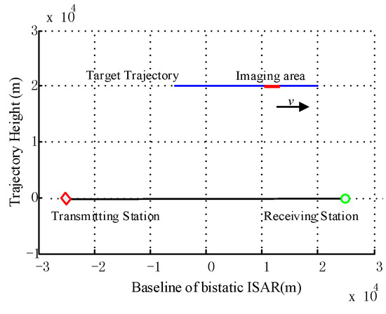
Figure 7.
Simulation scenario.
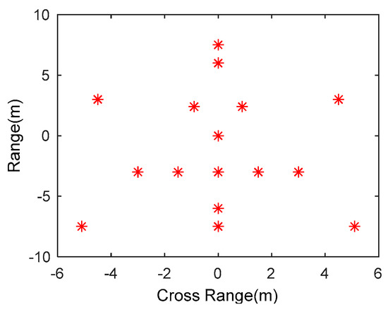
Figure 8.
Scatter-point model.
The parameters of a bistatic ISAR radar system used in simulation was same as the parameters of the radar system used to collect the real calibration satellite echoes in Section 4.1. The rest simulation parameters are shown in Table 3.
Table 3.
Simulation parameters.
4.2.2. Results and Analysis
The simulated non-ideal echoes of the scatter-point target in Figure 6 was generated by multiplying the spectrum of the target’s ideal LFM echo signal with the channel transfer function estimated by real satellite echo data in a specific CPI. The channel transfer function for calibration is estimated by real satellite echo data in another adjacent CPI. The ISAR two-dimensional image without channel calibration is shown in Figure 9a. The two-dimensional ISAR image with channel calibration based on the single period echo and echoes of 1000 consecutive periods are shown in Figure 9b,c respectively. For comparison, Figure 9d shows the image of the target without adding non-ideal channel characteristics. As shown in Figure 9a, the image is defocused and the scatter points are split and broadened, due to the channels non-ideal characteristics and no channel calibration. Because of the low SNR using a single period echo, in Figure 9b the calibration coefficient cannot fully reflect the channel characteristics. Even if the channel calibration is conducted, the image quality cannot be improved effectively. On the contrary, the image is deteriorated due to the influence of noise. In Figure 9c, we coherently accumulated the calibration satellite echoes of consecutive 1000 periods and obtained the calibration coefficient. After channel calibration, the image quality was improved. Compared with Figure 9d, the image Figure 9c is similar to the ISAR image without adding non-ideal channel characteristics, which indicates that the proposed method effectively eliminates the influence of the non-ideal channel.
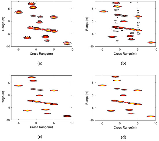
Figure 9.
ISAR two-dimensional images achieved through different processing methods: (a) Adding channel non-ideal characteristics and without channel calibration; (b) adding channel non-ideal characteristics and the channel calibration using single period echo; (c) adding channel non-ideal characteristics and the channel calibration using signal accumulated 1000 periods; (d) without adding non-ideal channel characteristics in echoes.
To analyze the performance of proposed calibration method quantitatively, Table 4 shows the image contrast of the four images in Figure 9. The image contrast of the ISAR image using proposed channel calibration method was better than the image without channel calibration and channel calibration using single period echoes. It was close to the image with an ideal channel, which demonstrates the effectiveness of proposed channel calibration method based on accumulated calibration satellite echoes.
Table 4.
The image contrasts of ISAR images in Figure 9.
5. Conclusions
An effective and feasible channel calibration method only using echo information for bistatic ISAR imaging systems with LFM waveform is proposed. The alignment method of multi-period echoes in the time domain according to the pulse compression result is provided. The SNR of the satellite echoes was improved through the coherent accumulation of multi-period echoes in the time domain, which provides the foundation for estimating accurate channel transfer function. The channel calibration coefficient is constructed based on the channel transfer function estimated by the accumulated signal. The channel calibration process for the system is presented based on the calibration satellite echoes. Simulation based on real satellite echoes confirms that the proposed method can effectively compensate non-ideal channel characteristics and improve the image quality.
Author Contributions
Conceptualization, L.S. and B.G.; data curation, L.S., B.G. and J.M.; formal analysis, C.S. and H.Z.; funding acquisition, C.S.; investigation, J.M.; methodology, L.S. and B.G.; resources, H.Z.; software, J.M.; validation, L.S.; writing—original draft, L.S.; writing—review and editing, C.S. and H.Z.
Funding
This research was funded by National Natural Science Foundation of China under Grant 61601496.
Acknowledgments
The authors would like to thank the editors and peer reviewers for their valuable comments and suggestions.
Conflicts of Interest
The authors declare no conflicts of interest.
References
- Yang, Z.Q.; Zhang, Y.; Luo, Y. Bistatic (Multistatic) Radar System; Defense Industry Press: Beijing, China, 1998. [Google Scholar]
- Chen, V.C.; Martorella, M. Inverse Synthetic Aperture Radar Imaging: Principles, Algorithms and Applications; SciTech Publishing: Edison, NJ, USA, 2014. [Google Scholar]
- Martorella, M.; Palmer, J.; Littleton, B.; Longstaff, I.D. On bistatic inverse synthetic aperture. IEEE Trans. Aerosp. Electron. Syst. 2007, 43, 1125–1134. [Google Scholar] [CrossRef]
- Comblet, F.; Khenchaf, A.; Baussard, A.; Pellen, F. Bistatic synthetic aperture radar imaging: Theory, simulations, and validations. IEEE Trans. Antennas Propag. 2006, 54, 3529–3540. [Google Scholar] [CrossRef]
- Ma, C.; Yeo, T.S.; Guo, Q.; Wei, P. Bistatic isar imaging incorporating interferometric 3-d imaging technique. IEEE Trans. Geosci. Remote Sens. 2012, 50, 3859–3867. [Google Scholar] [CrossRef]
- Chen, V.C.; Rosiers, A.D.; Lipps, R. Bi-static ISAR Range-Doppler Imaging and Resolution Analysis. In Proceedings of the 2009 IEEE Radar Conference, Pasadena, CA, USA, 4–8 May 2009; pp. 1–5. [Google Scholar]
- Martorella, M.; Cataldo, D.; Brisken, S. Bistatically equivalent monostatic approximation for bistatic ISAR. In Proceedings of the 2013 IEEE Radar Conference, Ottawa, ON, Canada, 29 April–3 May 2013; pp. 1–5. [Google Scholar]
- Li, Y.; Fu, Y.; Zhang, W. Distributed isar subimage fusion of nonuniform rotating target based on matching fourier transform. Sensors 2018, 18, 1806. [Google Scholar] [CrossRef] [PubMed]
- Bai, X.; Zhou, F.; Xing, M.; Bao, Z. Scaling the 3-d image of spinning space debris via bistatic inverse synthetic aperture radar. IEEE Trans. Geosci. Remote Sens. Lett. 2010, 7, 430–434. [Google Scholar] [CrossRef]
- Martorella, M. Analysis of the robustness of bistatic inverse synthetic aperture radar in the presence of phase synchronisation errors. IEEE Trans. Aerosp. Electron. Syst. 2011, 47, 2673–2689. [Google Scholar] [CrossRef]
- Pan, X.; Wang, W.; Feng, D.; Liu, Y. On deception jamming for countering bistatic isar based on sub-nyquist sampling. IET Radar Sonar Navig. 2014, 8, 173–179. [Google Scholar] [CrossRef]
- Ma, J.; Gao, M.; Guo, B.; Dong, J.; Xiong, D. High resolution inverse synthetic aperture radar imaging of three-axis-stabilized space target by exploiting orbital and sparse priors. Chin. Phys. B 2017, 26, 459–471. [Google Scholar] [CrossRef]
- Guo, B.; Wang, J.; Gao, M.; Shang, C.; Fu, X. Research on spatial-variant property of bistatic ISAR imaging plane of space target. Chin. Phys. B 2015, 24, 048402. [Google Scholar] [CrossRef]
- Zhang, S.; Sun, S.; Zhang, W.; Zong, Z.; Yeo, T. High-Resolution Bistatic ISAR Image Formation for High-Speed and Complex-Motion Targets. IEEE J. Sel. Top. Appl. Earth Obs. Remote Sens. 2017, 8, 3520–3531. [Google Scholar] [CrossRef]
- Kang, B.; Bae, J.; Kang, M.; Yang, E.; Kim, K. Bistatic-isar cross-range scaling. IEEE Trans. Aerosp. Electron. Syst. 2017, 53, 1962–1973. [Google Scholar] [CrossRef]
- Xu, G.; Xing, M.; Zhang, L.; Duan, J.; Chen, Q.; Bao, Z. Sparse apertures isar imaging and scaling for maneuvering targets. IEEE J. Sel. Top. Appl. Earth Obs. Remote Sens. 2014, 7, 2942–2956. [Google Scholar] [CrossRef]
- Zhao, L.; Gao, M.; Martorella, M.; Stagliano, D. Bistatic three-dimensional interferometric isar image reconstruction. IEEE Trans. Aerosp. Electron. Syst. 2015, 51, 951–961. [Google Scholar] [CrossRef]
- Cumming, I.; Wong, F. Digital Signal Processing of Synthetic Aperture Radar Data: Algorithms and Implementation; Artech House: Norwood, MA, USA, 2004. [Google Scholar]
- Deng, Y.; Zheng, H.; Wang, R.; Feng, J.; Liu, Y. Internal calibration for stepped-frequency chirp sar imaging. IEEE Trans. Geosci. Remote Sens. Lett. 2011, 8, 1105–1109. [Google Scholar] [CrossRef]
- Hung, E. Matrix-construction calibration method for antenna arrays. IEEE Trans. Aerosp. Electron. Syst. 2000, 36, 819–828. [Google Scholar] [CrossRef]
- Brunfeldt, D.; Ulaby, F. Active Reflector for Radar Calibration. IEEE Trans. Geosci. Remote Sens. 1984, 22, 165–169. [Google Scholar] [CrossRef]
- Doring, B.; Looser, P.; Jirousek, M.; Schwerdt, M. Reference Target Correction Based on Point Target SAR Simulation. IEEE Trans. Geosci. Remote Sens. 2012, 50, 951–959. [Google Scholar] [CrossRef]
- Döring, B.J.; Schmidt, K.; Jirousek, M.; Rudolf, D.; Reimann, J.; Raab, S.; Antony, J.W.; Schwerdt, M. Hierarchical Bayesian Data Analysis in Radiometric SAR System Calibration: A Case Study on Transponder Calibration with RADARSAT-2 Data. Remote Sens. 2013, 5, 6667–6690. [Google Scholar] [CrossRef]
- Döring, B.J.; Schwerdt, M. The radiometric measurement quantity for SAR images. IEEE Trans. Geosci. Remote Sens. 2013, 51, 5307–5314. [Google Scholar] [CrossRef]
- Luscombe, A.P.; Thompson, A.A. RADARSAT-2 Calibration: Proposed Targets and Techniques. In Proceedings of the IEEE International Geoscience and Remote Sensing Symposium, Vancouver, BC, Canada, 24–29 July 2001; pp. 496–498. [Google Scholar]
- Luscombe, A. Image Quality and Calibration of RADARSAT-2. In Proceedings of the IEEE International Geoscience and Remote Sensing Symposium, Cape Town, South Africa, 12–17 July 2009; pp. 757–760. [Google Scholar]
- Xiong, D.; Zhang, X.; Wang, J.; Zhao, H.; Gao, M. Reception and calibration of bistatic sf isar imaging system with wideband receiver. IET Radar Sonar Navig. 2017, 11, 379–385. [Google Scholar] [CrossRef]
- Guo, B.; Shang, C. Research on bistatic ISAR coherent imaging of space high speed moving target. In Proceedings of the IEEE Workshop on Electronics, Computer and Applications, Ottawa, ON, Canada, 8–9 May 2014; pp. 205–209. [Google Scholar]
© 2018 by the authors. Licensee MDPI, Basel, Switzerland. This article is an open access article distributed under the terms and conditions of the Creative Commons Attribution (CC BY) license (http://creativecommons.org/licenses/by/4.0/).