Abstract
Micropatterning technology offers powerful methods for biological analyses at the molecular level, enabling the investigation of cell heterogeneities, as well as high throughput detection. We herein propose an approach for single-cell patterning. The substrate was prepared using micro fabrication and surface modification processes, and the patterning template was prepared using bovine serum albumin and streptavidin, which can be employed for the patterning of any biological molecules containing biotin. Subsequent to photolithography, etching, chemical vapor deposition (CVD), and polyethylene glycol (PEG) treatment, the optimized patterns were obtained with high accuracy, strong contrast, and good repeatability, thus providing good foundations for the subsequent single-cell patterning. The surface passivation method was proven effective, preventing unwanted binding of the antibodies and cells. Based on this streptavidin template, the specific binding between the biotinylated antibodies and the antigens expressed on the surface of the cells was enabled, and we successfully achieved single-cell patterning with a single-cell capture rate of 92%. This single-cell array offers an effective method in the investigation of cell heterogeneity and drug screening. Further, these methods can be used in the final step for the screening and enrichment of certain cells, such as circulating tumor cells.
1. Introduction
Miniature analyzing systems have made significant progress with the rapid development of microelectronics and biomedical technologies [1,2]. Compared to traditional biomedical technologies, they have the advantages of high sensitivity, high throughput, rapidity, and low cost, indicating usefulness in in vitro tests and diagnoses [3,4]. Based on micropatterning technology, one can manipulate and detect objects on the molecular level, through which the biological responses and biochemical reactions can be analyzed in more detail, thus promoting the development of modern biomedical technologies [5,6,7].
Traditional cell detection methods typically involve a large number of cells, and the signal measured is the average information of such cells, neglecting the differences among different cells. Relevant biomedical research indicates that a considerable number of diseases, including leukemia, liver cancer, and Alzheimer’s, are caused by a minute number of pathogenic cell subpopulation [8,9,10]. Such important cell information is often overlooked in traditional cell detection methods, and even leads to some missing or wrong diagnoses [11,12]. Therefore, the heterogeneities among single-cell and small cell groups are crucial in such cases. Single-cell capture and separation for further single-cell analysis and research is paramount to modern biomedical research and clinical diagnoses [13,14,15]. Combining it with different nanoprobes, we can investigate the cells’ heterogeneities in real time, based on intracellular changes on the molecular level [16,17,18,19].
Cell patterning technologies can be divided into top–down methods, such as photolithography [20,21], soft lithography [22,23], and jet patterning [24], and bottom–up methods, such as molecular self-assembly technology [25,26]. Other approaches were also involved in cell patterning [27,28,29]. Currently, micropatterning technology is typically achieved by a combination of such methods, instead of a particular method [30,31]. Meanwhile, cell patterning can also provide new choices in relative analyzing systems, which has been an active area in recent years. In 2016, a digital microfluidic programmable stencil (dMPS) was invented for protein and cell patterning. As the authors said, patterning biomolecules and cells on substrates is usually a prerequisite for biological analysis and cell studies [32]. In 2017, a novel cell patterning method was developed for freeform micropatterning of living cells into a cell culture medium using direct inkjet printing [33]. In 2018, tape-assisted photolithographic-free microfluidic chip cell patterning was studied for a tumor metastasis study. It was pointed out that micropatterning is one of the most efficient ways to study tumor development, because it can tune the distribution of cells with spatial and temporal control [34]. Also in 2018, a single cell patterning method was proposed for high throughput subcellular toxicity assay, which reports a new single cell array based toxicity assay, in which cell responses at population level, single cell level, and subcellular level can be obtained simultaneously at high throughput [35].
As a currently popular research topic, the enrichment and screening of circulating tumor cells (CTCs) is still a challenge, in which immune identification and acquisition is still the final step after microfluidic separations [36,37,38]. If it can be combined with single-cell patterning, more choices could be available in the following studies, which are favorable to achieve high-throughput analyses [39,40,41]. Immunocapture is not a totally new technology. However, it has not been effectively used in cell patterning. This paper provides an effective approach for single cell patterning based on immunocapture, including detailed procedures and parameters, which will be helpful for relevant applications.
2. Preparation of the Substrate for Single Cell Patterning
To realize cell separation and patterning specifically, we studied a biocompatible template using biotin–BSA (Bovine Serum Albumin) and streptavidin. Based on the immune reactions between the biotinylated antibodies and the antigens on the surface of the cell’s membrane, HL-60 cells were successfully patterned on the glass substrate.
2.1. Overall Process of Substrate Preparation for the Single-Cell Array
To achieve the chip for the single-cell patterning, its substrate should be prepared first. Here, the fabrication process was based on micro fabrication, including photolithography, chemical vapor deposition (CVD), dry etching, wet etching, and polyethylene glycol (PEG) passivation. Meanwhile, three primary processes were employed to prepare the chip substrate, including piranha wet etching, oxygen plasma etching, and hexamethyldisilazane (HMDS) CVD, through which the patterned substrate was obtained with a clear pattern and boundary.
The purpose of the substrate surface modification for the single-cell patterning is to prepare a lattice pattern of two different substrate properties, including the pattern and the background, which can be used for the selective adhesion of proteins. To be effectively bonded to the proteins, the target islands should exhibit the same hydrophobic properties as the proteins, while the background without the pattern should be treated with passivation agents to prevent the unwanted adhesion. HMDS, which is often used in integrated circuit processing to enhance adhesion, will react with the hydroxyl silicon structure on the surface of the SiO2 glass substrate and form siloxane. The HMDS-modified surface of the glass slide will be hydrophobic, which can be a better adhesive to the photoresist. The chemical reaction can be expressed as:
Here, we used HMDS as the first processing material in the template generation. Our experiments showed that the islands after HMDS treatment exhibit good hydrophobic properties, which are a strong adhesive to proteins, and the surface of the siloxane group is nontoxic to the bioactive substances.
To obtain the HMDS pattern, the CVD method was employed. First, the photoresist mask was formed by direct lithography. Next, the CVD process was employed, through which the areas not covered by the photoresist will react with HMDS, followed by photoresist release and passivation treatment. The whole surface modification process includes lithography, dry etching, wet etching, chemical vapor deposition, etc., as shown in Figure 1. The selection of the parameters of each process directly determines the quality of the pattern on the substrate.
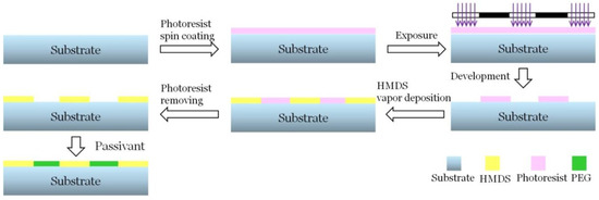
Figure 1.
Surfacemodification process of the substrate. The photoresist mask was formed by direct lithography and the chemical vapor deposition (CVD) process was employed, followed by photoresist release and passivation treatment. HMDS: hexamethyldisilazane; PEG: polyethylene glycol.
2.2. Surface Cleaning and HMDS Coating
The physical and chemical properties of the substrate materials exhibit various influences on the lithography process. Particles that are not removed on the surface owing to insufficient cleaning will lead to tails or pinholes in the photoresist pattern, thereby affecting the adhesion force between the photoresist and the substrate; therefore, pattern defects, such as floating photoresist, will be generated after the development. In addition, the chemical properties of the substrate surface directly affect the adhesion of the photoresist and the substrate, resulting in the decrease in the quality and accuracy of the pattern.
In our experiment, we found that the ultrasonic cleaning method cannot effectively remove the residues generated during the process, thereby resulting in the comet tail defect during the spinning process. Therefore, we used a piranha lotion (98% H2SO4 and 30% H2O2 mixed at a volume ratio of 7:3) in the ultrasonic cleaning for 10 min. Subsequently, the glass slide was rinsed with deionized water to remove the residues and blow dried using compressed air. The piranha lotion has a strong oxidation ability that can oxidize metal contaminants on the surface of the glass slide, thereby rendering them soluble in the solution. Meanwhile, the dehydration property of the sulfuric acid can carbonize organic substances, decomposing them into CO2 and H2O with the strong oxidizing abilities of hydrogen peroxide.
HMDS is a toxic, volatile, and colorless liquid that is harmful to human bodies. CVD is more suitable in this study, as the operator can be less exposed to HMDS. The primary concern is whether HMDS can penetrate the pores and react with the coated photoresist, and whether the additional heating process for photoresist drying will lead to difficulties in the photoresist release.
By measuring the contact angle of the deionized water on the surface of the slide, the hydrophobicity of the material surface can be characterized, and the coating properties of the substrate can be evaluated. The contact angle was measured using the OCA20 contact angle measurement instrument of DataPhysics, Fielderstadt, Germany. After dry cleaning, the contact angle of the glass slide was 18 ± 2°. After HMDS vapor deposition, the contact angle increased to 75 ± 4°, demonstrating strong hydrophobic properties. The principle and the test results of HMDS vapor deposition are shown in Figure 2.
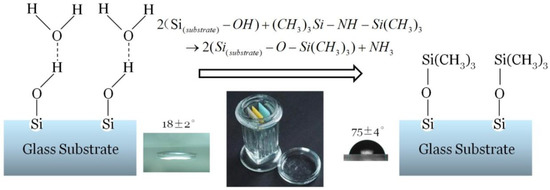
Figure 2.
Schematic diagram of hexamethyldisilazane (HMDS) vapor deposition. After HMDS vapor deposition, the contact angle increased to 75° ± 4°, demonstrating strong hydrophobic properties.
In the early experiments, we used the typical parameters of HMDS coating in microfabrications technology as the CVD parameters. In this setting, the slide was baked on a baker for 15 min at 150 °C; subsequently, it was quickly placed into the liquid containing a small amount (approximately 1 mL) of HMDS in an airtight flask for CVD. After 15 min of cooling, the CVD process was completed, and the substrate was removed for the following photoresist release process. With such parameters, owing to the high temperature, the fluidity of the photoresist is strong, thus leading to the blockage phenomenon in the holes with diameters from 9 μm to 10 μm.Further, owing to the thermal denaturation of the photoresist, the releasing process could not be fully accomplished, and the residual photoresist inhibited the grafting of the passivation agent, thus resulting in nonselective adhesion. In view of these patterning defects, in the HMDS CVD process, the temperature and the time of heat treatment must be reduced while effectively depositing a thin HMDS layer.
The substrate surface contact angle is related to the substrate cooling time in the HMDS steam. The contact angle will continue increasing with the processing time until the reaction is saturated and the substrate surface is completely modified. The continued increase in the cooling time will not further increase the contact angle.
We performed the experiments by varying the heating temperature and heating time, by heating the substrate under 110 °C and 150 °C for 20 s, 40 s, 60 s, 80 s, 100 s, 150 s, 200 s, 300 s, 400 s, 500 s, and 600 s at each temperature, and measuring the deionized water contact angles in different heating parameters; the results are shown in Figure 3. The contact angle was measured using the OCA20 contact angle measurement instrument of DataPhysics, Fielderstadt, Germany. Under these heating parameters, all the contact angles are between 71–79°.Considering measurement errors and surface irregularities, we conclude that, when the heating time is longer than 100s, the water contact angle will maintain in above range, and the surface processing quality is primarily related to the substrate cooling time in the HMDS vapor.
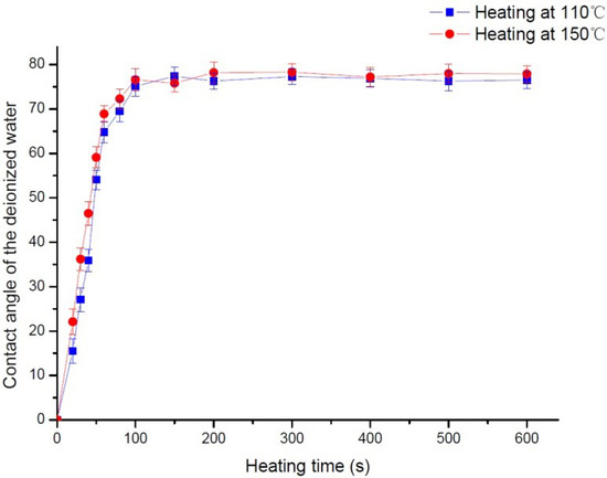
Figure 3.
Influence of the heating time on the surface contact angle. By varying the heating temperature and heating time, by heating the substrate under 110 °C and 150 °C for 20 s, 40 s, 60 s, 80 s, 100 s, 150 s,200 s, 300 s, 400 s, 500 s, and 600 s at each temperature, the deionized water contact angles were measured in different heating parameters.
To further investigate the significance of the difference of the water contact angle between different groups with different heating time, t-tests were conducted. The results are shown in Supplementary materials (Table S1). It can be seen that the p value between the group of 100 s and the groups of 60 s and 80 s is below 0.05, indicating the differences of the water contact angle between different groups with a different heating time were obvious. By contrast, the p value between the group of 100 s and the groups of 150 s, 200 s, 300 s, 400 s, 500 s, and 600 s is above 0.1, indicating the differences of the water contact angle between different groups with a different heating time were not obvious. Based on these experiment results and considering that the heating process results in hardbaking, the optimum settings for heating are 110 °C for 100 s, followed by immediate cooling in an HMDS vapor for 15 min.
2.3. PEG–Silane Passivation Process
The nonselective adhesion of the bovine serum protein in the following protein adhesion process renders the cleaning process difficult and the pattern quality degraded if the HMDS treated slides are not further treated. Here, we used poly(ethylene glycol)–silane (PEG–silane) as a passivator to treat the substrate with no siloxane groups, thus preventing it from bovine serum albumin adhesion. The contact angle test showed that the passivation treatment of PEG–silane did not affect the HMDS self-assembled molecular layer formed on the slide. Here, the contact angle was also measured using the OCA20 contact angle measurement instrument of DataPhysics, Fielderstadt, Germany.
With the high hydrophilic polymer chain, PEG can significantly reduce the adhesion of hydrophobic proteins on the substrate. Its reaction mechanism is shown in Equation (2). PEG–silane passivation technology is extremely simple: It only requires the immersion of the slide in the solution containing PEG–silane for 2–4 h to complete PEG–silane grafting on the exposed glass surface, to form a relatively hydrophilic self-assembling molecular layer.
The authors of [42] conducted a study on the concentration of the PEG–silane solution, and concluded that PEG–silane exhibited a better passivation effect at 10 mM concentration, which is in accordance with our experiment results. Here, we used the PEG–silane {2-[Methoxy(Polyethyleneoxy)Propyl]TrimethoxySilane} from Gelest, and the molecular weight is 459–591. In this experiment, 1 mM to 10 mM of PEG–silane solution was added in the anhydrous toluene solution, and 1% of triethylamine catalyst solution was also added. Subsequently, the substrate was immersed in the solution at room temperature for 2 h. Subsequently, it was ultrasonically cleaned with toluene for 5 min, followed by rinsing with isopropyl alcohol and deionized water, and drying. The contact angle test showed that the substrate with a 1 mM concentration of PEG solution passivation has a smaller contact angle, which is 46° ± 3°, while the contact angle of the substrate treated with the 10 mM concentration of PEG is 42° ± 3°, as shown in Figure 4.

Figure 4.
Changes in surface contact angle before and after poly(ethylene glycol) (PEG) passivation. The contact angle without passivation is 68° ± 3°. The contact angle of the substrate with a 1 mM concentration of PEG solution passivation is 46°±3°, and the contact angle of the substrate treated with the 10 mM concentration of PEG is 42° ± 3°. (a) Treatment without passivation. (b) Passivation with PEG–silane concentration of 1 mM. (c) Passivation with PEG–silane concentration of 10 mM.
Figure 5shows the fluorescence micrograph after the adhesion of bovine serum protein and streptavidin. The left image is the result of passivation in the PEG–silane solution with the concentration of 1 mM, and the right figure is the passivation result of the 10 mM solution. The background of the left image shows nonselective adhesion, and the nonselective adhesion in the contrast pattern on the right is lower. We further investigated the result of PEG passivation. We found that the HMDS self-assembled molecular layers can enhance protein adhesion, while the substrate after PEG passivation inhibited protein adhesion well (Supplementary materials Figure S1).
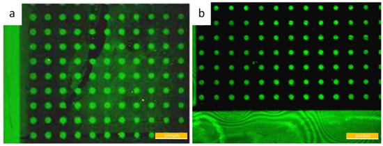
Figure 5.
(a) The pattern after the passivation with the PEG–silane concentration of 1 mM. (b) The pattern after the passivation with the PEG–silane concentration of 10 mM.
Finally, the passivation process was determined, in which the substrate was immersed in PEG–silane solution of concentration 10 mM for 2 h.
The parameters optimization results of the substrate preparation process for single-cell patterning are shown in Table 1.

Table 1.
The optimized processing parameters for the substrate of single-cell patterning. HMDS: hexamethyldisilazane; CVD: chemical vapor deposition. PEG: polyethylene glycol.
The prepared substrate was analyzed using a scanningelectron microscope, as shown in Figure 6. It is indicated that the largest pattern diameter is 72 μm, and the smallest one is 8.4 μm, both of which are in accordance with the parameters (70 μm, 9 μm) designed in the mask. The errors of the diameter are below 7%.
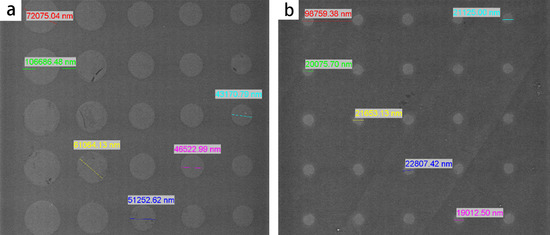
Figure 6.
Prepared substrate observed by the scanning electron microscope. (a) The large patterns with diameters from 42 μm to 72 μm. (b) The small patterns with diameters around 20 μm.
3. Single Cell Patterning
The substrate surface after micro fabrication and the relevant treatment can be divided into the hydrophilic part and hydrophobic part, in which the hydrophobic part is used to adhere the proteins. Bovine serum protein is a type of protein with surface adsorption characteristics, and has strong affinity with the hydrophobic surface. It is difficult to be rinsed by general processes when it is adsorbed on the hydrophobic surface. Therefore, using bovine serum protein as the substrate surface adsorption protein, we can obtain good adsorption consistency on the hydrophobic surface.
In our experiment, we used biotin bovine serum albumin (biotin–BSA) as the underlying adhesive proteins and streptavidin as the middle template layer to provide further binding sites for the following biotinylated biological molecules. Streptavidin is a type of globular protein with four biotin binding sites (two symmetrical pairs), and the affinity between biotin and streptavidin is strong. Via the BSA–biotin–Streptavidin (SA) connections, we converted the patterned surface with hydrophilic and hydrophobic areas into a surface with streptavidin patterns. This is also an effective tool for protein patterning.
In the middle of the BSA–biotin–SA-based template layer, we bonded CD45 and CD15 antibodies, separately, which are both expressed on the membrane of the HL 60 cells. Based on the specific immune reaction between antigens and antibodies, the HL 60 cells can be further captured on the surface of the substrate.
The single-cell patterning principle based on a surface modified substrate is shown in Figure 7.
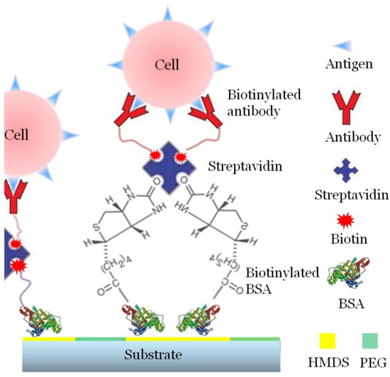
Figure 7.
Schematic diagram of single cell patterning. Biotin–BSA is employed as the underlying adhesive proteins. Streptavidin is the middle template layer to provide further binding sites for the bonding of the antibodies. Based on the specific immune reaction between antigens and antibodies, the HL 60 cells can be further captured on the surface of the substrate.
3.1. Materials
Cell
The acute promyelocytic leukemia cells (HL-60) were provided by Professor Yinye Wang of the Department of Molecular and Cellular Pharmacology, the Medical School of Peking University, China.
Reagents
- (1)
- RPMI-1640 (containing glutamine and HEPES (N-2-hydroxyethylpiperazine-N-2-ethane sulfonic acid) with concentration of 25 mM), Mai Chen Technology, Ltd., Beijing, China.
- (2)
- Newborn bovine serum, Gibco, Newyork, USA.
- (3)
- Penicillin–streptomycin solution 100×, Mai Chen Technology, Ltd., Beijing, China.
- (4)
- Phosphate buffered saline, PBS, Macgene Technology Ltd., China.
- (5)
- Trypan blue solution, Mai Chen Technology, Ltd., Beijing, China.
- (6)
- Biotin–BSA, Gelest, Morrisville, PA, USA.
- (7)
- Streptavidin Alexa Fluor 488 conjugate, Invitrogen, Carlsbad, CA, USA.
- (8)
- Anti-human CD15 Biotin, eBioscience, San Diego, CA, USA.
- (9)
- Anti-human/mouse CD45R (B220) Biotin, eBioscience, San Diego, CA, USA.
3.2. Experiments
3.2.1. Biotin–BSA Adsorption
An appropriate amount of Biotin–BSA solution was added in deionized water (2 mg/mL) to obtain a solution of 50 μg/mL. Subsequently, the solution was transferred to a glass slide using a pipette until the whole slide surface was covered. After 30 min of incubation at room temperature, the liquid residues were removed using a pipette. Finally, the substrate was immersed and cleaned in phosphate buffered saline (PBS) twice, with the pattern layer facing downwards.
3.2.2. Bonding of Straptavidins
The appropriate amount of biotinylated streptavidin solution (2 mg/mL) was added into PBS to obtain a concentration of 20 μg/mL. Subsequently, the solution was transferred to a glass slide using a pipette until the whole slide surface was covered. Wrapped with aluminum foil to avoid light influence, it was incubated at room temperature for 15 min. Finally, the substrate was immersed and cleaned in PBS twice.
3.2.3. Biotin–Antibody Immobilization
The appropriate quantity of biotinylated antibodies (2 mg/mL) was added into PBS to obtain a solution of 10 μg/mL. Subsequently, the solution was transferred to the glass slide until the whole slide surface was covered. Wrapped with aluminum foil to avoid light influence, it was incubated at room temperature for 15 min. Finally, the substrate was immersed and cleaned in PBS twice.
3.2.4. HL-60 Cells Seeding
Before the experiment, the cells were cultured with the cell culture medium, which is prepared with RPMI-1640 culture medium containing HEPES, 10% of newborn bovine serum and 1% of Penicillin–Streptomycin Solution. HEPES is a biocompatible buffer and is harmless to cells. The culture medium containing HEPES can be helpful for the longtime maintenance of a constant PH range. It can also effectively prevent the influence of PH fluctuation on cell growth.
For the generation of HL-60 cells array, HL-60 cells were collected and centrifuged at 500 g for 4.5 min and resuspended in PBS, through which a cell suspension was prepared with the concentration of 5 × 10⁶ cells/mL. The adequate amount of the suspension was loaded to the surface of the substrate until full coverage. After an incubation of 30 min, the liquid residues were removed using a pipette, and the substrate was immersed and cleaned in PBS twice. The prepared substrate was removed and placed into a Petri dish for observation under a fluorescence microscope.
The affinity between antibodies and antigens is relatively weak, and the bond is easily broken under external forces. However, the cells are affected by various factors in the patterning process. The cell seeding and rinsing process should be meticulously performed to avoid excessive external forces. The following processing parameters, including the time and the cell concentration in seeding, will affect the quality of single-cell patterning.
3.3. Results and Discussions
3.3.1. Patterning Results of Streptavidins
The substrate that has been incubated with streptavidins was observed under a fluorescence microscope, as shown in Figure 8, in which the pattern is clear and with high contrast. The maximum diameter of the arrayed dots is 72 μm, and the minimum diameter is 8 μm. The error is less than 7%, and dot losses do not exist.
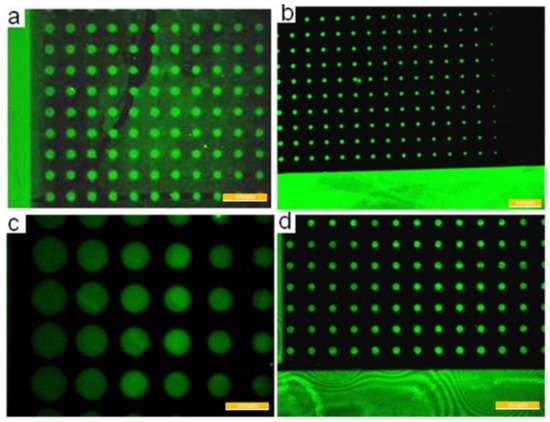
Figure 8.
Streptavidin patterning results. The largest diameter is 72 μm and the smallest diameter is 8.4 μm. It can be seen that the Streptavidin patterning results is very good. (a) Patterns with big diameters. (b) Patterns with smallest diameters. (c) Patterns with largest diameters. (d) Patterns with middle diameters.
3.3.2. HL-60 Cell Seeding Results
(1) Selection of antibodies.
The cell seeding result is shown in Figure 9, where the green fluorescence is the patterning result of the streptavidins. The cells were stained with red cell membrane marker DiIC18(3). The yellow fluorescence was the superposition effect of the red fluorescence and the green fluorescence. Owing to the strong binding ability between the streptavidins and biotins, CD15 antibodies can be effectively patterned. The red dots are the fluorescence produced by the cells under excitation, and shows that the cells are in disorder. No cells are present, either on the arrayed patterns or on the bar frame with larger dimensions. The expression rate of CD15 antigens on the surface of the HL-60 cells was investigated, and the experimental results show that this antigen is low expressed on the HL 60 cells, that is, only approximately 22% (Supplementary materials Figure S2).
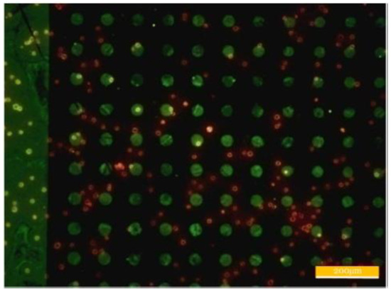
Figure 9.
Patterning results of CD15 antibodies and HL-60 cells.
To obtain good single-cell patterns, it is necessary to use antigens that are high expressed on the surface of the HL-60 cells.HL-60 is a promyelocytic leukemia cell with immaturity and is easy to be differentiated under the influence of various environment factors, thus leading to the change in cell-membrane-expressed antigens. In such cases, only suitable typical expressed antigens can guarantee the expression in the differentiated HL-60 cell lines. CD45 is a typical antigen of leucocyte, which is widely found on the surface of white blood cells. Therefore, we chose biotinylated CD45 antibodies as the direct binding proteins for the cells seeding. To test the binding effect of CD45, the same experiment was conducted with CD45 on a substrate with no features, indicating good capture results (Supplementary materials Figure S3).
(2) Cell concentration.
Cell concentration will affect the subsequent cleaning process and the patterning results. Real-time observation under a microscope indicated that when the cell concentration is extremely high, the cells will gather during incubation. Therefore, when removing the uncaptured cells with the subsequent cleaning process, the captured cells will likely be rinsed, thus leading to pattern defects. Meanwhile, when cell concentration is extremely low, the cells cannot cover the substrate surface, thus leading to vacancies in patterning.
The diameter of the HL-60 cell is between 10 μm and 12 μm. Suppose that the cells are compactly spread over the substrate, and using 10 μm as cells’ diameter, the cells’ density when covering 1 cm2 area should be the following: (1 cm/10 µm)2/1 cm2 = 1 × 10⁶/cm2. According to experience, each layer of the cell in suspension generally occupies 2 mm in depth; subsequently, the cell concentration covering the whole surface should be 1 × 10⁶/(2 mm × 1 cm2) = 5 × 10⁶/mL. In practice, the concentration in cell patterning could be slightly lower than the calculated value (Supplementary materials Figure S4).
The mediums and buffers were all standard solutions. The experiments were conducted at room temperature (24–28 °C). There is no obvious difference in the binding ratio and yield.
(3) Time of cell seeding
The time of cell seeding is determined by the reaction time of the surface antigens and antibodies. If the seeding time is extremely short, the antigen–antibody reaction will be insufficient, thus leading to the failure of some pattern islands. If the seeding time is extremely long, the cells that have not been caught may be attached on the surface of the substrate with nonselective adhesion, thus resulting in difficulties in the subsequent cleaning process. The experiments were conducted with the seeding times of 10, 20, 30, 40, and 50 min, and the pattern with a large feature size was employed as the observing area to reflect the antigen–antibody reactions. It was indicated that almost all the full patterns were covered with the seeding time of 30 min. Therefore, we chose 30 min as the seeding time in the following experiments.
(4) The influence of geometric parameters on single-cell capture rate.
For most cases, we aim to develop single-cell patterning chips. When the patterning islands become larger, more cells tend to be immobilized on one island. Meanwhile, if the island is extremely small, only a few cells could be captured on the island. Therefore, the relationship between the number of cells captured and the diameters of the patterns was investigated. According to the analyses above, the seeding concentration was still 5 × 10⁶ cells/mL. Figure 10 shows the ratios of the patterning islands capturing no cells, only one cell, two, or more than two cells. It is indicated that when the diameter of the islands is less than 10 μm, the streptavidin on each island was insufficient to capture the cell. Meanwhile, when the islands are larger than 30 μm, two or more cells appear on most islands. The islands with diameters between 15–25 μm are the optimal ones to capture only one cell, and are favorable for forming single-cell patterning chips. CD45 was used in this experiment.
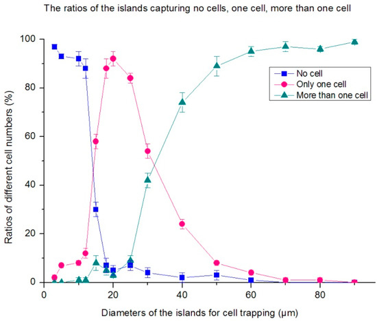
Figure 10.
The ratios of patterning islands capturing no cells, only one cell, two, or more than two cells. It is indicated that the islands with diameters between 15–25 μm are the optimal ones to capture only one cell, and are favorable for forming a single-cell patterning chips.
(5) Patterning results
According to the methods above, HL-60 cells with good cell activity were used and prepared for cell suspension with the concentration of 5 × 10⁶ cells/mL. We took the cell suspension 100 μL to the centrifuge tubes of 0.5 mL, added antihuman CD45 Biotin 2 μL to it, and fully blended the antibodies with the cell suspension. After 30 min incubation at room temperature, centrifuging was conducted for 5 min at the speed of 1000 rpm. Subsequently, the supernate was extracted, and 500 μL PBS was added for rinsing; this was repeated thrice. Finally, 100 μL of PBS and 2 μL of biotinylated streptavidin solution were added and fully blended. After 30 min incubation at room temperature, 100 μL of PBS was dropped in a Petri dish for observations via a fluorescence microscope. HL-60 cell lines were patterned on the glass substrate, and the results are shown in Figure 11, with the single-cell capture rate of 92%.
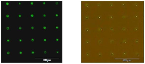
Figure 11.
Single cell patterning results of HL-60 cells. Left: The fluorescence image after the patterning of antibodies. Right: HL-60 patterning results (the photo under both the bright field and the fluorescence excitation).
The biocompatibility of the fabrication and the surface modification processes was tested using HL-60 cells in the RPMI-1640 media, supplemented with FBS and antibiotics for 10 h. After 10 h, the cells were still in the former patterned area. Meanwhile, cell viability was evaluated using Trypan blue staining. The results are shown in Figure S5. It can be seen that more than 93% of the cells were still alive after 10 h, indicating good biocompatibility.
4. Conclusions
In this paper, a method for single-cell patterning was studied, based on immunocapture on a MEMS-processed substrate. The experimental results showed that this method could also be used to pattern antibodies. After the optimizations of the cell seeding time, cell concentration, and cell cleaning method, the patterning of single HL-60 cells was achieved.
This method could be used in the final step of screening and in the enrichment of certain cells, such as CTCs. Based on this method, we can integrate the processes of cell sorting and cell patterning into one procedure; this is beneficial in improving the accuracy of CTC screening and to facilitate the following analyses, especially the cells heterogeneity analysis.
Furthermore, owing to the cell surface antigen specificity, we could choose different antibodies for the patterning of different cells, through which the synchronous screening and positioning of different cells could be achieved; this is useful for the contrast experiments of these cells, as well as for high-throughput drug screening. For example, we can investigate the mechanical characteristics of tumor cells and leukocytes. Using this method, we can design a chip to pattern tumor cells and leukocytes at the same time from the tissue cell suspension, simplifying the patterning process.
Meanwhile, part of the procedures could also be applied in antibody/protein patterning, which is easier than cell patterning. Such antibody/protein arrays could be employed for the in vitro test of some diseases, such as the early diagnosis of tumors.
Supplementary Materials
The following are available online at http://www.mdpi.com/2076-3417/8/11/2152/s1, Figure S1: Adhesion of proteins on the substrates. Table S1: T-test of the Influence of the heating time on the surface contact angle. Figure S2: Observation of CD15 expressions. Figure S3: Observation of the immunocapture of HL-60 cells based on CD45 antigens. Figure S4: Cells coverage under the cell concentration of 5 × 10⁶ cells/mL. Figure S5: Ratio of the live cells after 10 h.
Author Contributions
D.A. optimized the process, analyzed the data, and wrote the paper; M.C. designed the methods, performed the experiments, and optimized the parameters; J.W. performed the experiments of single-cell patterning based on immunocapture. The first two authors contributed equally to this paper.
Funding
This work is supported by the National Program for Significant Scientific Instruments Development of China (No. 2011YQ030134).
Acknowledgments
The authors would also thank the support of the State Key Laboratory of Precision Measurement Technology and Instruments.
Conflicts of Interest
The authors declare no conflict of interest.
References
- Nuxol, E. BioMEMS in drug delivery. Adv. Drug Deliv. Rev. 2013, 65, 1611–1625. [Google Scholar] [CrossRef] [PubMed]
- Lilienthal, K.; Fischer, M.; Stubenrauch, M.; Schober, A. Self-organized nano structures in silicon and glass for MEMS, MOEMS and BioMEMS. Mater. Sci. Eng. B 2010, 169, 78–84. [Google Scholar] [CrossRef]
- Ren, D.; Wang, J.; Wang, B.; You, Z. Probes for biomolecules detection based on RET-enhanced fluorescence polarization. Biosens. Bioelectron. 2016, 79, 802–809. [Google Scholar] [CrossRef] [PubMed]
- Lan, S.; Veiseh, M.; Zhang, M. Surface modification of silicon and gold-patterned silicon surfaces for improved biocompatibility and cell patterning selectivity. Biosens. Bioelectron. 2005, 20, 1697–1708. [Google Scholar] [CrossRef] [PubMed]
- Albisettiab, E.; Pettia, D.; Daminb, F.; Cretichb, M.; Tortia, A.; Chiarib, M.; Bertaccoa, R. Photolithographic bio-patterning of magnetic sensors for biomolecular recognition. Sens. Actuators B Chem. 2014, 200, 39–46. [Google Scholar] [CrossRef]
- Wang, B.; Chen, Z.; Ren, D.; You, Z. A novel dual energy transfer probe for intracellular mRNA detection with high robustness and Specificity. Sens. Actuators B Chem. 2019, 279, 342–350. [Google Scholar] [CrossRef]
- Pal, R.K.; Kurland, N.E.; Wang, C.; Kundu, S.C.; Yadavalli, V.K. Biopatterning of silk proteins for soft micro-optics. ACS Appl. Mater. Interface 2015, 7, 8809–8816. [Google Scholar] [CrossRef] [PubMed]
- Lawson, D.A.; Bhakta, N.R.; Kessenbrock, K.; Prummel, K.D.; Yu, Y.; Takai, K.; Zhou, A.; Eyob, H.; Balakrishnan, S.; Wang, C.Y.; et al. Single-cell analysis reveals a stem-cell program in human metastatic breast cancer cells. Nature 2015, 526, 131–135. [Google Scholar] [CrossRef] [PubMed]
- Smith, C.C.; Paguirigan, A.; Jeschke, G.R.; Lin, K.C.; Massi, E.; Tarver, T.; Chin, C.S.; Asthana, S.; Olshen, A.; Travers, K.J.; et al. Heterogeneous resistance to quizartinib in acute myeloid leukemia revealed by single-cell analysis. Blood 2017, 130, 48–58. [Google Scholar] [CrossRef] [PubMed]
- Mazutis, L.; Gilbert, J.; Ung, W.L.; Weitz, D.A.; Griffiths, A.D.; Heyman, J.A. Single-cell analysis and sorting using droplet-based microfluidics. Nat. Protoc. 2013, 8, 870–891. [Google Scholar] [CrossRef] [PubMed]
- Yin, H.; Marshall, D. Microfluidics for single cell analysis. Curr. Opin. Biotechnol. 2012, 23, 110–119. [Google Scholar] [CrossRef] [PubMed]
- Ren, D.; Xia, Y.; You, Z. Multiplexed living cells stained with quantum dot bioprobes for multiplexed detection of single-cell array. J. Biomed. Opt. 2013, 18, 1–9. [Google Scholar] [CrossRef] [PubMed]
- Villani, A.C.; Satija, R.; Reynolds, G.; Sarkizova, S.; Shekhar, K.; Fletcher, J.; Griesbeck, M.; Butler, A.; Zheng, S.; Lazo, S.; et al. Single-cell RNA-seq reveals new types of human blood dendritic cells, monocytes and progenitors. Science 2017, 356, 4573. [Google Scholar] [CrossRef] [PubMed]
- Angermueller, C.; Clark, S.J.; Lee, H.J.; Macaulay, I.C.; Teng, M.J.; Hu, T.X.; Krueger, F.; Smallwood, S.A.; Ponting, C.P.; Voet, T.; et al. Parallel single-cell sequencing links transcriptional and epigenetic heterogeneity. Nat. Methods 2016, 13, 229–232. [Google Scholar] [CrossRef] [PubMed]
- Buettner, F.; Natarajan, K.N.; Casale, F.P.; Proserpio, V.; Scialdone, A.; Theis, F.J.; Teichmann, S.A.; Marioni, J.C.; Stegle, O. Computational analysis of cell-to-cell heterogeneity in single-cell RNA-sequencing data reveals hidden subpopulations of cells. Nat. Biotechnol. 2015, 33, 155–160. [Google Scholar] [CrossRef] [PubMed]
- Ren, D.; Wang, J.; Wang, B.; You, Z. Quantum dot probes for cellular analysis. Anal. Methods 2017, 9, 2621–2632. [Google Scholar] [CrossRef]
- Hanif, S.; Liu, H.L.; Ahmed, S.A.; Yang, J.M.; Zhou, Y.; Pang, J.; Ji, L.N.; Xia, X.H.; Wang, K. Nanopipette-based SERS aptasensor for subcellular localization of cancer biomarker in single cells. Anal. Chem. 2017, 89, 9911–9917. [Google Scholar] [CrossRef] [PubMed]
- Wang, B.; Ren, D.; You, Z.; Yalikun, Y.; Tanaka, Y. Ultrasensitive detection of nucleic acids based on dually enhanced fluorescence polarization. Analyst 2018, 143, 3560–3569. [Google Scholar] [CrossRef] [PubMed]
- Chokkalingam, V.; Tel, J.; Wimmers, F.; Liu, X.; Semenov, S.; Thiele, J.; Figdor, C.G.; Huck, W.T.S. Probing cellular heterogeneity in cytokine-secreting immune cells using droplet-based microfluidics. Lab Chip 2013, 13, 4740–4744. [Google Scholar] [CrossRef] [PubMed]
- Winkelmann, M.; Gold, J.; Hauert, R.; Kasemo, B.; Spencer, N.D.; Brunette, D.M.; Textor, M. Chemically patterned, metal oxide based surfaces produced by photolithographic techniques for studying protein- and cell-surface interactions I: microfabrication and surface characterization. Biomaterials 2003, 24, 1133–1145. [Google Scholar] [CrossRef]
- Ren, D.; Xia, Y.; Wang, J.; You, Z. Micropatterning of single cell arrays using PEG-Silane and Biotin-(Strept)Avidin System by photolithography and chemical vapor deposition. Sens. Actuators B Chem. 2013, 188, 340–346. [Google Scholar] [CrossRef]
- Lim, C.T.; Zhang, Y. Novel dome-shaped structures for high-efficiency patterning of individual microbeads in a microfluidic device. Small 2007, 3, 573–579. [Google Scholar] [CrossRef] [PubMed]
- Bogdanski, N.; Wissen, M.; Möllenbeck, S.; Scheer, H.C. Polymers below the critical molecular weight for thermal imprint lithography. Microelectron. Eng. 2008, 85, 825–829. [Google Scholar] [CrossRef]
- Vaillancourt, J.; Zhang, H.; Vasinajindakaw, P.; Xia, H.; Lu, X.; Han, X.; Janzen, D.C.; Shih, W.S.; Jones, C.S.; Stroder, M.; et al. All ink-jet-printed carbon nanotube thin-film transistor on a polyimide substrate with an ultrahigh operating frequency of over 5 GHz. Appl. Phys. Lett. 2008, 93, 3301. [Google Scholar] [CrossRef]
- Wang, S.; Cai, X.; Wang, L.; Li, J.; Li, Q.; Zuo, X.; Shi, J.; Huang, Q.; Fan, C. DNA orientation-specific adhesion and patterning of living mammalian cells on self-assembled DNA monolayers. Chem. Sci. 2016, 7, 2722–2727. [Google Scholar] [CrossRef] [PubMed]
- Delapierre, F.D.; Mottet, G.; Taniga, V.; Boisselier, J.; Viovy, J.L.; Malaquin, L. High throughput micropatterning of interspersed cell arrays using capillary assembly. Biofabrication 2017, 9, 015015. [Google Scholar] [CrossRef] [PubMed]
- Liu, Y.; Ren, D.; Ling, X.; Liang, W.; Li, J.; You, Z.; Yalikun, Y.; Tanaka, Y. Time sequential single-cell patterning with high efficiency and high density. Sensors 2018, 18, 3672. [Google Scholar] [CrossRef] [PubMed]
- Espulgar, W.; Yamaguchi, Y.; Aoki, W.; Mita, D.; Saito, M.; Lee, J.K.; Tamiya, E. Single cell trapping and cell–cell interaction monitoring of cardiomyocytes in a designed microfluidic chip. Sens. Actuators B Chem. 2015, 207, 43–50. [Google Scholar] [CrossRef]
- Zhang, J.; Chen, F.; He, Z.; Ma, Y.; Uchiyama, K.; Lin, J.M. A novel approach for precisely controlled multiple cell patterning in microfluidic chips by inkjet printing and the detection of drug metabolism and diffusion. Analyst 2016, 141, 2940–2947. [Google Scholar] [CrossRef] [PubMed]
- Ren, D.; Wang, J.; You, Z. Long-term monitoring of Capase-3 activity in living cells based on the FRET probe composed of quantum dot, nanogold and EGF. RSC Adv. 2014, 4, 54907–54918. [Google Scholar] [CrossRef]
- Shrirao, A.B.; Kung, F.H.; Yip, D.; Firestein, B.L.; Cho, C.H.; Townes-Anderson, E. A versatile method of patterning proteins and cells. J. Vis. Exp. 2017, 120, e55513. [Google Scholar] [CrossRef] [PubMed]
- Gao, Y.; Tian, J.; Wu, J.; Cao, W.; Zhou, B.; Shen, R.; Wen, W. Digital microfluidic programmable stencil (dMPS) for protein and cell patterning. RSC Adv. 2016, 6, 101760–101769. [Google Scholar] [CrossRef]
- Park, J.A.; Yoon, S.; Kwon, J.; Now, H.; Kim, Y.K.; Kim, W.J.; Yoo, J.Y.; Jung, S. Freeform micropatterning of living cells into cell culture medium using direct inkjet printing. Sci. Rep. 2017, 7, 14610. [Google Scholar] [CrossRef] [PubMed]
- Zhao, L.; Guo, T.; Wang, L.; Liu, Y.; Chen, G.; Zhou, H.; Zhang, M. Tape-assisted photolithographic-free microfluidic chip cell patterning for tumor metastasis study. Anal. Chem. 2018, 90, 777–784. [Google Scholar] [CrossRef] [PubMed]
- Xia, J.; Qiu, Y.; Xun, X.; Ma, L.; Guan, J.; Su, M. Single cell patterning for high throughput sub-cellular toxicity assay. Anal. Chim. Acta 2018, 1007, 26–32. [Google Scholar] [CrossRef] [PubMed]
- Nivedita, N.; Garg, N.; Lee, A.P.; Papautsky, I. A high throughput microfluidic platform for size-selective enrichment of cell populations in tissue and blood samples. Analyst 2017, 142, 2558–2569. [Google Scholar] [CrossRef] [PubMed]
- Ohnaga, T.; Shimada, Y.; Takata, K.; Obata, T.; Okumura, T.; Nagata, T.; Kishi, H.; Muraguchi, A.; Tsukada, K. Capture of esophageal and breast cancer cells with polymeric microfluidic devices for CTC isolation. Mol. Clin. Oncol. 2016, 4, 599–602. [Google Scholar] [CrossRef] [PubMed]
- Chikaishi, Y.; Yoneda, K.; Ohnaga, T.; Tanaka, F. EpCAM-independent capture of circulating tumor cells with a ‘universal CTC-chip’. Oncol. Rep. 2017, 37, 77–82. [Google Scholar] [CrossRef] [PubMed]
- Launiere, C.; Gaskill, M.; Czaplewski, G.; Myung, J.H.; Hong, S.; Eddington, D.T. Channel surface patterning of alternating biomimetic protein combinations for enhanced microfluidic tumor cell isolation. Anal. Chem. 2012, 84, 4022–4028. [Google Scholar] [CrossRef] [PubMed]
- Ren, D.; Xia, Y.; Wang, B.; You, Z. Multiplexed Analysis for Anti-EGFR tumor cell growth inhibition based on QD probes. Anal. Chem. 2016, 88, 4318–4327. [Google Scholar] [CrossRef] [PubMed]
- Adams, D.L.; Zhu, P.; Makarova, O.V.; Martin, S.S.; Charpentier, M.; Chumsri, S.; Li, S.; Amstutz, P.; Tang, C.M. The systematic study of circulating tumor cell isolation using lithographic microfilters. RSC Adv. 2014, 9, 4334–4342. [Google Scholar] [CrossRef] [PubMed]
- Sharma, S.; Johnson, R.W.; Desai, T.A. XPS and AFM analysis of antifouling PEG interfaces for microfabricated silicon biosensors. Biosens. Bioelectron. 2004, 20, 227–239. [Google Scholar] [CrossRef] [PubMed]
© 2018 by the authors. Licensee MDPI, Basel, Switzerland. This article is an open access article distributed under the terms and conditions of the Creative Commons Attribution (CC BY) license (http://creativecommons.org/licenses/by/4.0/).