1. Introduction
Connected cars are attracting attention increasingly and several commercial products for the connected car are expected in the near future. After a dedicated spectrum at 5.9 GHz was allocated for intelligent transport systems (ITSs), both in the US and in Europe in 1999 and 2008, respectively, different families of standards have been developed: the IEEE/SAE dedicated short-range communication (DSRC) in 2010 in the US, Release 1 of the ETSI/CEN Cooperative-ITS (C-ITS) in 2013 in Europe, and 3GPP Cellular-V2X (C-V2X) in early 2017 as a feature of Release 14 of the LTE standard [
1,
2,
3,
4,
5,
6,
7]. DSRC and C-ITS both use the IEEE 802.11p standard [
4,
6,
7], which is a short-range technology for connected car communications, for the physical and data link layers [
4]. Based on the IEEE 802.11p standard, the SARTRE project, which ran from 2009 to 2012, deployed a platoon of multiple connected cars driven autonomously in close formation [
8]. In Japan, the fully automated truck platooning with a connected car system was tested on an express way in the Energy ITS project in 2012 [
9]. The European Truck Platooning Challenge demonstrated the automated trucks of six major truck vendors that were driven in platoons on public roads [
10].
Since currently wireless communication networks for connected cars are based on the IEEE 802.11p and wireless access in vehicular environments (WAVE) standards, the future wireless communication network for connected cars should provide a backward compatibility with IEEE 802.11p- and WAVE-based communication networks [
11,
12,
13].
To enhance the safety and user experience of next-generation autonomous vehicles, not only enhancements in signal processing but also wireless network-based ITSs have been developed [
14,
15]. To provide a wireless network-based ITS, vehicle-to-anything, denoted as V2X, communication systems are expected to be used in autonomous driving vehicles [
14,
15,
16,
17,
18]. V2X is a wireless communication technology used to exchange ITS information among cars, between a car and infrastructure network access points (APs), or among user devices in the car. Therefore, in the future V2X communication, from the V2X communication point of view, connected cars will include autonomous cars.
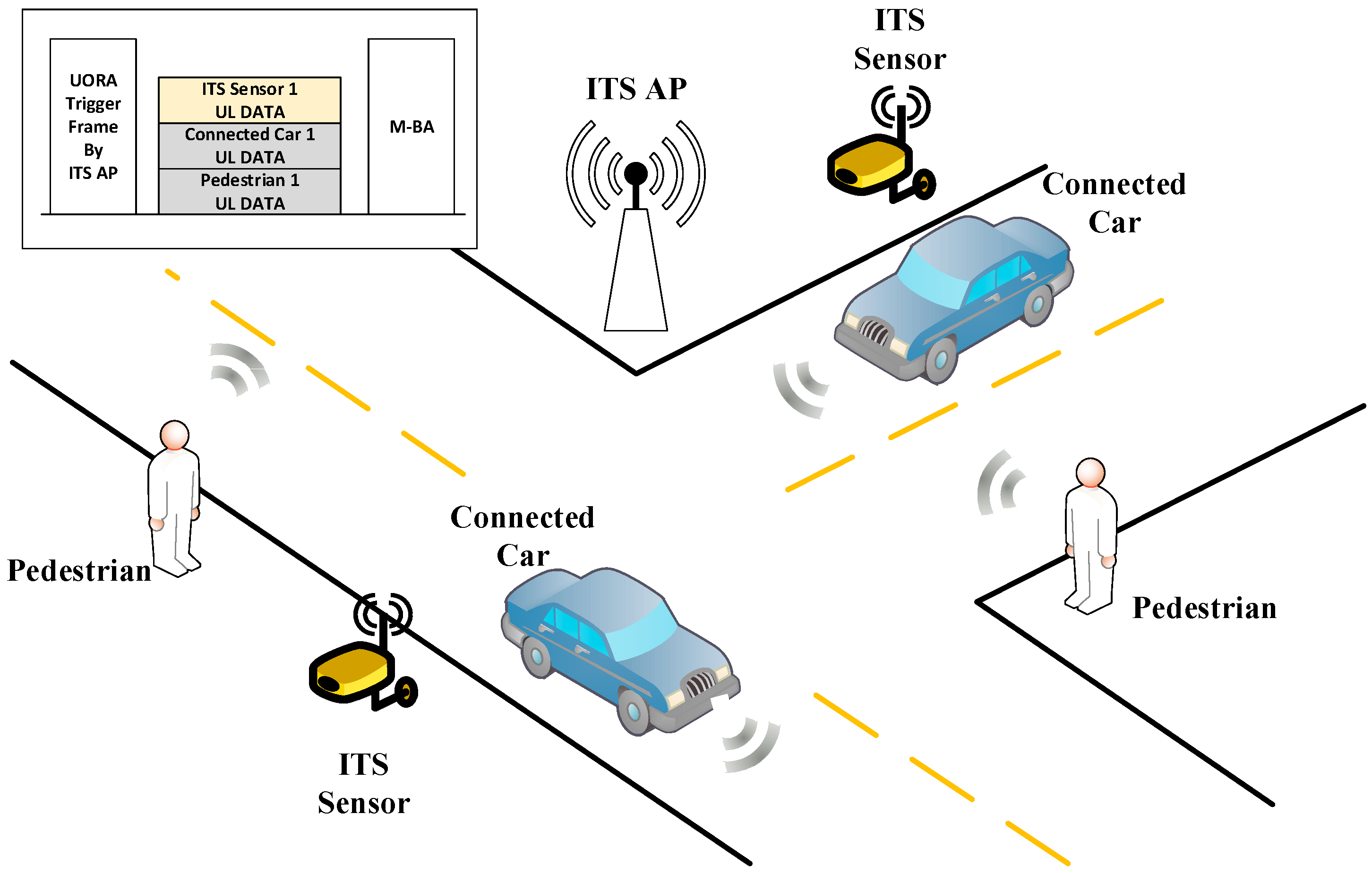
To effectively provide users with a comfortable and safe driving environment, the ITS AP shall be considered as an ITS sensor or an ITS beacon for every navigating connected car. In other words, the ITS AP shall accommodate ITS information from connected cars, ITS pedestrians, and some local sensors. Then, it shall transmit the information gathered and processed by the ITS AP or crucial ITS information received from a remote node, such as ITS service provider servers, remote vehicles to numerous ITS nodes including connected cars and ITS pedestrians by using its wired and wireless connections. Therefore, the numerous communication links between ITS nodes and an AP must be reliable and need to have low delay properties for the AP to perform the role of a reliable ITS beacon. Unfortunately, if the number of ITS nodes that an AP needs to support is too large, the ITS AP cannot establish those wireless connections rapidly in a random-access-based V2X network. Because connected cars have large mobility, the connection establishment delay caused by many ITS nodes in next-generation V2X networks is much more important than in other wireless network scenarios.
In this paper, the next-generation V2X (NG-V2X) scenario described in
Figure 1 is considered. ITS sensors are sensors collecting information related to ITS system. They can collect weather information, pavement condition information (road surface temperature, water film thickness, residual salt, etc.), and traffic information including vehicle classification [
19,
20]. They are anticipated to be used more widely for safety in various ITS scenarios in the future. The NG-V2X system must provide communications between a vehicle and anything including pedestrians, ITS sensors, vehicles, and ITS APs [
21,
22]. In another word, the NG-V2X must provide V2X communications. Thus, the NG-V2X system needs to consider communications among various and numerous stations (STAs) than ever before. Usually, 1000 m is considered as the ideal coverage range of an IEEE 802.11p-based system under the assumption of Line of Sight (LOS) communications environment like highway [
23,
24,
25,
26,
27] without considering obstacles and severe fading and shadowing, which is not a realistic scenario [
28]. It means that the IEEE 802.11p STAs can deliver data frames without any problem if there are not so many vehicles, as in a rural area or an uncrowded road unless there are shadowing and fading which can make the IEEE 802.11p coverage range smaller [
29,
30]. However, even though the actual coverage range is smaller than ideal coverage range of IEEE 802.11p-based system, the coverage range is sufficient to accommodate a large number of connected cars that could cause channel access problems in traffic jam scenarios because every car will be required to equip a V2X system in the near future [
31,
32,
33]. Furthermore, the NG-V2X network we consider may include various STAs including pedestrian STAs and ITS sensor STAs as shown in
Figure 1; this means that the NG-V2X network may suffer severe channel access problems without novel and efficient channel access schemes. In other words, supporting numerous V2X STAs including all cars required to be equipped with the V2X system, ITS pedestrians, and ITS sensors will be difficult without novel and efficient NG-V2X channel access schemes.
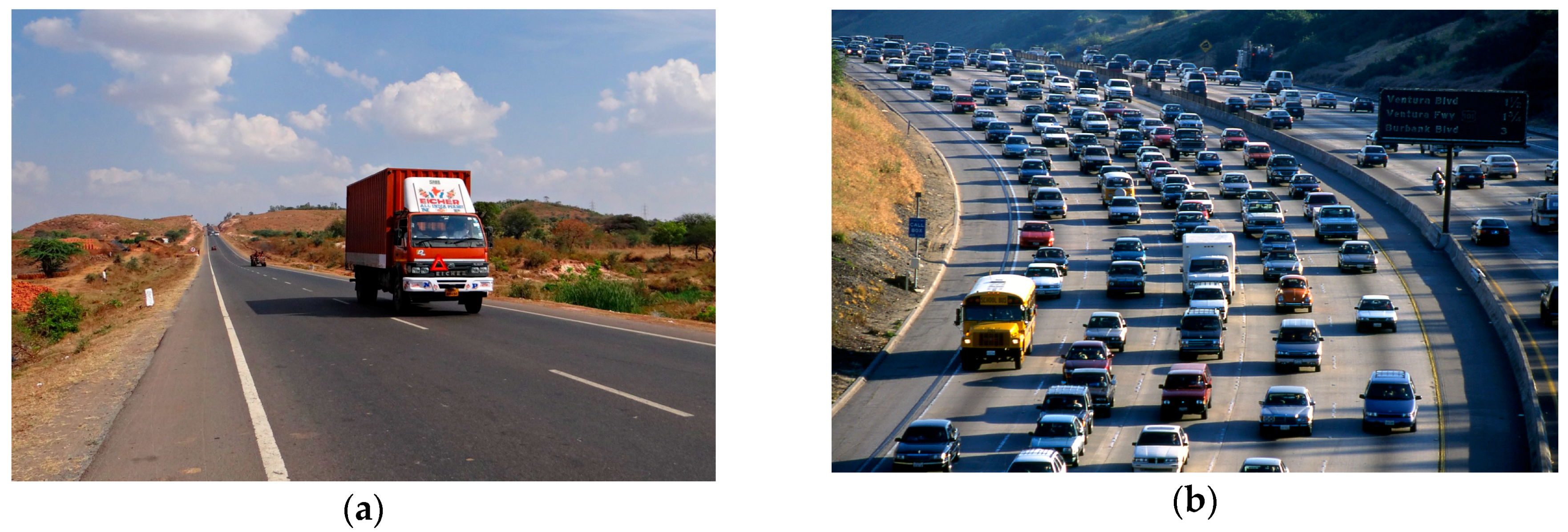
These kinds of scalability problems are the most well-known problems of wireless networks. However, different from other cases, downlink ITS information has a broadcast property and uplink ITS information may not require a large size of frames. Furthermore, the presence of a large number of connected cars in the area of an AP means that their mobility might be reduced than in usual cases, and hence the data frames become more delay tolerable. In other words, if there is no traffic jam, a connected car will pass through a coverage range of an ITS AP installed on the roadside in a short time. However, if there is a heavy traffic jam, the car cannot leave the coverage range soon.
Figure 2 shows the concept of these two scenarios. An ITS AP can be installed on the roadside and ITS sensors can be installed on the roadside or buried under the road for these two scenarios.
Figure 2a shows a sparse case, and
Figure 2b shows a dense case. In the
Figure 2a scenario, the initial channel access delay is important, not a collision. On the other hand, in the
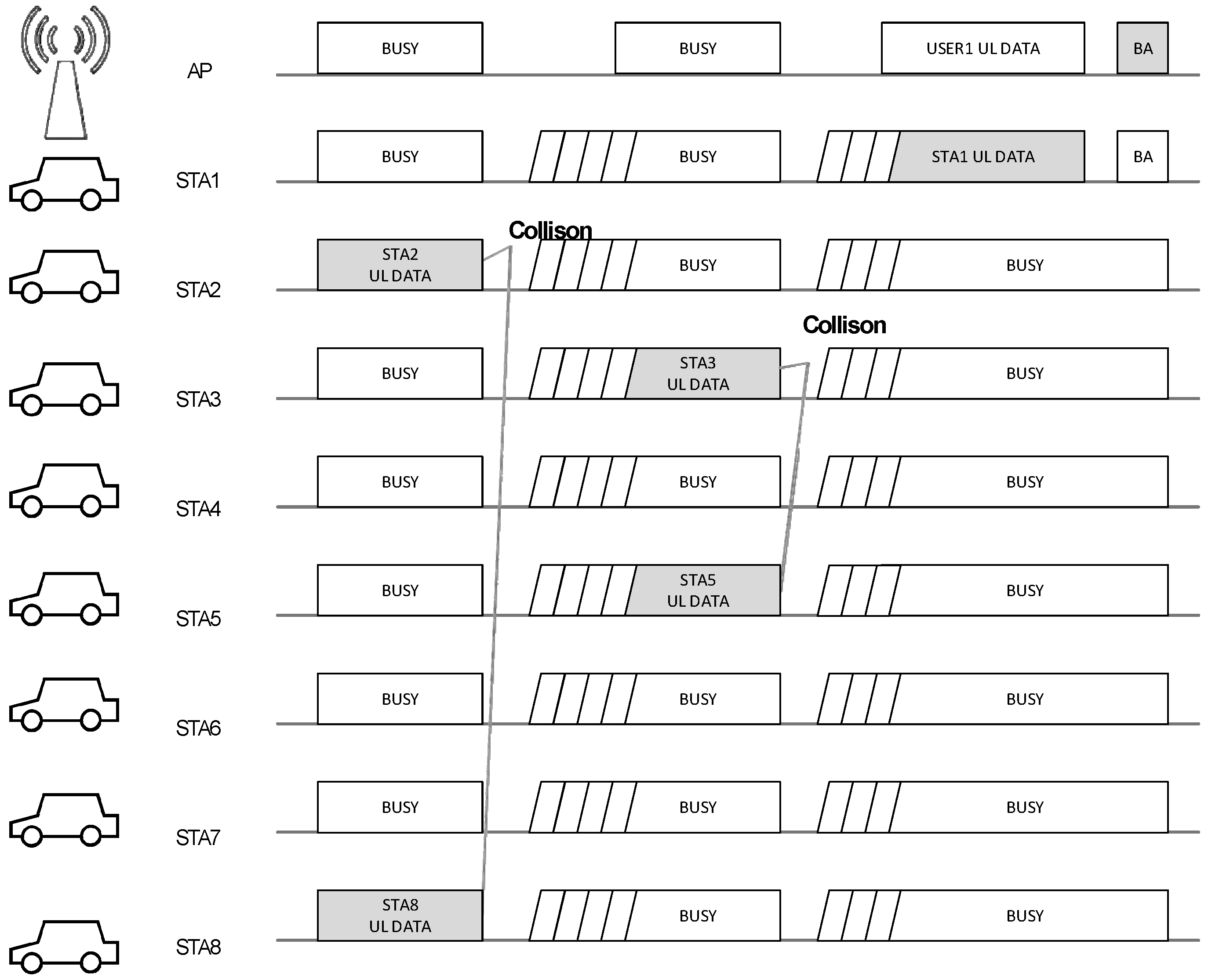
Figure 2b scenario, a collision may occur as shown in
Figure 3; after collision, an additional channel access delay needs to be considered because of the enhanced distributed channel access (EDCA) procedure of the IEEE 802.11 standard. It is worth noting that the delay after channel collision could be much longer than the data collision time. This means that the time loss due to collision, which is inevitable because random access is the only solution for a newcomer STA unless there were prior procedures such as an association or a dedicated resource scheduling, is not so long relatively, but the delay generated by random back-off after collision has a large value relatively. Hence, the random back-off delay needs to be minimized or eliminated for an effective channel access procedure.
In the design of the proposed scheme, two essential aspects, namely, backward compatibility and massive V2X support, are carefully considered. Since the IEEE 802.11p-based V2X network is already being deployed and used for ITSs, NG-V2X networks shall be designed under the consideration of the IEEE 802.11p-based V2X network to provide backward compatibility. Since all future cars are expected to be equipped with V2X communication devices, dense V2X communication scenarios will be common and massive V2X communication support will be required.
As part of the efforts to solve two challenging issues of V2X network, the IEEE 802.11 working group has started to study the NG-V2X system. A study group for NG-V2X (NGV-SG) has been formed to consider various scenarios for the V2X communication system. It is expected that the study group will produce an NG-V2X standard based on the conventional IEEE 802.11p standard to ensure backward compatibility. It is considering a V2X system that will be more reliable, have a higher capacity, and support higher mobility, though specific details of the requirements are being discussed.
In the proposed scheme, an IEEE 802.11-based extension is employed to provide backward compatibility, ability to operate in a mode in which the devices can interoperate with conventional IEEE 802.11p devices [
34], and the emerging IEEE 802.11ax standard-based orthogonal frequency-division multiple access (OFDMA) is adopted and extended to provide massive V2X support. This paper proposes a novel NG-V2X channel access scheme based on uplink OFDMA. Our main contributions in this paper consist of two parts: (1) a scalable and efficient channel access method using modified IEEE 802.11ax uplink OFDMA random access (UORA) appropriate for massive V2X support and (2) an accurate mathematical modeling and analysis on the adopted IEEE 802.11ax uplink OFDMA random access (UORA). The adopted IEEE 802.11ax-based OFDMA schemes including UORA for the proposed NG-V2X channel access is modified to work in 10 MHz channel bandwidth by doubling the symbol length of IEEE 802.11ax symbols. The operation frequency band of the proposed NG-V2X channel access scheme is the 5.9 GHz ITS band which is the same operation band as the conventional IEEE 802.11p based ITS systems. The proposed scheme includes a scalable channel access method appropriate for V2X applications, and it also enables effective communication between ITS sensors and ITS APs without impacting V2X system performance. Furthermore, a scheduled NG-V2X channel access scheme is also proposed for the extra optimization. To show how the proposed NG-V2X channel access scheme can enhance network scalability, mathematical modeling, and analysis, more accurate and closer to real standards than ever to the best of our knowledge on uplink OFDMA random access (UORA) are provided. In the mathematical modeling of UORA, some errors of the previous works are fixed and the actual UORA procedure of the IEEE 802.11ax standard is considered. Then, the delay and user capacity performance of the proposed NG-V2X channel access scheme, including some further optimization methods, are evaluated in various simulation scenarios to demonstrate how the proposed schemes enhance user capacity performance of the NG-V2X network.
The rest of paper is organized as follows. In
Section 2, we introduce some background technologies including the conventional IEEE 802.11p standard and UORA, which are used as a basic channel access concept in this work. In
Section 3, the proposed NG-V2X channel access scheme using the UORA procedure is explained. In
Section 4, mathematical models of UORA and novel and efficient V2X enhancing methods including scheduled NG-V2X channel access are explained. Since the proposed mathematical modeling of the UORA procedure considers the latest updates on UORA procedure of IEEE 802.11ax, the proposed modeling is the most up-to-date and accurate modeling to the best of our knowledge. The proposed NG-V2X scheme is specifically designed to transport ITS information in dense scenarios for the next-generation V2X networks. In
Section 4, the system performance of the proposed uplink V2X channel access is investigated through extensive simulation. In
Section 5, delay and packet loss rate performances are examined in various simulation scenarios including conventional IEEE 802.11p and high priority channel access scheme proposed by previous studies to compare the channel access schemes. The conclusion with a remark of relationship with NG-V2X is presented in
Section 6.
2. Background Technology
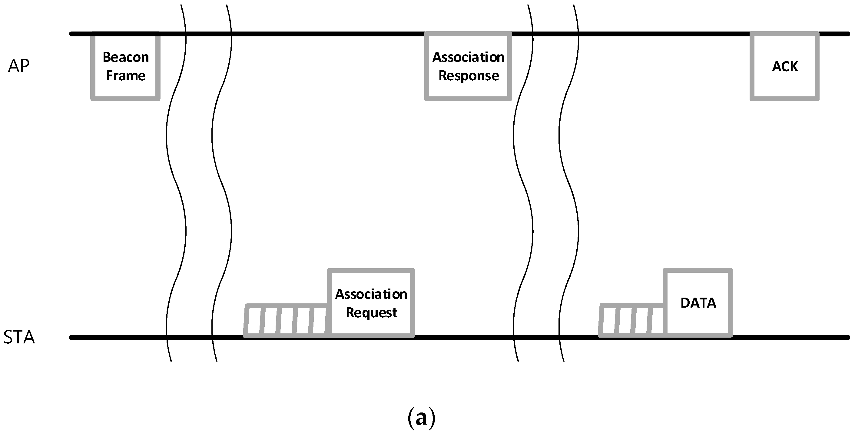
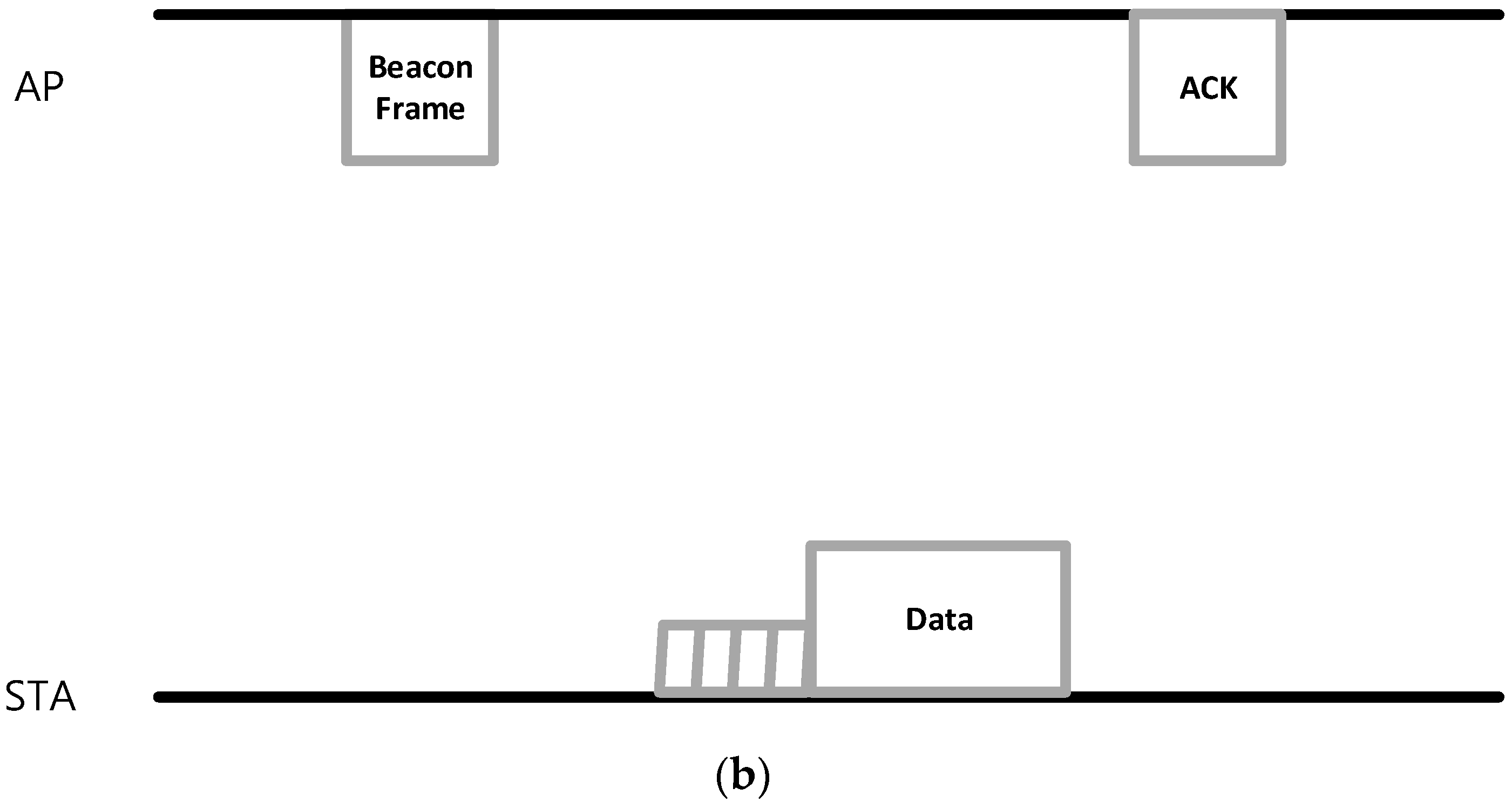
In the IEEE 802.11p standard, different from other IEEE 802.11 standards, authentication and association processes, which cause a large delay before real data transmission, are not required. Each IEEE 802.11p STA can transmit its data to an AP after receiving the beacon frame with the channel access procedure.
Figure 4 shows the conventional IEEE 802.11 transmission procedure with large delay link establishment and the IEEE 802.11p procedure with simplified link establishment. Although IEEE 802.11p has a simplified link establishment procedure, the channel access procedure is still time-based random access; hence, if multiple STAs transmit their data simultaneously, all the data frames collide in the air. Because the random-access-based channel access procedure of IEEE 802.11 is distributed and involves a large retransmission delay, it is not suitable for highly dense connected car scenarios like the interchange and urban traffic jam cases.
An uplink delay of IEEE 802.11p frame delivery can be described as
where
α represents the ratio of the partial control channel (CCH) duration if the frame arrives during the CCH duration.
M is the number of retransmissions until transmission success or failure.
N(
i) is the number of CCHs for each retransmission. If
i is 0, the value came from initial transmission.
TCCH_duration is a value of a CCH duration usually set to 50 ms or 0 ms.
TTXOP is a time component for transmitting a data frame and receiving its immediate response.
Tback-off represents a random delay during which an IEEE 802.11 STA must wait before transmitting its frames to avoid wireless channel collision. The back-off value is chosen randomly between 0 and the value of the congestion window (CW) size, and the STAs must reduce the back-off value every time slot interval if the channel is idle during the time slot and the value is positive.
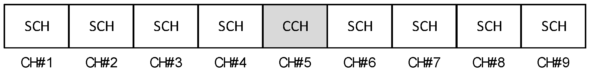
Because IEEE 802.11p could switch its logical channel repeatedly, an uplink channel access procedure by connected cars can be performed during the service channel (SCH) duration only. Basically, IEEE 802.11p could switch its logical channel every 50 ms. In IEEE 802.11p, there are two types of logical channel: CCH and SCH; CCH is used for transmitting downlink ITS information by an ITS AP, and SCH can be used for every ITS station if the STAs have received a beacon frame from the ITS AP. If a V2X system deploys a dedicated frequency channel for the logical CCH and SCH, the V2X delay,
TCCH_duration can be set to 0. In this case,
TV2X can be described as below.
Because recent V2X systems tend to use a dedicated channel structure rather than to use a channel switching structure in a single channel [
35,
36], we determined to use this dedicated CCH structure in this study.
Figure 5 describes an example of the channel structure considered in this study.
V2X systems consist of several components including vehicle-to-vehicle (V2V), vehicle-to-infrastructure (V2I), vehicle-to-device (V2D), etc., and V2V and V2I communications shall be operated in identical frequency bands if the V2X system is supported by a single communication protocol rather than using complex multiple vehicular communication systems. Only the channels in the bands can be diversified for each purpose. Some channels could be defined as CCHs, and others as SCHs. Some SCHs might be used for V2I, and others for V2V or a mixed purpose. As we mentioned earlier, the delay this paper focuses on is a V2I delay in an SCH. More specifically, this paper considers the V2I uplink delay in the SCH channel. Because each vehicle transmits its own frames to a V2X infrastructure STA without any centralized control, the delay and collision they cause could be a great threat against contention-based V2X systems.
Although the IEEE 802.11p standard is not a very recent standard, it is verified and being deployed for novel V2X systems. Although the latest research groups, including 3GPP and IEEE, are considering NG-V2X network standards, they are still considering IEEE 802.11p as the baseline technology for NG-V2X systems. Therefore, we consider IEEE 802.11p-based V2X channel access schemes for the NG-V2X systems in this work.
The NG-V2X system that we consider shall support backward compatibility to IEEE 802.11p. This means that if the SCH or CCH is used for both conventional IEEE 802.11p and NG-V2X, the existence of conventional IEEE 802.11p STAs needs to be considered and conventional IEEE 802.11p communication should not be adversely affected. This can be interpreted that the channel access scheme we propose needs to be examined under the scenarios of legacy IEEE 802.11 coexistence.
In this study, we propose a specific uplink channel access mechanism based on IEEE 802.11p. We consider highly dense scenarios of V2X vehicles in a traffic jam to measure how reliable and scalable the V2X system is in extreme scenarios. To handle the dense scenario, we have chosen to use the trigger frame that is defined in the IEEE 802.11ax standard but not in IEEE 802.11p. Basically, the trigger frame is used for soliciting uplink multiuser transmission by an STA whose address is indicated in the trigger frame. Because the trigger frame needs the target uplink STAs’ addresses, using the trigger frame for soliciting uplink multiuser transmissions in the V2X system that does not have an association procedure for exchanging STA information is not appropriate. Therefore, performing uplink multiuser transmission in the V2X system requires a random-access-based channel access procedure and not dedicated scheduling using the basic trigger frame. Fortunately, a resource unit (RU)-based random-access procedure called UORA procedure is defined in the IEEE 802.11 ax standard as an optional feature.
The UORA is a unique channel access scheme for allowing STAs to perform RU-based random access.
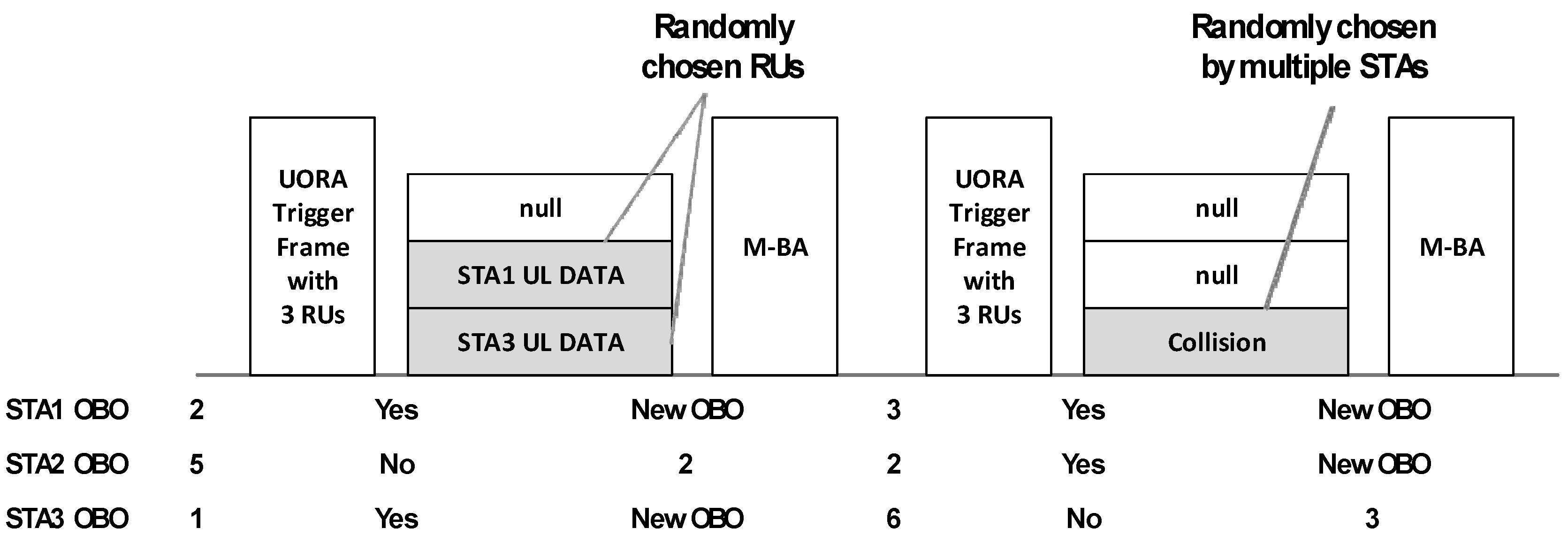
Figure 6 shows the basic concept and operation of the UORA procedure. In this procedure, the AP allows STAs to access some RUs indicated as UORA RUs, which are indicated by a special value of association ID (AID). If the AID of some RUs is written in the special AID value, any STA receiving the UORA trigger frame counts the number of UORA RUs. The number is used for decreasing the STAs’ back-off counter as in the conventional IEEE 802.11 distributed coordinating function back-off procedure. Unlike in the conventional procedure, the back-off counter decreases based on the number of RUs and not based on the number of time slots the STAs have waited.
Although the UORA procedure is not defined for IEEE 802.11p and hence cannot be used in the existing IEEE 802.11p-based V2X system, we propose to use the UORA procedure for the NG-V2X system by demonstrating its performance gain by proposing novel enhancing algorithms in this work.
3. Proposed Novel V2X Channel Access Schemes
The basic model of UORA channel access we considered in previous sections can be applied to a novel V2X channel access scheme. Because UORA channel access can be applied to non-AID STAs, IEEE 802.11p-based V2X STAs that do not have an association procedure to obtain an AID are good targets for applying the UORA channel access procedure.
In addition to conventional IEEE 802.11p and UORA channel access that we have considered, we consider a limited association procedure for enhancing the V2X system. Although the legacy V2X system considers communications between vehicles and other STAs, including V2X infrastructure STAs, other vehicles, etc., we can assume that some extra sensor STAs could be installed near a V2X infrastructure STA communicating with the V2X infrastructure STA in the NG-V2X scenario.
Sensor STAs may have extremely low or no mobility in contrast to V2X vehicular STAs. This means that the association procedure, which the conventional V2X system does not support due to the high mobility and short link lifetime of V2X STAs, can be useful for these V2X sensor STAs of NG-V2X. The sensor STAs deployed for accommodating traffic information could transmit the information to a V2X infrastructure STA. In many cases, the sensor STAs intend to report the information to certain V2X infrastructure STAs periodically. In this case, using random-access channel access mechanisms including DCF and UORA is very inefficient. To minimize the inefficiency, an association procedure between the V2X infrastructure STA and the sensor STAs for scheduled transmission opportunity needs to be considered. If the V2X system allows association procedures for some special STAs including the sensor STAs, V2X infrastructure STAs can allocate AIDs to the STAs. In this case, the V2X infrastructure STAs can trigger OFDMA transmissions of the special STAs by using a trigger frame with dedicated AIDs the V2X infrastructure STAs have allocated.
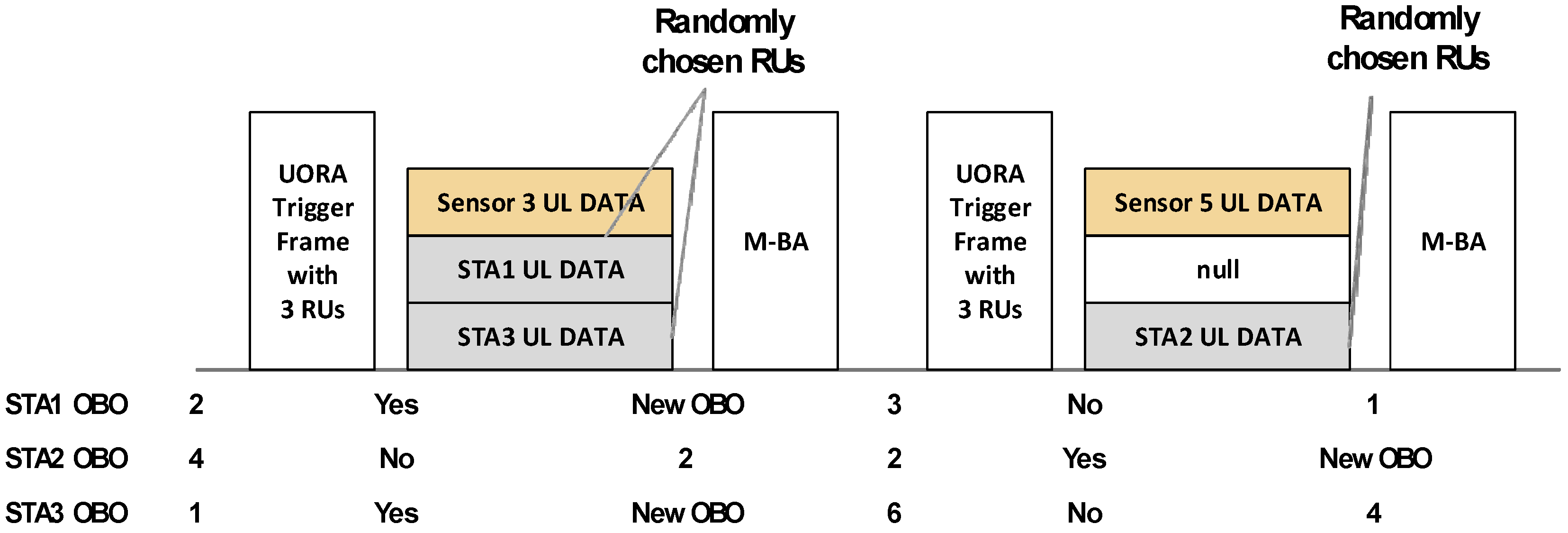
Figure 7 shows the UORA channel access procedure with dedicated AIDs. RUs with dedicated AIDs cannot be accessed by V2X-UORA STAs, and only the special STA having a unique dedicated AID can access the matched RU and transmit its own information. Unless dedicated RUs are used, the special STAs also need to participate in the contention procedure, causing longer system delay and higher packet loss rate. Therefore, to optimize V2X-UORA channel access, dedicated RU-based channel access with the association procedure needs to be considered to be applied.
For further optimization, we consider the scheduled NG-V2X system that we propose. The UORA trigger frame we use for NG-V2X is especially useful for soliciting uplink transmissions from multiple STAs. However, if a channel is determined to be used for UORA transmission and time sync is calibrated by other frames transmitted by an ITS AP, a beacon frame or a new indication frame is sufficient and the trigger frame is not required for the UORA channel access procedure. This means that the overhead caused by transmitting trigger frames can be eliminated so that the scheduled NG-V2X could achieve a higher user capacity threshold than the NG-V2X we considered.
4. System Model
Some researchers have tried to model the UORA procedure using a Markov chain model with some assumptions for simplified analysis in the early stage of IEEE 802.11ax standardization. As the IEEE 802.11ax standard has been developed, the specific procedure of UORA has been defined. To modify and correct the Markov model and the analysis method, Lanante et al. tried to generate a more generalized model and analysis method [
37]. Many researchers have tried to evaluate its performance, especially its efficiency and throughput [
38,
39]. One of the purposes of this paper is similar to that of those studies on system modeling. Because the research is almost close to the actual IEEE 802.11ax UORA procedure, a small disagreement still exists between the Markov chain model and the actual UORA procedure. Therefore, we tried to enhance the Markov model and the analysis method.
4.1. Markov Chain Model
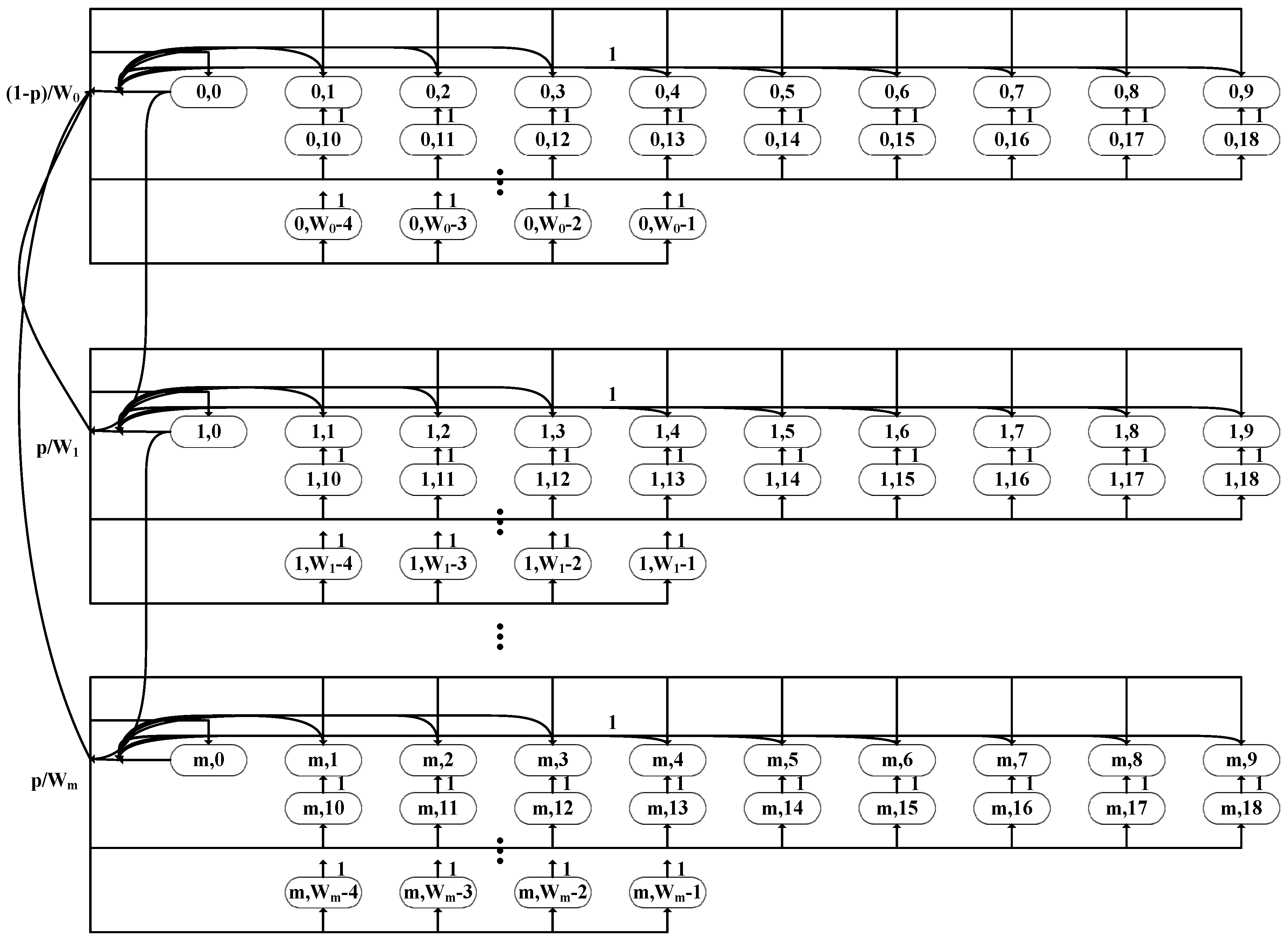
As an example, assume the UORA trigger frame with nine UORA RUs. Because the 20-MHz IEEE 802.11ax trigger frame can have nine RUs at most, this is a reasonable situation.
Figure 8 shows the Markov chain model of the 9-RU UORA procedure. If the UORA counter of an STA is smaller than the number of UORA RUs in the received trigger frame, the STA can transmit its frame via the UL OFDMA transmission opportunity. If the initial random back-off number the STA obtained is 0 or smaller than the number of UORA RUs in the trigger frame, the STA can transmit its frame just after receiving the trigger frame with UORA RU(s). Based on
Figure 8, each probability branch can be described as below.
where
m is the required number of retransmissions to reach the maximum UORA CW size. The maximum UORA CW size is called OCWmax and the initial size of UORA CW is called OCWmin. Once the OCW reaches OCWmax for successive retransmission attempts, the OCW,
Wi in (3), shall remain at the value of OCWmax,
Wm in (3), until the OCW is reset. The probability
p means the probability of transmission failure when an STA transmits its frame via the UORA procedure. If we assume that the transmission is always successful unless there are collisions,
p can be interpreted as the probability of UORA collision.
From the Markov chain model and probability branches, we can derive the stationary distribution of the Markov chain.
From the state (0,0), the following can be derived:
For each state (0,
k) where
k > 0, we can derive the following expression.
For 0 <
i <
m,
k > 0, the expression for each
can be derived as below.
From Equations (5) and (7), the following expression can be derived.
If we define the virtual state term
bm+1,0 for Equation (7), Equation (8) can be re-expressed as follows.
In a similar way, the following equation can be derived from Equations (6) and (7).
From the steady-state probability rule and Equations (7)–(10), we obtain
If we have the exact values of Wi, we can derive all the states as functions of p from equations derived above.
Unlike in distributed coordinating function channel access analysis [
40], not only STAs in state
bi,0 but also STAs in state
bi,k, where
k is equal or smaller than
r, transmit their frames. Therefore, we can derive
, the probability of transmission, as follows.
From the transmission probability, we can re-express the UORA collision probability
p as follows.
Because every steady-state probability can be expressed as a function of p, we can obtain exact steady-state probabilities if we have specific Wi, r, and n values.
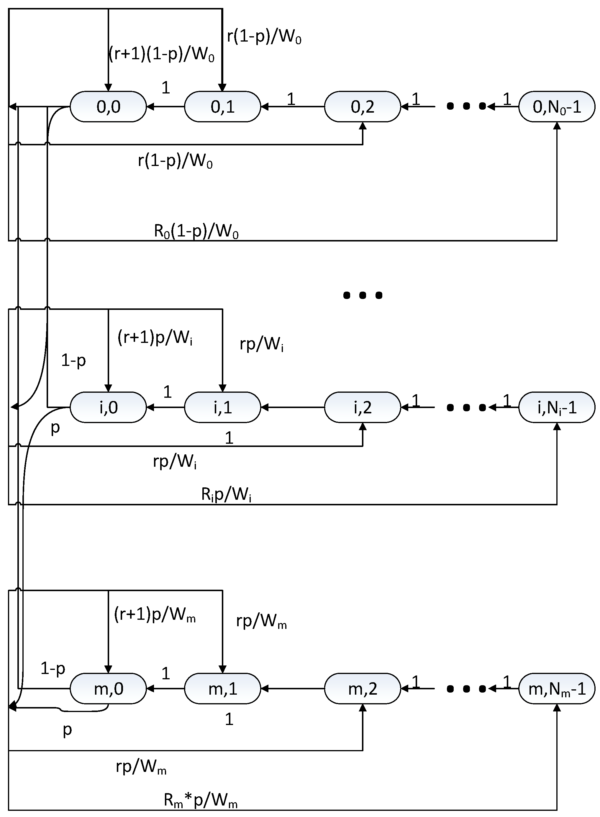
4.2. Simplified Markov Chain Model
The Markov model we have analyzed in the traditional way is slightly complicated, and we can simplify the Markov model. As can be observed from the Markov chain model shown in
Figure 8 and the equations we have derived, all
r states have similar stochastic properties except the first
r + 1 states and some last states. We call the set of states with similar properties as a stage. We try to use this number of stages as a representative residual UORA back-off value.
We use
Bi,n as a state probability of each stage where
i is the number of retransmissions as earlier and
n is the number of stages. The stage-based Markov model is described in
Figure 9, and each state indicates
Bi,n we defined. For each
i, the maximum number of stages
Ni and
Ri, number of states in
Bi,n where
n = Ni, can be described as follows.
From the total probability rule,
The simplified model we derived also provides the steady-state distribution as a function of probability if specific UORA CW sizes and RU size are given.
As in
Section 4.1, the probability of transmission can be derived as follows.
From Equations (13), (21), and (22), we can obtain specific values of the steady-state distribution and the transmission probability of the simplified model if we have specific system parameters.
4.3. Delay Analysis from Simplified Model
Assume that each state in the simplified Markov chain can be expressed as a random variable of an initial UORA back-off value. This means that if an STA gets a random UORA back-off value, the value can be mapped to an appropriate value of the stage. Simply, let us set a random variable
N as the number of UORA trigger intervals for transmission given
Rth retransmission. Now, the average overall delay can be described as
Toverall is the total delay from generating a frame to delivering it or to discarding it after M retransmissions. Tinitial is the waiting time for receiving the first UORA trigger frame after generating a frame. Tcontention is the time delay from receiving the first UORA trigger frame to successive delivery or to Mth retransmission failure. Because the time includes UORA back-off delays and retransmission delays, it is called contention delay in this paper.
From the simplified model, we can obtain the probability distribution of the random variable
N easily. For a given number of retransmission
j,
where
,
r is the number of RUs in the UORA trigger frame, and
Wj is the size of the UORA CW for the given retransmission index
j.
To determine the average delay, we must obtain the average number of stages for each STA.
The intervals of the UORA trigger frames can be described as a random variable as well. We use a random variable
I to represent it and describe the delay as below.
where
R is the number of retransmissions with the distribution:
The probability
p is an identical parameter we used in the Markov chain model. Not only can we control
p value to model UORA channel contention directly, but we can also set the
p value to the value we obtained from Equation (13). If we assume that W
j and
r are constant values over every
j,
will have a constant value
N from Equation (24). In this case, Equation (27) can be re-expressed as follows.
If we assume that the interval
I is deterministic and the initial frame generation time is random, Equation (30) can be expressed as
where
Ic is a constant value of the UORA trigger interval. If the interval follows an exponential distribution and the interval
I has an average value
Ip, then
The delays shown in Equations (31) and (32) are special cases as we referred. To simplify the equation, we assumed a constant size of CWs along with a constant size of RUs. If we have more complex patterns of CW size, the distribution of Nj will change and hence we need to calculate Equation (27) with appropriate calculation methods. Basically, computational software packages can calculate it easily even though Nj has a complex distribution. As a result, the delay can be calculated by using Equation (27), where (24), (25), and (28) are for the general UORA delay case.
5. Performance Analysis
To support a real-world V2X system, a reasonable data arrival rate of V2X vehicular STAs must be considered. In this work, a 10-Hz V2X uplink data frame arrival rate is assumed to analyze V2X channel access performance. In other words, each V2X vehicle generates its data frame to a V2X infrastructure STA every 100 ms. As the V2I uplink delay is the key delay factor of the NG-V2X system, we focus on the channel access delay and packet loss rate (PLR) performance of the proposed V2X-UORA channel access.
To demonstrate specific performance enhancement of the proposed V2X-UORA channel access, legacy IEEE 802.11p-based channel access simulation is also performed. The simulation is a system-level simulation and communication range is determined depending on its received signal power instead of its actual distance. Wideband operation can also be performed with a various number of channels and the wideband operation procedure follows IEEE 802.11 wideband operation rules. Conventional IEEE 802.11p system supports 2-band wideband operation by utilizing 2 contiguous 10 MHz channels and we assumed at most 4-band wideband operation can be supported in the next-generation V2X system. Each simulation was performed in a limited traffic generation time and a limited simulation time. Because we set unlimited retransmission tries, packet loss that affects the value of PLR means that the data packet has not been delivered in simulation time after it is generated. Therefore, the PLR is not the main target of our performance comparison but it is a constraint parameter which needs to be 0 value if the number user value is under user capacity threshold. The simulation time was set to five times the traffic generation time. This means that each V2X STA generates uplink data traffic during traffic generation time and then stops generating data frames for four times the traffic generation time. Conventional channel access procedures for transmitting data frames were performed during the whole simulation time in a conventional IEEE 802.11p scenario, and a V2X infrastructure STA transmits an UORA trigger frame every trigger frame interval over the whole simulation time. Simulation parameters we used are listed in
Table 1. Transmission Opportunity (TXOP) duration and frame arrival rate parameters on the list are calculated based on the corresponding specifications and OCW value for each case are determined by experimental results.
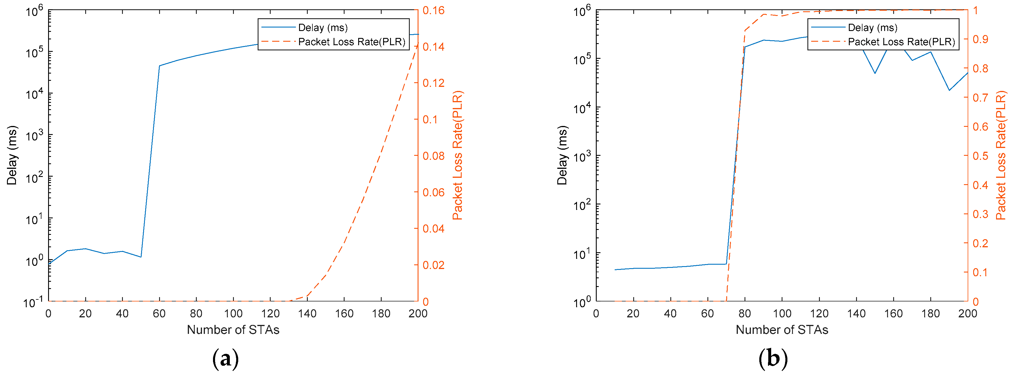
In
Figure 10, we can observe the delay and the PLR of the conventional IEEE 802.11p-based channel access procedure with 80 STAs using a single 10-MHz channel. In
Figure 10a, the delay and the PLR of a single STA in a scenario with 60 V2X STAs are shown, whereas in
Figure 10b, the delay and the PLR of a single STA in a scenario with 80 V2X STAs case are shown. It can be observed that conventional IEEE 802.11p works well in the 60 STAs case but not in the 80 STAs case. Almost all the packets are delivered in 10 ms and no packet loss is observed. Unlike in the 60 STAs case, we can observe that the delay does not have a convergence value. This means that conventional IEEE 802.11p cannot support 80 V2X STAs with a single V2X infrastructure STA in the environment we assumed. In other words, the user capacity threshold is a value between 60 and 80 for the case of the
Figure 10.
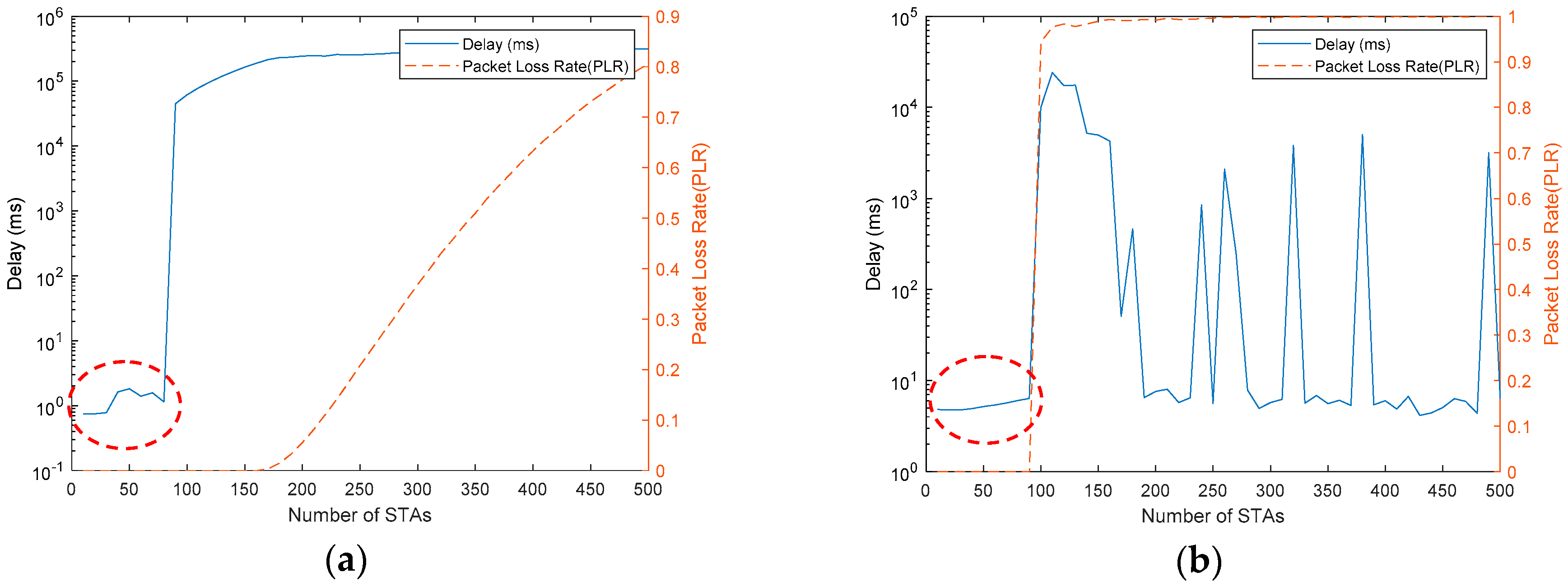
In
Figure 11a, the average delay and the PLR performance over the number of users in a single-channel conventional IEEE 802.11 scenario are shown. The X-axis represents the number of users and the delay values are log scaled. We can observe that the case of 80 users makes catastrophic delay and it is not recommended to accommodate over 80 users in the system. V2X-UORA is also simulated in a similar scenario. In a single channel, the UORA trigger frame can allocate nine RUs for uplink OFDMA transmission at most. Therefore, we use UORA trigger frames with nine RUs in the V2X-UORA channel access scenario. Similar to
Figure 11a,
Figure 11b shows the average delay and the PLR performance of STAs using a single-band transmission. The only difference between
Figure 11a and
Figure 11b is that
Figure 11b depicts the V2X-UORA channel access this paper proposes. Because OCW sizes can affect delay and PLR performance, we set the OCW size to one-tenth the number of users for adaptive OCW control.
OCW control can be performed by IEEE 802.11 beacon frames transmitted by the V2X infrastructure STA. Because an IEEE 802.11p V2X STA needs to receive the beacon frame before transmitting its frame to the V2X infrastructure STA, receiving the OCW control value included in the beacon frame is reasonable and easy to implement in NG-V2X systems. After receiving the OCW control value, each V2X can generate its own UORA back-off value for UORA channel access based on the received OCW control value. We will examine the effects of this OCW size in the last part of this section.
In this paper, we will call the largest number of users that have convergence value of delay with 0 PLR as the user capacity threshold. Therefore, we will need to examine the user capacity threshold in various scenarios. As can be observed from
Figure 11, the proposed V2X UORA enhances its user capacity threshold performance slightly. However, the specific value of performance gain could vary, depending on the specific implementation method. In some bad implementation methods, the overhead of V2X-UORA may degrade the performance gain. In some bad implementation scenarios, it is possible that the V2X-UORA channel access has a smaller user capacity than the conventional channel access case. An important thing we can observe from
Figure 11 is that the delay value in the converged delay range (dashed circles) has a relatively averaged delay value rather than having fluctuating values of delay, unlike the conventional IEEE 802.11p case.
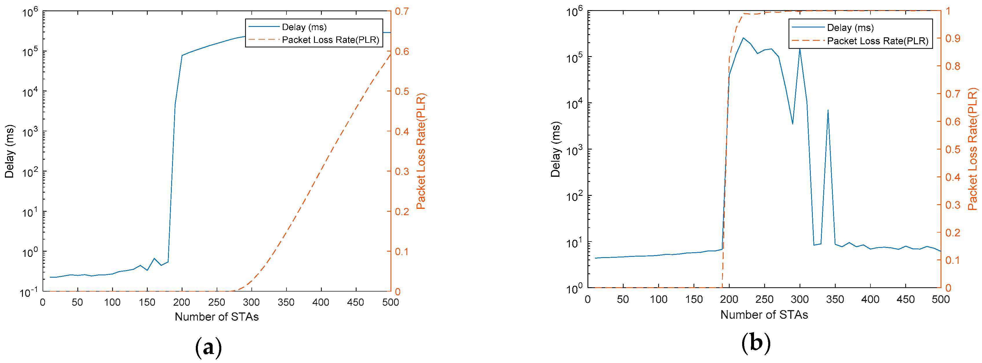
Figure 12 shows the average delay and the PLR in a two-band transmission scenario.
Figure 12a shows a conventional IEEE 802.11p channel access scenario simulated and the proposed V2X-UORA channel access applied is shown in
Figure 12b. Because a larger band allows small transmission opportunity (TXOP) duration in the conventional IEEE 802.11 case, the user capacity threshold is improved compared with the single band case. Unfortunately, V2X-UORA channel access cannot take advantage of the reduced TXOP duration from the expanded bandwidth. Instead of the reduced TXOP, V2X-UORA channel access can allocate more RUs, owing to wideband operation. According to the latest version of the IEEE 802.11ax standard, the trigger frame can allocate 18 UL OFDMA RUs at most. For a realistic simulation, 18 RUs are used in the two-band transmission case of the V2X-UORA channel access. From
Figure 12a,b, we can observe that the V2X-UORA channel access is much more scalable although it requires a slightly larger delay in the case of a small number of STAs. This means that the V2X-UORA channel access shows a much better user capacity threshold property compared to the conventional channel access case in the two-band transmission case. If the V2X system requires a quality of service (QoS) delay threshold less than 10 ms, the V2X-UORA channel access could meet the QoS requirement with the averaged delay and it uses the extended bandwidth more efficiently than the conventional wideband channel access case.
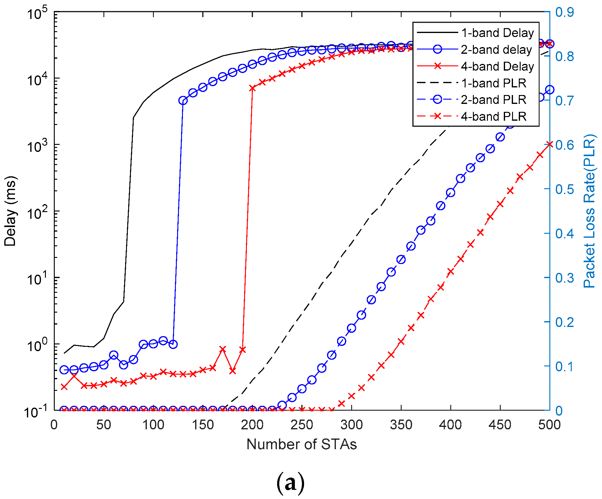
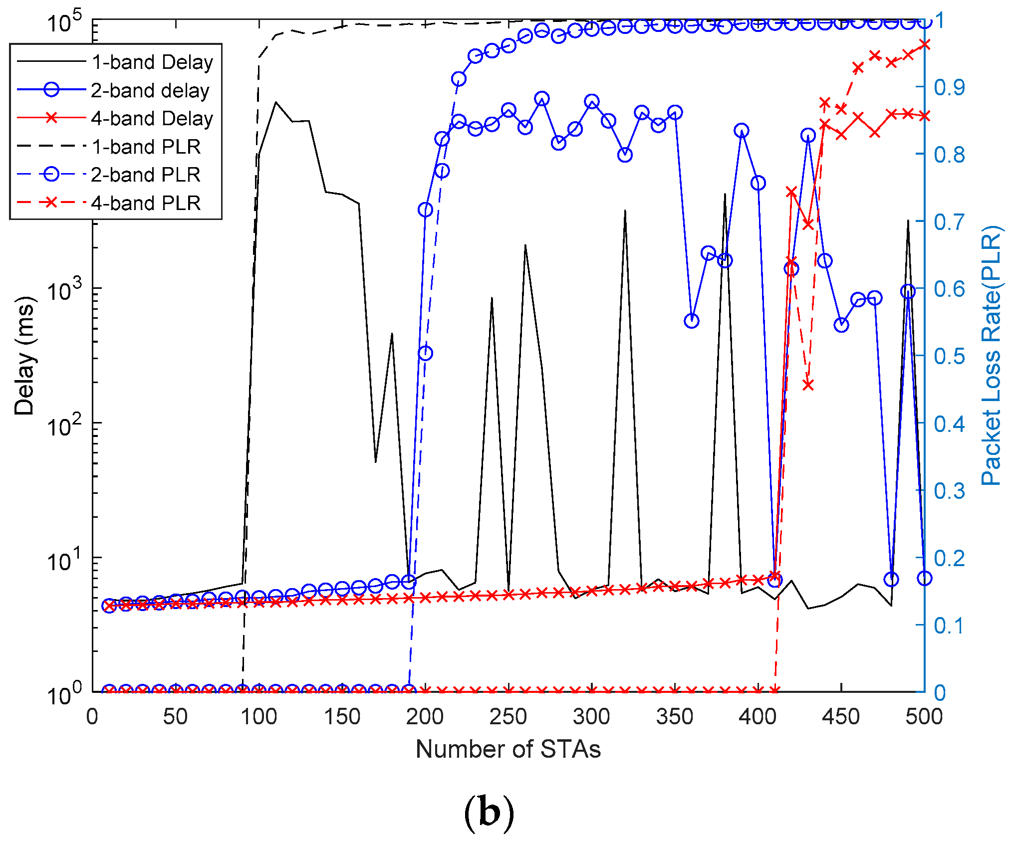
To show the tendency of wideband operation more obviously, the four-bands case is also examined. Because four-band transmission is commonly applied in recent IEEE 802.11 systems and eight-band transmission is usually implemented by 4 bands + 4 bands transmission structure, examining up to 4 bands wideband operation is reasonable.
Figure 13a shows the overall average delay and the PLR of the conventional IEEE 802.11 DCF procedure with a single, two, and four bands cases. This shows that the wideband procedure of the conventional channel access procedure can result in a shorter delay when the number of users is small, but the user capacity threshold does not increase linearly despite the number of bands increasing linearly.
Figure 13b shows the overall average delay and the PLR of the proposed V2X-UORA channel access procedure with a single, two, and four bands cases. Unlike
Figure 13a,
Figure 13b shows that using wideband transmission enhances the user capacity threshold performance more efficiently although it does not enhance delay performance and it only meets the QoS delay requirement.
In addition to the V2X-UORA performance analysis, we need to consider the extra optimization method we mentioned in the previous section. We have assumed that NG-V2X systems can have an association procedure for some special STAs including sensor STAs deployed to gather traffic information near a V2X infrastructure STA. In this case, dedicated RUs can be allocated in the UORA trigger frame for the STAs. Because of the dedicated RUs, the number of UORA RUs decreases but the dedicated RU is always occupied by the indicated STA if there are no frame errors. This means that using the dedicated RUs increases RU utilization and hence can enhance the overall delay performance as well.
Figure 14a shows that the delay and the PLR performance of the proposed V2X with and without dedicated RUs. We assumed 30 sensor STAs and the X-axis represents the extra number of V2X STAs that excludes the 30 sensor STAs. Each STA generates its data packet including traffic information every 100 ms.
Figure 14b shows how the dedicated RU with an association procedure enhances the user capacity threshold performance. Unless the dedicated RU is used, the 30 sensors are also considered as contention STAs. However, replacing only a single UORA RU in the UORA trigger frame to a dedicated RU makes the sensor STAs not participate in the UORA contention procedure. As the number of sensor STAs increases, the dedicated RU method becomes more effective.
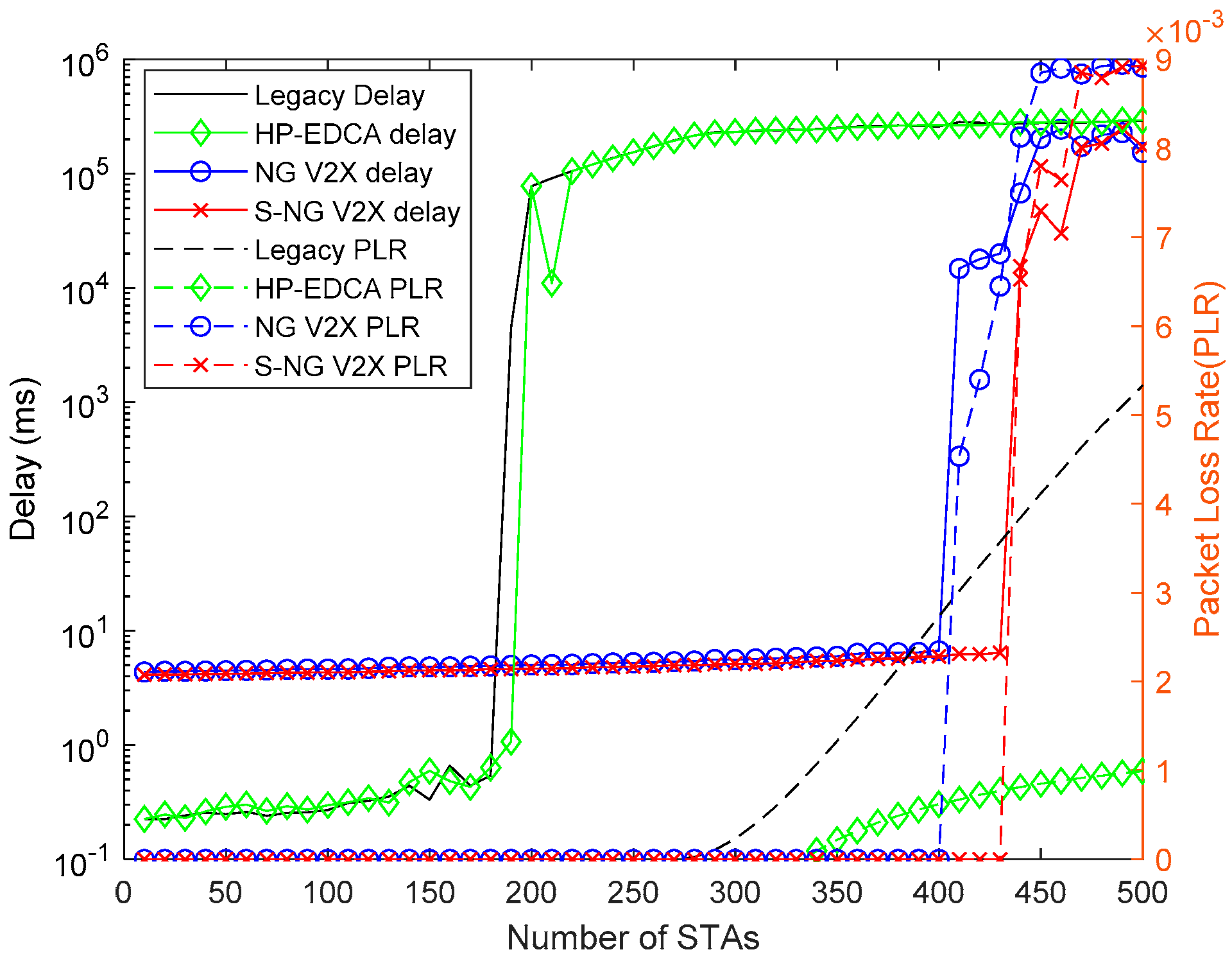
To examine the performance of the scheduled NG-V2X channel access, we compared the performance with that of legacy channel access, high-priority EDCA (HP-EDCA) and (nonscheduled) NG-V2X in
Figure 15. HP-EDCA is the IEEE 802.11p channel access procedure with high priority channel access parameters (AC_VO). Some studies have shown that applying the highest priority access category (AC_VO) to IEEE 802.11p channel access procedure improves its channel access efficiency through their analysis and simulation results [
41,
42]. As can be observed, scheduled NG-V2X shows higher user capacity performance than legacy channel access, HP-EDCA and NG-V2X cases we have stated. Although scheduled NG-V2X not only requires a more preliminary procedure including timing synchronization and RU indication but is also less adaptive than nonscheduled NG-V2X, it shows attractive user capacity performance gains.
So far, performance comparison results are focused on their performance comparison under the error-free situation for fair and easy comparison. However, in real world, there exist fading and shadowing in wireless channel and system performance can be degraded by fading and shadowing leading to a smaller coverage range than 1000 m. In order to examine the effect of fading and shadowing in wireless channel, additional simulations with fading and shadowing for 250 m coverage range and 1000 m coverage range are performed. In the simulation, more realistic simulation environment are considered. Unlike the previous results, which are with an ideal channel environment scenario using the ITU-R channel model in Urban Macro (UMa) scenario, which only considers LOS path loss without any consideration on shadowing and non-LOS (NLOS) path loss, additional simulations employ the UMa channel model with shadowing and NLOS transmission probabilities per distance considering actual environment [
43]. Channel model parameters used in the simulations are listed in
Table 2 and the result is shown in
Figure 16. The specific channel model parameters in
Table 2 are based on the recent channel model document of IEEE 802.11 working group [
44].
As shown in
Figure 16, the performance of the legacy channel access procedure is degraded dramatically for case 1. It means that 1000 m, which is an ideal coverage range of IEEE 802.11p-based system, may not be achievable in real world. Although the proposed NG-V2X shows much better performance thanks to its narrow signal bandwidth, the performance also drops significantly for case 1. For case 2, 250 m coverage range case, legacy channel access procedure shows the user capacity threshold performance that is relatively close to the ideal case performance, even though the delay increases. The proposed NG-V2X shows almost the same performance as the ideal case for case 2. It means that not only the proposed NG-V2X shows better user capacity as mentioned in the previous simulation results, but also it provides better coverage range performance for the next-generation V2X systems.
In addition to performance comparisons among channel access schemes we have proposed, we also performed the delay and PLR performance simulation under various OCW scenarios. Basically, it is easily expected that a too small OCW may cause frequent collisions and a too large OCW may cause unnecessary channel access delay. To check the exact influence of the OCW, we performed V2X-UORA channel access simulation multiple times with different OCW values and a fixed number of users.
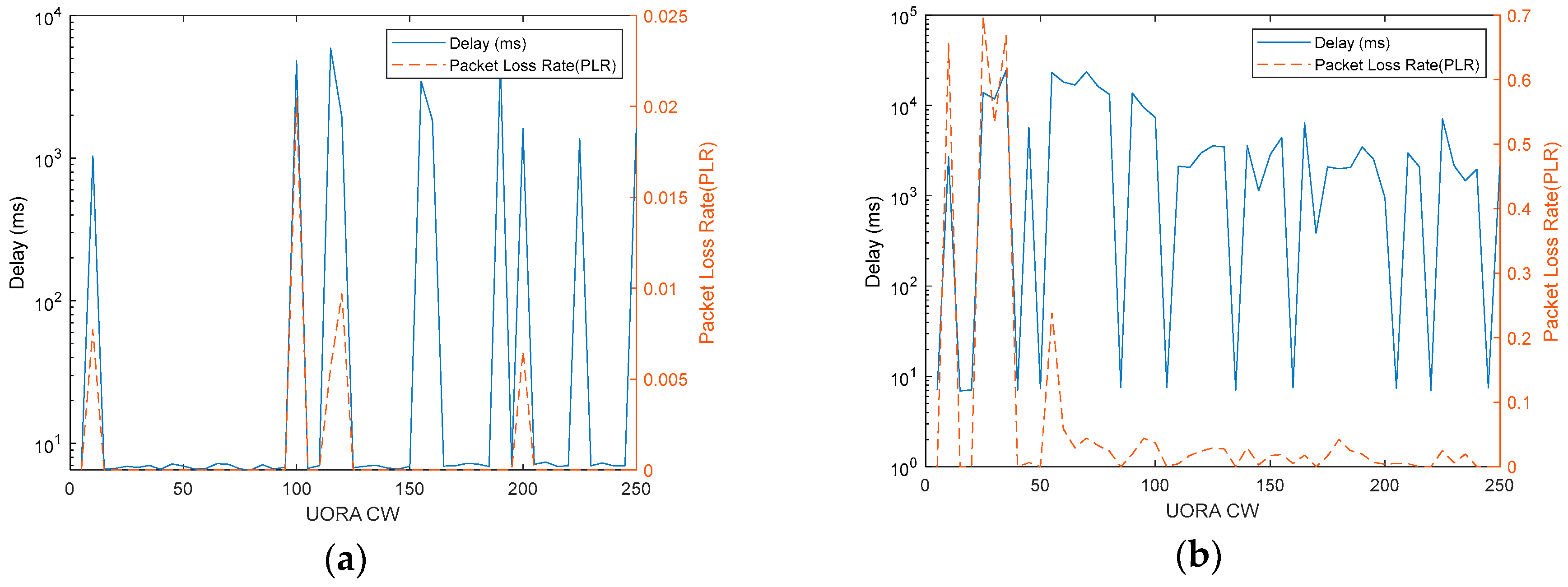
Figure 17 shows the simulation results in the case of two-band transmission. In
Figure 17a,b, we cannot observe an exact tendency unlike in the case with various number of STAs that we have analyzed. However, it is obvious that there are some sweet spot ranges for a given number of STAs, as in
Figure 17a. Therefore, if the OCW value makes the delay converged without packet loss for a given number of STAs, obtaining a specific optimal value of the OCW is not a critical issue because the sweet spot range that meets QoS requirements is wide enough. Thus, it can be interpreted as the controlling OCW not requiring extremely sensitive and immediately adaptive algorithms. Based on sensing results of sensor nodes and incoming data packets, a V2X infrastructure STA can control the OCW value with a relatively long-term decision-making algorithm.


