Article

Form-Finding Analysis of the Rail Cable Shifting System of Long-Span Suspension Bridges

School of Civil Engineering, Changsha University of Science & Technology, Changsha 410114, Hunan, China
*
Author to whom correspondence should be addressed.
Appl. Sci. 2018, 8(11), 2033; https://doi.org/10.3390/app8112033
Submission received: 26 September 2018 / Revised: 19 October 2018 / Accepted: 19 October 2018 / Published: 24 October 2018
(This article belongs to the Special Issue Structural Damage Detection and Health Monitoring)

Abstract

:
The determination of the non-loading condition of the rail cable shifting (RCS) system, which consists of the main cables, hangers, and rail cables, is the premise of girder erection for long-span suspension bridges. An analytical form-finding analysis model of the shifting system is established according to the basic assumptions of flexible cable structures. Herein, the rail cable is discretized into segmental linear cable elements and the main cable is discretized into segmental catenary elements. Moreover, the calculation and analysis equations of each member and their iterative solutions are derived by taking the elastic elongation of the sling into account. In addition, by taking the girder construction of the Aizhai suspension bridge as the engineering background, a global scale model of the RCS system is designed and manufactured. The test system and working conditions are also established. The comparison between the test results and analytical results shows the presented analytical method is correct and effective. The process is simplified in the analytical method, and the computational results and precision satisfy practical engineering requirements. In addition, the proposed method is suitable for application in the computation analysis of similar structures.

1. Introduction

Suspension bridges [1,2,3,4,5,6,7] are widely used to cross long-span barriers in engineering; their mechanical behaviors during construction have attracted the special attention of researchers [8,9,10,11,12,13,14,15]. Girder erection is the key and difficult step for the construction of the long-span suspension bridges in mountainous areas. To facilitate transportation and erection, structural types of girders are often designed as steel trusses. Mature construction methods include the deck crane construction method [16], and the cable crane construction method, among others [8,9]. Rail cable shifting (RCS) is a new, recently invented method, and it was firstly used in the successful erection of the girder of the Aizhai Bridge [17,18,19,20,21,22,23]. The erection of the 1000.5-m steel truss girder required only two and a half months [16]. With RCS, the construction period is greatly shortened, and the amount of steel used for the steel truss girder is significantly reduced. However, this technology is still new in terms of practical use, and its widespread promotion requires the accumulation of more experience. Meanwhile, knowledge and research on this technology remains to be further developed, for example to learn whether the analysis process of RCS system can be further simplified, whether the technological process can be further optimized, and whether the equipment and operations can be standardized. All of these restrict the widespread promotion and application of RCS technology.
In the presented technology, the shifting system is a double-layer flexible suspended cable system that consists of the main cables, hangers, saddles, and rail cables. With the tension of the track cable and the cable system under stress, the system will undergo obvious deformation, through which the load will be distributed according to the stiffness in the cable system [24,25,26,27,28,29,30,31,32]. For the long and flexible sling structure, deviation and elongation will appear in the process of the rail cable tensioning, and variations should not be ignored. The rail cable force during the tensioning process of the rope sling is unknown, and an implicit solution needs to be derived with respect to the deformation coordination relation of the system. These issues all these bring difficulties and complexity to the static analysis. During the process of the research and development, the finite element method is used to compute the main cable and the rail cable that are regarded as segmental catenaries, and the computational process is complicated. Moreover, the rail cable has a large pretension force, which is different from the force of the suspension cable segment obtained when only the weight force and sling force on both ends are considered.
In this paper, to simplify the form-finding [33] analysis of the RCS process under the non-loading condition, an analytical method is developed to establish the global mechanical model of the main cable, sling, and rail cable and to solve the equation, under the condition that the sling force is unknown. Here, the basic assumptions of the mechanical analysis of flexible cables are introduced and the elastic elongation of the sling is considered. The comparisons among the analytical results, the finite element results, and model test results show the presented analytical method is correct and it can be used in the computation and analysis of similar structures.

2. Mechanical Characteristics of the RCS System under the Non-Loading Condition

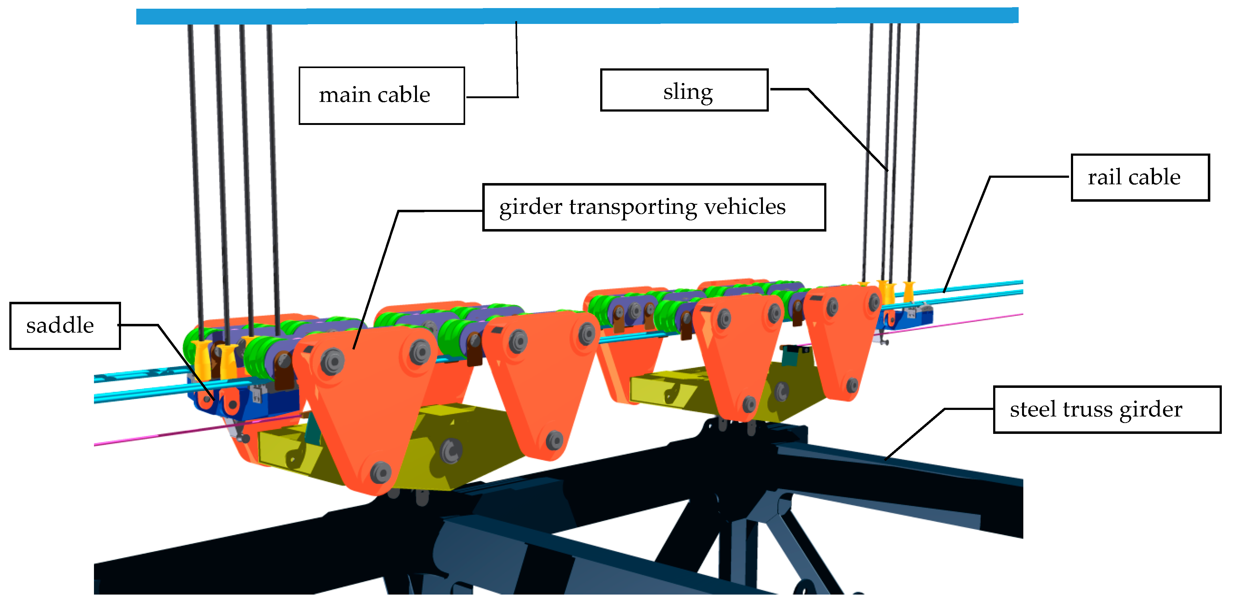
2.1. Brief Introduction to RCS Technology

In RCS (shown in Figure 1), the main cable and permanent sling are taken as the supports. A shifting cableway with a horizontal pretension force is set below the sling, which is connected with the sling through the saddle. The steel truss girder segments are separately assembled on both sides. A single segment is transported longitudinally via girder transporting vehicles along the girder transporting cableway to the position beneath the permanent sling. The steel truss girder segment is lifted by a cable crane or other hoisting equipment to exit the vehicle. Subsequently, the segments are docked and pin-connected to the sling. A symmetrical construction segment by segment then is performed from the mid-span to the two sides until the full bridge is connected.
The technology allows for the transportation of the entire stiffening girder segment, reduces the aerial work of the girder segment, shortens the construction period, reduces the construction costs, improves the construction quality and safety, and provides an advanced, economical, and highly efficient construction for the extra-long-span suspension bridge in mountainous areas. A difficult problem in the construction of the stiffening girder for the extra-long-span suspension bridge in mountainous areas is solved. This method is a major breakthrough for the construction of long-span suspension bridges in mountainous areas. Additionally, construction machines and tools are conventional, and are easy to operate and control. Moreover, it is also suitable for the girder construction of the half-through and the through arch bridges, and thus involves great adaptability and promotion value.

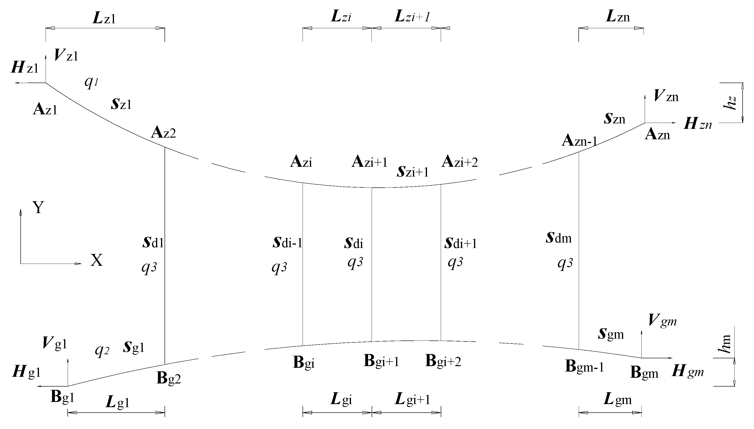
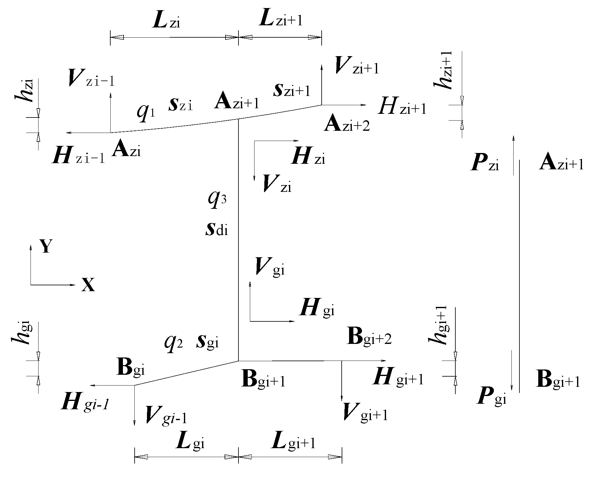
2.2. Mechanical Model of the RCS System under Non-Loading Condition

During the computation of the conventional suspension bridge construction process, the parameters of main cable are usually solved by the segmental catenary method. The sling force is determined from the completed bridge state, with backward disassembly to the cable finish state. The internal force, line shape, unstressed cable length, and sling length of the unloaded cable can be directly solved through iteration [34]. In the computation and analysis of conventional double-layer cable systems and cable dome structures, the hanger is often considered as being of rigid handling, or it is assumed to have infinite sling stiffness to ensure that the vertical displacements of the load-bearing cable and the stabilization cable are the same. This is inconsistent with the actual situation. In the finite element analysis of single-layer flexible cables, the two-node straight element, the two-node curve element [35], and the multi-node isoparametric element [36], among others, are usually used. Although there are certain limitations and deviations in the computation accuracy, computational efficiency, and applicable range of each element, the computational results in respective adaptive range can reach high accuracy and can be applied to engineering practice [37].
To simplify the form-finding analysis of the RCS process under the non-loading condition, the analytical method is used to establish the global mechanical model of the main cable, sling, and rail cable and to solve the equation, under the condition that the sling force is unknown. The basic assumptions of the mechanical analysis of flexible cables are introduced and the elastic elongation of the sling is considered. The main cable segment is simulated by a segmental catenary element, and the rail cable segment is simulated by a two-node straight pole element. The analytical results are compared with the finite element results and model test results.
The non-loading condition is defined as the status after the erection of the main cable and sling, the installation of the saddle support and the rail cable, and the tensioning of the rail cable are completed. To simplify the computational model for the system under the non-loading condition, the following assumptions are introduced [34]:
(1)
The flexible cable can only be tensed but not be pressed or bent.
(2)
The stress-strain of the flexible cable is consistent with Hooke’s theorem.
(3)
The cross-sectional area before deformation is used for the calculation of the tensile stiffness of the main cable, rail cable, and sling before and after stress.
(4)
The friction between the rail cable and the saddle is ignored, and the sling does not tilt after the rail cable tension is completed.
Then, a mechanical analytical model for the shifting system under the non-loading condition is established as shown in Figure 2, where z represents the main cable, g represents the rail cable, and d represents the sling. To describe the analysis process, an inter-segmental model is extracted for analysis, as shown in Figure 3.

2.2.1. Force Analysis of the Main Cable

As shown in Figure 3, the main cable segment is discretized into two segments: Azi-Azi+1 and Azi+1-Azi+2 under the non-loading condition. In addition, the corresponding segmental catenary element equations [34] can be established and solved to obtain lzi, hzi, lzi+1, hzi+1, Szi:
l z i = H z i s z i E 1 A 1 H z i q 1 { ln [ V z i + H z i 2 + V z i 2 ] ln [ V z i q 1 s z i + H z i 2 + ( V z i q 1 s z i ) 2 ] }
h z i = q 1 s z i 2 2 V z i s z i 2 E 1 A 1 1 q 1 [ H z i 2 + V z i 2 H z i 2 + ( V z i q 1 s z i ) 2 ]
l z i = X z i X z i 1
h z i = Y z i Y z i 1
where E1 and A1 are elastic modulus and cross-sectional area of the main cable, respectively; q1 is the self weight per unit length of the main cable; Szi is the segmental cable length after the sling installed to the unloaded cable; and i = 1~n. Other parameters are shown in Figure 2.
Based on the equilibrium state of Azi node and the sling, two additional equations can be established
H z i 1 = H z i
V z i = V z i 1 P z i q 1 s z i
where P z i is the force of the sling at the Azi node.

2.2.2. Force Analysis of the Rail Cable

The diameter, strength grade and type of the rail cable can be determined mainly from its stress level, supporting condition, safety factor, and climbing angle of shifting. As the support of rail cable lies on the saddle connected to the lower anchor point of the sling, the linear sag under non-loading conditions is small. In addition, due to the large pretension force of the rail cable, the influence of its self weight on the line shape of the cable segment is limited. Meanwhile, the assumption that each segment is in line after completion of the rail cable tension is made, which simplifies the force analysis of subsequent shifting process. Therefore, the rail cable can be discretized into the connection of multiple straight poles. A two-node straight pole element is used to simulate the force for the rail cable segment under the non-loading state, and an analytical diagram shown in Figure 4 is obtained. Furthermore, the internal forces of the straight cable segment can be directly obtained by solving the following static equilibrium equations and geometric equations,
l g i = H g i 1 T g i 1 S g i
h g i = V g i 1 T g i 1 S g i
Δ ( S g i ) = T g i S g i E 2 A 2
T g i = V g i 2 + H g i 2
H g i 1 = H g i
S g i = l g i 2 + h g i 2
V g i = V g i 1 P g i + q 2 s g i
l g i = X g i X g i 1
h g i = Y g i Y g i 1
where E2 and A2 are respectively the elastic modulus and cross-sectional area of the rail cable; q2 is the self-weight per unit length of the rail cable; Sgi is the cable length of the rail cable segment; Pgi is the sling force increment; and i = 1~m. Other parameters are shown in Figure 4.

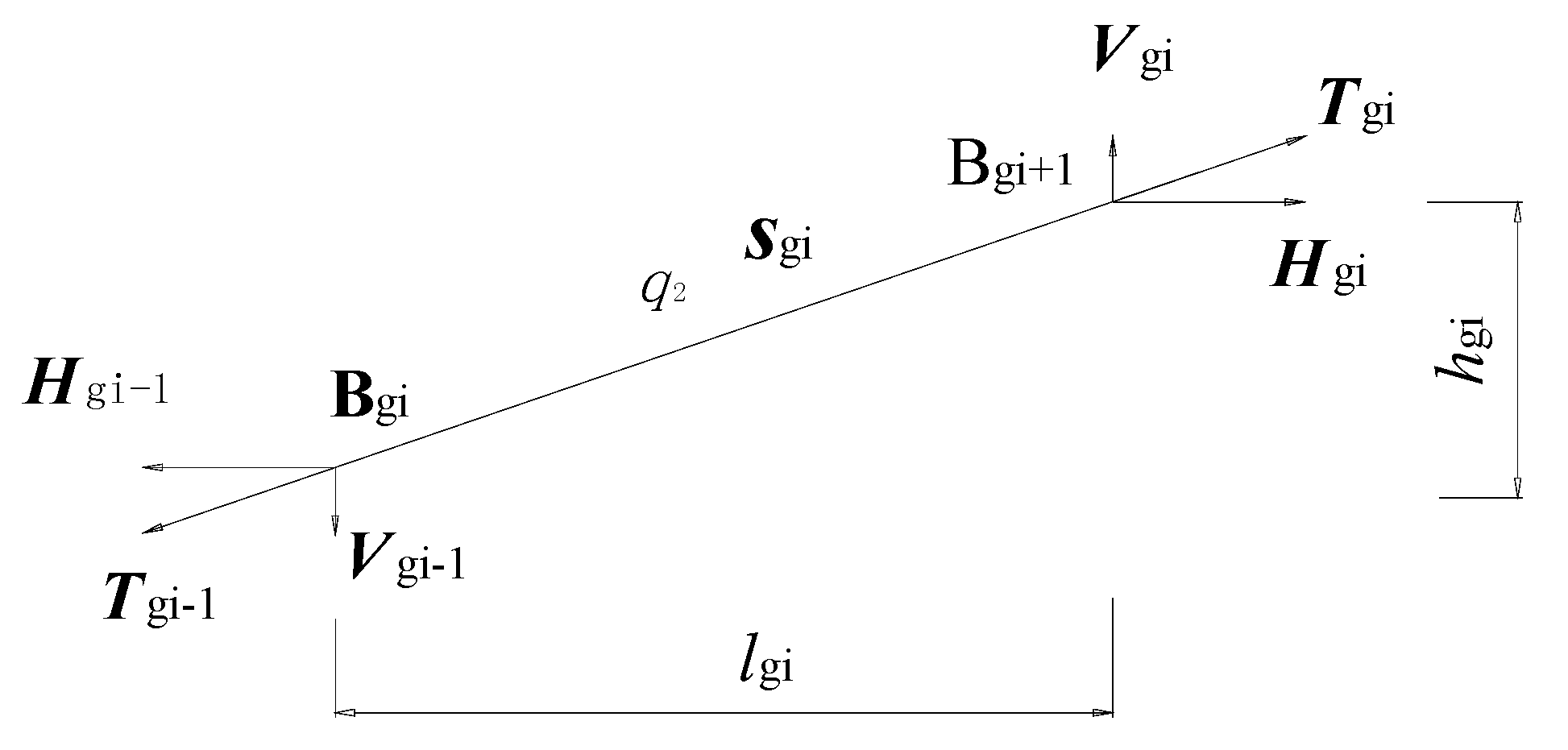
2.2.3. Force Analysis of the Sling

The force of sling is relatively simple. According to Assumption 4, the tilting of the sling is not taken into account under the non-loading condition. In an actual construction, a secondary adjustment can be applied after the pre-biasing and the tensioning of the rail cable to keep the sling being vertical after the rail cable is tensioned. The coordination relationships between the sling force and the deformation are as follows:
P z i = P g i + q 3 s d i + W ,
Y z i Y g i = P g i E 3 A 3 + s d i ,
where W is the constant weight of the saddle; E3 and A3 are the elastic modulus and cross-sectional area of the sling, respectively; q3 is the self-weight per unit length of the sling; and Sdi is the unstressed cable length of the sling. Other parameters are shown in Figure 2.

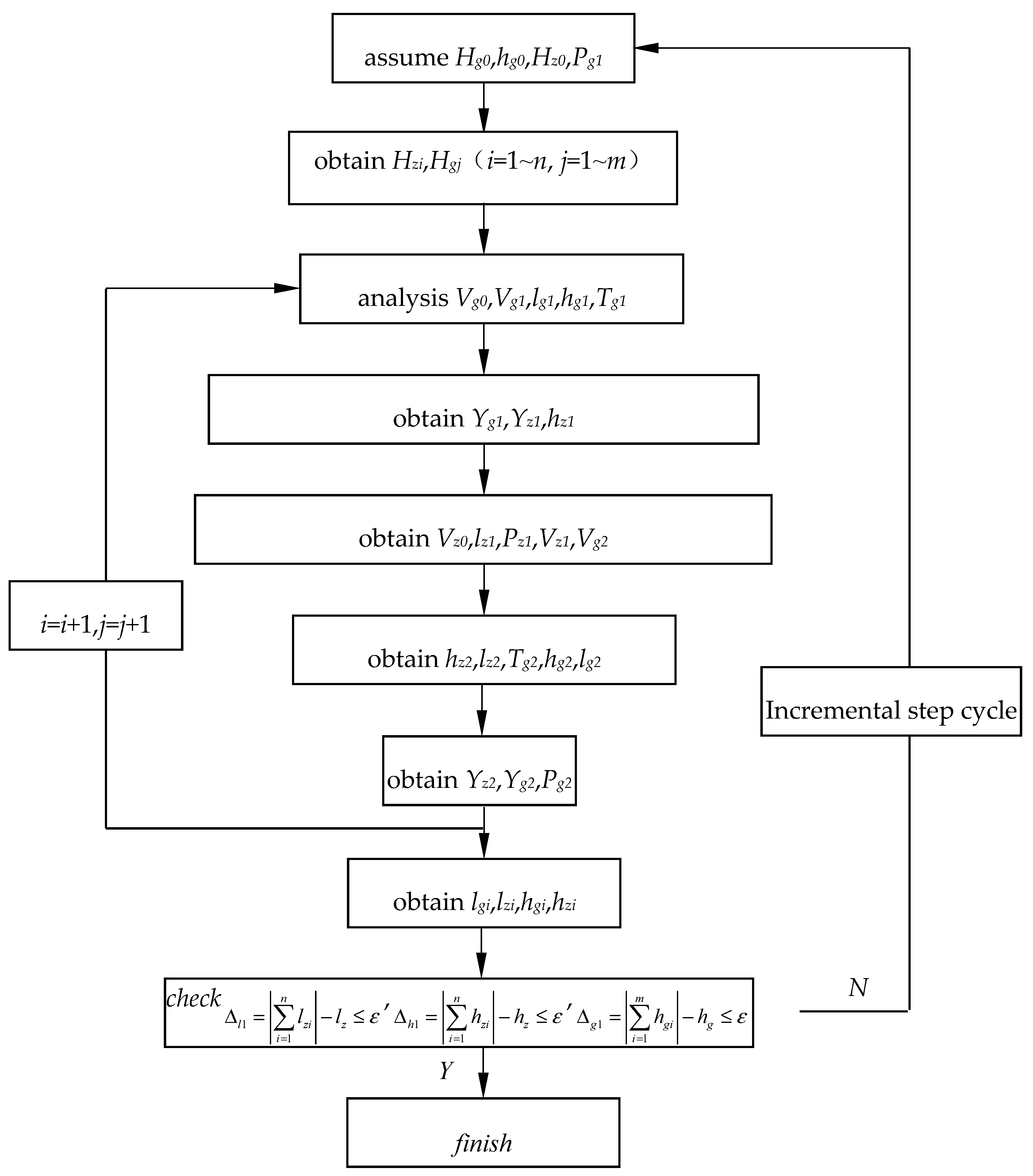
2.3. Solution Analysis of the System

Before the tensioning of the rail cable, the longitudinal position lg of the two anchorage points, the pretension force Tg0 and the unstressed cable length of the sling are known. After the installation of the sling, the cable force, line shape, cable tower distance lz, and the height difference hz can be computed according to actual conditions. On this basis, other unknown variables can be solved by an iterative method. The iterative scheme is shown below:
(1)
Assume the horizontal force Hg0 and the elevation hg0 at the left support of the rail cable; the horizontal force Hz0 at the left support of the main cable, and the increment of the cable force of the sling Pg1;
(2)
Obtain Hgi, Hzi from Equations (4) and (11);
(3)
Substitute them into Equations (10), (13), (7), (8), and (9); then Vg0, Vg1, lg1, hg1, and Tg1 are obtained;
(4)
From the coordination relation of deformation, Yg1, Yz1 and hz1 are obtained by combing with Equations (15), (17), and (4), respectively;
(5)
Substitute Yg1, Yz1 and hz1 into Equations (1) and (2); Vz0 and lz1 can then be obtained;
(6)
Substitute Vz0 and lz1 into Equations (16), (6), and (13), Pz1; Vz1 and Vg2 can then be obtained;
(7)
Substitute Pz1; Vz1 and Vg2 the results of step 6 into Equations (2), (1), (10), (7), and (8); hz2, lz2, Tg2, lg2, and hg2 can be acquired, respectively;
(8)
Substitute them into Equations (4), (15), and (17); Yz2, Yg2, and Pg2 are then obtained;
(9)
Following the similar iterative manner, all values of lgi, lzi, hgi and hzi are obtained;
(10)
Check convergence conditions Δz1 = | i = 1 n l z i | l z ε ( ε = 1.0 × 10⁻⁶ is the given error limit), Δz2 = | i = 1 n h z i | h z ε , Δg1 = | i = 1 m l g i | l g ε , and Δg2 = | i = 1 m h g i | h g 0 ε . If they are satisfied, go to the next step. If not, let Hz0 = Hz0 + Δz1/DHz, Pg1 = Pg1 + Δz2/DPg, Hg0 = Hg0 + Δg1/DHg and hg0 = hg0 + Δg2/Dhg, and return to step 1, iteratively recalculating, where DHz, DPg, DHg, and Dhg are respectively the first derivatives of Hz0, Pg1, Hg0, and hg0 [38].
Then, all the sling forces and the coordinates of each node are determined. Substituting the results into Equations (9) and (12), the unstressed cable length and the anchorage point elevation of the rail cable can be obtained. A flow diagram for the calculation is shown in Figure 5.

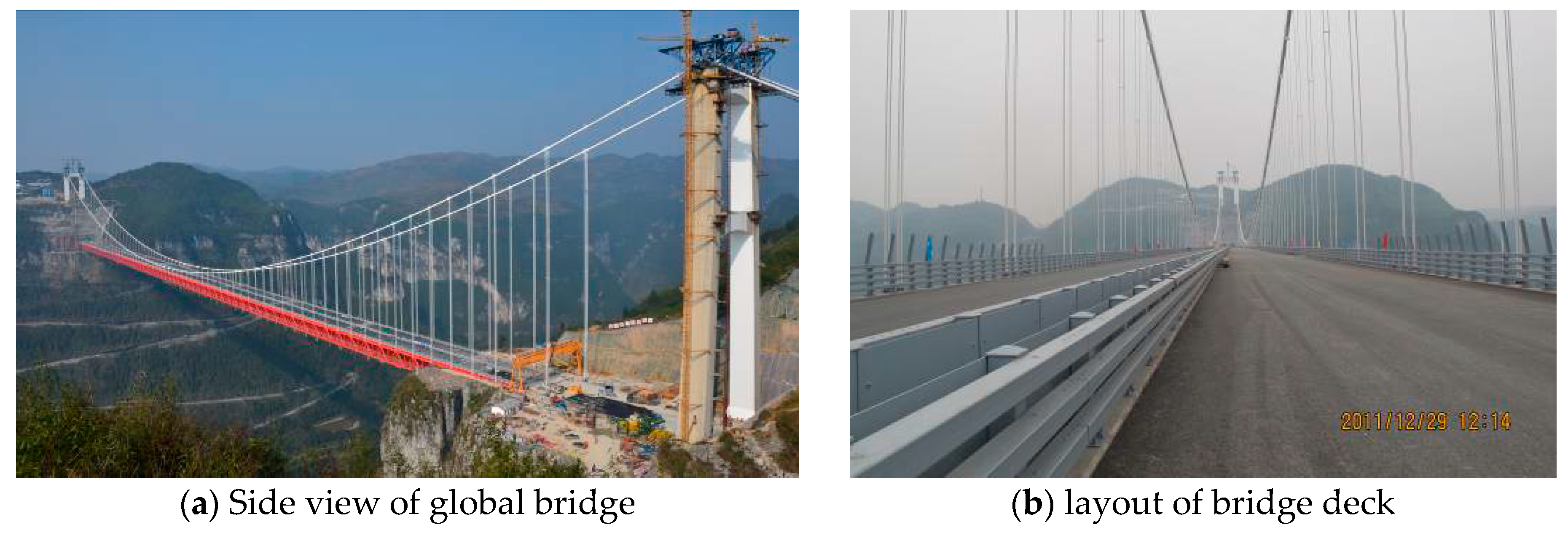
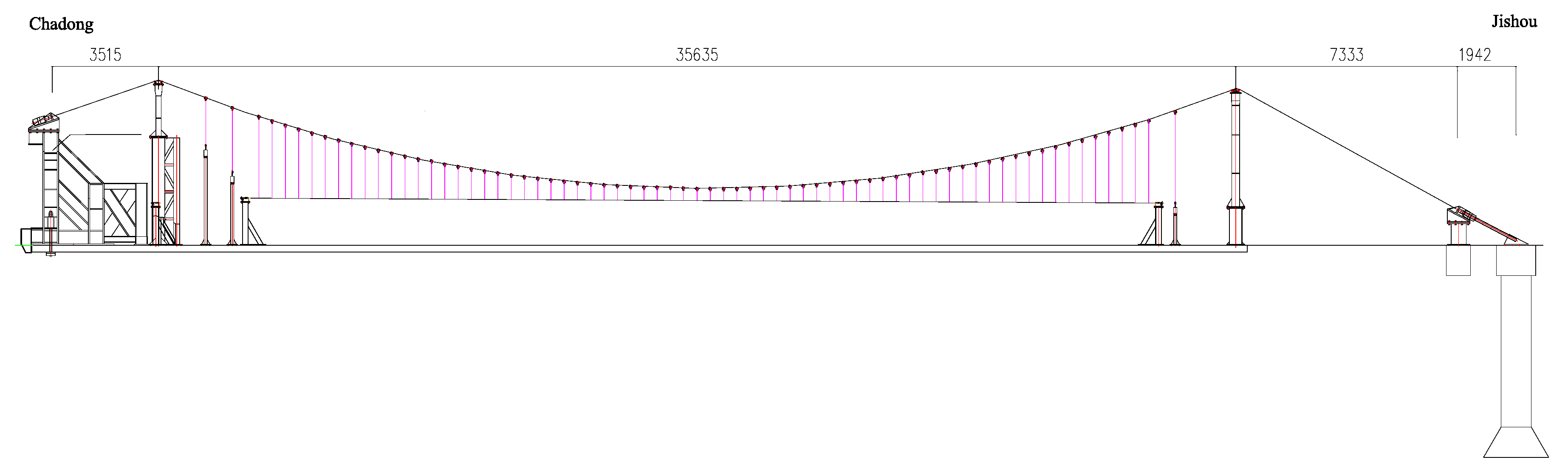
3. Global Model Test of the Moving Girder by Rail Cable

The Aizhai suspension bridge (shown in Figure 6) is a super-long steel girder suspension bridge with a main cable span of 242 + 1176 + 116 m, which built in the mountainous area of Hunan province, China. The bridge spans the u-shaped Dehang Grand Canyon, more than 500 m deep. The middle span main cable adopts the vertical span ratio of 1/9.6, the central distance of main cable is 27 m, and the plane cable layout is adopted. The bridge adopts 71 pairs of slings with the standard spacing of slings being 14.5 m. The two main cable towers adopt the reinforced concrete tower structures. The gravity anchor is used for the anchor at the Jishou side, while the tunnel anchor is used for the anchor at the Chadong side. There are 69 main girder sections for the whole bridge, which are 7.5 m in height, 14.5 m in length, 27 m in width, and 124.5 t in weight.
The rail cable launching method is the first used in the Aizhai suspension bridge to realize the horizontal movement of the girder segment. The horizontal cableway utilizes eight relatively independent 60-ZZZ-1570-type sealed steel wire ropes as rail cable. One side of the rail cable is anchored by the OVM-CPS shear force dispersing the type rock anchor system, while the other side is anchored in balance weight. The pretension force of a single rail cable is 105 t. The global laboratory experimental model was designed and manufactured with a geometrical reduced-scale ratio of 1:33. The span size of the main cable of the model is 7.333 + 35.636 + 3.515 m, its center spacing is 818 mm, and the longitudinal spacing of the sling is 439.4 mm, as shown in Figure 7.
The test model [39] mainly consists of 2 anchorage systems, 2 main cables, 68 pairs of slings and cable clamps, 3 pairs of rock anchor cables, 2 cable towers and cable towers buttresses, rail cables, rail tensioning devices, and test systems. According to the principle of stress equivalence and similar axial stiffness, the parameters of the rail cable are designed. Four 2.5-mm-diameter high-strength galvanized steel wire ropes are selected to replace rail cables. The rail cable tensioning device is designed to adjust the relative movement of the screws and nuts to achieve the tensioning of rail cables. Due to the fact that in suspended and cable-stayed bridges the cable forces are responsible for the strong variations in the static and dynamic performance of the system [40], a pressure sensor is used to monitor the changes of their cable forces in real time.
On the basis of the global model test design, the finite element software MIDAS Civil is used to establish the full bridge numerical modeling on the initial state. In the test process, the no-load stage of the cable is ensured to be consistent with the finite element analysis model by adjusting the no-load stage of the test model. After the cable clamps, slings and saddles are installed, four rail cables are tensioned, and the slings are in a vertical working condition. Then, the main cable force and line shape, rock anchor cable force, rail cable line shape, and sling cable under the tension working condition are tested to find out the changes.
The detailed contents of the MIDAS Civil modeling of the bridge are as follows. Firstly, the towers on both sides are simulated by using variable section beam element. Secondly, the main cable adopts the simulation of segmental catenary cable element, the cable clip is taken as the segmented node, the main cable between each adjacent node adopts the simulation of one catenary cable element, each sling adopts the simulation of one two-node direct cable element, and the sling connects with the main beam through the simulation of the beam element. Thirdly, the track rope is simulated by segmental straight cable element, and the saddle is taken as the segmentation node. The main cable between each adjacent node is simulated by one catenary cable element. Fourthly, the supporting rail rope of the sling saddle is connected with the sling, and its function is not considered in the model, only the load is added to the sling. Fifthly, the shear point of the main cable and the saddle is simulated with a rigid arm, and the change of the shear point is simulated by changing the position of the rigid arm. Sixthly, according to the initial state data of the empty cable tested by the overall model, the state model of the empty cable is established. Analysis and calculations of the bridge are carried out for assembly, and then for inversion to the state of the empty cable. It is checked whether the initial state of empty cable is convergent, and whether the relative displacement difference of the main cable in mid-span is small enough and meets the requirements of the accuracy of the overall model test. Seventhly, the load increment method is combined with the Newton–Raphson method to solve the problem.

4. Testing Results of Model Test

After the completion of the rail cable tensioning, the finite element results, experimental results and the analytical results are compared. The responses of several representative locations are compared in Table 1, and the cable forces at the anchor points of the main cable are shown in Table 2.
From Table 1, it can be seen that the deviation of the results gained by the analytical method from measured values and finite element values in the Y direction is small, the maximum deviation values are 4.36% and 4.00%, respectively. It is shown in Table 2 that the deviation of the main cable force at the anchorage point is small, with a maximum of 2.34%. The deviations of the main cable displacement of the mid-span, the 1/4 span on the Jishou side, and the 1/4 span on the Chadong side in X-direction are relatively large, mainly due to the small deformation value in the X direction and the test system accuracy. The comparison between the test results and the analytical results shows that the presented method can be applied to the form-finding computational analysis of the RCS system under the non-loading condition, which can simplify the analysis of the RCS system. The deviations of the simplified analytical results with the finite element results and model test results are less than 5%, which validates that the proposed method can be used in engineering practice.

5. Conclusions

With the application of the basic assumptions of flexible cables, an analytical form-finding analysis model of the rail cable shifting system is proposed. The rail cable and main cable are seen as segmental linear cable elements and catenary elements, respectively. The elastic elongation of the sling is considered to determine the analytical equation of each member and the iterative solutions. Besides the experimental data of the girder construction of the Aizhai suspension bridge, the compared results verify the accuracy and effectiveness of the presented method. The main conclusions are drawn as follows.
(1)
The global mechanical analytical model for the main cable, slings, and rail cables of the RCS system under the non-loading condition is established through the theoretical derivation. The equilibrium equation established from the position after structural deformation can be used to perform the geometrical nonlinear analysis of the structural large deformation. The simplified calculation and analysis process of the RCS system achieve sufficient accuracy, which thus can be applied in engineering.
(2)
Under the condition that the initial geometric state of the RCS system is unknown, the true internal force and geometry of the rail cable can be iteratively computed by assuming the initial force or configuration of the rail cable.
(3)
The designed rail cable tensioning and testing device meets the requirements of the model test. The measured results of the main cable line shape and main cable force in the model test are in good agreement with the theoretical results.

Author Contributions

Q.P.: Conceptualization, Data curation, Formal analysis; D.Y.: Funding Acquisition; Z.Y.: Software, Writing-Review and Editing.

Funding

The National Natural Science Foundation of China (Grant no. 51678069); the Key Discipline Fund Project of Civil Engineering of Changsha University of Sciences and Technology (Grant no. 15KB03).

Acknowledgments

The model test of Aizhai suspension bridge is performed in the Changsha University of Science and Technology, the workplace supported by the key laboratory for safety control of bridge engineering, ministry of education oh Hunan province is acknowledged.

Conflicts of Interest

The authors declared that they have no conflicts of interest to this work.

Glossary

A1cross-sectional area of the main cable
A2cross-sectional area of the rail cable
A3cross-sectional area of the sling
Azinode locations of main cable segment
E1elastic modulus of the main cable
E2elastic modulus of the rail cable
E3elastic modulus of the sling
Hg0horizontal force pretension force of the rail cable at the left support
hg0elevation at the left support of the rail cable
hg1vertical height between left anchorage points of rail cable and node Ag2
hiheight difference of cable tower
Hz0horizontal force at the left support of the main cable
hz1height difference between the top of left cable tower and node Az2
hzivertical length of main cable segment
lglongitudinal position of the two anchorage points
lg1horizontal length between left anchorage points of rail cable and node Ag2
lzcable tower distance
lzihorizontal length of main cable segment
Pg1increment of the cable force of the sling
Pgisling force increment
Pziforce of the sling at Azi node
q1self-weight per unit length of the main cable
q2self-weight per unit length of the rail cable
q3self-weight per unit length of the sling
Sdiunstressed cable length of the sling
Sgicable length of the rail cable segment
Szisegmental cable length after sling installed to unloaded cable
Tg0pretension force of the rail cable at the left support
Tg1vertical force at the left support of the rail cable
Vg0vertical force pretension force of the rail cable at the left support
Vg1vertical force between left anchorage points of rail cable and node Ag2
Wconstant weight of the saddle
Yg1vertical displacement between left anchorage points of rail cable and node Ag2
Yz1vertical displacement between the top of left cable tower and node Az2
Δg1convergence condition
Δg2convergence condition
Δz1convergence condition
Δz2convergence condition
εgiven error limit

References

  1. Xu, Y.; Øiseth, O.; Moan, T. Time domain simulations of wind- and wave-induced load effects on a three-span suspension bridge with two floating pylons. Mar. Struct. 2018, 58, 434–452. [Google Scholar] [CrossRef]
  2. Miyata, T.; Okauchi, I.; Shiraishi, N.; Narita, N.; Narahira, T. Preliminary design considerations for wind effects on a very long-span suspension bridge. J. Wind Eng. Ind. Aerodyn. 1988, 29, 379–388. [Google Scholar] [CrossRef]
  3. Siringoringo, D.M.; Fujino, Y. Observed Along wind Vibration of a Suspension Bridge Tower and Girder. Procedia Eng. 2011, 14, 2358–2365. [Google Scholar] [CrossRef]
  4. Wang, H.; Li, Ai.; Li, J. Progressive finite element model calibration of a long-span suspension bridge based on ambient vibration and static measurements. Eng. Struct. 2010, 32, 2546–2556. [Google Scholar] [CrossRef]
  5. Øiseth, O.; Rönnquist, A.; Sigbjörnsson, R. Simplified prediction of wind-induced response and stability limit of slender long-span suspension bridges, based on modified quasi-steady theory: A case study. J. Wind Eng. Ind. Aerodyn. 2010, 98, 730–741. [Google Scholar] [CrossRef]
  6. Erdoğan, H.; Gülal, E. The application of time series analysis to describe the dynamic movements of suspension bridges. Nonlinear Anal. Real World Appl. 2009, 10, 910–927. [Google Scholar] [CrossRef]
  7. Miyata, T.; Matsumoto, H.; Yasuda, M. Circumstances of wind-resistant design examinations for very long suspension bridge. J. Wind Eng. Ind. Aerodyn. 1992, 42, 1371–1382. [Google Scholar] [CrossRef]
  8. Fukumoto, Y. Steel bridge construction in Japan. J. Constr. Steel Res. 1989, 13, 259–267. [Google Scholar] [CrossRef]
  9. Kim, H.; Lee, M.; Chang, S. Determination of hanger installation procedure for a self-anchored suspension bridge. Eng. Struct. 2006, 28, 959–976. [Google Scholar] [CrossRef]
  10. Li, S.; An, Y.; Wang, C.; Wang, D. Experimental and numerical studies on galloping of the flat-topped main cables for the long span suspension bridge during construction. J. Wind Eng. Ind. Aerodyn. 2017, 163, 24–32. [Google Scholar] [CrossRef]
  11. Ko, J.M.; Xue, S.D.; Xu, Y.L. Modal analysis of suspension bridge deck units in erection stage. Eng. Struct. 1998, 20, 1102–1112. [Google Scholar] [CrossRef]
  12. Adanur, S.; Günaydin, M.; Altunişik, A.C.; Sevim, B. Construction stage analysis of Humber Suspension Bridge. Appl. Math. Model. 2012, 36, 5492–5505. [Google Scholar] [CrossRef]
  13. Diana, G.; Yamasaki, Y.; Larsen, A.; Rocchi, D.; Portentoso, M. Construction stages of the long span suspension Izmit Bay Bridge: Wind tunnel test assessment. J. Wind Eng. Ind. Aerodyn. 2013, 123, 300–310. [Google Scholar] [CrossRef]
  14. Yang, Y.; Zhang, L.; Ding, Q.; Ge, Y. Flutter performance and improvement for a suspension bridge with central-slotted box girder during erection. J. Wind Eng. Ind. Aerodyn. 2018, 179, 118–124. [Google Scholar] [CrossRef]
  15. Cho, T.; Kim, T.S. Probabilistic risk assessment for the construction phases of a bridge construction based on finite element analysis. Finite Elem. Anal Des. 2008, 44, 383–400. [Google Scholar] [CrossRef]
  16. Liu, G.; Peng, Y.; Zhou, P.; Tong, Y. Research on Erection Methods of Steel Stiffening Truss Girder for Baling River Bridge. J. Highw. Transp. Res. Dev. 2010, 4, 50–56. [Google Scholar] [CrossRef]
  17. Zhang, Q.; Li, Y.; Yu, M.; Hu, H.; Hu, J. Study of the rock foundation stability of the Aizhai suspension bridge over a deep canyon area in China. Eng. Geol. 2015, 198, 65–77. [Google Scholar] [CrossRef]
  18. Tang, H.; Li, Y.; Wang, Y.; Tao, Q. Aerodynamic optimization for flutter performance of steel truss stiffening girder at large angles of attack. J. Wind Eng. Ind. Aerodyn. 2017, 168, 260–270. [Google Scholar] [CrossRef]
  19. Huang, G.; Cheng, X.; Peng, L.; Li, M. Aerodynamic shape of transition curve for truncated mountainous terrain model in wind field simulation. J. Wind Eng. Ind. Aerodyn. 2018, 178, 80–90. [Google Scholar] [CrossRef]
  20. Fang, Z.; Zhang, K.; Tu, B. Experimental investigation of a bond-type anchorage system for multiple FRP tendons. Eng. Struct. 2013, 57, 364–373. [Google Scholar] [CrossRef]
  21. Yu, S.; Ou, J. Structural health monitoring and model updating of Aizhai suspension bridge. J. Aerosp. Eng. 2016, 30, B4016009. [Google Scholar] [CrossRef]
  22. Jianhua, H.; Ruili, S. Technical innovations of the Aizhai Bridge in China. J. Bridge Eng. 2014, 19, 04014028. [Google Scholar] [CrossRef]
  23. Han, Y.; Li, K.; He, X.; Chen, S.; Xue, F. Stress analysis of a long-span steel-truss suspension bridge under combined action of random traffic and wind loads. J. Aerosp. Eng. 2018, 31, 04018021. [Google Scholar] [CrossRef]
  24. Shen, R.; Yan, Y.; Tang, M.; Zhang, N. Design and Installation of Full-Scale Sectional Model for Testing of Rail Cable Launching Method. Bridge Constr. 2013, 1, 005. (In Chinese) [Google Scholar]
  25. Huang, J.Z.; Li, D.S.; Li, H.N.; Song, G.B.; Liang, Y. Damage identification of a large cable-stayed bridge with novel cointegrated Kalman filter method under changing environments. Struct. Control Health Monit. 2018, 25, e2152. [Google Scholar] [CrossRef]
  26. Zhou, P.; Liu, M.; Li, H.; Song, G. Experimental investigations on seismic control of cable-stayed bridges using shape memory alloy self-centering dampers. Struct. Control Health Monit. 2018, 25, e2180. [Google Scholar] [CrossRef]
  27. Liu, M.; Song, G.; Li, H. Non-model based semi-active vibration suppression of stay cables using Magneto-Rheological (MR) fluid damper. Smart Mater. Struct. 2007, 16, 1447–1452. [Google Scholar] [CrossRef]
  28. Liu, M.; Sethi, V.; Song, G.; Li, H. Investigation of locking force for stay cable vibration control using magnetorheological fluid damper. J. Vib. Acoust. 2008, 130, 054504. [Google Scholar] [CrossRef]
  29. Xu, Y.L.; Ko, J.M.; Yu, Z. Modal analysis of tower-cable system of Tsing Ma long suspension bridge. Eng. Struct. 1997, 19, 857–867. [Google Scholar] [CrossRef]
  30. An, X.; Gosling, P.D.; Zhou, X. Analytical structural reliability analysis of a suspended cable. Struct. Saf. 2016, 58, 20–30. [Google Scholar] [CrossRef]
  31. Huang, M.-H.; Thambiratnam, D.P.; Perera, N.J. Vibration characteristics of shallow suspension bridge with pre-tensioned cables. Eng. Struct. 2005, 27, 1220–1233. [Google Scholar] [CrossRef] [Green Version]
  32. Sun, Y.; Zhu, Ho.; Xu, D. A specific rod model based efficient analysis and design of hanger installation for self-anchored suspension bridges with 3D curved cables. Eng. Struct. 2016, 110, 184–208. [Google Scholar] [CrossRef]
  33. Huang, Y.H.; Fu, J.Y.; Gan, Q.; Wang, R.-H.; Pi, Y.-L.; Liu, A.-R. New method for identifying internal forces of hangers based on form-finding theory of suspension cable. J. Bridge Eng. 2017, 22, 04017096. [Google Scholar] [CrossRef]
  34. Ma, Q.; Ohsaki, M.; Chen, Z.; Yan, X. Step-by-step unbalanced force iteration method for cable-strut structure with irregular shape. Eng. Struct. 2018, 177, 331–344. [Google Scholar] [CrossRef]
  35. Rezaiee-Pajand, M.; Mokhtari, M.; Amir, R.M. A novel cable element for nonlinear thermo-elastic analysis. Eng. Struct. 2018, 167, 431–444. [Google Scholar] [CrossRef]
  36. Thai, S.; Kim, Na.; Lee, J.; Kang, J. Optimum design of cable nets by using genetic algorithm. Int. J. Steel Struct. 2017, 17, 1183–1198. [Google Scholar] [CrossRef]
  37. Li, F.; Wu, P. Dynamic behaviors of pretensioned cable AERORail structure. J. Cent. South Univ. 2015, 22, 2267–2276. [Google Scholar] [CrossRef]
  38. Lixin, B.A.O. Analysis of Aerobus Transportation System Static and Dynamic Behavior; Southwest Jiaotong University: Chengdu, China, 2007; pp. 21–46. (In Chinese) [Google Scholar]
  39. Jian, F. The Research on Scale Model Design of Aizhai Suspension Bridge; Changsha University of Science and Technology: Changsha, China, 2010; pp. 23–45. (In Chinese) [Google Scholar]
  40. Bedon, C.; Dilena, M.; Morassi, A. Ambient vibration testing and structural identification of a cable-stayed bridge. Meccanica 2016, 51, 2777–2796. [Google Scholar] [CrossRef] [Green Version]
Figure 1. The rail cable shifting system.
Applsci 08 02033 g001
Figure 2. Mechanical analytical model of the rail cable shifting (RCS) system under the non-loading condition.
Applsci 08 02033 g002
Figure 3. Mechanical discrete model of the RCS system under the non-loading condition.
Applsci 08 02033 g003
Figure 4. Discretization diagram for two-node straight pole element of the rail cable.
Applsci 08 02033 g004
Figure 5. The flow diagram of calculations.
Applsci 08 02033 g005
Figure 6. The schematic views of Aizhai long-span suspension bridge.
Applsci 08 02033 g006
Figure 7. The global model of the Aizhai suspension bridge (unit: mm).
Applsci 08 02033 g007
Table 1. Effects of the working condition of rail cable tensioning on the systematical line shape.
ItemsMain Cable Displacement at Mid-SpanMain Cable Displacement at 1/4 Span on the Jishou SideMain Cable Displacement at 1/4 Span on the Chadong Side
X Direction/mmY Direction/mmX Direction/mmY Direction/mmX Direction/mmY Direction/mm
Finite element solution1.428.6−0.69.03.67.7
Model test measured value1.527.5−0.58.93.57.5
Analytical calculation results1.626.3−0.68.73.77.2
Deviation of the finite element solution from the measured value (%)6.674.0020.001.122.862.67
Deviation of the analytical method from the measured value (%)6.674.3620.002.255.714.00
Note: The measured value is the average of the upstream and downstream measuring points. The value is negative when the X-direction measuring point moves to Jishou side and when the Y-direction measuring point moves to the upstream, and vice versa.
Table 2. Effects of the working condition of rail cable tensioning on the force of main cable.
Main Cable Force at the Anchor PointFinite Element Solution/kNModel Test Measured Value/kNAnalytical Results/kNDeviation of the Finite Element Solution from the Measured Value/%Deviation of the Analytical Method from the Measured Value/%
Jishou side61.759.961.33.012.34
Chadong side58.557.158.22.451.93

