Mapping Relevant Parameters for Efficient Operation of Low-Temperature Heating Systems in Nordic Single-Family Dwellings


Abstract
1. Introduction
- ○
- The thermal insulation and air tightness of building envelope should be improved.
- ○
- The thermal efficiency of existing space heating appliances should be enhanced.
- ○
- The use of renewable fuels in district heating, domestic heat pumps, condensing boilers should be increased, while at the same time improving the efficiency of these systems.
- ○
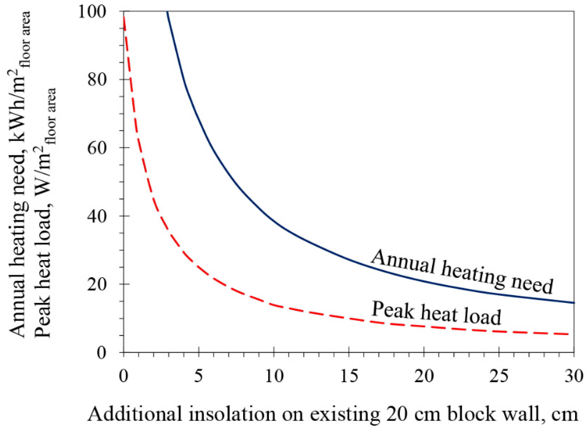
- To demonstrate the impact of building insulation on the operational mode of space heating systems.
- ○
- To demonstrate the potential of combining efficient space heating systems with a closed-loop heat pump.
- ○
- To thoroughly investigate the hydraulic pressure losses and pumping power need in heating systems operated with high water flow rates.
- ○
- To rate the influence of an increased water flow on exergy use and noise levels in the heating systems, and its impact on the efficiency of a closed-loop heat pump and CO2 emission from a single-family dwelling.
1.1. A Short Retrospective about Development of Hydronic Systems in Europe
- ○
- High-temperature systems for supply temperatures higher than 55 °C.
- ○
- Medium-temperature systems for supply temperatures between 45 °C and 55 °C.
- ○
- Low-temperature systems for supply temperatures less than 45 °C.
1.2. Reflection on Current Classification of Hydronic Systems
1.3. General Characteristics of Low-Temperature Heating Systems
- ○
- Higher pumping energy need compared to high-temperature systems [17].
- ○
- Higher heat output sensitivity due to variations in water flow rates compared to high-temperature systems [17].
- ○
- Ability to provide better or the same level of thermal comfort as traditional high-temperature systems [20].
- ○
- ○
- Uniform heat distribution, low temperature stratification, low indoor air turbulence and low radiant temperature asymmetry inside the served rooms [23].
- ○
- ○
2. Methodology
2.1. Space Heaters
2.2. Hydraulic Pressure and Power Losses in Analyzed Heating Systems
2.3. Exergy Use of Conventional Radiator
2.4. Ground-Source Heat Pump
2.5. Reference Dwelling
3. Results
3.1. Effects of Building Insulation on the Operational Mode of Space Heaters
3.2. Benefits of Low-Temperature Heating
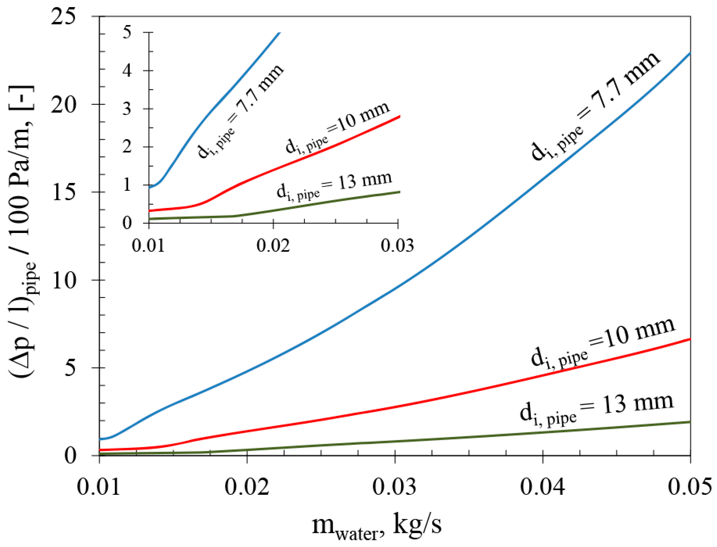
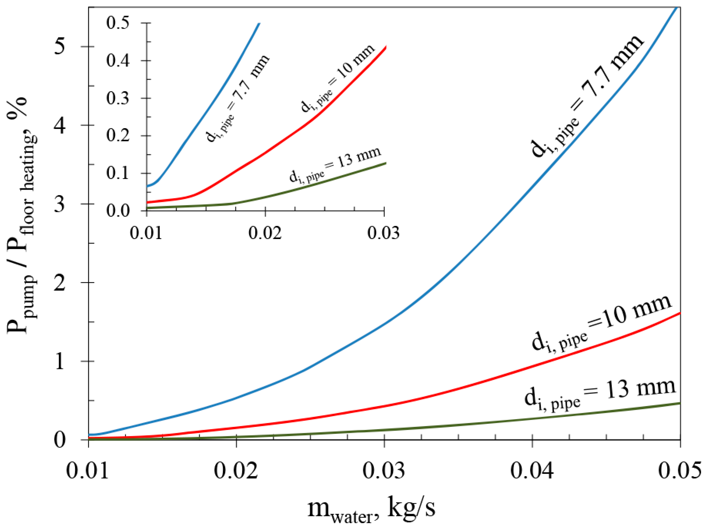
3.3. Hydraulic Pressure and Power Losses in Low-Temperature Systems
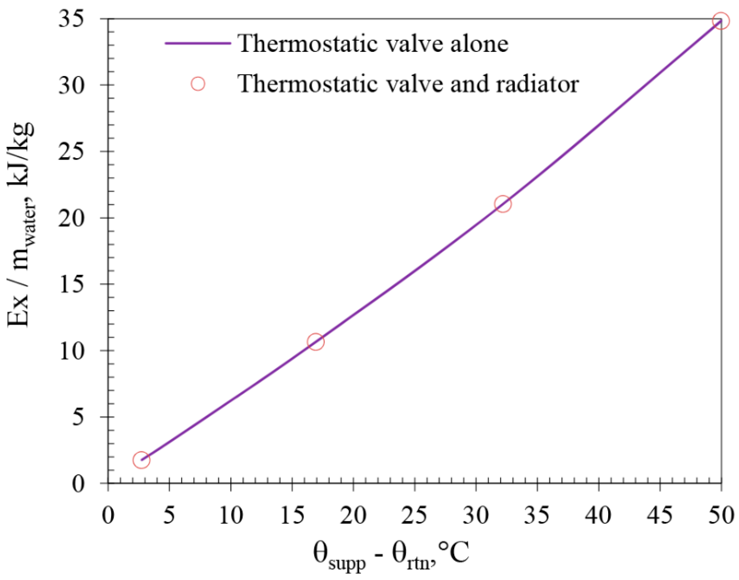
3.4. The Impact of Increased Water Flow Rate on Heat Output and Exergy Use
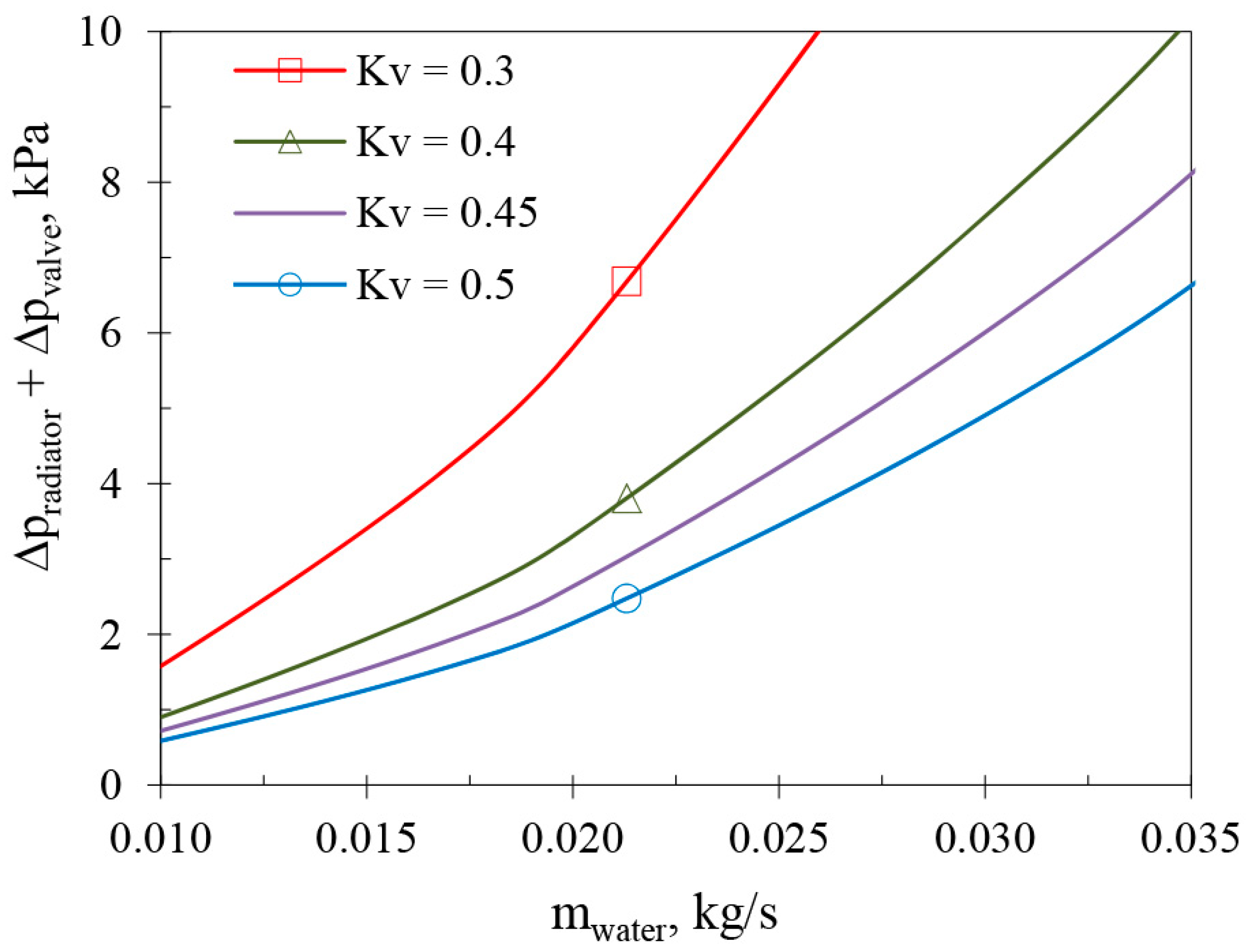
3.5. The Impact of Increased Water Flow Rate on Noise Production
3.6. Uncertainty of Presented Results
4. Discussion
5. Conclusions
- ○
- The capacity of a heating system to be operated with a water supply below 45 °C is determined to a large extent by the heating demand of a building. The size, type and efficiency of space heaters are also important factors but the heating demand is the deceive factor for efficient operation of heating systems with low-temperature water supplies.
- ○
- Well-designed and well-operated low-temperature space heaters in combination with efficient heat pumps may significantly decrease the final energy use of single-family dwellings in cold countries.
- ○
- The current guideline design values of 100 Pa/m for water-side pressure loss in distribution pipes and ≤0.01 kg/s for water flow per space heater or heating circuit are set too low and are not appropriate for low-temperature heating systems in single-family dwellings.
- ○
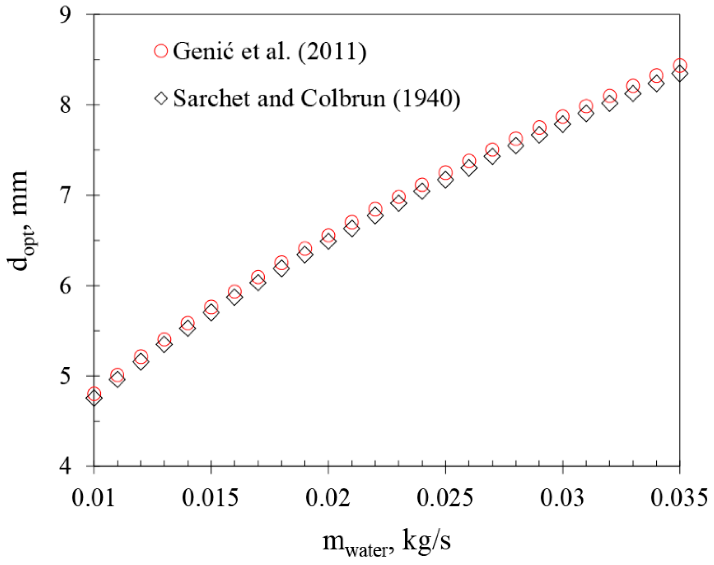
- The hydraulic pressure loss of 350 Pa per meter pipeline and water flow of 0.035 kg/s per space heater or heating circuit should be used instead of traditional values (100 Pa/m and ≤ 0.01 kg/s) for low-temperature heating systems in single-family dwellings. The pumping power need after this increase would be about 0.2–0.6% of generated heat output for distribution pipes of 10–13 mm inner-diameter.
- ○
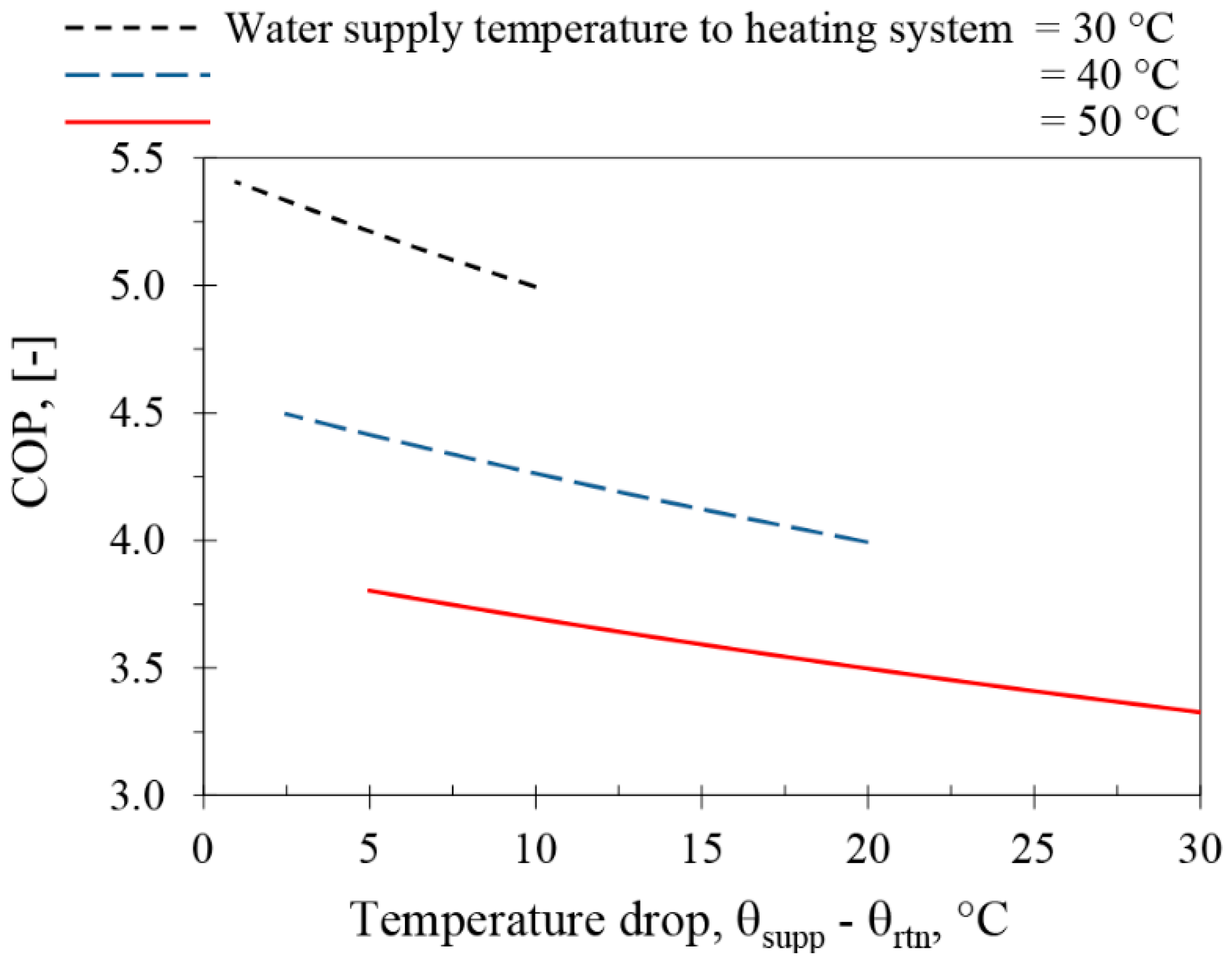
- By increasing the water flow rate from 0.01 to 0.035 kg/s per space heater, the heat output from the considered conventional radiator system increased by 25%. This increase improved the efficiency of the considered heat pump (COP) by 6%. An improvement of up to 10% could be achieved by reducing the energy needs for the domestic hot-water and circulation pumps by half.
- ○
- There is no practical justification to use water flow rates higher than 0.035 kg/s per space heater or heating circuit in heating systems supported by heat pumps in single-family dwellings.
- ○
- In order to avoid unwanted noise generation, the flow coefficient (Kv-value) of thermostatic valves should not be lower than 0.45 m3/h if a water flow of 0.035 kg/s per heating appliance is to be used.
- ○
- The hydronic heating systems that operate with small temperature drops (≤5 °C) use significantly less exergy than systems with large temperature drops. It is thus important and environmentally beneficial to create the right preconditions for heating systems to be operated with low-temperature water supplies and high water flow rates.
- ○
- Based on the conclusions listed above the following steps should be implanted to maximize the potential of low-temperature heating systems. First, the building heat loss should be minimized. Second, the thermal efficiency of space/room heaters should be maximized. Third, if possible, the temperature drop across the heating system should be held constant at about 5 °C or lower. Fourth, the heat pump connected to the low-temperature heating system should be operated with the dynamic heating curve.
Author Contributions
Funding
Acknowledgments
Conflicts of Interest
Nomenclature
| Abbreviations/Definitions | ||
| CO2 | Carbon dioxide | kg |
| COP | Coefficient of Performance (Heat output/electricity input of heat pump) | - |
| DHW | Domestic hot-water | |
| EN | European Norm/Standard | |
| GSHP | Ground Source Heat Pump | |
| HVAC | Heating, Ventilation and Air Conditioning | |
| HSPF | Heating Seasonal Performance Factor (heat output/electricity input of entire heating system including heat pump and circulators) | - |
| IPCC | Intergovernmental Panel on Climate Change | |
| Re | Reynolds number | - |
| Type 20 | Hydronic radiator with two panels | |
| Type 21 | Hydronic radiator with two panels and a single convector plate | |
| Type 22 | Hydronic radiator with two panels and two convector plates | |
| Latin letters | ||
| cp | Specific heat capacity of water (4176 in this study) | J/(kg °C) |
| d | (Based on) inner pipe diameter | m |
| Ex, | Exergy | W |
| F | Factor | - |
| f | Pipe (flow) friction factor | - |
| K | Flow coefficient of valve (valve capacity) | m3/h |
| l | Length of distribution pipes in a heating circuit | m |
| Water mass flow rate | kg/h | |
| m or | Water mass flow rate | kg/s |
| kg/s | ||
| P | Heat output or hydraulic pump power need | W |
| p | Pressure | Pa and bar |
| T | Absolute (thermodynamic) temperature | K |
| u | Water velocity in pipes | m/s |
| Volume flow rate | m3/h | |
| Greek letters | ||
| Δ | Difference | |
| ε | Absolute inner pipe roughness (1.5 × 10⁻⁶ in this study) | m |
| ζ | Radiator entrance loss coefficient (3 in this study) | - |
| η | Hydraulic efficiency of water pump | - |
| θ | Temperature | °C |
| ν | Kinematic viscosity | m2/s |
| ρ | Density | kg/m3 |
| Subscripts | ||
| comp | Compressor | |
| cond | Condenser | |
| circuit | Heating circuit | |
| el | Electricity | |
| eq. | CO2 equivalent and equivalent pipe length for components | |
| heat | Heat output of heat emitter | |
| i | First term in a sequence (first pipe line/circuit) | |
| inlet | Pipe inlet to radiator | |
| lmtd | Logarithmic mean temperature difference | |
| n | Number of pipe lines (circuits) and temperature exponent | |
| opt | Optimum | |
| pipe | Pipe | |
| pump | Pump | |
| q | Quality | |
| radiator | water-based (hydronic) radiator | |
| ref. | Reference value (1000 kg/m3 in this study) | |
| room | Room air | |
| rtn | Return water from room (space) heater | |
| supp | Supply water to room (space) heater | |
| v | Valve | |
References
- European Commission. Climate Strategies & Targets. Climate Action—European Commission, 2016. Available online: https://ec.europa.eu/clima/policies/strategies_en (accessed on 28 September 2018).
- Bonn, M.; Heitmann, N.; Götz, R.; Voßwinkel, J.S. EU Climate and Energy Policy 2030 Comments on an Evolving Framework; Centrum für Europäische Politik, cepInput: Freiburg, Germany, 2015; Available online: http://www.cep.eu/Studien/cepInput_Klima_und_Energie/cepInput_Climate_and_Energy_Policy_2020-2030.pdf (accessed on 25 November 2015).
- Bertoldi, P.; Hirl, B.; Labanca, N. Energy Efficiency Status Report 2012. Electricity Consumption and Efficiency Trends in the EU-27; Report EUR 25405 EN, JRC 69638; European Commission: Luxembourg, 2012. [Google Scholar]
- Bauermann, K.; Weber, C. Chapter 14—Heating Systems When Little Heating Is Needed. In Energy, Sustainability and the Environment; Sioshansi, F.P., Ed.; Butterworth-Heinemann: Boston, MA, USA, 2011; pp. 417–442. [Google Scholar]
- Sartori, I.; Napolitano, A.; Voss, K. Net zero energy buildings: A consistent definition framework. Energy Build. 2012, 48, 220–232. [Google Scholar] [CrossRef]
- Sesana, M.M.; Salvalai, G. Overview on life cycle methodologies and economic feasibility for nZEBs. Build. Environ. 2013, 67, 211–216. [Google Scholar] [CrossRef]
- European Commission. EU Energy in Eigures—Pocketbook 2014; Publications Office of the European Union: Luxembourg, Belgium, 2014; ISBN 978-92-79-29317-7. Available online: https://ec.europa.eu/energy/sites/ener/files/documents/2014_pocketbook.pdf (accessed on 27 September 2018).
- European Commission. EU Energy in Eigures—Pocketbook 2017; Publications Office of the European Union: Luxembourg, Belgium, 2017; ISBN 978-92-79-62312-7. Available online: https://ec.europa.eu/transport/sites/transport/files/pocketbook2017.pdf (accessed on 27 September 2018).
- International Energy Agency (IEA). CO2 Emission from Fuel Combustion Highlights; Office of Management and Administration International Energy Agency: Paris, France, 2014; Available online: https://www.iea.org/publications/freepublications/publication/CO2EmissionsFromFuelCombustionHighlights2014.pdf (accessed on 24 November 2015).
- Bredenberg, A. The Damage Done in Transportation—Which Energy Source Will Lead to the Greenest Highways? ThomasNet News. 30 April 2012. Available online: http://news.thomasnet.com/imt/2012/04/30/the-damage-done-in-transportation-which-energy-source-will-lead-to-the-greenest-highways (accessed on 2 January 2016).
- Banjac, M.; Vasiljević, B.; Gojak, M. Low Temperature Hydronic Heating System with Radiators and Geothermal Ground Source Heat Pump. FME Trans. 2007, 35, 129–134. [Google Scholar]
- Peterson, F. Compendium—Heating and Ventilation Systems. 1.4, Heating System: Conventional and Low Temperature [Kompendium—Uppvärmnings och Ventilationsteknik. 1.4, Värmesystem: Konventionella och lågtemperatur]; KTH Royal Institute of Technology: Stockholm, Sweden, 1984. (In Swedish) [Google Scholar]
- TÜV Rheinland. Radiators and Convectors According to DIN EN 442; Technical Report, DIN CERTCO, Certification Scheme DIN-Geprüft; TÜV: Rheinland, Germany, 2008. [Google Scholar]
- Thiemke, R. Effect of Increased Radiator Heating Capacity [Effekt af Forøgelse af Radiatorkapacitet]; Technical Report; Dansk Gasteknisk Center: Hørsholm, Denmark, 1998; ISBN 87-7795-129-8. (In Danish) [Google Scholar]
- Danish Energy Agency. The Danish Building Code 1995—Commercial and Multi-Storey Buildings, Paragraphs 8 and 9 [Bygningsreglement for Erhvervs- og Etagebyggeri (inkl. Tillæg 1–15), 12. Installationer, 12.2 Varme-, Varmtvands- og Køleanlæg, Stk. 8. og Stk. 9.]. Available online: http://bygningsreglementet.dk/br95_13_id206/0/42 (accessed on 26 December 2015). (In Danish).
- National Board of Housing, Building and Planning (Statens Planverks Författningssamling). SBN 1980, Swedish Building Code [SBN 1980, Svensk Byggnorm, Utgåva 2], 2nd ed.; PFS 1983:2, SBN 39:32-:33; LiberTryck: Stockholm, Sweden, 1983; ISBN 91-38-07565-2. ISSN 0348-1441. (In Swedish) [Google Scholar]
- Lindvall, N. Comparison of Two Different Adjustment Principles in a Space Heating System Consists of Hot Water Radiators (An Analysis of the Radiator Thermostatic Valves Performance and Ability to Regulate); Technical Report; Chalmers Institute of Technology (CTH), Department of Thermo and Fluid Dynamics: Gothenburg, Sweden, January 2006. (In Swedish) [Google Scholar]
- Fahlén, P. Heat Pumps in Hydronic Heating Systems—Effective Solutions for Heating and Domestic Hot Water for Conversion of Electrically Heated Single-Family Dwellings [Värmepumpar i Vattenburna Värmesystem—Effektiva Lösningar för Värme och Varmvatten för Konvertering av Eluppvärmda Småhus]; Technical Report; Chalmers University of Technology (CTH), Building Services Engineering: Gothenburg, Sweden, 2003. (In Swedish) [Google Scholar]
- Boerstra, A.; Veld, P.; Eijdems, H. The Health, Safety and Comfort Advantages of Low Temperature Heating Systems: A Literature Review. In Proceedings of the Healthy Buildings 2000, Espoo, Finland, 6–10 August 2000. [Google Scholar]
- Ovchinnikov, P.; Borodiņecs, A.; Strelets, K. Utilization potential of low temperature hydronic space heating systems: A comparative review. Build. Environ. 2017, 112, 88–98. [Google Scholar] [CrossRef]
- Babiak, J.; Olesen, B.; Petras, D. Low Temperature Heating and High Temperature Cooling, Guidebook No 7; REHVA—Federation of European Heating and Air-conditioning Associations: Brussels, Belgium, 2007. [Google Scholar]
- Fang, L.; Clausen, G.; Fanger, P.O. Impact of Temperature and Humidity on the Perception of Indoor Air Quality. Indoor Air 1998, 8, 80–90. [Google Scholar] [CrossRef]
- VTT Technical Research Centre of Finland. Heating and Cooling with Focus on Increased Energy Efficiency and Improved Comfort, Guidebook to IEA ECBCS Annex 37, Low Exergy Systems for Heating and Cooling of Buildings; Summary Report; VTT Research Notes 2256; VTT Technical Research Centre of Finland: Helsinki, Finland, 2004; ISBN 951-38-64-88-8. [Google Scholar]
- Frederiksen, S.; Werner, S. District Heating and Cooling, 1st ed.; Studentlitteratur: Lund, Sweden, 2013; ISBN 978-91-44-08530-2. [Google Scholar]
- Kazanci, O.B. Low Temperature Heating and High Temperature Cooling in Buildings. Ph.D. Thesis, Department of Civil Engineering, Technical University of Denmark (DTU), Lyngby, Denmark, 2016. Report R-356. [Google Scholar]
- Wang, Q.; Ploskić, A.; Holmberg, S. Retrofitting with low-temperature heating to achieve energy-demand savings and thermal comfort. Energy Build. 2015, 109, 217–229. [Google Scholar] [CrossRef]
- Gustafsson, M.; Gustafsson, M.S.; Myhren, J.A.; Bales, C.; Holmberg, S. Techno-economic analysis of energy renovation measures for a district heated multi-family house. Appl. Energy 2016, 177, 108–116. [Google Scholar] [CrossRef]
- Ploskić, A.; Holmberg, S. Performance evaluation of radiant baseboards (skirtings) for room heating—An analytical and experimental approach. Appl. Therm. Eng. 2014, 62, 382–389. [Google Scholar] [CrossRef]
- Purmo Thermopanel. Heat Output Calculator (Radiator Type: Purmo Compact). Available online: http://www.purmo.com/se/ladda-hem-filer/effektsimulering.htm (accessed on 16 May 2018). (In Swedish).
- Purmo. Heat Output Calculator (Floor Heating). Available online: http://www.purmo.com/de/produkte/flaechenheizung/planung-und-montage-planungsgrundlagen-waermeleistungen.htm (accessed on 21 December 2015). (In German).
- Churchill, S. Friction Factor Equations Spans all Fluid Flow Regimes. Chem. Eng. 1977, 84, 91–102. [Google Scholar]
- Samson. Application Notes for Valve Sizing (Sizing Examples); VDI/VDE Guideline 2173; Samson: Frankfurt, Germany, 2012. [Google Scholar]
- Schmidt, D. Design of Low Exergy Buildings—Method and a Pre-Design Tool. Int. J. Low Energy Sustain. Build. 2004, 3, 1–47. [Google Scholar]
- Hepbasli, A. Low exergy (LowEx) heating and cooling systems for sustainable buildings and societies. Renew. Sustain. Energy Rev. 2012, 16, 73–104. [Google Scholar] [CrossRef]
- Rosen, M.A.; Bulucea, C.A. Using Exergy to Understand and Improve the Efficiency of Electrical Power Technologies. Entropy 2009, 11, 820–835. [Google Scholar] [CrossRef]
- Nowacki, J.-E. Vitocalc 2010; Viessman Värmeteknik AB and KTH Royal Institute of Technology: Stockholm, Sweden, 2010. (In Swedish) [Google Scholar]
- Fahlén, P.; Erlandsson, J. Heat Pump Water Heaters—Alternative System Solutions for Hot Water and Space Heating [Tappvattenvärmning Med Värmepump—Alternativa Systemlösningar för Varmvatten och Värme]; Technical Report; Department of Energy and Environment, Building Services Engineering, Chalmers University of Technology (CTH): Gothenburg, Sweden, June 2010; ISSN 1652-6007, R2010:03. (In Swedish) [Google Scholar]
- SP Technical Research Institute of Sweden. Annual Field Measurements of Five Ground-Source Heat Pumps in Sjuhärad [Årsmätning på Fem Bergvärmeanläggningar i Sjuhärad]; Project from 16/11 2003 to 14/11 2004; Swedish Energy Agency: Eskilstuna, Sweden, 2005. [Google Scholar]
- Rekstad, J.; Meir, M.; Kristoffersen, A.R. Control and energy metering in low temperature heating systems. Energy Build. 2003, 35, 281–291. [Google Scholar] [CrossRef]
- Blomqvist, M.; Sahlin, K. Energy Statistics for One- and Two-Dwelling Buildings in 2012 [Energistatistik för Småhus 2012]; Technical Report; Swedish Energy Agency: Eskilstuna, Sweden, October 2013; ISSN 1654-7543, ES 2013:05. Available online: https://www.energimyndigheten.se/globalassets/nyheter/2013/energistatistik-i-smahus-2012.pdf (accessed on 22 December 2015). (In Swedish)
- Leibundgut, H.; Baldini, L.; Sanchez, J. Energy Systems Analysis—Energy in Buildings. A Lecture on Building Systems in 6 Modules—Part 2; Institute of Technology in Architecture, Faculty of Architecture, ETH (Eidgenössische Technische Hochschule): Zürich, Switzerland, 2010. [Google Scholar]
- Marlon, L.; Wolfgang, M.; Fish, M.N. The Evolution of Energy Efficiency Policy in Germany and the EnEV 2007. In Proceedings of the PLEA 2008—25th Conference on Passive and Low Energy Architecture, Dublin, Irland, 22–24 October 2008. [Google Scholar]
- Uponor. Floor Heating Installation in Single Rooms (Golvvärmeinstallation i Enstaka Rum); Technical Design Guidelines; Uponor: Virsbo, Sweden, 2010; 1368S 06-01-10-SP (5:110). (In Swedish) [Google Scholar]
- Wilo. Basis of Pumping Technology (Pump Theory) [Grundprinciper för Pumpteknik (Pumpteori)]; Handbook; WILO Sweden AB: Växjö, Sweden, 2008. (In Swedish) [Google Scholar]
- Thermopanel. Technical Brochure 07-2010 [Teknisk Broschyr 07-2010]; Rettig Sweden AB: Helsingborg, Sweden, 2010. [Google Scholar]
- Lundagrossisten. Compendium in Heating, Ventiation and Sanitary, Step 2 [Utbildningskompendium, VVS-Kunskap, Steg Två]; Handbook No 6; Lundagrossisten: Stockholm, Sweden, 2014. (In Swedish) [Google Scholar]
- Ploskić, A.; Holmberg, S. Low-temperature ventilation pre-heater in combination with conventional room heaters. Energy Build. 2013, 65, 248–259. [Google Scholar] [CrossRef]
- Scarpa, M.; Emmi, G.; De Carli, M. Validation of a numerical model aimed at the estimation of performance of vapor compression based heat pumps. Energy Build. 2012, 47, 411–420. [Google Scholar] [CrossRef]
- Confederation of Swedish Enterprise. Climate Compass. Available online: http://www.klimatkompassen.se/#/348257/ (accessed on 22 December 2015).
- Moody, L.; Princeton, N. Friction Factor for Pipe Flow. Trans. ASME 1944, 671–684. [Google Scholar]
- Genić, S.B.; Jaćimović, B.M.; Genić, V.B. Economic optimization of pipe diameter for complete turbulence. Energy Build. 2012, 45, 335–338. [Google Scholar] [CrossRef]
- Sarchet, B.R.; Colburn, A.P. Economic Pipe Size in the Transportation of Viscous and Nonviscous Fluids. Ind. Eng. Chem. 1940, 32, 1249–1252. [Google Scholar] [CrossRef]
- Maivel, M.; Kurnitski, J. Heating system return temperature effect on heat pump performance. Energy Build. 2015, 94, 71–79. [Google Scholar] [CrossRef]
- European Environment Agency. CO2 Emissions per kWh of Electricity and Heat Output. Available online: http://www.eea.europa.eu/data-and-maps/figures/co2-emissions-per-kwh-of (accessed on 23 December 2015).


| Supply | Return | Temperature Drop | |
|---|---|---|---|
| Hydronic Heating System | °C | °C | °C |
| High-temperature | 90 | 70 | 20 |
| Medium-temperature | 55 | 40 to 35 | 15 to 20 |
| Low-temperature | 45 | 35 to 25 | 10 to 20 |
| Very low-temperature | 35 | 25 | 10 |
| Supply | Return | Temperature Drop | Water Mass Flow | Heat Output | |
|---|---|---|---|---|---|
| Hydronic Heating System | °C | °C | °C | kg/h | W |
| High-temperature/low-flow | 75 | 23.9 | 51.1 | 9.91 | 580 |
| Medium-temperature/low-flow | 55 | 29.3 | 25.7 | 19.6 | 580 |
| Low-temperature/medium-flow | 45 | 34.6 | 10.4 | 48.6 | 580 |
| Low-temperature/high-flow | 41 | 37.8 | 3.20 | 158 | 580 |
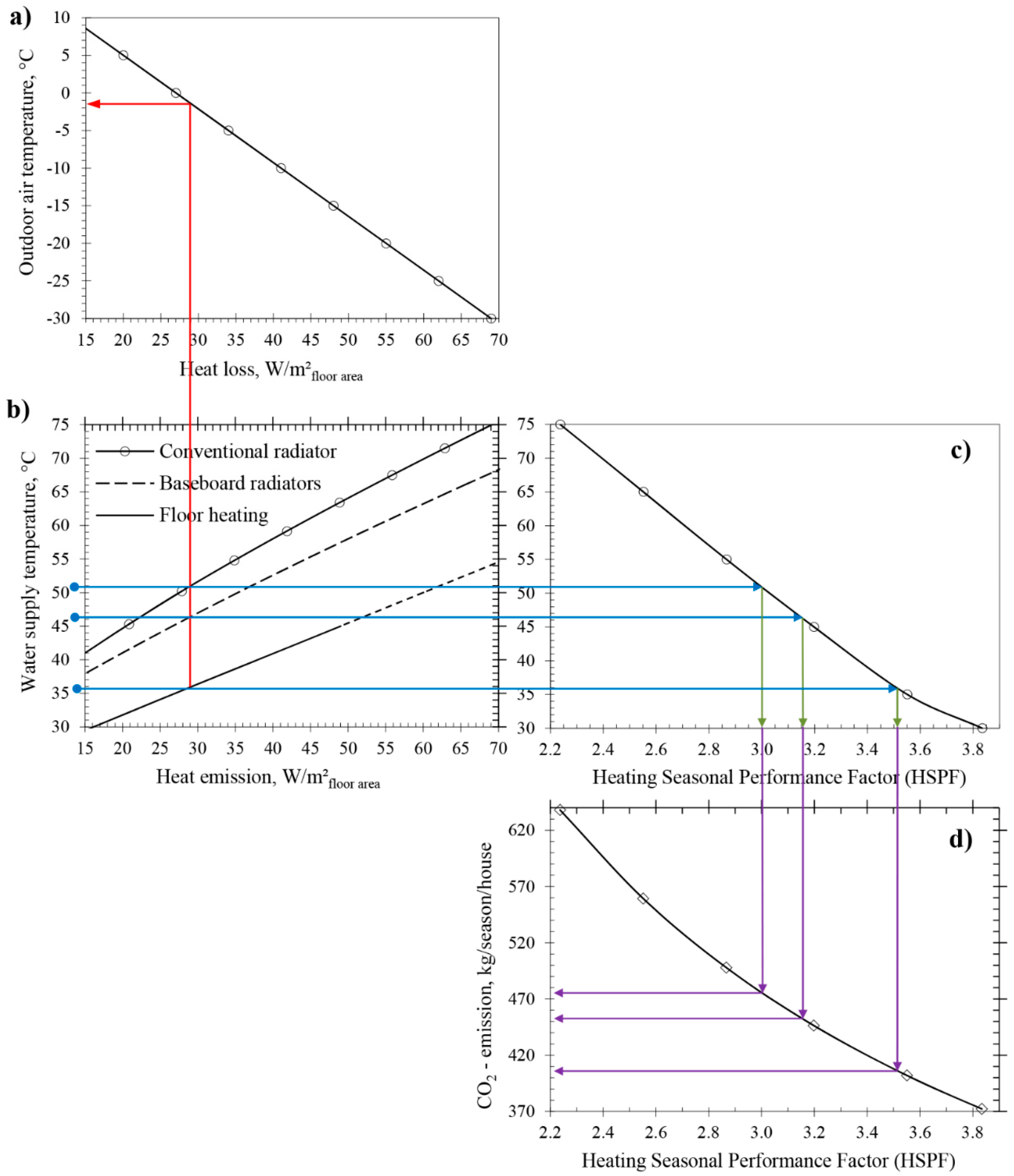
| Figure 4a | Figure 4b | Figure 4c | Figure 4d | |
| Outdoor temperature | Heating demand | Supply temperature | HSPF | CO2 |
| Decreases | Increases | Increases | Decreases | Increases |
 |  | | | |
| Figure 2 and Figure 3 | Figure 3 and Figure 4b | Figure 4c | Figure 4d | |
| Thermal insulation | Heating demand | Supply temperature | HSPF | CO2 |
| Increases | Decreases | Decreases | Increases | Decreases |
| | | | |
| Heat Emission | Pipe Length | Supply | Return | Water Flow | Pump Power Need | COP | ||
|---|---|---|---|---|---|---|---|---|
| Pheat/Afloor | lpipe/Afloor | θsupp | θrtn | /circuit | (/Afloor) × 3600 | Ppump/ | (Ppump/Pheat) × 100 | Pcond/Pcomp |
| W/m2 | m/m2 | °C | °C | kg/s | (kg/s)/m2 | W/(kg/s) | W/W | W/W |
| 29 | 3.5 | 41.0 | 27.5 | 0.01 | 1.8 | 3.2 | 5.5 x 10⁻³ | 4.1 |
| 29 | 3.5 | 35.1 | 31.1 | 0.035 | 6.3 | 28 | 0.17 | 4.8 |
| 29 | 3.5 | 34.8 | 32.0 | 0.05 | 9.0 | 54 | 0.47 | 4.9 |
© 2018 by the authors. Licensee MDPI, Basel, Switzerland. This article is an open access article distributed under the terms and conditions of the Creative Commons Attribution (CC BY) license (http://creativecommons.org/licenses/by/4.0/).
Share and Cite
Ploskić, A.; Wang, Q.; Sadrizadeh, S. Mapping Relevant Parameters for Efficient Operation of Low-Temperature Heating Systems in Nordic Single-Family Dwellings. Appl. Sci. 2018, 8, 1973. https://doi.org/10.3390/app8101973
Ploskić A, Wang Q, Sadrizadeh S. Mapping Relevant Parameters for Efficient Operation of Low-Temperature Heating Systems in Nordic Single-Family Dwellings. Applied Sciences. 2018; 8(10):1973. https://doi.org/10.3390/app8101973
Chicago/Turabian StylePloskić, Adnan, Qian Wang, and Sasan Sadrizadeh. 2018. "Mapping Relevant Parameters for Efficient Operation of Low-Temperature Heating Systems in Nordic Single-Family Dwellings" Applied Sciences 8, no. 10: 1973. https://doi.org/10.3390/app8101973
APA StylePloskić, A., Wang, Q., & Sadrizadeh, S. (2018). Mapping Relevant Parameters for Efficient Operation of Low-Temperature Heating Systems in Nordic Single-Family Dwellings. Applied Sciences, 8(10), 1973. https://doi.org/10.3390/app8101973