Article

Controlling Refraction Using Sub-Wavelength Resonators

1
Department of Mathematics and Computer Science, Auburn University at Montgomery, Montgomery, AL 36116, USA
2
Department of Mathematics, Louisiana State University, Baton Rouge, LA 70803, USA
*
Author to whom correspondence should be addressed.
Appl. Sci. 2018, 8(10), 1942; https://doi.org/10.3390/app8101942
Submission received: 10 September 2018 / Revised: 10 October 2018 / Accepted: 11 October 2018 / Published: 16 October 2018
(This article belongs to the Special Issue Photonic Metamaterials)

Abstract

:
We construct metamaterials from sub-wavelength nonmagnetic resonators and consider the refraction of incoming signals traveling from free space into the metamaterial. We show that the direction of the transmitted signal is a function of its center frequency and bandwidth. The directionality of the transmitted signal and its frequency dependence is shown to be explicitly controlled by sub-wavelength resonances that can be calculated from the geometry of the sub-wavelength scatters. We outline how to construct a medium with both positive and negative index properties across different frequency bands in the near infrared and optical regime.

1. Introduction

Metamaterials are patterned materials whose dispersive properties are controlled by their internal structure. The distinctive feature is that signal propagation within the metamaterial is governed by micro or nano resonators smaller than the smallest wavelength of the propagating signal. Familiar examples include stained glass and colloidal suspensions which derive their coloration from the plasmonic resonances of gold nanoparticles at optical frequencies, see [1]. Experimental validation of negative index metamaterials created using the negative effective magnetic permeability of split ring resonators [2] togeather with the negative effective dielectric constant from metal posts [3] proposed in [4] is given in the article of [5]. Refraction of Gaussian pulses by negative index slabs are theoretically investigated in [6]. Subsequent work has delivered several new designs using different configurations of metallic resonators and corrugated wave guides for double negative and effective magnetic behavior [7,8,9,10,11,12,13,14,15,16,17,18,19,20] in the microwave regime.
For higher frequencies in the infrared and optical range, new strategies for generating materials with double negative bulk properties rely on Mie resonances. One scheme employs coated rods made from a high dielectric core coated with a frequency dependent dielectric plasmonic or Drude type behavior at optical frequencies [21,22,23]. A second scheme employs small rods or particles made from dielectric materials with large permittivity, [24,25,26]. Alternate strategies for generating negative bulk dielectric permeability at infrared and optical frequencies use special configurations of plasmonic nanoparticles [27,28]. The list of metamaterial systems is growing and reviews of the subject can be found in [29,30]. Studies on random configuration of dielectric materials has been pursued recently in [31,32,33].
In the present work we are interested in the refraction of signals of a given center frequency and bandwidth traveling from free space into a metamaterial. We construct our metamaterial from non-magnetic sub-wavelength arrays of scatterers that exhibit both local Mie resonances as well as local plasmon resonances associated with a Drude dielectric. These resonances interlace and generate the passbands and stop bands of the metamaterial [34,35,36,37]. The resonances are shown to control the signs of the effective magnetic permeability and dielectric constant. For frequency bands where the effective properties are simultaneously positive one has a positive dispersion while one has a negative dispersion for signals over frequency bands where effective properties are simultaneously negative, see [34,35,36,37]. The Mie resonances are generated by high dielectric fibers coated with a frequency dependent dielectric. This patterned sub-wavelength heterogeneous media delivers an effective index of refraction that can either be positive or negative across different frequency bands in the near infrared and optical regime. In this paper we outline the explicit connection linking these frequency bands to the sub-wavelength geometry and associated resonances. We illustrate the resulting positive to negative index metamaterial and the associated positive to negative angle of refraction for signals transmitted into the metamaterial over different frequency bands.

2. Metamaterials and Frequency Dependent Effective Index of Refraction

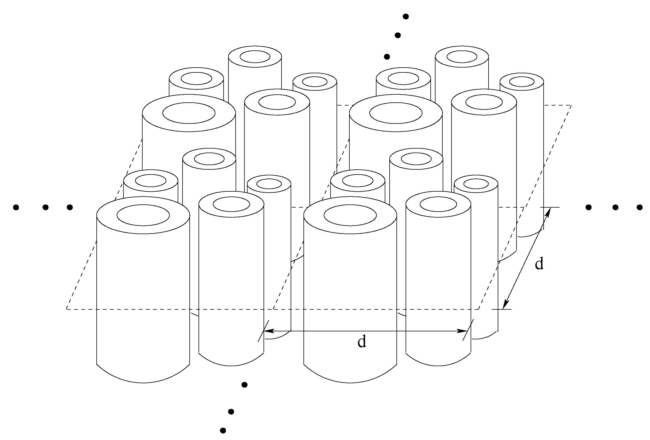
The metamaterial treated here is constructed from a two-dimensional photonic crystal made of parallel coated rods, see Figure 1. There can be one or more parallel coated rods inside the crystal period. All materials used here are nonmagnetic and have relative magnetic permeability equal to 1. We will obtain an effective magnetic response using resonant sub-wavelength geometries. The time harmonic field is TE-polarized and the magnetic field inside the crystal is parallel to the rods H = H z ( x ) exp ( i ω t ) z ^ where x = ( x , y ) in the x y -plane transverse to the rods.
The period for the crystal is d and the dielectric coefficient ϵ d ( x ) takes the values
ϵ d ( x ) = ϵ R in the rod , ϵ p in the coating , ϵ h in the host material .
The coating is a cylindrical shell of plasmonic material with dielectric constant ϵ p ( ω 2 / c 2 ) = 1 ω p 2 / c 2 ω 2 / c 2 . Here ω p is the plasma frequency associated with the coating material and c is the speed of light in vacuum. The dielectric constant of the rod is chosen according to ϵ R = ϵ r d 2 where ϵ r has units of area. The idea is to choose the dielectric permittivity of the rod to be large relative to the period size so that the corresponding Mie resonances are excited in the sub-wavelength limit. The dielectric constant of the host material is given by ϵ h = 1 .
The time harmonic magnetic field H z for the d-periodic crystal is a Bloch wave
H z = h ( x ) exp ( i k m κ ^ · x ) ,
where h is d-periodic in x , the wave number in the metamaterial is given by k m = 2 π / λ , where λ is the wavelength in metamaterial. The direction of propagation in the x y -plane is described by the unit vector κ ^ = ( κ ^ x , κ ^ y ) . The magnetic field satisfies the Helmholtz equation
· ϵ d 1 H z = ω 2 c 2 H z ,
with propagation bands described by dispersion relations relating ω / c to k m κ ^ . We examine the sub-wavelength case when d < 2 π c / ω = λ f , where λ f is the wavelength in free space. The power series approach [34,36,37] is used to find the explicit Bloch wave solution of Maxwell’s equation as a convergent multiscale power series in η = 2 π d / λ f . The η = 0 term in the expansions for dispersion relation and field deliver the“homogenized sub-wavelength” dispersion relation for plane waves inside an effectively magnetic double negative medium, see [34,36,37].
In the effective medium, the dispersion relation relating frequency ω to wave number k m is
k m = ω c n e f f ω 2 c 2 ,
where n e f f is the effective index of refraction, and this is derived rigorously in [34].
The homogenized wave is a plane B field wave:
B z H o m = B 0 e i ( k m κ ^ · x ω t ) ,
where B 0 is a constant in space and time. The homogenized B field is related to the homogenized H field by B z H o m = μ e f f ( ω 2 c 2 ) H z H o m where μ e f f is the effective magnetic permeability [36]. Here H z H o m = u ̲ 0 e i ( k m κ ^ · x ω t ) and the effective constitutive relation
H z H o m ( ω ) = u ̲ 0 e i ( k m κ ^ · x ω t ) = B z H o m ( ω ) μ e f f ( ω ) = B 0 μ e f f ( ω ) e i ( k m κ ^ · x ω t ) .
The effective dielectric permittivity is ϵ e f f ( ω 2 c 2 ) and
n e f f 2 = ϵ e f f ω 2 c 2 μ e f f ω 2 c 2 .
The explicit formulas for the frequency dependent effective magnetic permeability depend on the Dirichlet spectrum of the high contrast inclusion and the frequency dependence of the effective dielectric constant depend on the generalized electrostatic resonances (plasmon) resonances of the dielectric coating [34,36]. These formulas are presented in the next section.

3. Controlling Frequency Dependent Effective Properties and Positive and Negtive Dispersion

The frequency dependent effective magnetic permeability μ e f f and effective dielectric permittivity ϵ e f f are determined explicitly in terms of local resonances. We first rescale to a unit period cell to define effective properties. The unit cell is Y = { 0 < x < 1 ; 0 < y < 1 } . The subset of Y containing the high contrast dielectric is R, the coating containing the Drude dielectric is P and the host material occupies H. These three regions make up the unit cell Y, see Figure 2.
The Dirichlet eigenfunctions ϕ , μ
Δ ϕ ( x ) = μ ϕ ( x ) , x in R ϕ ( x ) = 0 , x on the boundary of R
with nonzero mean and associated eigenvalues of the Laplacian defined on R. The set of eigen functions and eigenvalues are denoted by ϕ n and μ n respectively for n = 1 , 2 , . The effective magnetic permeability is given by
μ e f f ω 2 c 2 = θ H + θ P + n = 1 μ n < ϕ n > R 2 μ n ω 2 c 2 ,
where · denotes the average over R, θ H and θ P are the areas occupied by regions H and P, respectively.
The generalized electrostatic resonance of the coating is the eigenfunction ψ eigenvalue γ pair solving
Δ ψ = 0 in   H , Δ ψ = 0 in P ,
with the boundary and transmission conditions
ψ | = ψ | + on the boundary of P , n ψ = 0 on the boundry of R , γ [ n ψ ] + = 1 2 ( n ψ | + n ψ | + ) on the boundary of P , ψ is Y - periodic .
Here n is the outward directed normal derivative. The generalized electrostatic eigenvalues { γ h } h = 0 lie in the open interval ( 1 2 , 1 2 ) with zero being the only accumulation point, see [34]. The eigenfunctions { ψ γ h } h = 0 form a complete orthonormal set of functions in the space of mean zero square integrable periodic functions on the set Y \ R . Similar types of electrostatic resonances are well known in the context of effective coefficients of DC two phase media [38,39].
We form the integrals
α γ h 1 = H ψ γ h d x and α γ h 2 = P ψ γ h d x .
and the frequency dependent effective dielectric constant is
ϵ e f f 1 ω 2 c 2 = θ H + ξ 0 ω 2 c 2 ϵ r ω p 2 c 2 θ P 1 2 1 2 < γ h < 1 2 ω 2 c 2 ϵ r ω p 2 c 2 | α γ h ( 1 ) | 2 + 2 ϵ r ω p 2 c 2 α γ h ( 1 ) · α γ h ( 2 ) + ϵ r ω p 2 c 2 2 ω 2 c 2 ϵ r ω p 2 c 2 | α γ h ( 2 ) | 2 ω 2 c 2 ( γ h + 1 2 ) ϵ r ω p 2 c 2 .
The index of refraction for the metamaterial is given by (6), and the dispersion relation (4). Here the the link between dispersion relation and the subwavelength geometry is explicitly given in terms of the local resonances defining the effective properties through the Formulas (8) and (12). These formulas are derived in [36,
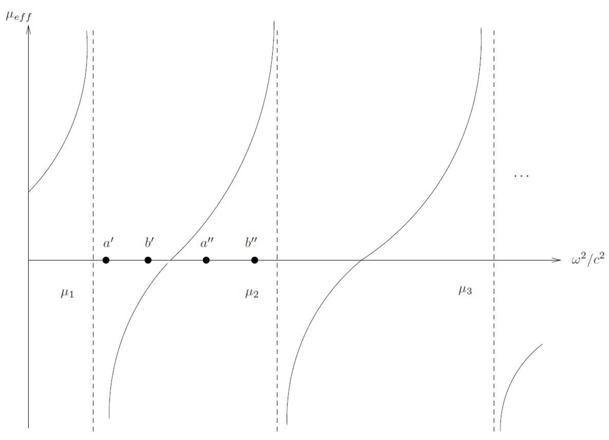
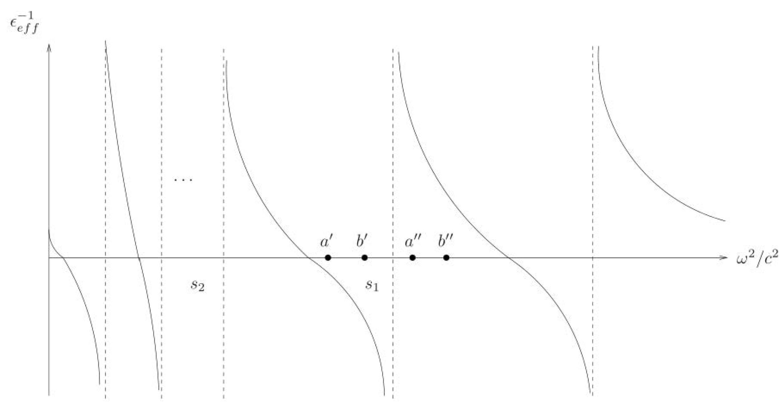
37]. It is clear that we can control the frequency dependence of μ e f f and ϵ e f f by controlling the poles and zeroes of these functions which depend on the Dirichlet resonances (7) and generalized electrostatic resonances (10) respectively. The graphs of μ e f f and ϵ e f f 1 as functions of ω 2 / c 2 are displayed in Figure 3 and Figure 4. Here the intervals a < ω 2 / c 2 < b and a < ω 2 / c 2 < b are the same in all graphs.
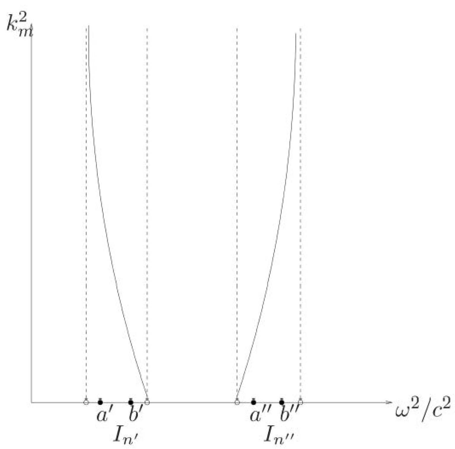
It follows that dispersion relation is also controlled by the poles and zeros of μ e f f and ϵ e f f 1 as explicitly determined through the Dirichlet spectra and generalized electrostatic resonances. The Formulas (4) and (6) show that the frequency intervals associated with pass bands and stop bands are governed by the poles and zeros of the effective magnetic permittivity and dielectric permittivity tensors. Pass bands of fixed center frequency and band width occur when the effective magnetic permittivity and dielectric permeability have the same sign. This includes frequency intervals where effective tensors are either simultaneously positive or negative. When both are positive one has positive dispersion and negative dispersion when both are negative. Bands of positive and negative dispersion are separated by stop bands, see Figure 5.
In the following sections we will choose the the high contrast core phase to be a disk centered in the period cell surrounded by an annular coating of Drude dielectric. The ratios of the disk radius and the outer diameter of the coating to the period length are fixed. We then calculate the Dirichlet and electrostatic eigenvalues to calculate a frequency dependent effective index of refraction. For the concentric Drude dielectric coating-high dielectric core geometries we can control the spectra by changing the ratio of core to coating material used, see Figure 6. Here we denote the core radius by a and the outer radius of the coating by b where these numbers are in dimensionless units relative to period length. In this context we can change the outer radius of the coating and radius of the core relative to the period size. The band width and center frequency of the negative index band and its dependence on a and b listed in Table 1. This demonstrates that we can control the frequency bands where the effective index of refraction is negative (or positive) by changing the inner and outer radii of the coating material.
These calculations highlight the frequency dependent refraction of signals composed of waves with frequencies inside different frequency bands by a free space - metamaterial system. In the following sections we demonstrate how to calculate the explicit refraction of signals passing between a free space - metamaterial interface in the time domain. We show that the same metamaterial can refract signals both positively or negatively depending only on the frequency band of the incoming signal.
In the following sections we will choose the the high contrast core phase to be a disk centered in the period cell and an annular coating. The ratios of the disk radius and the outer diameter of the coating to the period length are fixed. We then calculate Dirichlet and electrostatic eigenvalues to calculate a frequency dependent effective index of refraction. These calculations are used to highlight the frequency dependent refraction of signals composed of waves with frequencies inside different frequency bands by a free space - metamaterial system.

4. Normal Incidence on a Half Space of Metamaterial

We consider the left half space to be free space and the right half space filled with metamaterial. The interface between half spaces is parallel to the z ^ axis and the normal to the interface is taken to be the x ^ axis and the interface between half spaces is given by the x = 0 plane. We first suppose a group of waves of different frequencies propagate along the x ^ -axis, and so the H field is along the z ^ -axis and the problem reduces to one dimension.
First we consider waves inside the metamaterial. Since we have normal incidence we replace k m κ ^ by k m and x by x. We let k = ω c and write
H H o m ( k ) = B H o m ( k ) μ e f f ( c k ) = B 0 μ e f f ( c k ) e i ( k m ( k ) x k c t ) ,
Energy propagation is in the direction of increasing x so if μ e f f > 0 , ϵ e f f > 0 then n e f f > 0 while if μ e f f < 0 , ϵ e f f < 0 then n e f f < 0 , see [36,37]. On the other hand the vacuum is nonmagnetic, i.e., μ = 1 so the B and H fields are the same and
H v a c ( k ) = B 0 e i ( k x k c t ) ,
where k is the wave number in vacuum and the free space dispersion relation is k = ω c .
The wave forms inside both media are a superposition of plane waves. For each k the plane waves are of the form B 0 [ e i ( k x k c t ) R ( c k ) e i ( k x k c t ) ] for x < 0 and T ( c k ) B 0 μ e f f ( c k ) e i ( k m ( k ) x k c t ) for x > 0 . For each k the coefficients R ( c k ) and T ( c k ) are determined by the two transmission conditions
[ H 3 ] = 0 at x = 0
and
[ E 2 ] = 0 at x = 0 .
From Maxwell’s equations we have the identity inside vacuum and metamaterial
E 2 = ϵ 1 ( x ) x H 3
where
ϵ ( x ) = 1 for x < 0 , ϵ e f f ( c k ) for x > 0 .
Then the last jump condition (15) is equivalent to
[ ϵ 1 ( x ) x H 3 ] = 0 at x = 0 .
Collecting the results we give the waveforms incident reflected and transmitted across the interface x = 0 between vacuum x < 0 and effective material x > 0 .
Proposition 1.
Waveforms in vacuum and effective material.The z ^ component of the H field is the only non zero component of the H field wave form in vacuum ( x < 0 ) and is
H v a c ( k 0 , x , t ) = A ( k ) B 0 [ e i ( k x k c t ) R ( c k ) e i ( k x k c t ) ] d k ,
where the amplitude A ( k ) decribes the properties of the linear superpostion of the different waves. The z ^ component of the H field is the only nonzero component of the H field wave form in the metamaterial ( x > 0 ) and is
H e f f ( k 0 , x , t ) = A ( k ) T ( c k ) B 0 μ e f f ( c k ) e i ( k m ( k ) x k c t ) d k .
  • Here H v a c ( k 0 , x , t ) = H e f f ( k 0 , x , t ) at the interface x = 0
    The y ^ component of the E field is the only nonzero component of the E field in vacuum ( x < 0 ) and is
    E v a c ( k 0 , x , t ) = A ( k ) B 0 d d x [ e i ( k x k c t ) R ( c k ) e i ( k x k c t ) ] d k .
    The y ^ component of the E field is the only nonzero component of the E field in the metamaterial ( x > 0 ) and is
    E e f f ( k 0 , x , t ) = A ( k ) ϵ e f f ( c k ) T ( c k ) B 0 μ e f f ( c k ) d d x [ e i ( k m ( k ) x k c t ) ] d k .
  • Here E v a c ( k 0 , x , t ) = E e f f ( k 0 , x , t ) at the interface x = 0
    where
    R ( c k ) = 1 ϵ e f f ( c k ) k k m ( c k ) 1 + ϵ e f f ( c k ) k k m ( c k )
    and
    T ( c k ) = 2 μ e f f ( c k ) ϵ e f f ( c k ) k m ( c k ) k + ϵ e f f ( c k )
Now we introduce n e f f 2 ( c k ) = ϵ e f f ( c k ) μ e f f ( c k ) and k m / k = n e f f ( c k ) and we can write
R ( c k ) = 1 ϵ e f f ( c k ) n e f f ( c k ) 1 + ϵ e f f ( c k ) n e f f ( c k )
and
T ( c k ) = 2 n e f f 2 ( c k ) 1 + ϵ e f f ( c k ) n e f f ( c k )
Note that R ( c k ) < 1 if n e f f < 0 and ϵ e f f < 0 .
In our paper, we consider a signal made of a group of waves with frequencies lying inside a prescribed band of frequencies for which
A ( k ) = a 2 π e ( k k 0 ) 2 a 2 2 χ ^ ( ω )
where
χ ^ ( ω ) = 1 for ω L ω ω U , 0 otherwise .
In order to make the H-field dimensionless, we can use ω p t to denote the time change, and ω p x c the position change. Let ω ¯ = k 0 c be the center frequency. Then the transmitted wave packet (19) can be written as
H e f f = ω p a c 1 2 π e ( k c ω p k 0 c ω p ) 2 ( ω p a c ) 2 2 χ ^ ( ω / ω p ) T ( ω / ω p ) B 0 μ e f f ( ω / ω p ) e i ( k m c ω p ω p x c k c ω p ( ω p t ) ) d ( k c ω p ) = ω p a c 1 2 π e ( ω ω p ω ¯ ω p ) 2 ( ω p a c ) 2 2 χ ^ ( ω / ω p ) T ( ω / ω p ) B 0 μ e f f ( ω / ω p ) e i [ ( n e f f ω ω p ) ( ω p x c ) ( ω ω p ) ( ω p t ) ] d ( ω ω p )
Similarly the reflected wave packet is
H v a c = ω p a c 1 2 π e ( ω ω p ω ¯ ω p ) 2 ( ω p a c ) 2 2 χ ^ ( ω / ω p ) × B 0 [ e i [ ( ω ω p ) ( ω p x c ) ( ω ω p ) ( ω p t ) ] R ( ω / ω p ) e i [ ( ω ω p ) ( ω p x c ) ( ω ω p ) ( ω p t ) ] ] d ( ω ω p ) .
The incident wave packet without reflection is
H i n c = a 2 π e ( k k 0 ) 2 a 2 2 χ ^ ( ω ) B 0 e i ( k x k c t ) d k = ω p a c 1 2 π e ( ω ω p ω ¯ ω p ) 2 ( ω p a c ) 2 2 χ ^ ( ω / ω p ) B 0 e i [ ( ω ω p ) ( ω p x c ) ( ω ω p ) ( ω p t ) ]
In our example, we take ω p a c = 300 , ω L / ω p = 0.735 and ω U / ω p = 0.74 . Let the dimensionless center frequency ω ¯ ω p = 0.7375 . We use Riemann sum to approximate the integral by the sum of two rectangles.
Let J ( ω / ω p ) = e ( ω ω p ω ¯ ω p ) 2 ( ω p a c ) 2 2 e i [ ( ω ω p ) ( ω p x c ) ( ω ω p ) ( ω p t ) ] . The incident wave packet without any reflections is
H i n c = ω p a c 1 2 π χ ^ ( ω / ω p ) B 0 J ( ω / ω p ) d ( ω ω p ) = ω p a c 1 2 π 0.735 0.74 B 0 J ( ω / ω p ) d ( ω ω p ) ω p a c 1 2 π Δ ( ω ω p ) B 0 [ J ( 0.735 ) + J ( 0.74 ) ] ,
where ω p a c 1 2 π Δ ( ω ω p ) B 0 is a constant. Figure 7 is the graph for J ( 0.735 ) + J ( 0.74 ) for ω p t = 5 .
Let G ( ω / ω p ) = e ( ω ω p ω ¯ ω p ) 2 ( ω p a c ) 2 2 [ e i [ ( ω ω p ) ( ω p x c ) ( ω ω p ) ( ω p t ) ] R ( ω / ω p ) e i [ ( ω ω p ) ( ω p x c ) ( ω ω p ) ( ω p t ) ] ] . The incident wave packet with the interaction of reflection is
H v a c = ω p a c 1 2 π χ ^ ( ω / ω p ) B 0 G ( ω / ω p ) d ( ω ω p ) = ω p a c 1 2 π 0.735 0.74 B 0 G ( ω / ω p ) d ( ω ω p ) ω p a c 1 2 π Δ ( ω ω p ) B 0 [ G ( 0.735 ) + G ( 0.74 ) ] .
Figure 8 is the graph for G ( 0.735 ) + G ( 0.74 ) for ω p t = 5 which is H field in vacuum with interaction between incident and reflective waves.
Let F ( ω / ω p ) = e ( ω ω p ω ¯ ω p ) 2 ( ω p a c ) 2 2 T ( ω / ω p ) μ e f f ( ω / ω p ) e i [ ( n e f f ω ω p ) ( ω p x c ) ( ω ω p ) ( ω p t ) ] . Then we have
H e f f = ω p a c 1 2 π χ ^ ( ω / ω p ) B 0 F ( ω / ω p ) d ( ω ω p ) = ω p a c 1 2 π 0.735 0.74 B 0 F ( ω / ω p ) d ( ω ω p ) ω p a c 1 2 π Δ ( ω ω p ) B 0 [ F ( 0.735 ) + F ( 0.74 ) ] ,
where ω p a c 1 2 π Δ ( ω ω p ) B 0 is a constant. Figure 9 and Figure 10 are the graphs for F ( 0.735 ) + F ( 0.74 ) for different ω p t , i.e., the transmitted wave motion in metamaterial ( x > 0 ). Figure 9 shows transmitted wave motion from the bottom to the top for ω p t ranging from 5 to 9 in the steps of 2. It can be observed that the group velocity of the transmitted wave in metamaterial has the forward direction (the envelope moves forward). Figure 10 shows the transmitted wave motion from the bottom to the top for ω p t ranging from 5 to 7 in the steps of 1. We can see that the phase of the transmitted wave in metamaterial moves backward.
The H field at the interface between the vacuum ( x < 0 ) and effective double negative material ( x > 0 ) is shown in Figure 11. The graph shows the continuity of the magnetic field at the interface. But it is not differentiable at the interface.

5. Oblique Incidence on a Metamaterial: A Positive to Negative Index Refraction

Consider the 2D motion of the H-polarized field given by H = [ 0 , 0 , H z ] T and E = [ E x , E y , 0 ] T . In the vacuum, the third component of the incident H field is given by
H z i n = B 0 e i ( k κ i ^ · x k c t ) ,
where k is the wave number in vacuum ( x < 0 ), x = ( x , y ) , the incident wave propagation direction κ i ^ = ( cos θ i , sin θ i ) and θ i is the angle of incidence between the incident wave and the normal vector n ^ = ( 1 , 0 , 0 ) of the interface ( x = 0 ). After the incident wave hits the interface ( x = 0 ), the reflected wave has the form of
H z r e = R ( c k ) B 0 e i ( k κ r ^ · x k c t ) ,
where R ( c k ) is the reflection coefficient, the reflected wave propagation direction κ r ^ = ( cos θ r , sin θ r ) and θ r = θ i is the reflective angle between the reflective wave and the interface normal.
In the negative index metamaterial ( x > 0 ), the transmitted wave has the form of
H z t r = T ( c k ) B 0 μ e f f ( c k ) e i ( k m κ t ^ · x k c t ) ,
where T ( c k ) is the transmission coefficient, k m is the wave number in the media, the propagation direction in the effective media κ t ^ = ( cos θ t , sin θ t ) , θ t is the refractive angle between the refractive wave and the interface normal and by the Snell’s Law sin θ i = n e f f sin θ t .
From the Maxwell equation, at the interface ( x = 0 ), we have the transmission conditions
[ n ^ × H ] = 0 at x = 0
and
[ n ^ × E ] = 0 at x = 0 .
The transmission condition (33) shows
H z i n + H z r e = H 3 t r at x = 0
which implies that
B 0 e i ( k κ i ^ · x k c t ) R ( c k ) B 0 e i ( k κ r ^ · x k c t ) = T ( c k ) B 0 μ e f f ( c k ) e i ( k m κ t ^ · x k c t ) at x = 0 .
Since k sin θ i = k m sin θ t by Snell’s Law, (36) becomes
1 R ( c k ) = T ( c k ) μ e f f ( c k ) .
We also have
E = 1 i ω ϵ ( x ) × H .
So the transmission condition (34) shows
[ ϵ 1 ( x ) x H z ] | x = 0 = 0 .
Here
ϵ ( x ) = 1 x < 0 , ϵ e f f ( c k ) x > 0 .
Then we have
x ( H z i n + H z r e ) | x = 0 = ϵ e f f 1 x H z t r | x 1 = 0
which implies
1 + R ( c k ) k cos θ i = T ( c k ) ϵ e f f 1 ( c k ) μ e f f ( c k ) k m cos θ t .
The linear system (37) and (41) has the solution
R ( c k ) = k m k cos θ t ϵ e f f cos θ i k m k cos θ t + ϵ e f f cos θ i
and
T ( c k ) = 2 μ e f f ( c k ) ϵ e f f cos θ i k m k cos θ t + ϵ e f f cos θ i
Collecting results we have
Proposition 2.
Waveforms in vacuum and effective material in 2D.The z ^ component of the H field is the only non zero component of the H field wave form in vacuum ( x < 0 ) and is
H v a c ( k 0 , x , t ) = A ( k ) B 0 [ e i ( k κ i ^ · x k c t ) R ( c k ) e i ( k κ r ^ · x k c t ) ] d k .
The z ^ component of the H field is the only non zero component of the H field wave form in the metamaterial ( x > 0 ) and is
H e f f ( k 0 , x , t ) = A ( k ) T ( c k ) B 0 μ e f f ( c k ) e i ( k m κ t ^ · x k c t ) d k .
Here H v a c ( k 0 , x , t ) = H e f f ( k 0 , x , t ) at the interface x 1 = 0 , and
R ( c k ) = k m k cos θ t ϵ e f f cos θ i k m k cos θ t + ϵ e f f cos θ i
and
T ( c k ) = 2 μ e f f ( c k ) ϵ e f f cos θ i k m k cos θ t + ϵ e f f cos θ i .
We consider the signal composed of waves inside a frequency band for which A ( k ) is defined by (23). The transmitted signal (45) can be written as
H e f f = ω p a c 1 2 π e ( ω ω p ω ¯ ω p ) 2 ( ω p a c ) 2 2 χ ^ ( ω / ω p ) × B 0 T ( ω / ω p ) μ e f f ( ω / ω p ) e i [ ( n e f f ω ω p ) ( ω p x 1 c cos θ t + ω p x 2 c sin θ t ) ( ω ω p ) ( ω p t ) ] d ( ω ω p )
Similarly the signal in the vacuum can be rewritten as
H v a c = ω p a c 1 2 π e ( ω ω p ω ¯ ω p ) 2 ( ω p a c ) 2 2 χ ^ ( ω / ω p ) B 0 × [ e i [ ( ω ω p ) ( ω p x 1 c cos θ i + ω p x 1 c sin θ i ) ( ω ω p ) ( ω p t ) ] R ( ω / ω p ) e i [ ( ω ω p ) ( ω p x 1 c cos θ i + ω p x 2 c sin θ i ) ( ω ω p ) ( ω p t ) ] ] d ( ω ω p ) .
In this example, we take as before ω p a c = 300 , ω L / ω p = 0.735 and ω U / ω p = 0.74 . Let the dimensionless center frequency be ω ¯ ω p = 0.7375 and the incident angle θ i = 16 . We use a Riemann sum and approximate the integrals by the sum of two rectangles. So
H e f f = ω p a c 1 2 π χ ^ ( ω / ω p ) B 0 F ^ ( ω / ω p ) d ( ω ω p ) = ω p a c 1 2 π 0.735 0.74 B 0 F ^ ( ω / ω p ) d ( ω ω p ) ω p a c 1 2 π Δ ( ω ω p ) B 0 [ F ^ ( 0.735 ) + F ^ ( 0.74 ) ] ,
where F ^ = e ( ω ω p ω ¯ ω p ) 2 ( ω p a c ) 2 2 T ( ω / ω p ) μ e f f ( ω / ω p ) e i [ ( n e f f ω ω p ) ( ω p x 1 c cos θ t + ω p x 2 c sin θ t ) ( ω ω p ) ( ω p t ) ] and ω p a c 1 2 π Δ ( ω ω p ) B 0 is a constant. Notice that θ t = arcsin ( n e f f sin θ i ) . Therefore, θ t = 24.12 when ω ω p = 0.735 and θ t = 39.20 when ω ω p = 0.74 . And
H v a c = ω p a c 1 2 π χ ^ ( ω / ω p ) B 0 G ^ ( ω / ω p ) d ( ω ω p ) = ω p a c 1 2 π 0.735 0.74 B 0 G ^ ( ω / ω p ) d ( ω ω p ) ω p a c 1 2 π Δ ( ω ω p ) B 0 [ G ^ ( 0.735 ) + G ^ ( 0.74 ) ] ,
where
G ^ = e ( ω ω p ω ¯ ω p ) 2 ( ω p a c ) 2 2 [ e i [ ( ω ω p ) ( ω p x 1 c cos θ i + ω p x 1 c sin θ i ) ( ω ω p ) ( ω p t ) ] R ( ω / ω p ) e i [ ( ω ω p ) ( ω p x 1 c cos θ i + ω p x 2 c sin θ i ) ( ω ω p ) ( ω p t ) ] ] .
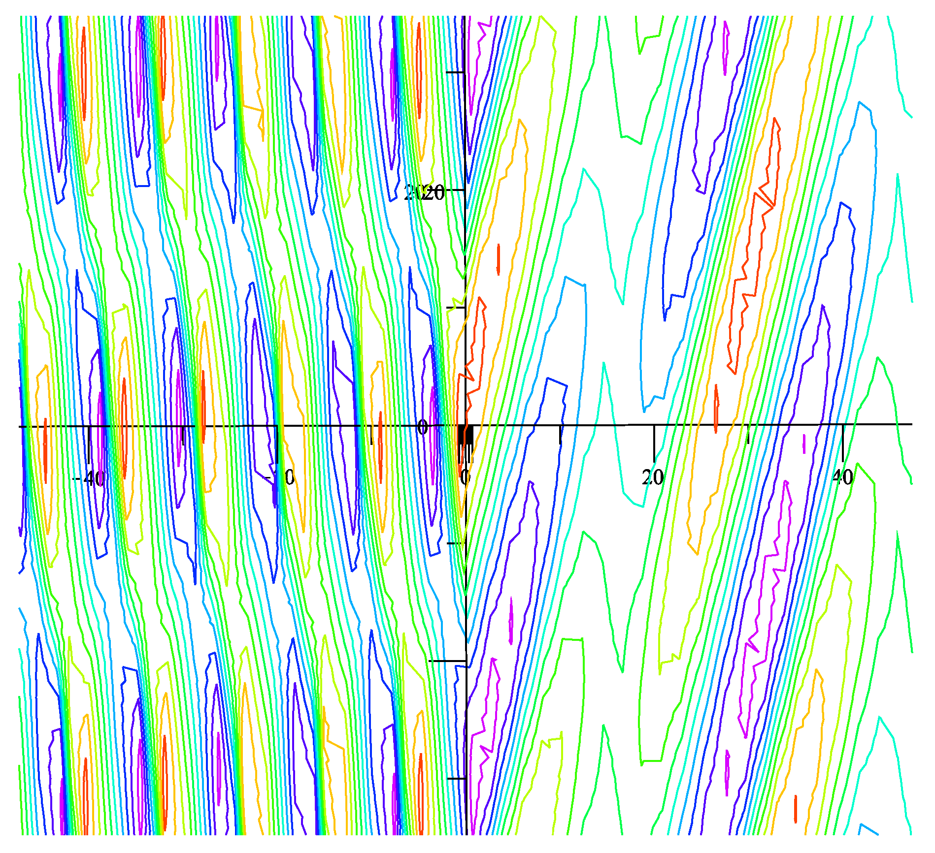
Figure 12 shows the contour map of H field at the interface between the vacuum ( x < 0 ) and the effective double negative material ( x > 0 ).
Now consider another signal but with with ω L / ω p = 0.95 and ω U / ω p = 0.96 . The paper [36] shows that when the dimensionless frequency ω ω p lies in the interval [ 0.95 , 0.96 ] , the effective permittivity and effective permeability of the material are simultaneously positive. Let the dimensionless center frequency ω ¯ ω p = 0.955 and the incident angle θ i = 16 . Note that the refractive angle θ t = 75.57 when ω ω p = 0.95 and θ t = 55.00 when ω ω p = 0.96 . 
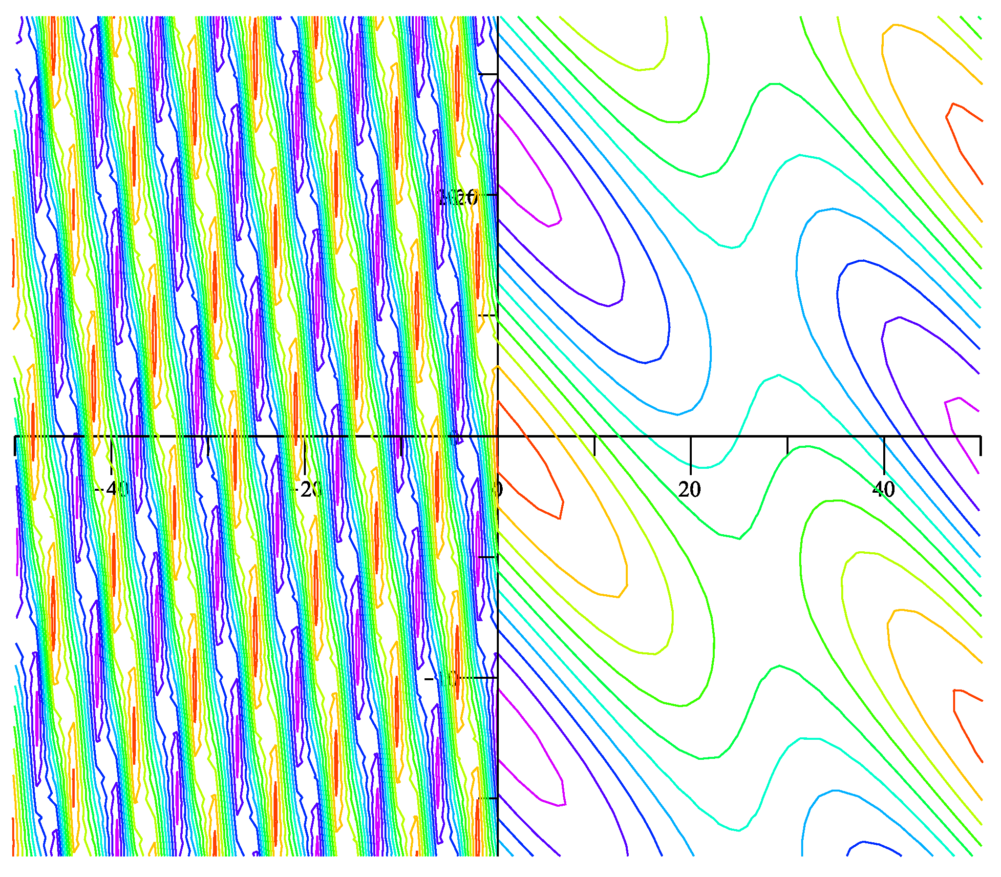
Figure 13 gives the contour map of H field at the interface between the vacuum ( x < 0 ) and the effective double positive material ( x > 0 ).

6. Conclusions

We have considered the refraction of incoming signals traveling from free space into a metamaterial. The metamaterial considered in this paper is made up of a periodic sub-wavelength array of non-magnetic resonators. We show that the resonator geometry influences the direction of the transmitted signal depending on the signal’s center frequency and bandwidth. Here the directionality of the refracted signal and its frequency dependence is explicitly controlled by sub-wavelength resonances that can be controlled by adjusting the geometry of the sub-wavelength scatters. We present the time domain representation for the refracted signals and use this representation in the numerical simulation of their behavior. The simulation shows that the medium can be designed to simultaneously refract signals both positively or negatively depending on the signal’s center frequency and band width.

Author Contributions

Conceptualization, Y.C. and R.L.; methodology, Y.C. and R.L.; software, Y.C.; validation, Y.C. and R.L.; writing—original draft preparation, Y.C. and R.L.; writing—review and editing, Y.C. and R.L.; funding acquisition, R.L.

Funding

This research was funded by NSF Grant DMS-1813698.

Conflicts of Interest

The authors declare no conflict of interest. The funders had no role in the design of the study; in the collection, analyses, or interpretation of data; in the writing of the manuscript, or in the decision to publish the results.

References

  1. Bohren, C.F.; Huffman, D.H. Absorption and Scattering of Light by Small Particles; Wiley: Hoboken, NJ, USA, 2004. [Google Scholar]
  2. Pendry, J.; Holden, A.; Robbins, D.; Stewart, W. Magnetisim from conductors and enhanced nonlinear phenomena. IEEE Trans. Microw. Theory Tech. 1999, 47, 2075–2084. [Google Scholar] [CrossRef]
  3. Pendry, J.; Holden, A.; Robbins, D.; Stewart, W. Low frequency plasmons in thin-wire structures. J. Phys. Condens. Matter. 1998, 10, 4785–4809. [Google Scholar] [CrossRef] [Green Version]
  4. Smith, D.R.; Padilla, W.; Vier, D.; Nemat-Nasser, S.; Schultz, S. Composite medium with simultaneously negative permeability and permittivity. Phys. Rev. Lett. 2000, 84, 4184–4187. [Google Scholar] [CrossRef] [PubMed]
  5. Shelby, R.A.; Smith, D.R.; Schultz, S. Experimental verification of a negative index of refraction. Science 2001, 292, 77–79. [Google Scholar] [CrossRef] [PubMed]
  6. Ziolkowski, R.W. Pulsed and CW Gaussian beam interactions with double negative metamaterial slabs. Opt. Express 2003, 11, 662–681. [Google Scholar] [CrossRef] [PubMed]
  7. Babych, N.O.; Kamotski, I.V.; Smyshlyaev, V.P. Homogenization of spectral problems in bounded domains with doubly high contrast. Netw. Heterog. Med. 2008, 3, 413–436. [Google Scholar]
  8. Bouchitté, G.; Schweizer, B. Homogenization of Maxwell’s equations in a split ring geometry. Multiscale Model. Simul. 2010, 8, 717–750. [Google Scholar] [CrossRef]
  9. Bouchitté, G.; Felbacq, D. Homogenization near resonances and artificial magnetism from dielectrics. C. R. Math. 2004, 339, 377–382. [Google Scholar] [CrossRef]
  10. Dolling, G.; Enrich, C.; Wegener, M.; Soukoulis, C.M.; Linden, S. Low-loss negative-index metamaterial at telecommunication wavelengths. Opt. Lett. 2006, 31, 1800–1802. [Google Scholar] [CrossRef] [PubMed]
  11. Fortes, S.P.; Lipton, R.P.; Shipman, S.P. Convergent power series for fields in positive or negative high-contrast periodic media. Commun. Part. Differ. Equat. 2011, 36, 1016–1043. [Google Scholar] [CrossRef]
  12. Huangfu, J.; Ran, L.; Chen, H.; Zhang, X.; Chen, K.; Grzegorczyk, T.M.; Kong, J.A. Experimental confirmation of negative refractive index of a metamaterial composed of Ω-like metallic patterns. Appl. Phys. Lett. 2004, 84, 1537. [Google Scholar] [CrossRef]
  13. Kohn, R.; Shipman, S. Magnetism and homogenization of micro- resonators. Multiscale Model. Simul. 2008, 7, 62–92. [Google Scholar] [CrossRef]
  14. Lipton, R.; Polizzi, A.; Thakur, L. Novel metamaterial surfaces from perfectly conducting subwavelength corrugations. SIAM J. Appl. Math. 2017, 77, 1269–1291. [Google Scholar]
  15. Lipton, R.; Schweizer, B. Effective Maxwell’s equations for perfectly conducting split ring resonators. Arch. Ration. Mech. Anal. 2018, 229, 1197–1221. [Google Scholar] [CrossRef]
  16. Shalaev, V.M.; Cai, W.; Chettiar, U.K.; Yuan, H.K.; Sarychev, A.K.; Drachev, V.P.; Kildishev, A.V. Negative index of refraction in optical metamaterials. Opt. Lett. 2005, 30, 3356–3358. [Google Scholar] [CrossRef] [PubMed]
  17. Zhang, F.; Potet, S.; Carbonell, J.; Lheurette, E.; Vanbesien, O.; Zhao, X.; Lippens, D. Negative-zero-positive refractive index in a prism-like omega-type metamaterial. IEEE Trans. Microw. Theory Tech. 2008, 56, 2566–2573. [Google Scholar] [CrossRef]
  18. Zhang, S.; Fan, W.; Minhas, B.K.; Frauenglass, A.; Malloy, K.J.; Brueck, S.R.J. Midinfrared resonant magnetic nanostructures exhibiting a negative permeability. Phys. Rev. Lett. 2005, 94, 037402. [Google Scholar] [CrossRef] [PubMed]
  19. Zhikov, V.V. On an extension of the method of two-scale convergence and its applications. Sb. Math. 2000, 191, 973–1014. [Google Scholar] [CrossRef]
  20. Zhou, X.; Zhao, X.P. Resonant condition of unitary dendritic structure with overlapping negative permittivity and permeability. Appl. Phys. Lett. 2007, 91, 181908. [Google Scholar] [CrossRef]
  21. Wheeler, M.S.; Aitchison, J.S.; Mojahedi, M. Coated non-magnetic spheres with a negative index of refraction at infrared frequencies. Phys. Rev. B 2006, 73, 045105. [Google Scholar] [CrossRef]
  22. Yannopapas, V. Negative refractive index in the near-UV from Au-coated CuCl nanoparticle superlattices. Phys. Status Solidi (RRL) 2007, 1, 208–210. [Google Scholar] [CrossRef]
  23. Yannopapas, V. Artificial magnetism and negative refractive index in three-dimensional metamaterials of spherical particles at near-infrared and visible frequencies. Appl. Phys. A 2007, 87, 259–264. [Google Scholar] [CrossRef]
  24. Huang, K.C.; Povinelli, M.L.; Joannopoulos, J.D. Negative effective permeability in polaritonic photonic crystals. Appl. Phys. Lett. 2004, 85, 543. [Google Scholar]
  25. Peng, L.; Ran, L.; Chen, H.; Zhang, H.; Kong, L.A.; Grzegorczyk, T.M. Experimental observation of left-handed behavior in an array of standard dielectric resonators. Phys. Rev. Lett. 2007, 98, 157403. [Google Scholar] [CrossRef] [PubMed]
  26. Vynck, K.; Felbacq, D.; Centeno, E.; Cabuz, A.I.; Cassagne, D.; Guizal, B. All-dielectric rod-type metamaterials at optical frequencies. Phys. Rev. Lett. 2009, 102, 133901. [Google Scholar] [CrossRef] [PubMed]
  27. Alu, A.; Engheta, N. Dynamical theory of artifical optical magnetism produced by rings of plasmonic nanoparticles. Phys. Rev. B 2008, 78, 085112. [Google Scholar] [CrossRef]
  28. Shvets, G.; Urzhumov, Y. Engineering the electromagnetic properties of periodic nanostructures using electrostatic resonances. Phys. Rev. Lett. 2004, 93, 243902. [Google Scholar] [CrossRef] [PubMed]
  29. Service, R.F. Next Wave of metamaterials hopes to fuel the revolution. Science 2010, 327, 138–139. [Google Scholar] [CrossRef] [PubMed]
  30. Shalaev, V. Optical negative-index metamaterials. Nat. Photonics 2007, 1, 41–48. [Google Scholar] [CrossRef]
  31. Fujii, G.; Matsumoto, T.; Takahashi, T.; Ueta, T. A study on the effect of filling factor for laser action in dielectric random media. Appl. Phys. A 2012, 107, 33–42. [Google Scholar] [CrossRef]
  32. Fujii, G.; Matsumoto, T.; Takahashi, T.; Ueta, T. Study on transition from photonic-crystal laser to random laser. Opt. Express 2012, 20, 7300–7315. [Google Scholar] [CrossRef] [PubMed]
  33. Wiersma, D.S. Disordered photonics. Nat. Photonics 2013, 7, 188–196. [Google Scholar] [CrossRef]
  34. Chen, Y.; Lipton, R. Resonance and double negative behavior in metamaterials. Arch. Ration. Mech. Anal. 2013, 209, 835–868. [Google Scholar] [CrossRef]
  35. Chen, Y.; Lipton, R. Tunable double negative band structure from non-magnetic coated rods. New J. Phys. 2010, 12, 083010. [Google Scholar] [CrossRef] [Green Version]
  36. Chen, Y.; Lipton, R. Double Negative Dispersion Relations from Coated Plasmonic Rods. Multiscale Model. Simul. 2013, 11, 192–212. [Google Scholar] [CrossRef] [Green Version]
  37. Chen, Y.; Lipton, R. Multiscale methods for engineering double negative metamaterials. Photonics Nanostruct. Fundam. Appl. 2013, 11, 442–452. [Google Scholar] [CrossRef]
  38. Bergman, D.J. The dielectric constant of a simple cubic array of identical spheres. J. Phys. C Solid State Phys. 1979, 12, 4947–4960. [Google Scholar] [CrossRef]
  39. McPhedran, R.C.; Milton, G.W. Bounds and exact theories for the transport properties of inhomogeneous media. Appl. Phys. A 1981, 26, 207–220. [Google Scholar] [CrossRef]
Figure 1. Photonic crystal made from coated rods.
Applsci 08 01942 g001
Figure 2. Unit cell containing a single rod cross section. R represents the rod cross section, P the plasmonic coating and H the host.
Applsci 08 01942 g002
Figure 3. The relation between μ e f f and ω 2 / c 2 .
Applsci 08 01942 g003
Figure 4. The relation between ϵ e f f 1 and ω 2 / c 2 .
Applsci 08 01942 g004
Figure 5. The leading order dispersion relation over two selected intervals I n and I n .
Applsci 08 01942 g005
Figure 6. The crosssection of the coated fiber with core radius a and coating radius b.
Applsci 08 01942 g006
Figure 7. Incident wave without any reflection for ω p t = 5 .
Applsci 08 01942 g007
Figure 8. H field in vacuum with interaction between incident and reflective waves for ω p t = 5 .
Applsci 08 01942 g008
Figure 9. Transmitted wave motion from the bottom to the top for ω p t ranging from 5 to 9 in the steps of 2. The group velocity has the forward direction.
Applsci 08 01942 g009
Figure 10. Transmitted wave motion from the bottom to the top for ω p t ranging from 5 to 7 in the steps of 1. The phase velocity has the backward direction.
Applsci 08 01942 g010
Figure 11. H field at the interface between the vacuum ( x < 0 ) and the metamaterial with negative index of refraction ( x > 0 ) from the bottom to the top for ω p t ranging from 5 to 9 in the steps of 2.
Applsci 08 01942 g011
Figure 12. Contour map of H field with the incident angle θ i = 16 at the interface between the vacuum ( x < 0 ) and effective double negative material ( x > 0 ) when ω p t = 0 .
Applsci 08 01942 g012
Figure 13. Contour map of H field with the incident angle θ i = 16 at the interface between the vacuum ( x < 0 ) and effective double positive material ( x > 0 ) when ω p t = 0 .
Applsci 08 01942 g013
Table 1. The changes of the negative index band when inner radius and outer radius vary. In each cell, the upper and lower numbers denote the band width and center frequency, respectively.
a = 0.5 b a = 0.55 b a = 0.6 b a = 0.65 b
b = 0.3000 0.0332
( 0.8919 )
b = 0.350 0.02733 0.03824 0.04425
( 0.9003 ) ( 0.8315 ) ( 0.7716 )
b = 0.4 0.03541 0.04204 0.04893 0.05579
( 0.8707 ) ( 0.7960 ) ( 0.7345 ) ( 0.6830 )
b = 0.45 0.04366 0.05143 0.05944 0.06801
( 0.7795 ) ( 0.7141 ) ( 0.6605 ) ( 0.6161 )

