Article

An Enhancing Fault Current Limitation Hybrid Droop/V-f Control for Grid-Tied Four-Wire Inverters in AC Microgrids

by
Daniel Heredero-Peris
1,*,†,
Cristian Chillón-Antón
1,†,‡,
Marc Pagès-Giménez
1,†,
Daniel Montesinos-Miracle
1,†,
Mikel Santamaría
2,‡,
David Rivas
2 and
Mónica Aguado
2
1
Centre d’Innovació Tecnològica en Convertidors Estàtics i Accionaments (CITCEA-UPC), Departament d’Enginyeria Elèctrica, Universitat Politècnica de Catalunya, ETS d’Enginyeria Industrial de Barcelona, Avinguda Diagonal, 647, Pl. 2, 08028 Barcelona, Spain
2
Renewable Energies Grid Integration Department, CENER (Renewable Energy National Centre of Spain), 31621 Navarra, Spain
*
Author to whom correspondence should be addressed.
These authors contributed equally to this work.
The two emails [email protected] and [email protected] are office email.
Appl. Sci. 2018, 8(10), 1725; https://doi.org/10.3390/app8101725
Submission received: 30 July 2018 / Revised: 13 September 2018 / Accepted: 19 September 2018 / Published: 22 September 2018
(This article belongs to the Special Issue Microgrids)

Abstract

:
Microgrid integration and fault protection in complex network scenarios is a coming challenge to be faced with new strategies and solutions. In this context of increasing complexity, this paper describes two specific overload control strategies for four-wire inverters integrated in low voltage four-wire alternating current (AC) microgrids. The control of grid-tied microgrid inverters has been widely studied in the past and mainly focused on the use of droop control, which hugely constrains the time response during grid-disconnected operation. Taking into account the previous knowledge and experience about this subject, the main contribution of these two proposals regards providing fault current limitation in both operation modes, over-load capability skills in grid-connected operation and sinusoidal short-circuit proof in grid-disconnected operation. In the complex operation scenarios mentioned above, a hybrid combination of AC droop control based on dynamic phasors with varying virtual resistance, and voltage/frequency master voltage control for grid-(dis)connected operation modes are adopted as the mechanism to enhance time response. The two proposals described in the present document are validated by means of simulations using Matlab/Simulink and real experimental results obtained from CENER (The National Renewable Energy Centre) experimental ATENEA four-wire AC microgrid, obtaining time responses in the order of two-three grid cycles for all cases.

1. Introduction

In the coming years, it is expected that classical electrical grids will drive forward to a smarter, more flexible, reliable, efficient and bidirectional format leading to a more complex framework. All of these benefits should be supported by an appropriate infrastructure. In this context, microgrids [1,2], and mainly alternating current (AC) microgrids, play a key role in a new electrical paradigm pushed by the increasing penetration of Distributed Energy Resources (DER). This paradigm will deal with the variability and unpredictability associated with DERs and local demand fluctuations. This versatility generates a way to delay the renovation of an aged infrastructure that cannot withstand an existing rising demand [3]. A new outline, constituted by several interconnected AC/DC (direct current) microgrids or nano-grids [4], conventional energy sources, and loads will create future viable smartgrids [5].
Microgrids can provide potential economic and environmental benefits, but their implementation implies great technical difficulties in control, energy/power management and protection. Some authors focus on the low level loops for the inverters’ operation; AC droop [6,7,8,9], voltage and current control loops [10,11,12]. Other ones concentrate on the high management level based on cooperative distributed strategies [13,14] or optimal-smart operation [15,16,17,18]. Considering the previously mentioned antecedents in the literature, the authors of this paper consider it very relevant to pay attention to fault protection [19,20] and secure operation in seamless transference between operation modes [12,21,22,23].
On one hand, in traditional AC four-wire distribution systems, protective device coordination during faults is achieved by selecting appropriate circuit-breaker current–time characteristics under clear regulations. This choice does not imply intercomponent communication [21,24] and assumes high short-circuit power levels [24]. However, the situation is the opposite in the case of microgrids based on power electronics, the over-load capability being, hereinafter Fault Current Limitation (FCL), constrained. In a microgrid context, it should be adaptive and fast in terms of voltage and current limitations [25], and should be able to behave sinusoidally to not affect the response of conventional protective breakers.
On the other hand, inverters in a microgrid can play two main roles: one as a controlled voltage source and the other as a controlled current source [26], and can adopt two control hierarchies, master–slave or peer-to-peer [27]. In addition, in the peer-to-peer hierarchy, the conventional AC droop voltage control strategy, based on the steady-state or quasi-static power transference model between AC sources [6,28], is a widely applied alternative to face both operation modes (grid-(dis)connected) and parallellize various inverters, but generates poor dynamics, mainly in grid-disconnected operation. This last situation get worse with the typical use of low-pass filters to emulate synchronous generator mechanical inertias [28]. The combination of droop-based control with the use of virtual impedances is a widespread mechanism to support the soft-start challenge under a peer-to-peer hierarchy [29,30]. Furthermore, conventional AC droop control presents low adaptability when the operation point differs significantly from the planned rated point. In this situation, the recent use of dynamic phasors can be used to improve the adaptability of conventional AC droop control strategies [31].
The motivation of this paper regards considering strategies that provide FCL capabilities in both operation modes. It can be found in [24,32,33] examples based on separating the fault from the grid rapidly but without an AC fault management strategy. However, previous examples as well as others, focus on faults at the DC-link of the inverter [34], observing the effect on the AC side. On the other side, others references concentrate directly on DC microgrids [35,36,37]. The last two scenarios mentioned above are far away from this paper target. Another studied solution is to face FCL under the assumption that the inverter is droop-based in both operation modes. In [38,39], examples for three-phase three-wire microgrids are exposed. Different types of short circuits are studied in [38], but the fault current limitations offer dynamics of about 200 ms to achieve steady-state, while in [39] only a tretrapolar short-circuit is evaluated obtaining time responses of about 100 ms. In [40], some results are just simulated for AC droop-based four-wire systems. Finally, other alternatives exist applied to series filters or obtaining FCL by changing the output inductances as detailed in [41,42].
The main contribution of the present paper is the demonstration by simulation and real results of the advantages and flexibility of a fast time response hybrid combination of voltage control techniques that ensures proper FCL capabilities introducing two strategies for this purpose: one for each operation mode. This allows for applying specific control strategies and solutions in a context of increasing complexity scenarios avoiding the use of generic solutions that are not always the most appropriate ones.
Firstly, the AC droop control based on dynamic phasors is adopted for the grid-connected mode, but a master voltage-frequency (V/f) control strategy is embraced for the grid-disconnected mode, offering better dynamic responses during the grid-disconnected operation thanks to disabling the AC droop loop. The use of a variable virtual resistance supports not only soft-starts but also the transference between the operation modes. Varying virtual resistance enhances the voltage restoration during the transference.
Secondly, two control strategies will assist the FCL capability of the inverter connected to an AC microgrid. An over-load supervisor is proposed to characterize and limit the over-load magnitude, providing thermal recovery when extra current has to be dispatched during grid-connected mode. In addition, a short-circuit proof strategy supports the operation of the inverter under different short-circuit situations and fault clearances for grid-disconnected operation, obtaining time responses below 60 ms. To achieve the same response from the protective devices’ viewpoint, the short-circuit proof algorithm allows for maintaining current and voltage sinusoidal and totally controlled, as required in a microgrid operation framework.
All strategies are thought to be compatible with a four-wire microgrid because, as detailed in [43,44,45], this is the proper solution for addressing independently three-phase current control and facing imbalances. These strategies become an efficient way to face common situations in low voltage microgrids interfaced with distribution networks.
Thus, the paper is organized as follows. Section 2 defines the system. Section 3 describes the proposed strategies for the FCL and the adaptive virtual resistance mechanism adopted for a seamless smooth transference. Section 4 presents the simulated results using Matlab/Simulink (R2017b, The MathWorks, Inc., Natick, MA, USA, 1984) and exposes the experimental ones validated in the experimental ATENEA four-wire microgrid at The National Renewable Energy Centre (CENER). Finally, Section 5 provides the conclusions.

2. System Definition

The following sub-sections define the experimental ATENEA microgrid and the converter considered in this paper.

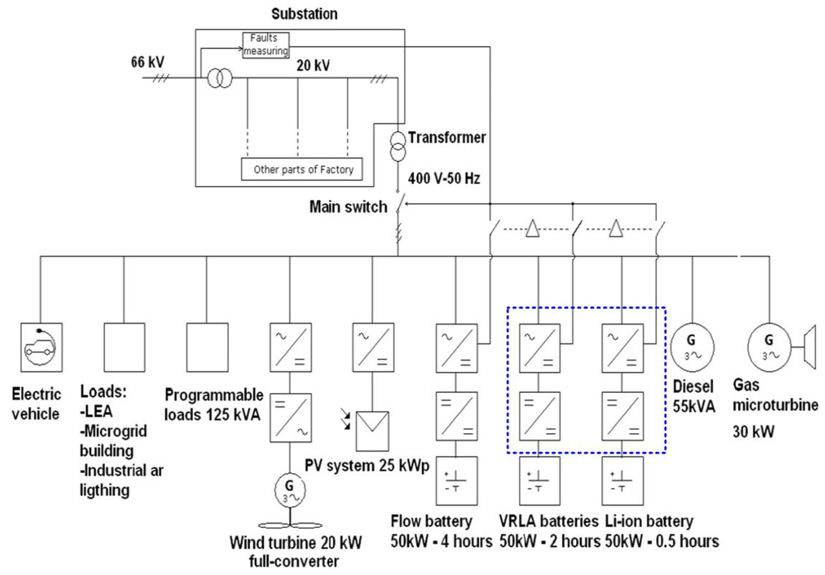
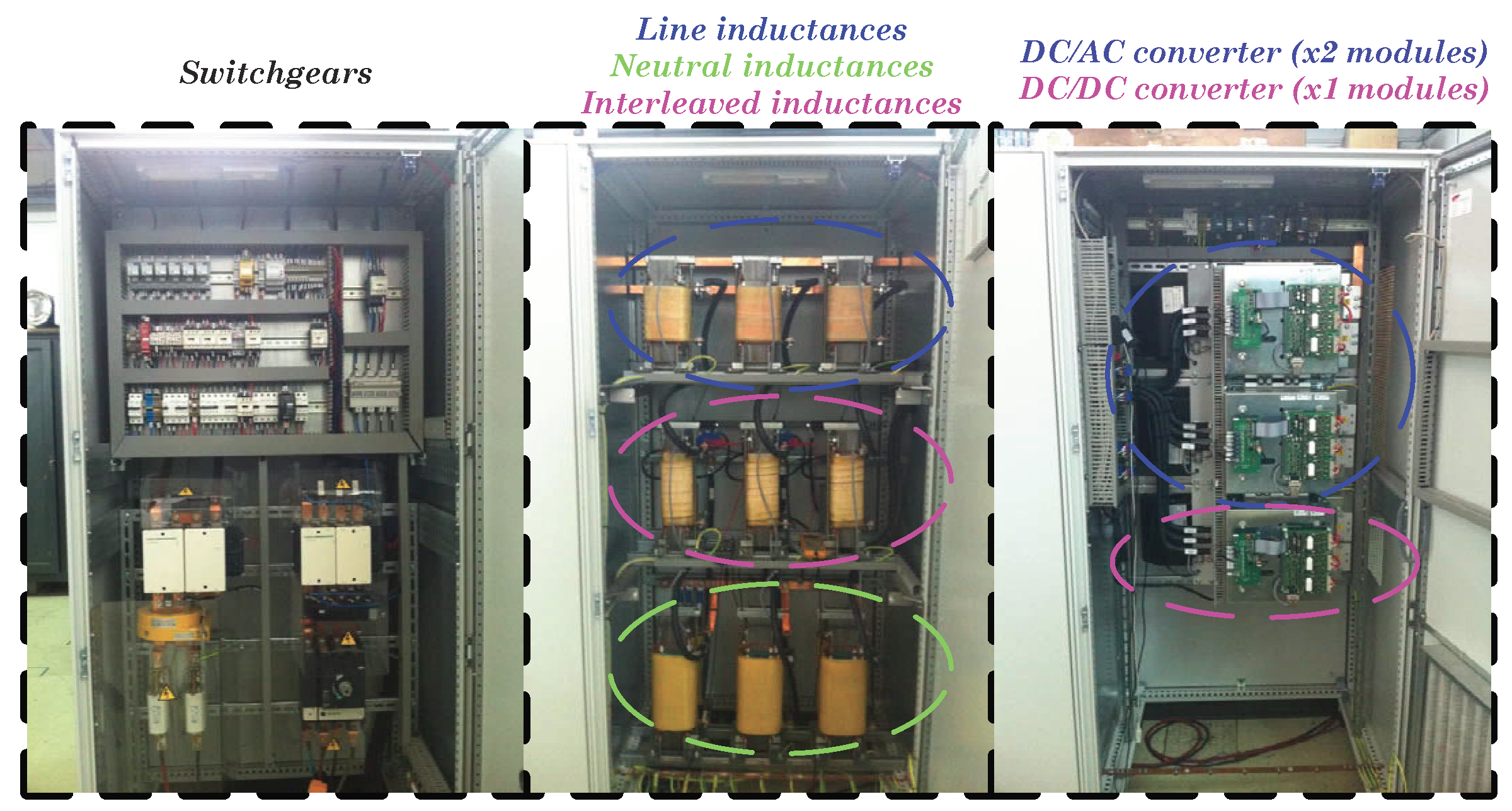
2.1. The Experimental ATENEA Microgrid
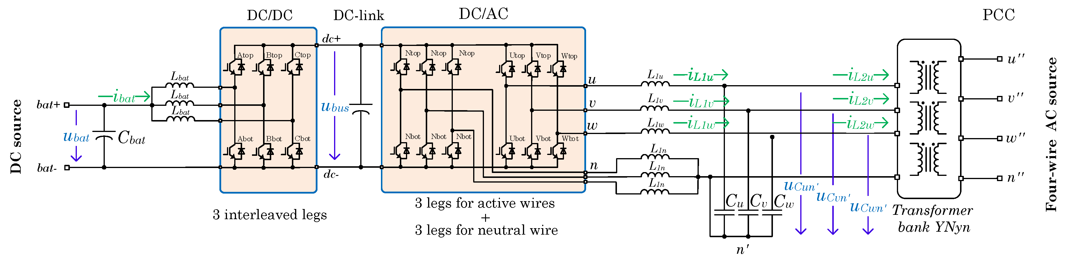
The Renewable Energy Grid Integration Department in CENER (National Renewable Energy Centre of Spain) has developed and deployed a microgrid (ATENEA) placed in the Rocaforte industrial area (town of Sangüesa, Navarra, Spain) according to the interest in an industrial test scenario and environment. The generation equipment of the facility can be seen in Figure 1.
It consists of an AC architecture with total installed power of about 120 kW that can supply part of the Wind Turbine Test Laboratory (LEA), electric loads and Rocaforte industrial lighting area. It also can be used as a test-bench for different generation and storage technologies and control strategies. The generation equipment available in the facility can be seen in Figure 1.
The ATENEA microgrid structure is based on an AC low voltage three-phase, four-wire bus (400 V, 50 Hz) connected to all of the equipment. This experimental microgrid has two configurations: grid-connected and grid-disconnected. Its main objective is to manage generation and demand in order to obtain high ratios of energy self-efficiency. In grid-connected mode, the microgrid is connected to the network and the V/f performance is fixed by its own network. In the grid-disconnected scenario, one of the converters linked with an energy storage system (flow battery, Valve-Regulated Lead-Acid (VRLA) battery, Li-ion battery) or a diesel generator is configured to form the grid, mastering the V/f. In this way, the ATENEA microgrid adopts a master–slave control in the grid-isolated configuration and the slaves work under a PQ control, P and Q being active and reactive power, respectively.

2.2. The Converter

According to Section 2.1, a two-stage converter is considered to interface with the VRLA or the Li-ion 50 kW batteries of Figure 1 (blue dashed box) with the four-wire microgrid. It has been decided to use a common two-level three-leg power stack to maintain homogeneity for both power stages (see Figure 2).
In consonance with the available storage technologies, a DC voltage u b a t range from 150 to 500 VDC is considered. With this configuration, a DC–DC converter interfaces with this wide DC voltage range by means of a three-phase interleaved topology. By the use of an interleaved topology, the output inductive filter size is split and reduced, so it makes for easier operation and maintenance tasks. At the same time, high power converters could be designed with lower current modules, reducing the voltage and current ripple in the DC-link and decreasing the power capacity of the inductors [46]. Thus, as cited in [47], the reliability of an interleaved DC–DC converters increases compared with conventional one leg devices.
In order to manage AC unbalanced loads, an inverter topology able to control any current sequence is required. The inverter stage is constituted by two three-leg bridges: one dedicated for the active phases and the other one for the neutral wire. This configuration allows for controlling each line current independently using optimized modulation techniques such as Space Vector Pulse Width Modulation (SVPWM) [48]. An LCL-type coupling filter completes the inverter where an isolation free-flux YNyn transformer bank is assumed as part of the LCL-type filter providing galvanic isolation and offering different possible neutral schemes [49].

3. Control Strategies

The following sub-sections define the main control strategies of the proposed converter in Section 2 that will be applied in the experimental ATENEA microgrid.

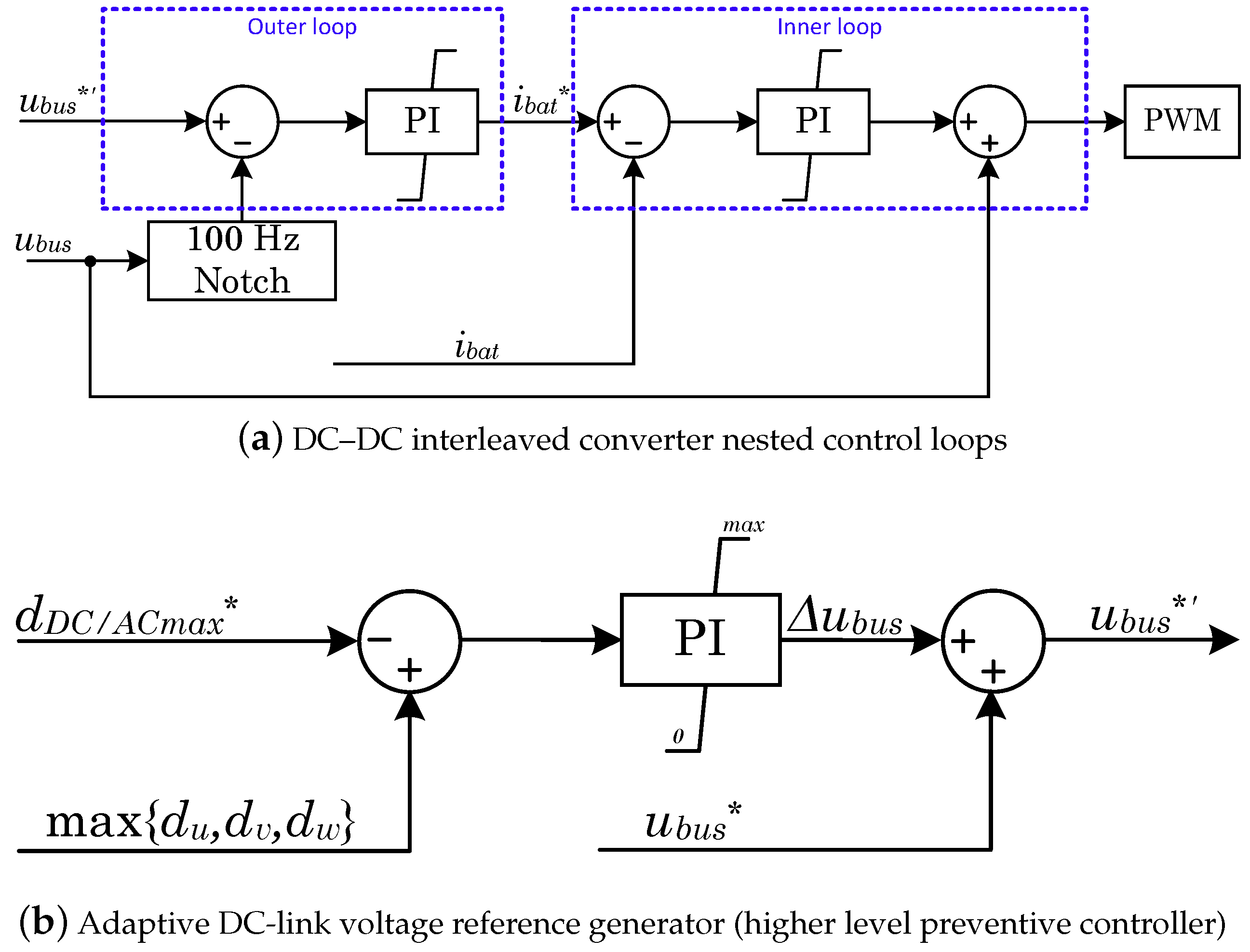
3.1. DC–DC Interleaved Converter Control

DC–DC power stage is not the aim of this paper, but, in the context of this paper, it has been considered relevant to briefly mention its high level control details. In the operation context described in this document, the DC–AC inverter operation requires a proper DC-link voltage level to hold an adequate behaviour under unbalances or nonlinear needs. In addition, it has been considered that the DC energy storage system presents a large voltage range. Due to this voltage wide voltage range, an uncontrolled constant DC-link voltage level can affect inverter’s operation. The purpose of the DC–DC converter is to step-up the voltage of the storage system and provide an autonomous way to regulate the DC-link voltage level against different AC requirements.
The DC–DC converter is controlled by means of two nested control loops, as shown in Figure 3a. The inner control loop manages the battery inductor, L b a t , and limits the maximum desired battery current, i b a t . As detailed in Section 2.2, an interleaved topology is chosen, so a 2 π /3 rad/s shifted phase PWM strategy is used with the same duty cycle for all the converter’s legs. The outer control loop controls the DC-link voltage, u b u s . Because of the unbalanced nature of AC connected loads, low frequency voltage ripples (at ≃100 Hz) in the DC-link can be severe. This voltage control loop needs a high bandwidth to overcome this ripple and keep constant u b u s . Thus, an adaptive 100 Hz notch filter [50] is used in the feedback control chain for this purpose to quickly compensate for any variation around the fundamental rated grid frequency (50 Hz).
To avoid over-modulation situations in the DC–AC stage, a preventive controller is suggested at the higher level of the DC–DC control scheme in order to provide an increment of u b u s , Δ u b u s , to the rated DC-link voltage. Thus, the reference u b u s * = u b u s * + Δ u b u s is generated where u b u s * is the desired standard DC-link voltage, as can be deduced from Figure 3b. The maximum available duty cycle of the inverter, d D C A C m a x * , is compared with the maximum of the duties of the inverter’s active phases ( d u , d v and d w ). If there is not enough DC bus for the inverter, the DC reference is stepped up to its maximum threshold, taking into account the limitations of the DC-link. In another case, Δ u b u s is equal to zero in the steady-state as a consequence of the lower saturation limit of the PI controller, as shown in Figure 3b. Thanks to this method, the DC-link voltage is increased as required only under imminent over-modulation situation.

3.2. DC–AC Four-Leg Converter Control

The DC–AC power stage is responsible for operating the AC side in the two operation modes defined in Section 2.1: grid-connected and grid-disconnected. In this paper, and following the operation philosophy of ATENEA’s operation, a strategy based on maintaining the voltage source behaviour in both modes has been adopted. However, and as a difference from the solutions proposed in the literature review of Section 1, the grid-connected operation adopts an AC droop control, but, in grid-disconnected operation, the voltage behaviour is maintained disabling the external droop loop. In this last case, the voltage/frequency control is assumed by the inverter being the voltage master of the microgrid. In this scenario, the obtained dynamics are less limited in time-response due to the absence of droop constraints.
As defined in Section 2, the inverter is based on a three-phase four-leg topology to be fully compatible with ATENEA four-wire microgrid. This allows the inverter to be controlled by means of three independent single phase systems in order to provide direct, indirect and homopolar sequence control capability. Each phase has its own master AC droop control (only for grid-connected mode) and two inner cascaded stationary frame controllers [51] for the voltage ( u C x n ) and current ( i L 1 x ) loops, x phase being u, v or w. The inner loops are tuned considering [49,52] and the tuning values are presented in Section 4.

3.2.1. Control Assumptions

Classical AC droop control operation principles are obtained from the steady-state equations that describe the power flow between two AC voltage sources connected by an inductive line, as widely detailed in [6,28]. A predominant resistive behaviour is adopted by using the virtual impedance concept [29,30] to provide a reliable relationship between the sets active-reactive power and voltage-frequency, being as independent as possible from the grid impedance. The virtual resistance concept is described in Figure 4. In Figure 4a, u C designs the controlled AC voltage, u P C C is the voltage of Point of Common Coupling (PCC), R 2 the physical equivalent series resistance of L 2 , and R v is the value of the virtual resistance (see Figure 2).
The adaptive virtual resistance concept is currently used for hot-swapping (soft-start) [6] and to smooth the effect of grid fluctuations. In this case, it is also applied to enhance the transference between operation modes, as is later shown in Section 4.2. It should be noted that the virtual resistance should be disabled progressively to not affect the operation of a pure V/f strategy in the grid-disconnected mode. Figure 4b illustrates the proposed behaviour of the R v module during and between the operation modes. Furthermore, as it has been aforementioned, this fact makes it possible to improve the time response performance in grid-disconnected mode thanks to the master voltage role change between the mains and the converter.
It is possible to deduce the dynamic AC control droop schemes depicted in Figure 5 under a resistive behaviour assumption and considering dynamic phasors [31]. This control schemes are the basis control schemes adopted for the grid-connected operation in the paper. In Figure 5, G c t r l represents the transfer function of the AC droop control law between the node A that is the AC controlled capacitor and a node B corresponding to the PCC. For the G c t r l , it is assumed that a τ f time constant for emulating mechanical inertias of synchronous generators [28]. P * / Q * - P / Q are the active/reactive powers set-points and measured values, and U A and U B represent the voltage at the mentioned nodes A and B. The ω U B is the angular frequency at the PCC, θ U A and θ U 2 are again the phases at nodes A and B, respectively. Finally, R and L are the total resistive and inductive part between A and B. Note that R is the addition of the real equivalent series resistance of the wiring, the output transformer involved and the forced virtual part R v .

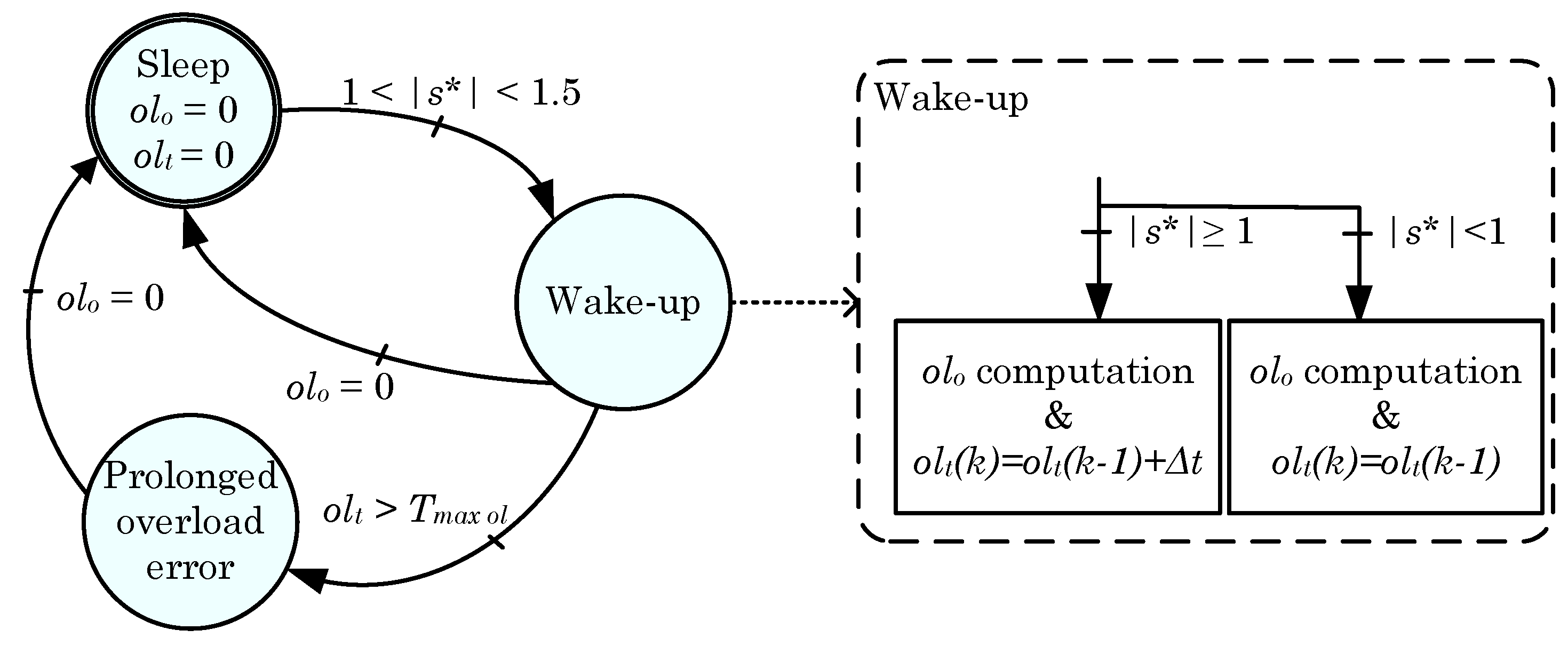
3.2.2. Power Over-Load Supervisor for the Grid-Connected Mode

As it is well known, the inertial and over-load capability of power electronics is limited. Moreover, it is common to consider pulsed drain currents of two to three times the continuous drain current for about 1 ms. On the contrary, in traditional AC systems, the rotary machines and transformers can be over-loaded up to 20–30 times in a timescale of minutes [24]. In this case, it has been considered to over-size the converter allowing a certain over-load capability. This fact provides a more flexible interaction between the inverter and the AC microgrid. The oversizing is achieved using high current switching devices. This choice allows for a more compact converter placing the burden of oversizing only on the cost of switching devices, a not really sensitive part today. Thus, the cooling system is designed to suit the nominal power. However, the thermal time lag of the used cooling method is usually enough and within the range of seconds to minutes. Furthermore, the use of thermal masses such as aluminium plates, or the consideration of phase change materials are options to increase the thermal inertia [53,54], being a good trade-off between cost and volume, if required.
In order to manage the over-load capability, the maximum AC current is handled by a power over-load supervisor algorithm based on thermal criteria. This current limitation is achieved by means of the apparent power s (in per unit). An over-load observer, o l o , limits the power per phase. The over-load observer fulfills this task through the formula
o l o = 0 t i 2 1 d t
based on the i 2 t computation. In this sense, the term o l o is an indicator of the over-load energy exchanged, i * is the desired current and t is the time interval of the over-current. The over-load algorithm is managed according to the state diagram shown in Figure 6. Time t begins when | s * | > 1 , s * being the maximum apparent power per phase reference. When | s * | > 1 , the observer enters to the Wake-up step, starting to compute o l o (Equation (1)) and o l t (accumulative time under the over-load situation). If the o l o value reaches zero, the observer returns to a Sleep step, where o l o and o l t are reset. If the o l o is bigger than zero, depending on the present s value, the accumulated time o l t is incremented or maintained. Keeping the o l t time constant, it is ensured that the inverter is not over-loaded intermittently producing possible thermal degradations. In the case that the o l t term becomes higher than a pre-set threshold T m a x o l , the system evolves to the Prolonged over-load error step and s is limited to 0.8. In this way, o l o is forced to decrease until zero. Then, the system evolves to the Sleep step again.

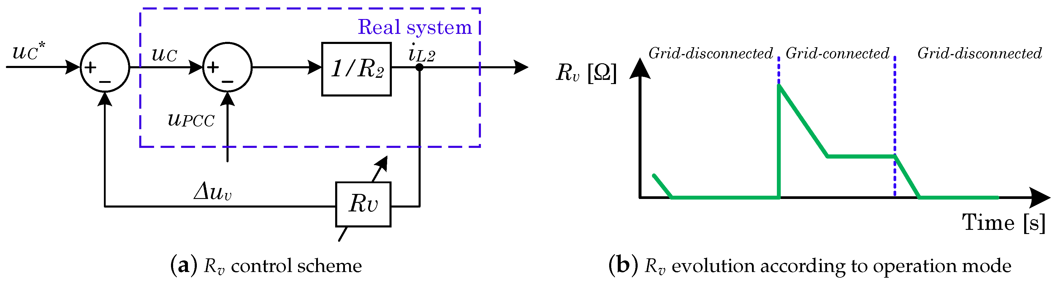
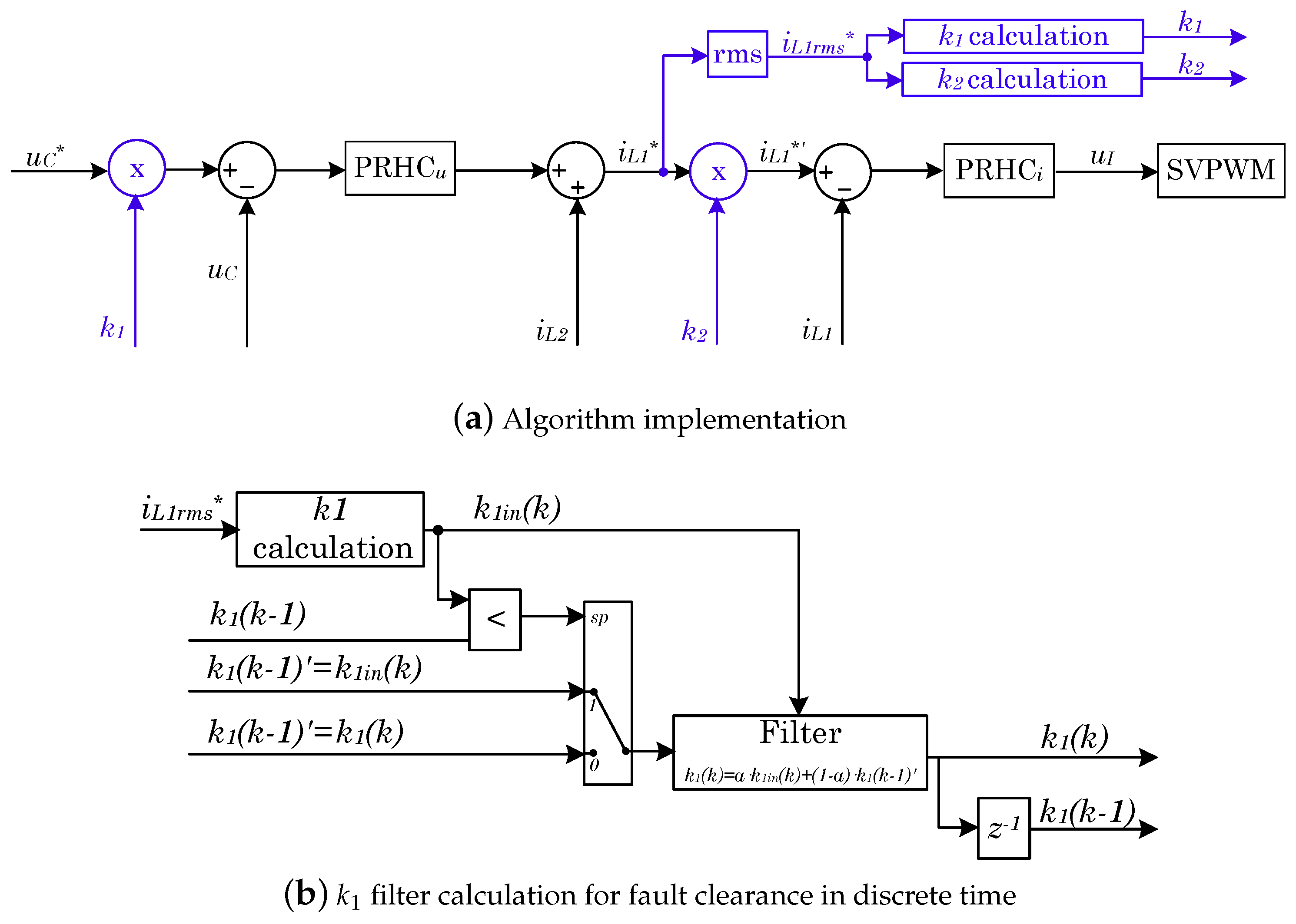
3.3. Short-Circuit Proof Algorithm for Grid-Disconnected Mode

As detailed in Section 2, the inverter operates as the voltage master when the ATENEA microgrid is grid-disconnected operated. The inverter must provide sinusoidal currents even under an over-load or short-circuit occurrence reducing the voltage accordingly. In this way, the aim of the microgrid inverter and this paper is to generate a totally controlled short-circuit power regulating sinusoidal currents. Right after, this information can be used to (re)configure certain protection devices’ distributed thresholds along the AC microgrid [25]. In this sense, the time response of the breaker that feeds the fault should be affected minimally.
Figure 7 shows the proposed block diagram of the short-circuit proof mechanism. The conventional voltage and current stationary frame controllers can be seen in black, i.e., Proportional Resonant with Harmonic Compensator (PRHC) controllers, where the subscript u and i refer to voltage and current, respectively. u C * is the objective AC capacitor voltage, U C the current AC capacitor voltage, and u I the inverters’ output voltage. i L 1 and i L 2 are the inverters’ output inductance and grid coupling inductance. The superscript * designs the reference, and the subscript r m s is the root mean square (rms) computed value.
The blue parts are added with respect to a conventional voltage-current nested loop for the short-circuit proof enhancement. The algorithm is based on the per phase rms value of the current reference on the AC side, i L 1 * , and two factors k 1 and k 2 . The first factor k 1 allows for dynamically regulating the voltage set-point to attenuate it under short-circuit or high over-load situations, as follows:
k 1 = 1 , if i rms I , K + 1 i rms K I , if I < i rms < K + 1 I , 0 , if i rms K + 1 I ,
where I is the maximum desired rated output current (at the L 1 inductance). The parameter K in k 1 calculation allows for adapting the system response speed to face the over-load or short-circuit occurrence.
The second factor k 2 limits the current to the rated value when the fault situation appears as
k 2 = 1 , if i rms < I , I i L 1 r m s * , if i rms I .
If only the previous algorithm is applied, the behaviour under the fault clearance is undesired. This is due to the fast response of the k 1 factor. To avoid this kind of undesired dynamics, when the current k 1 i n ( k ) value is higher than the previous computed one k 1 ( k 1 ) , i.e., this criterion is used as a fault recovery indicator, the applied k 1 ( k ) gain for the inner current control reference is filtered according to Figure 7b.

4. Results

This section describes a 90 kVA converter with a 50% over-load capability. A set of simulations developed in Matlab/Simulink and experimental results obtained at ATENEA microgrid are showed for the validation of the aforementioned control contributions. Hereinafter, the ITI curve [55] defined by the Information Technology Industry Council is considered as a pattern of acceptable time-duration/magnitude voltage transients.

4.1. The Converter Set-Up

The converter presented in Section 2 is based on three Semikron IGD-2-424 power stacks (Semikron, Nuremberg, Germany). The control is implemented into two TMS320F2809 DSP-based control boards, one dedicated to control the general operation state machine and the DC–DC interleaved converter and the other committed to controlling the inverter. Control strategies are executed at 8 kHz. The hardware and software relevant parameters for the DC–AC and the DC–DC converters are summarised in Table 1 and Table 2. Figure 8 shows a picture of the full converter. Furthermore, all short-circuit faults and recoveries are generated using a switch-line breaker (ABB OT200) and considering wires with less than 0.1 m Ω .

4.2. Simulated Results

This section focuses on demonstrating by the use of simulations the virtual resistance contribution to a fast and seamless transference between operation modes, the power over-load supervisor operation, and the fault current limitation strategy for an ideal (<1 m Ω impedance) short-circuit occurrence and clearance.

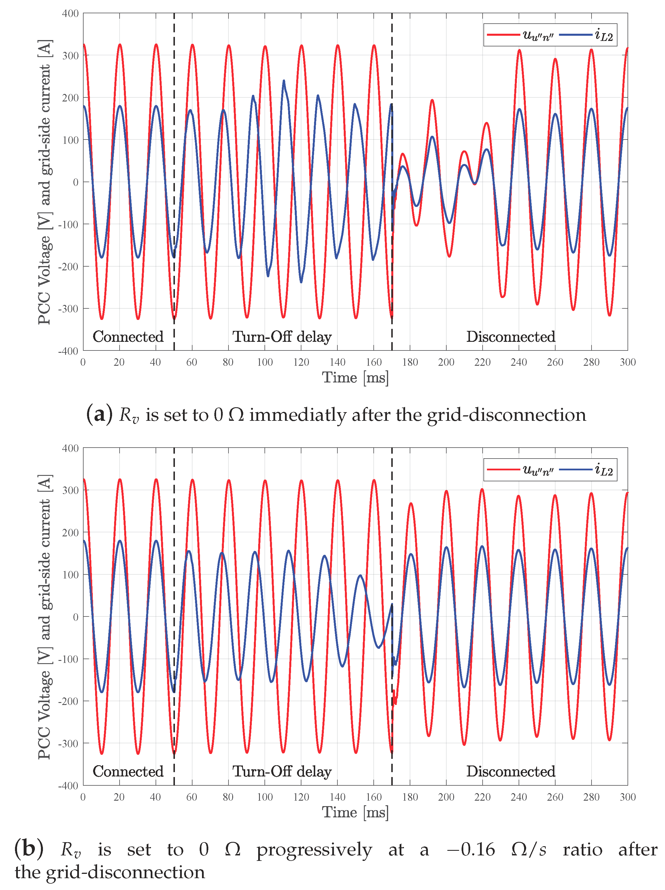
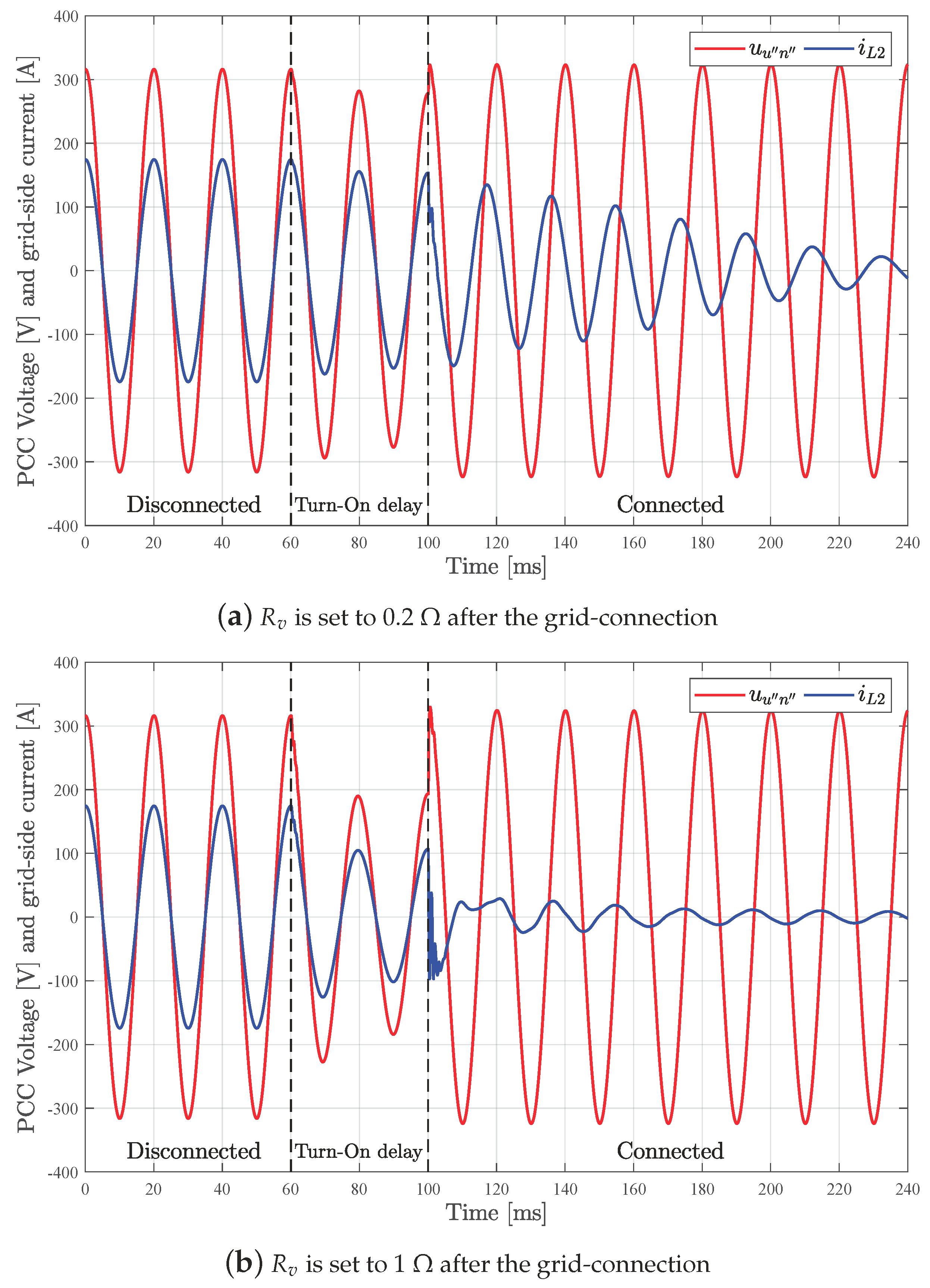
4.2.1. Virtual Resistance Effect on the Transference

For this analysis, a transference is forced to 50 ms time. A main switch to segregate the mains from the microgrid with a turn-on/off delay of 40/120 ms has been assumed.
In Figure 9, the effect of the R v value on the voltage u u n and the delivered current i L 2 can be observed when a grid-connected to grid-disconnected transference takes place. In the initial situation, P u * is set at 30 kW before t = 50 ms and a local load of 1.81 Ω is connected at any time. The use of an initial R v allows for smoothing the transference in terms of voltage and currents.
In Figure 10, the effect of the R v value on the voltage u u n and the delivered current i L 2 can be observed when a reconnection transference takes place. In this case, in the initial situation, a load of 1.81 Ω is connected and maintained after the reconnection. No P Q references are considered in this case. As in the disconnection case, the use of an initial R v smooths the transference in terms of voltage and currents. The use of high R v values helps to extinguish the i L 2 current faster but creates a voltage dip. However, this virtual resistance allows for making the system less sensitive due to interfacing with a virtual current limiter during the reconnection process. Then, a trade-off R v value has to be used when the reconnection occurs. According to the mentioned reasons, an R v equal to 1 Ω is suggested as a proper compromise value, also used in the experimental validation in Section 4.3.1.

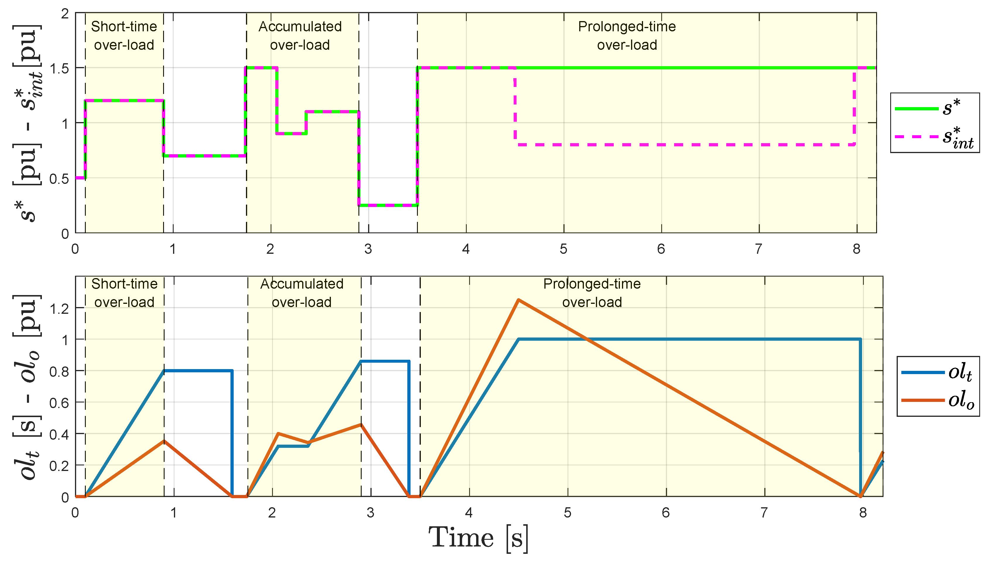
4.2.2. Power Over-Load Supervisor

Figure 11 shows the behaviour of the power over-load supervisor strategy presented in Figure 6. In Figure 11, s * refers to the power set-point received from any external manager, while s i n t * , represents the inner reference managed by the mentioned over-load supervisor strategy. Note that the current tracking is supposed to operate properly, as it is illustrated in Section 4.
In Figure 11, three different study cases framed in yellow can be observed. The first one refers to a short-time over-load demand. The second one accumulates two over-load queries. Finally, the third one evaluates a prolonged over-load target. The maximum over-load time, T m a x o l , is set to 1 s.
Regarding the short-time scenario, when s * is higher than 1, the o l t and o l o values increase. When s is lower than 1, the o l t time is held while o l o decreases progressively according to Equation (1). In this sense, the generated thermal stress on the cooling system is limited. This situation is exemplified in the accumulated over-load region. Although the set-point s is reduced transiently, the o l t time continues increasing due to not achieving o l o equal to zero. Lastly, for a prolonged-time, an over-load region can be observed as to how the over-load strategy limits the inner set-point s i n t * to 0.8 [pu]. This situation is produced when o l t reaches a pre-configured T m a x o l and remains unaltered until the o l o reaches zero. Note that the maximum over-load time, T m a x o l , can be configured for each phase according to any specific design of the cooling system. Thus, the 1 s previously selected is just an example.

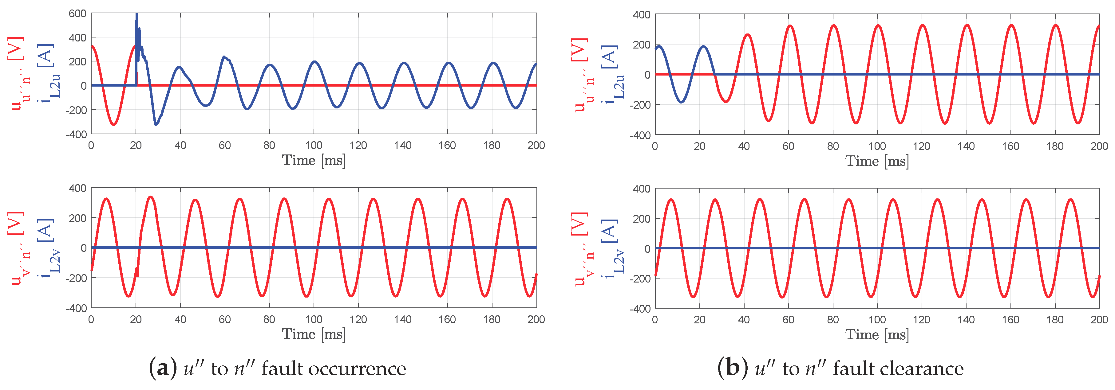
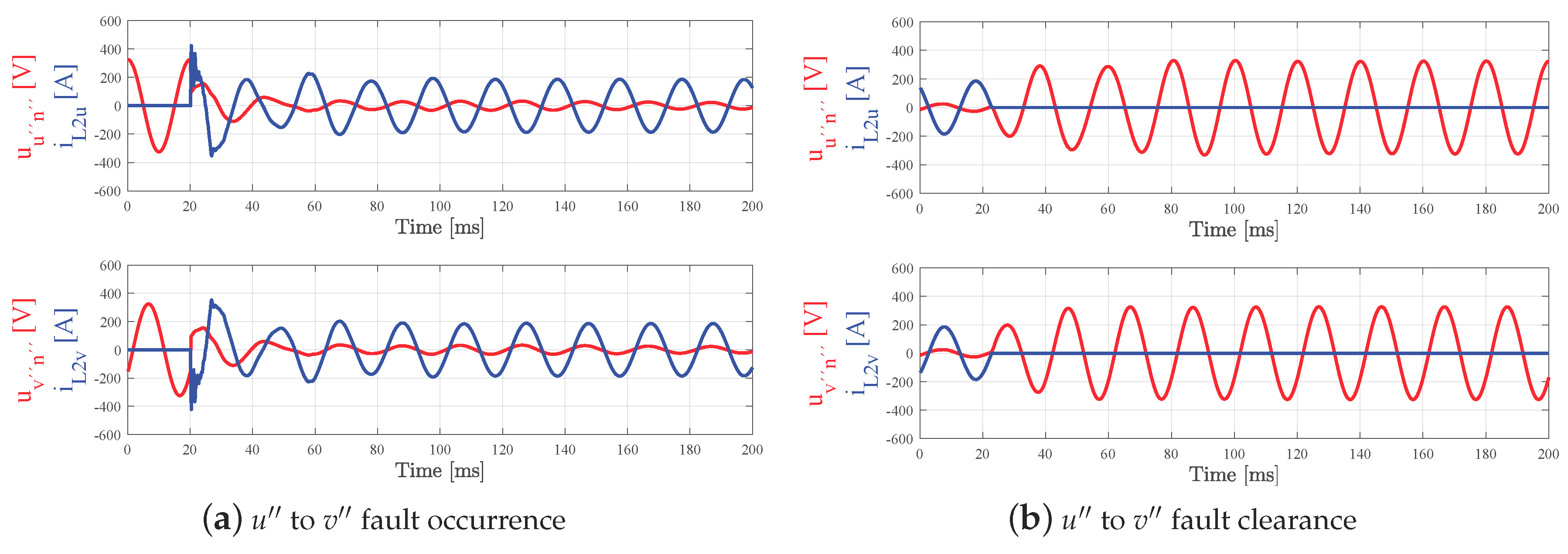
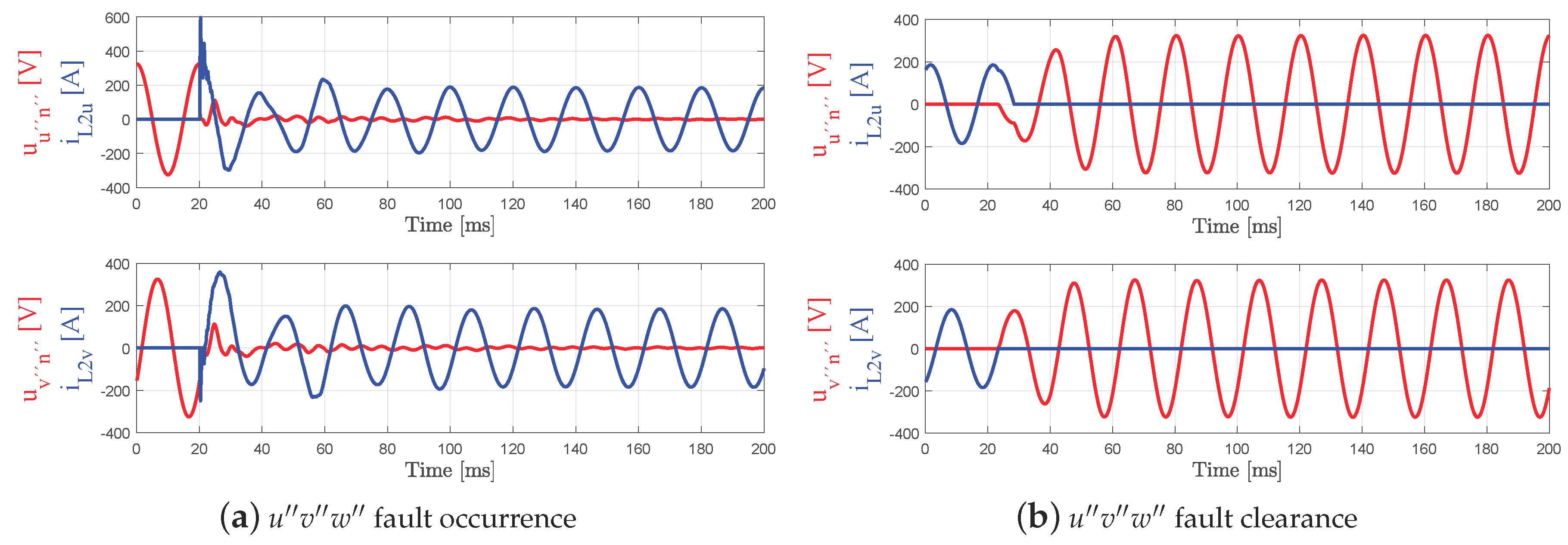
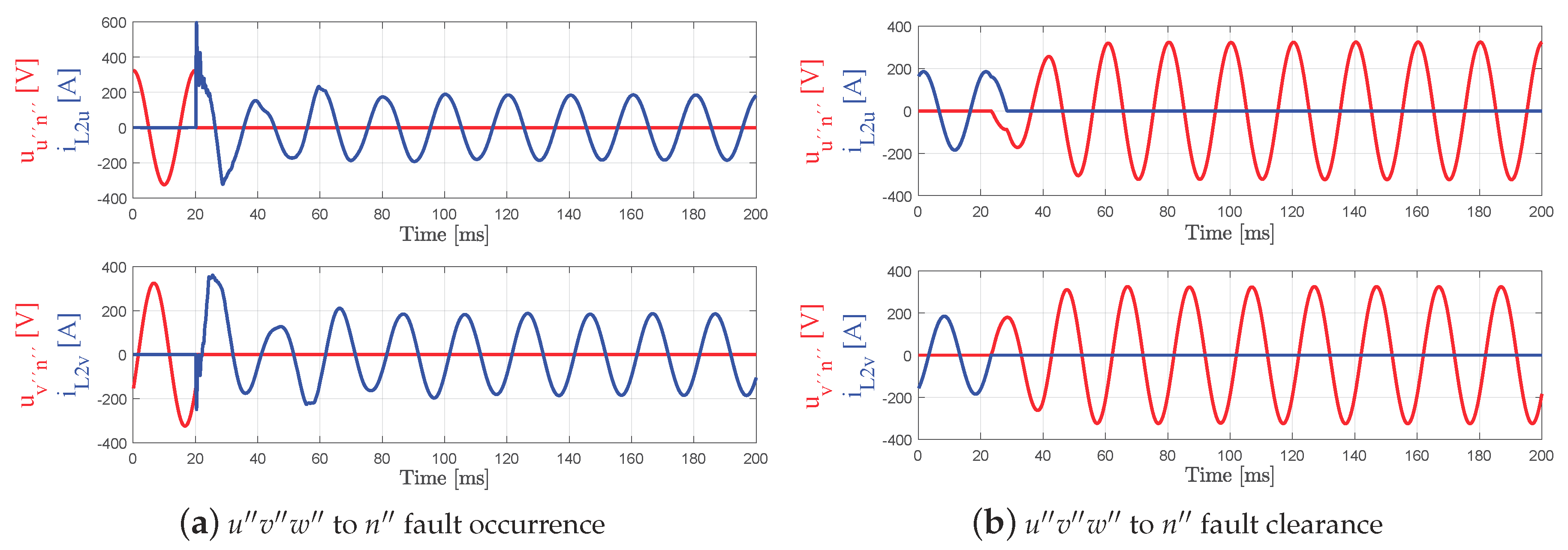
4.2.3. Short-Circuit Proof Algorithm

Scenario 1—Phase to neutral short-circuit. Figure 12a,b show the behaviour of the voltage and current of phases u and v when a unipolar u n short-circuit is generated and recovered, respectively. It can be seen that the voltage goes to zero when the fault appears maintaining the current limited with a sinusoidal waveform. When the fault is recovered, the voltage increases progressively without producing any problematic over-voltage. In both cases, the time response is less than 60 ms.
Scenario 2—Phase to phase short-circuit. Figure 13a,b show the behaviour of the voltage and current of phases u and v when a bipolar u v short-circuit is generated and recovered. It can be deduced i L 2 u = i L 2 v and u u n = u v n , as can be also observed in Figure 13b. This case is particularly interesting because, although the current is properly managed in the steady-state, it can be seen that the voltage does not go to zero after the fault.
When the fault occurs, it is possible that, in one of the two involved phases, its voltage control action, PRHC u output, plus the short-circuit current, i L 2 , adds up to more than in the other case (see Figure 7b). The phase with more errors rapidly produces a k 1 gain that moves from one to zero. As the other phase operates with higher k 1 values, it starts to control the current without necessarily a k 1 gain equal to zero. This means without the correspondent phase-to-neutral voltage equal to zero. When the fault is recovered, the voltage increases progressively without producing any problematic over-voltage. As in the unipolar case, the transients are resolved in less than 2–3 grid cycles.
Scenarios 3–4—Three-phase short-circuit and Three-phase to neutral short-circuit. Figure 14 and Figure 15 show the behaviour of the voltage and current of phases u and v when a tripolar between phases or a tetrapolar short-circuit is enforced and recovered, respectively. As in the previously studied cases, the behaviour of the current and voltage follows similar time responses.

4.3. Experimental Results

This section is divided into three subsections to validate the suggested proposals along the paper and check the simulation results presented in the previous section.

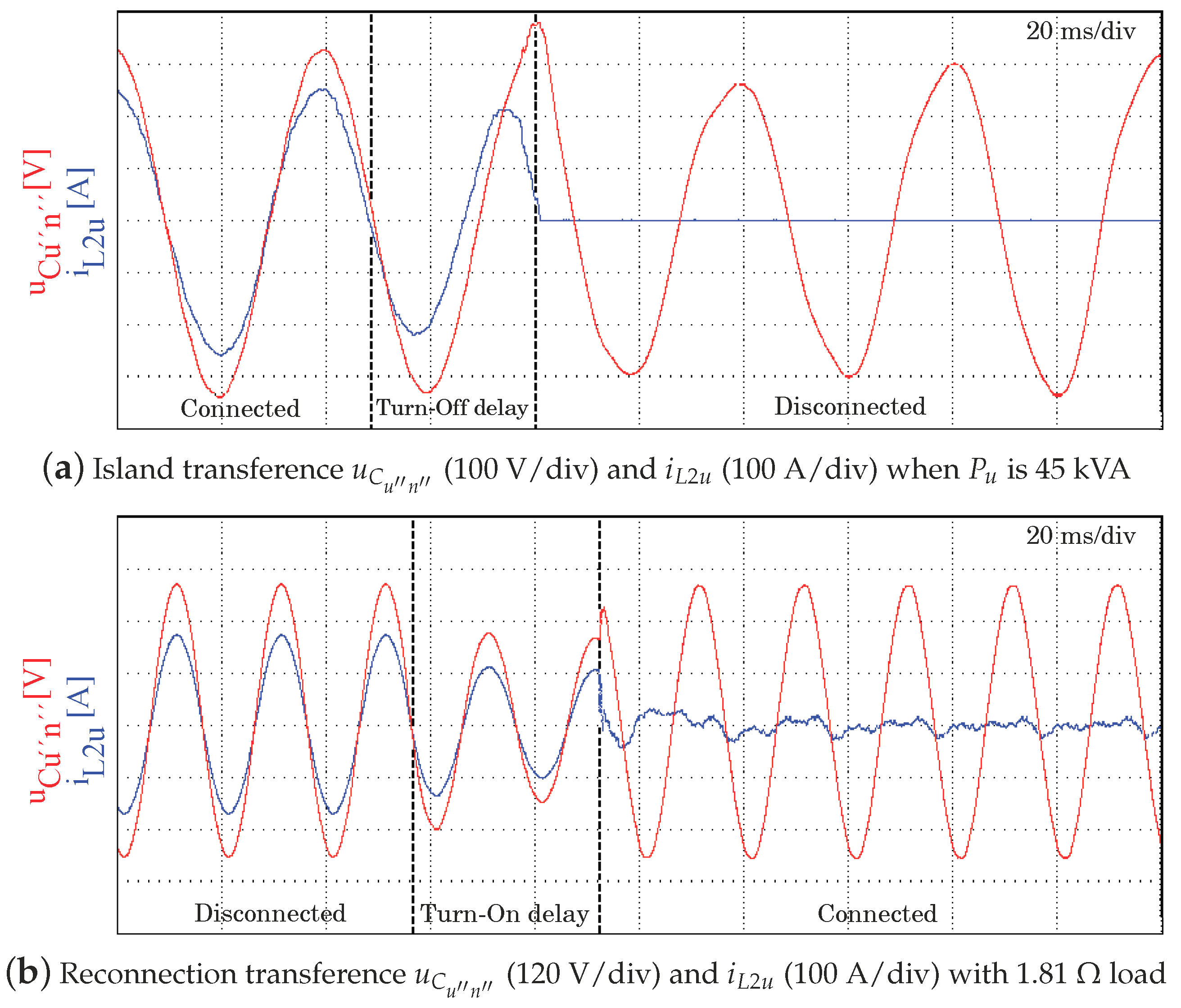
4.3.1. Virtual Resistance Effect on the Transference

In Section 4.2.1, the theoretical effectiveness of the virtual resistance algorithm to smooth the transference between grid-(dis)connected modes was demonstrated by simulations. For the experimental validation, only the R v value of 1 Ω has been used when the reconnection occurs, as detailed in Section 4.2.1. Figure 16 shows the experimental results for two scenarios, grid-connected to grid-disconnected and vice versa. A load of 1.81 Ω has been considered.
Scenario 1—Transition from grid-connected to grid-disconnected at maximum power without local loads. Phase u is delibering 45 kW while the other two phases are with null P Q requests. Then, a non-intentional disconnection to start operating in grid-disconnected is done. Figure 16a shows the proper behaviour of the voltage, creating a short-duration dip that meets the ITI curve. After the transition, the delivered current goes to zero and the voltage of the microgrid is maintained.
Scenario 2—Transition from grid-disconnected to grid-connected with load. A reconnection procedure is intentionally done with a high current local load. Figure 16b allows for observing that, after the reconnection, the u C u n voltage suffers a dip during two cycles, but the current i L 2 is extinguished just after the reconnection is finished. The experimental results are close to the simulation shown in Figure 10b, validating the exposed method.
In both cases, the PCC voltage suffers an alteration, the transition from grid-disconnected to the grid-connected mode being more critical. However, in both cases, the voltage alterations are resolved by control in less than 40 ms, meeting the ITI curve requirements. This trade-off permits a safe system connection even in weak grids while complying the regulation requirements.

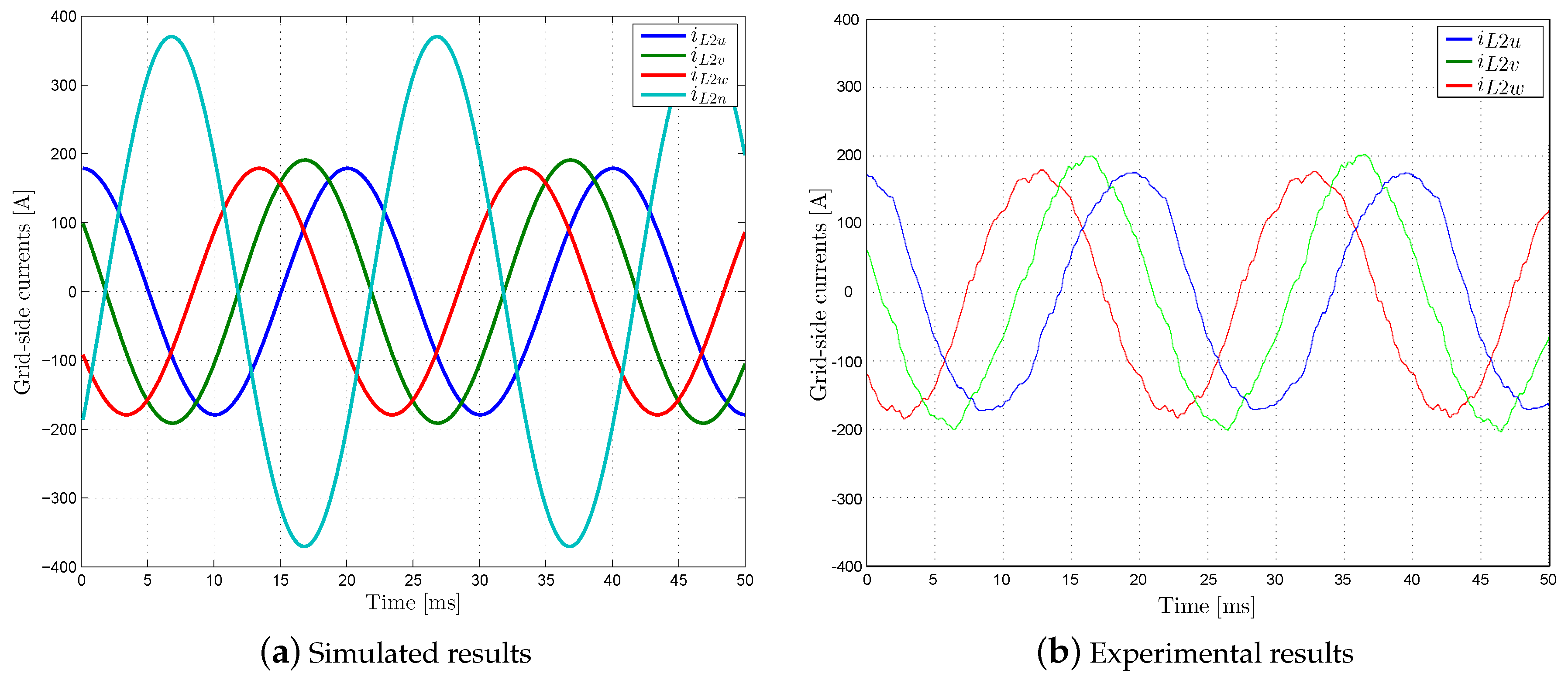
4.3.2. Four Quadrant Control Capability

The objective of this section is showing the capability of the inverter to control unbalanced phase currents as mentioned in Section 1 and required for the proper use of the over-load supervisor strategy suggested in Section 4.2.2. In this scenario, the inverter is operating in grid-connected mode with rated (non over-loaded) unbalanced P Q set-points. The set-points per phase are P u = P w = 30 kW, P v = −30 kW and Q u v w all nulls. Figure 17 shows that the inverter is able to synthesize non-balanced currents from non-balanced P Q references.
Figure 17a shows a simulation of the expected active phase and neutral wire output currents, respectively. Figure 17b presents the captured oscilloscope active currents. It is demonstrated that there is no problem to track unbalanced P Q set-points. Thus, it is possible to ensure that if an over-load supervisor manages the inner converter references, called s i n t * in Figure 11, the inverter can provide autonomous over-load capability per phase.

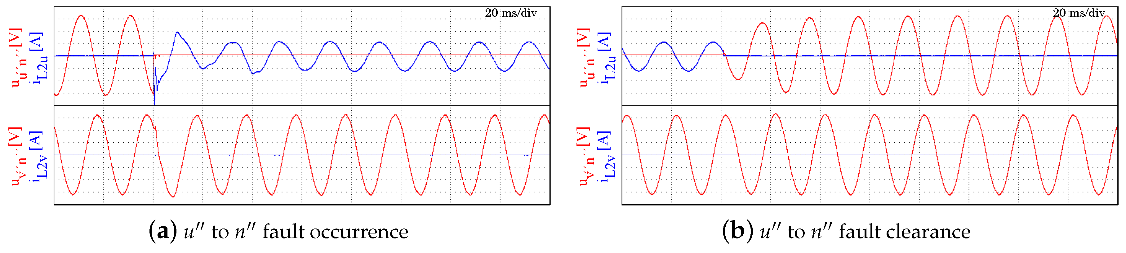
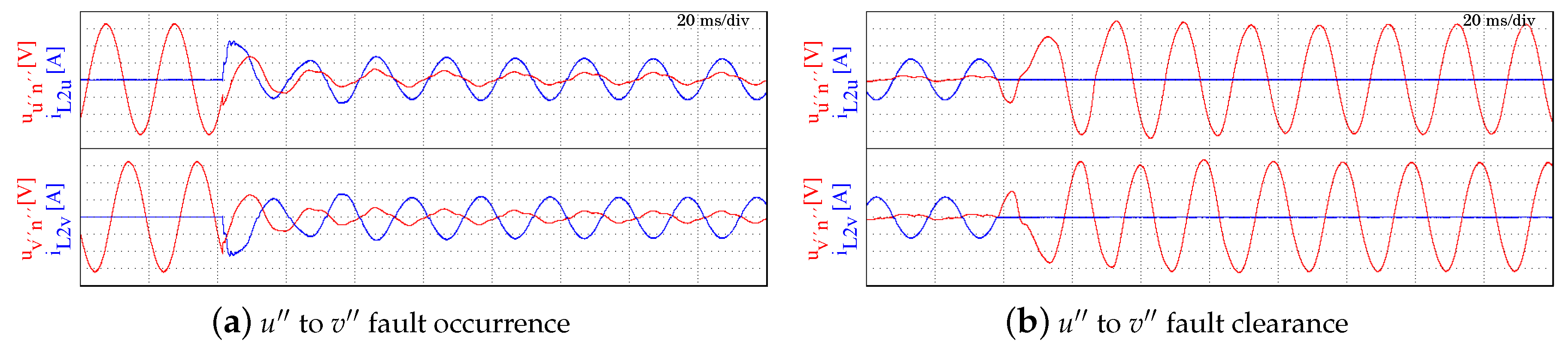
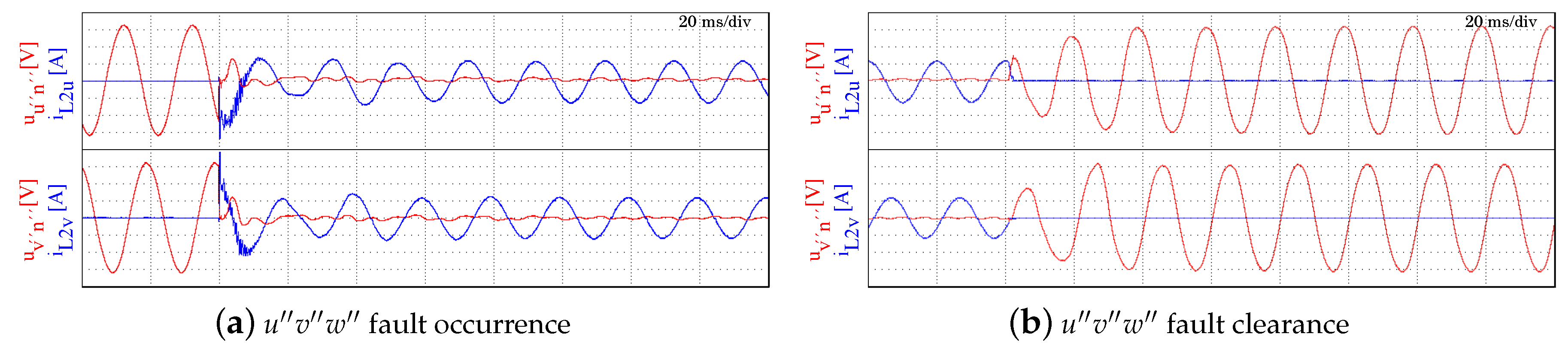
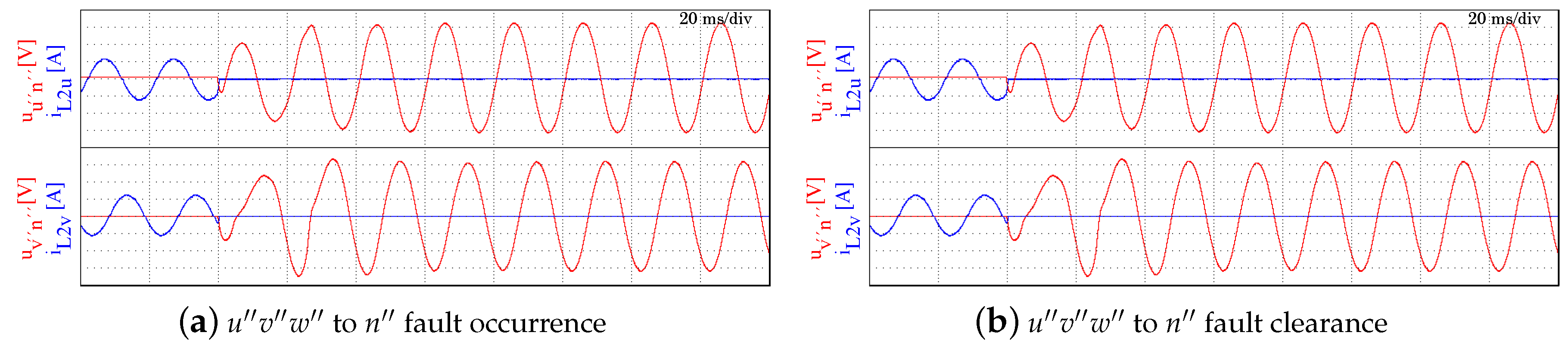
4.3.3. Short-Circuit Proof Algorithm

In this section, the four scenarios simulated in Section 4.2.3 are reproduced in the experimental platform to validate the real capabilities of the proposed fault current limitation strategy. In the following lines, it is demonstrated that the time response for the fault current limitation action and voltage recovery offers superior time responses than in the current literature [38,39,40].
Scenario 1—Phase to neutral short-circuit. Figure 18 shows the behaviour of the voltage and current of phases u and v when unipolar u n is produced. Analogously with Figure 12a, it can be seen in Figure 18a that, when the fault appears, the control maintains the current limited with a sinusoidal waveform presenting a minor oscilation that is resolved in less than 30 ms. Figure 12b shows the system behaviour when the fault is cleared, recovering the nominal voltage value progresively in less than two grid cicles, in the same way as the simulation reproduced in Figure 12b.
Scenario 2—Phase to phase short-circuit. Figure 19 shows the behaviour of the voltage and current of phases u and v when a bipolar u v short-circuit is generated and recovered, analogous to simulations shown in Figure 13. In Figure 19a, it can be seen that the initial transient of current u and v is less than two times the maximum current, achieving steady-state values in less than 30 ms. When the fault is recovered, the voltage increases progressively achieving the steady-state in less than 40 ms as shown in Figure 19b.
Scenarios 3–4—Three-phase short-circuit and Three-phase to neutral short-circuit. Figure 20 and Figure 21 show the behaviour of the voltage and current of phases u and v when a tripolar and tretrapolar fault is produced. As in the simulated cases shown in Figure 14 and Figure 15, the control algorithm limits the fault current in the expected time, being less than 40 ms. The fault recovery is also achieved rapidly, in less than two grid cycles.

5. Conclusions

This paper has presented two control strategies to achieve a fast and proper fault current limitation for four wire microgrid inverters. Both strategies are supported by a dynamic virtual resistance mechanism that allows for a fast transference between grid-(dis)connected operation modes.
Concerning the AC side inverter operation, a seamless transference between grid-(dis)connected modes has been ensured obtaining short transients, below three grid cycles. For this purpose, a combination of an AC droop control based on dynamic phasors when grid-connected and master voltage/frequency control when grid-disconnected has been proposed. It has been demonstrated not only that this is a valid option to maintain the voltage behaviour between operation modes, but also it is able to make the grid-disconnected operation independent from the AC droop control loop constraints. Thus, the transients in grid-disconnected mode are only limited by the settling time of the voltage control loop. Furthermore, a varying virtual resistance is suggested for achieving the mentioned seamless transference, disabling the resistance value progressively when entering in grid-disconnected operation. It has been illustrated that the proper selection of the steady-state virtual resistance and the used variation ratio helps to avoid voltage sags in the transient phase between the operation modes, allows for being less sensitive to the reconnection process and, finally, provides a predominant resistive behaviour for the grid-connected operation.
An over-load manager supervisor strategy based on thermal criteria has been introduced. This over-load strategy provides an increase in managing flexibility to a microgrid inverter in a grid-connected mode. The over-size challenge is then delegated to higher current switching devices, a not really cost sensitive component today in power converters. Thus, if the cooling system has enough thermal time lag, it is possible to obtain over-load skills in which the available over-load currents are managed by the proposed strategy. In case of prolonged over-load, the situation is detected and the inverter simply delivers a percentage of the nominal current to relieve the accumulated thermal stress.
Finally, a short-circuit proof strategy is introduced as a fault current limiter and voltage regulator. This short-circuit proof strategy is validated though unipolar, bipolar, tripolar and tetrapolar pure short-circuits. As the control in grid-disconnected mode is only based on voltage and current control loops, the suggested strategy only considers voltage and current, but not power. The strategy is mainly based on computing the rms value of the delivered current. Then, the current and voltage can be quickly adapted to handle the fault occurrence and clearance. This is done maintaining sinusoidal waveforms in both cases by a simple calculation of two proportional factors and the use of a filter. In this sense, the time response of protective devices will be affected minimally. The time response has been a priority in this paper, obtaining fault current limitation and voltage regulation in the order of two–three grid cycles even considering low impedance short-circuits, a superior capability compared to similar literature.
The feasibility of the proposed converter has been demonstrated not only at control level by simulation using Matlab/Simulink but also experimentally at a CENER-ATENEA four-wire microgrid.

Author Contributions

Conceptualization, D.H.-P., M.P.-G. and C.C.-A.; Software, D.H.-P., M.P.-G. and C.C.-A.; Validation, M.S., D.R. and M.A.; Formal Analysis, D.H.-P.; Investigation, D.H.-P., M.P.-G. and C.C.-A.; Methodology, D.M.-M.; Resources, M.S., D.R. and M.A.; Writing—Original Draft Preparation, D.H.-P.; Writing—Review D.H.-P., C.C.-A.

Funding

This research received no external funding.

Conflicts of Interest

The authors declare no conflict of interest.

References

  1. Hatziargyriou, N. The Microgrids Concept. In Microgrids: Architectures and Control; IEEE: Piscataway, NJ, USA, 2014. [Google Scholar] [CrossRef]
  2. Bevrani, H.; Watanabe, M.; Mitani, Y. Microgrid Control: Concepts and Classification. In Power System Monitoring and Control; IEEE: Piscataway, NJ, USA, 2014. [Google Scholar] [CrossRef]
  3. Hartono, B.S.; Budiyanto, Y.; Setiabudy, R. Review of microgrid technology. In Proceedings of the 2013 International Conference on QiR (Quality in Research), Yogyakarta, Indonesia, 25–28 June 2013; pp. 127–132. [Google Scholar] [CrossRef]
  4. Cecati, C.; Khalid, H.A.; Tinari, M.; Adinolfi, G.; Graditi, G. DC nanogrid for renewable sources with modular DC–DC LLC converter building block. IET Power Electron. 2017, 10, 536–544. [Google Scholar] [CrossRef]
  5. Zubieta, L.E. Are Microgrids the Future of Energy?: DC Microgrids from Concept to Demonstration to Deployment. IEEE Electrif. Mag. 2016, 4, 37–44. [Google Scholar] [CrossRef]
  6. Guerrero, J.; Vasquez, J.; Teodorescu, R. Hierarchical control of droop controlled DC and AC microgrids. In Proceedings of the the 35th Annual Conference of the IEEE Industrial Electronics Society, Porto, Portugal, 3–5 November 2009. [Google Scholar]
  7. Guo, F.; Wen, C.; Mao, J.; Song, Y. Distributed Secondary Voltage and Frequency Restoration Control of Droop-Controlled Inverter-Based Microgrids. IEEE Trans. Ind. Electron. 2015, 62, 4355–4364. [Google Scholar] [CrossRef]
  8. Che, L.; Shahidehpour, M.; Alabdulwahab, A.; Al-Turki, Y. Hierarchical Coordination of a Community Microgrid With AC and DC Microgrids. IEEE Trans. Smart Grid 2015, 6, 3042–3051. [Google Scholar] [CrossRef]
  9. Dehkordi, N.M.; Sadati, N.; Hamzeh, M. Robust tuning of transient droop gains based on Kharitonov’s stability theorem in droop-controlled microgrids. IET Gener. Transm. Distrib. 2018, 12, 3495–3501. [Google Scholar] [CrossRef]
  10. Han, Y.; Shen, P.; Zhao, X.; Guerrero, J.M. Control Strategies for Islanded Microgrid Using Enhanced Hierarchical Control Structure With Multiple Current-Loop Damping Schemes. IEEE Trans. Smart Grid 2017, 8, 1139–1153. [Google Scholar] [CrossRef]
  11. He, J.; Li, Y.W.; Blaabjerg, F. Flexible Microgrid Power Quality Enhancement Using Adaptive Hybrid Voltage and Current Controller. IEEE Trans. Ind. Electron. 2014, 61, 2784–2794. [Google Scholar] [CrossRef]
  12. Lim, K.; Choi, J. PR control based cascaded current and voltage control for seamless transfer of microgrid. In Proceedings of the 2015 IEEE 2nd International Future Energy Electronics Conference (IFEEC), Taipei, Taiwan, 1–4 November 2015; pp. 1–6. [Google Scholar] [CrossRef]
  13. Rahmani-Andebili, M. Cooperative Distributed Energy Scheduling in Microgrids. In Electric Distribution, Network Management and Control; Springer: Singapore, 2018; pp. 235–254. [Google Scholar] [CrossRef]
  14. Han, Y.; Zhang, K.; Li, H.; Coelho, E.A.A.; Guerrero, J.M. MAS-Based Distributed Coordinated Control and Optimization in Microgrid and Microgrid Clusters. A Comprehensive Overview. IEEE Trans. Power Electron. 2018, 33, 6488–6508. [Google Scholar] [CrossRef]
  15. Marzband, M.; Sumper, A.; Dominguez-Garcia, J.L.; Gumara-Ferreta, R. Experimental validation of a real time energy management system for microgrids in islanded mode using a local day-ahead electricity market and MINLP. Energy Convers. Manag. 2013, 76, 314–322. [Google Scholar] [CrossRef]
  16. Marzband, M.; Azarinejadian, F.; Savaghebi, M.; Pouresmaeil, E.; Guerrero, J.M.; Lightbody, G. Smart transactive energy framework in grid-connected multiple home microgrids under independent and coalition operations. Renew. Energy 2018, 126, 95–106. [Google Scholar] [CrossRef]
  17. Marzband, M.; Fouladfar, M.H.; Akoredei, M.F.; Pouresmaeil, E.; Lightbody, G. Framework for Smart Transactive Energy in Home-Microgrids Considering Coalition Formation and Demand Side Management. Sustain. Cities Soc. 2018, 40, 136–154. [Google Scholar] [CrossRef]
  18. Tavakoli, M.; Shokridehaki, F.; Marzband, M.; Godinac, R.; Pouresmaeil, E. A two stage hierarchical control approach for the optimal energy management in commercial building microgrids based on local wind power and PEVs. Sustain. Cities Soc. 2018, 41, 332–340. [Google Scholar] [CrossRef]
  19. Hatziargyriou, N. Microgrid Protection. In Microgrids: Architectures and Control; IEEE: Piscataway, NJ, USA, 2014. [Google Scholar] [CrossRef]
  20. Sharkh, S.M.; Abu-Sara, M.A.; Orfanoudakis, G.I.; Hussain, B. Microgrid Protection. In Power Electronic Converters for Microgrids; IEEE: Piscataway, NJ, USA, 2014. [Google Scholar] [CrossRef]
  21. Carpio-Huayllas, T.E.D.; Ramos, D.S.; Vasquez-Arnez, R.L. Microgrid transition to islanded modes: Conceptual background and simulation procedures aimed at assessing its dynamic performance. In Proceedings of the Transmission and Distribution Conference and Exposition (T D), Orlando, FL, USA, 7–10 May 2012; pp. 1–6. [Google Scholar] [CrossRef]
  22. Heredero-Peris, D.; Chillón-Antón, C.; Pagès-Giménez, M.; Gross, G.; Montesinos-Miracle, D. Implementation of grid-connected to/from off-grid transference for micro-grid inverters. In Proceedings of the IECON 2013—39th Annual Conference of the IEEE Industrial Electronics Society, Vienna, Austria, 10–13 November 2013; pp. 840–845. [Google Scholar] [CrossRef]
  23. Liu, Z.; Liu, J. Unified control based seamless transfer of microgrids. In Proceedings of the 2015 9th International Conference on Power Electronics and ECCE Asia (ICPE-ECCE Asia), Seoul, Korea, 1–5 June 2015; pp. 1477–1482. [Google Scholar] [CrossRef]
  24. Shen, Z.J. Ultrafast Solid-State Circuit Breakers: Protecting Converter-Based ac and dc Microgrids Against Short Circuit Faults [Technology Leaders]. IEEE Electrif. Mag. 2016, 4, 70–72. [Google Scholar] [CrossRef]
  25. Laaksonen, H.J. Protection Principles for Future Microgrids. IEEE Trans. Power Electron. 2010, 25, 2910–2918. [Google Scholar] [CrossRef]
  26. Zhang, J.; Wu, P.; Hong, J. Control strategy of microgrid inverter operation in Grid-connected and Grid-disconnected modes. In Proceedings of the International Conference on Electric Information and Control Engineering (ICEICE), Wuhan, China, 25–27 March 2011; pp. 1257–1260. [Google Scholar] [CrossRef]
  27. Shan, W.C.; Lin, L.X.; Li, G.; Wei, L.Y. A seamless operation mode transition control strategy for a microgrid based on master–slave control. In Proceedings of the 2012 31st Chinese Control Conference, Hefei, China, 25–27 July 2012; pp. 6768–6775. [Google Scholar]
  28. Brabandere, K.D. Voltage and Frequency Droop Control in Low Voltage Grids by Distributed Generators with Inverter Front-End. Ph.D. Thesis, Katholieke Universiteit Leuven, Leuven, Belgium, 2006. [Google Scholar]
  29. Wessels, C.; Dannehl, J.; Fuchs, F. Active damping of LCL-filter resonance based on virtual resistor for PWM rectifiers; stability analysis with different filter parameters. In Proceedings of the 2008 IEEE Power Electronics Specialists Conference, Rhodes, Greece, 15–19 June 2008; pp. 3532–3538. [Google Scholar] [CrossRef]
  30. Kim, J.; Guerrero, J.; Rodríguez, P.; Teodorescu, R.; Nam, K. Mode Adaptive Droop Control with Virtual Output Impedances for an Inverter-Based Flexible AC Microgrid. IEEE Trans. Power Electron. 2011, 26, 689–701. [Google Scholar] [CrossRef]
  31. Guo, X.; Lu, Z.; Wang, B.; Sun, X.; Wang, L.; Guerrero, J. Dynamic Phasors-Based Modeling and Stability Analysis of Droop-Controlled Inverters for Microgrid Applications. IEEE Trans. Smart Grid 2014, 5, 2980–2987. [Google Scholar] [CrossRef] [Green Version]
  32. Bayindir, R.; Irmak, E.; Issi, F.; Guler, N. Short-circuit fault analysis on microgrid. In Proceedings of the 2015 International Conference on Renewable Energy Research and Applications (ICRERA), Palermo, Italy, 22–25 November 2015; pp. 1248–1252. [Google Scholar] [CrossRef]
  33. Almutairy, I. A review of coordination strategies and techniques for overcoming challenges to microgrid protection. In Proceedings of the 2016 Saudi Arabia Smart Grid (SASG), Jeddah, Saudi Arabia, 6–8 December 2016; pp. 1–4. [Google Scholar] [CrossRef]
  34. Lai, X.; Liu, F.; Deng, K.; Gao, Q.; Zha, X. A short-circuit current calculation method for low-voltage DC microgrid. In Proceedings of the 2014 International Power Electronics and Application Conference and Exposition, Shanghai, China, 5–8 November 2014; pp. 365–371. [Google Scholar] [CrossRef]
  35. Ouaida, R.; Berthou, M.; Tournier, D.; Depalma, J. State of art of current and future technologies in current limiting devices. In Proceedings of the 2015 IEEE First International Conference on DC Microgrids (ICDCM), Atlanta, GA, USA, 7–10 June 2015; pp. 175–180. [Google Scholar] [CrossRef]
  36. Balasreedharan, S.S.; Thangavel, S. An adaptive fault identification scheme for DC microgrid using event based classification. In Proceedings of the 2016 3rd International Conference on Advanced Computing and Communication Systems (ICACCS), Coimbatore, India, 22–23 January 2016; Volume 1, pp. 1–7. [Google Scholar] [CrossRef]
  37. Cairoli, P.; Rodrigues, R.; Zheng, H. Fault current limiting power converters for protection of DC microgrids. In Proceedings of the SoutheastCon 2017, Charlotte, NC, USA, 30 March–2 April 2017; pp. 1–7. [Google Scholar] [CrossRef]
  38. Pei, X.; Chen, Z.; Wang, S.; Kang, Y. Overcurrent protection for inverter-based distributed generation system. In Proceedings of the 2015 IEEE Energy Conversion Congress and Exposition (ECCE), Montreal, QC, Canada, 20–24 September 2015; pp. 2328–2332. [Google Scholar] [CrossRef]
  39. Babqi, A.J.; Etemadi, A.H. MPC-based microgrid control with supplementary fault current limitation and smooth transition mechanisms. IET Gener. Transm. Distrib. 2017, 11, 2164–2172. [Google Scholar] [CrossRef]
  40. Beheshtaein, S.; Savaghebi, M.; Guerrero, J.M.; Cuzner, R.; Vasquez, J.C. A secondary-control based fault current limiter for four-wire three phase inverter-interfaced DGs. In Proceedings of the IECON 2017—43rd Annual Conference of the IEEE Industrial Electronics Society, Beijing, China, 29 October–1 November 2017; pp. 2363–2368. [Google Scholar] [CrossRef]
  41. Rahmatian, M.; Sanjari, M.J.; Gholami, M.; Gharehpetian, G.B. Optimal control of distribution line series compensator in microgrid considering fault current limitation function. In Proceedings of the 2012 17th Conference on Electrical Power Distribution, Tehran, Iran, 2–3 May 2012; pp. 1–5. [Google Scholar]
  42. Sadeghkhani, I.; Golshan, M.E.H.; Mehrizi-Sani, A.; Guerrero, J.M. Low-voltage ride-through of a droop-based three-phase four-wire grid-connected microgrid. IET Gener. Transm. Distrib. 2018, 12, 1906–1914. [Google Scholar] [CrossRef]
  43. Li, Y.; Vilathgamuwa, D.M.; Loh, P.C. Microgrid power quality enhancement using a three-phase four-wire grid-interfacing compensator. IEEE Trans. Ind. Appl. 2005, 41, 1707–1719. [Google Scholar] [CrossRef]
  44. Kim, G.H.; Hwang, C.; Jeon, J.H.; Byeon, G.S.; Ahn, J.B.; Jo, C.H. Characteristic analysis of three-phase four-leg inverter based load unbalance compensator for stand-alone microgrid. In Proceedings of the 2015 9th International Conference on Power Electronics and ECCE Asia (ICPE-ECCE Asia), Seoul, Korea, 1–5 June 2015; pp. 1491–1496. [Google Scholar] [CrossRef]
  45. Liu, Y.-H.; Yang, J.; Li, H.; Wang, C. The research of three phase four wire active power filter on small independent micro-grid. In Proceedings of the 2016 China International Conference on Electricity Distribution (CICED), Xi’an, China, 10–13 August 2016; pp. 1–4. [Google Scholar] [CrossRef]
  46. Lee, W.; Han, B.M.; Cha, H. Battery ripple current reduction in a three-phase interleaved dc-dc converter for 5 kW battery charger. In Proceedings of the 2011 IEEE Energy Conversion Congress and Exposition, Phoenix, AZ, USA, 17–22 September 2011; pp. 3535–3540. [Google Scholar] [CrossRef]
  47. Khosroshahi, A.; Abapour, M.; Sabahi, M. Reliability Evaluation of Conventional and Interleaved DC–DC Boost Converters. IEEE Trans. Power Electron. 2015, 30, 5821–5828. [Google Scholar] [CrossRef]
  48. Llonch-Masachs, M.; Heredero-Peris, D.; Montesinos-Miracle, D.; Rull-Duran, J. Understanding the three and four-leg inverter Space Vector. In Proceedings of the 2016 18th European Conference on Power Electronics and Applications (EPE’16 ECCE Europe), Karlsruhe, Germany, 5–9 September 2016; pp. 1–10. [Google Scholar] [CrossRef]
  49. Heredero-Peris, D.; Pagès-Giménez, M.; Montesinos-Miracle, D. Inverter design for four-wire microgrids. In Proceedings of the 2015 17th European Conference on Power Electronics and Applications (EPE’15 ECCE-Europe), Geneva, Switzerland, 8–10 September 2015; pp. 1–10. [Google Scholar] [CrossRef]
  50. Rivas, H.A.; Bergas, J. Frequency Determination in a Single-Phase Voltage Signal using Adaptative Notch Filters. In Proceedings of the 2007 9th International Conference on Electrical Power Quality and Utilisation, Barcelona, Spain, 9–11 October 2007; pp. 1–7. [Google Scholar] [CrossRef]
  51. Yepes, A.G. Digital Resonant Current Controllers for Voltage Source Converters. Ph.D. Thesis, Universidad de Vigo, Pontevedra, Spain, 2011. [Google Scholar]
  52. Rodríguez, F.; Bueno, E.; Aredes, M.; Rolim, L.; Neves, F.; Cavalcanti, M. Discrete-time implementation of second order generalized integrators for grid converters. In Proceedings of the 2008 34th Annual Conference of IEEE Industrial Electronics, Orlando, FL, USA, 10–13 November 2008; pp. 176–181. [Google Scholar]
  53. Balaras, C.A. The role of thermal mass on the cooling load of buildings. An overview of computational methods. Energy Build. 1996, 24, 1–10. [Google Scholar] [CrossRef] [Green Version]
  54. Mjallal, I.; Farhat, H.; Hammoud, M.; Ali, S.; Assi, I. Improving the Cooling Efficiency of Heat Sinks through the Use of Different Types of Phase Change Materials. Technologies 2018, 6, 5. [Google Scholar] [CrossRef]
  55. ITI (CBEMA) Curve Application Note; Techreport; Information Technology Industry Council: Washington, DC, USA, 2000.
Figure 1. Diagram of the ATENEA microgrid at The National Renewable Energy Centre (CENER). A blue dashed box indicates the two possible direct current–alternating current (DC–AC) converters that can implement the proposed strategies.
Applsci 08 01725 g001
Figure 2. Scheme of the full direct current–direct current (DC–DC) and DC–AC proposed converter.
Applsci 08 01725 g002
Figure 3. Interleaved DC–DC converter control schemes. Proportional Integral (PI).
Applsci 08 01725 g003
Figure 4. The virtual resistance R v operation.
Applsci 08 01725 g004
Figure 5. Resistive case power close loop scheme under dynamic phasors.
Applsci 08 01725 g005
Figure 6. Scheme of the power over-load supervisor algorithm.
Applsci 08 01725 g006
Figure 7. Control schemes of the sinusoidal wave short-circuit proof algorithm.
Applsci 08 01725 g007
Figure 8. Converter installed in the ATENEA experimental microgrid.
Applsci 08 01725 g008
Figure 9. R v (0.2 Ω initially) effect during grid-connected to grid-disconnected transference at t = 50 ms .
Applsci 08 01725 g009
Figure 10. R v (0 Ω initially) effect during grid-disconnected to grid-connected transference at t = 50 ms .
Applsci 08 01725 g010
Figure 11. Example of the power over-load supervisor algorithm behaviour.
Applsci 08 01725 g011
Figure 12. Scenario 1 (simulated phase to neutral short-circuit fault).
Applsci 08 01725 g012
Figure 13. Scenario 2 (phase to phase short-circuit fault).
Applsci 08 01725 g013
Figure 14. Scenario 3 (three-phase short-circuit).
Applsci 08 01725 g014
Figure 15. Scenario 4 (three-phase to neutral short-circuit).
Applsci 08 01725 g015
Figure 16. Scenario 1 (a) and 2 (b). Microgrid transitions between operation modes.
Applsci 08 01725 g016
Figure 17. Inverter in grid-connected mode. Unbalanced set-point: Pu = Pw = 30 kW, Pv = −30 kW and Quvw = 0 kvar.
Applsci 08 01725 g017
Figure 18. Scenario 1 (phase to neutral short-circuit fault). u x n (100 V/div) and i L 2 x (150 A/div).
Applsci 08 01725 g018
Figure 19. Scenario 2 (phase to phase short-circuit fault). u x n (100 V/div) and i L 2 x (150 A/div).
Applsci 08 01725 g019
Figure 20. Scenario 3 (three-phase short-circuit). u x n (100 V/div) and i L 2 x (150 A/div).
Applsci 08 01725 g020
Figure 21. Scenario 4 (three-phase to neutral short-circuit). u x n (100 V/div) and i L 2 x (150 A/div).
Applsci 08 01725 g021
Table 1. Interleaved DC–DC converter parameters. PI (Proportional Integral).
ParameterValueUnits
Adaptive DC-link PI controller k p 0.043
k i 1.43
Adaptive 100 Hz filter [50]Adaptive coefficient μ 0.05
Attenuate B coefficient of cut-off frequency4
PI Voltage controller k p 3.5
k i 70
PI Current controller k p 0.16
k i 33.75
DC–DC converterSwitching & control frequency8kHz
L b a t (each interleaved inductance)400 μ H
C b a t 420 μ F
C DC link 7.2mF
Table 2. Four-wire DC–AC (direct current–alternating current) converter parameters. PRHC (Proportional Resonant with Harmonic Compensator).
ParameterValueUnits
Droop controllerm for active power loop0.000003s
n for reactive power loop0.000004
k i for reactive power loop0.0009
t f Low-pass filter (LPF) constant0.1
PRHC Voltage controller k p 0.27
k i 0 0.26
k i 3 0.001
k i 5 0.001
PRHC Current controller k p 0.7468
k i 0 3.93
k i 3 0.1
k i 5 0.04
Fault current limitersK0.9A
I130
α (over-load filter parameter)0.01
Virtual impedances R v (initial-state grid-connected)1.0 Ω
R v (steady-state grid-connected)0.2 Ω
R v (steady-state grid-disconnected)0 Ω
R v change ratio−0.16 Ω / s
DC–AC converterSwitching & control frequency8kHz
L 1 (active phases & neutral wire)250 μ H
C (star connected)350 μ F
L 2 (leakage transformer inductance)70 μ H

