Article

Emergency-Prioritized Asymmetric Protocol for Improving QoS of Energy-Constraint Wearable Device in Wireless Body Area Networks

1
Department of Information and Communications Engineering, Seowon University, 377-3 Musimseoro, Seowon-gu, Cheongju 28674, Chungbuk, Korea
2
School of Electronics Engineering, Chungbuk National University, Chungdae-ro 1, Seowon-Gu, Cheongju 28644, Chungbuk, Korea
*
Author to whom correspondence should be addressed.
Appl. Sci. 2018, 8(1), 92; https://doi.org/10.3390/app8010092
Submission received: 6 December 2017 / Revised: 29 December 2017 / Accepted: 8 January 2018 / Published: 10 January 2018
(This article belongs to the Special Issue Wearable Wireless Devices)

Abstract

:
Wireless Body Area Network (WBAN) is usually composed of nodes for contacting the body and coordinator for collecting the body data from the nodes. In this setup, the nodes are under constraint of the energy resource while the coordinator can be recharged and has relatively larger energy resource than the nodes. Therefore, the architecture mechanism of the networks must not allow the nodes to consume much energy. Primarily, Medium Access Control (MAC) protocols should be carefully designed to consider this issue, because the MAC layer has the key of the energy efficiency phenomenon (e.g., idle listening). Under these characteristics, we propose a new MAC protocol to satisfy the higher energy efficiency of nodes than coordinator by designing the asymmetrically energy-balanced model between nodes and coordinator. The proposed scheme loads the unavoidable energy consumption into the coordinator instead of the nodes to extend their lifetime. Additionally, the scheme also provides prioritization for the emergency data transmission with differentiated Quality of Service (QoS). For the evaluations, IEEE 802.15.6 was used for comparison.

1. Introduction

In recent years, Wireless Body Area Networks (WBAN) have been attracting the national interest of biomedical informatics by meeting the communication technology requirement. Many related studies have concentrated on fusing medical services and communication technologies to realize unexplored fields of medical service for enhanced quality of life. This development can conserve the cost of medical services and allow wide distribution of medical knowledge to nonmedical personnel.
In this setup, all information of the users who wear the healthcare equipment should be gathered by micro-sized sensors, which measure and collect body signals, such as electrocardiogram (ECG), electroencephalogram (EEG), or Vital Sign (e.g., heart rate, blood pressure, temperature, pH, respiration, oxygen saturation) [1]. These signals should be delivered to a remote base station for diagnosis and prescription, with harmless personal communication method.
This situation requires all physical and physiologic data monitored from the human body for the synthetic data fusion and the central preprocess with high efficiency of energy utilization. Another significant requirement is guaranteeing the minimized latency for emergency data transmission. It is clear that the emergency data has to be urgently reported as soon as possible for immediate rescue whenever a node senses dangerous signal of body condition.
Meanwhile, communication devices in WBAN are generally composed of nodes sensing the body signal and a coordinator analyzing the sensed body signal. Another significant role of the coordinator is harmonizing multiple nodes against collisions, interferences, and unnecessary energy consumptions. The main difference on the specific environment of WBAN is energy resource. While the nodes contacting the body have extremely limited battery capacity due to their light-weighted and micro-sized feature, a coordinator (e.g., mobile phone) has relatively sufficient energy resource because it has abundant hardware resources and rechargeable battery. Hence, the main focus for designing WBAN should consider the energy balance between nodes and coordinator.
WBAN technology has been investigated for near distance (3 m–10 m) communication within or around the body with conditional radio transmission power which must be ergonomically harmless to human health. Moreover, it is clear that the Medium Access Control (MAC) layer is the most crucial layer in terms of energy efficiency because it handles idle listening, retransmission, carrier sensing, and control of the transmission power. Consequently, WBAN has to meet these restricted requirements and the MAC protocol can become a key technique for addressing these emerging issues.
Furthermore, it is possible to analyze the general conditions of the WBAN environment by focusing on the MAC layer. First, we can find that most of the transmissions might be incurred in uplink direction, that is, from nodes to coordinator. Second, a coordinator should support the registration for newly participating node at any time. Third, all data can be classified into periodic report data and emergency data to allow the MAC protocol to provide different Quality of Service (QoS). Fourth, when the MAC protocol considers energy efficiency, it has to adaptively and asymmetrically control the energy balance between nodes and coordinator.
Many WBAN MAC protocols have long been designed and proposed. However, they have not considered the above issues, especially in adapting different energy balance between nodes and a coordinator, while also guaranteeing the minimized delivery delay for transmission of emergency data. Hence, this motivates us to design a new MAC protocol, called aSymMAC, to analyze the above four issues with dealing solutions on time registration, allocating downlink transmission only if needed, handling QoS between periodic report data and emergency data, and designing an asymmetric energy-balanced model for efficient energy distribution belonging to WBAN environment.

2. Related Work

Given that WBAN was spotlighted, much research has been conducted to address this limited environment. IEEE 802.15.6 [2] standard technology, which was published for communications of WBAN environment in 2012, illustrated an energy-efficient scheme on both Physical (PHY) and MAC layers. This standard technology allowed only the star-topology; therefore, all nodes deployed on the human body should be supervised by a coordinator named as hub, and the scheme on the MAC layer of the standard employed combined approach between slot-assigned and random-accessed methods. The superframe is classified into several time periods and a beacon frame determines the length of each frame duration. In this protocol, all nodes can transmit their reserved data through the slot-assigned period without any contention, denoted as Type-I/II Access Phase. Furthermore, this technology employed Exclusive Access Phase (EAP) and Random Access Phase (RAP) for non-reserved data transmissions. Nodes can use these periods to transmit data when they have emergency data or remaining data in only EAP and RAP with the approach of Carrier Sense Multiple Access/Collision Avoidance (CSMA/CA) or Slotted-Aloha. The main challenge of IEEE 802.15.6 compared to other standard technologies (e.g., 802.15.4 [3]) is the consideration for emergency data transmissions. However, non-reserved emergency data transmission is allowed in only EAP and RAP, so this can be limited point of this protocol.
Besides IEEE 802.15.6, there are many types of research for enhancing and developing the communication method, and H-MAC [4] was a representative novelty mechanism that employs Time-Division Multiple Access (TDMA) approaches for body sensor networks. The general TDMA-based MAC protocols should require base time tick for synchronization such as beacon. However, H-MAC did simply address this problem by using the heartbeat vibration measured from the physiological signal with some sensors as a synchronization tick for TDMA. Hence, all nodes could transmit data without any contention under the assumption of that all nodes already had the sequence for slot assigned ownership. Nevertheless, they did not receive any beacon frame from the coordinator.
Some research [5,6] had been proposed to facilitate WBAN use-cases with developing previous IEEE 802.15.4 standard which was widely used for wireless sensor networks. Dynamic Time-Division Multiple Access (DTDMA) [7] designed a reservation-based dynamic TDMA MAC protocol for evolving energy efficiency. The overall superframe of this protocol was composed of the beacon, Contention Free Period (CFP), Contention Access Period (CAP), and an inactive period. But the frame sequence of DTDMA structure was contrary to IEEE 802.15.4. This protocol prioritized CFP to minimize the latency for emergency data transmissions, and then assigned CAP for periodic or remaining data transmissions. The rest of the technical parts including the beacon interval and the length of the inactive period complied with IEEE 802.15.4 protocol.
Another representative scheme of the 802.15.4-based protocol is BodyMAC [8]. In this protocol, device roles were classified into coordinator and implant, and these would be matched to the hub and node in IEEE 802.15.6. This protocol had cut off the inactive period from IEEE 802.15.4 and newly assigned downlink subframe instead of CFP in the superframe. All implants are guaranteed to be assigned to respective downlink slots to conserve energy from idle. Furthermore, this protocol allowed that some implants do not receive a beacon from the coordinator. The coordinator will perform wake-up signal transmission process to activate a corresponding implant if it had data to be sent. After the sleeping implant was activated with this process, it synchronizes to the wake-up signal and receives data from the coordinator after finding the next beacon frame.
More recent research for WBAN has been also conducted with the same goal. Moulik et al. [5] designed a priority-based MAC frame depending on the energy efficiency of the healthcare system. This research employed Fuzzy interference system to accomplish an optimization method for individual sensor nodes which can have independent environments, such as radio status, data length, or transmission interval derived from divergent sensor types. The main contribution of this work is to consider the different characteristics from individual node to find the optimization of ideal energy efficiency.
In addition, Zhou et al. [6] developed an intelligent management method for WBAN with game theory. The authors endeavored to find an appropriate way in MAC layer between contention access approach and contention free approach. In this work, a network has dynamic strategies considering the application requirements and radio channel status so that the proposed scheme supports flexible energy resource allocation. This research also has an optimized method for energy efficiency to satisfy the requirements from various networks. Other researches tried to consider WBAN routing environment [9] and to design low power MAC [10].

3. Protocol Framework

Recently, many types of research related to WBAN has been designed to handle the energy efficiency and latency under the human body network environment and they have made many contributions. However, some points to satisfy the significant requirements of WBAN remain as challenging issues and these could be classified into two phenomena below.
The first point is the immediate transmission for emergency data. Most research, except for the IEEE 802.15.6 standard, focused on the overall energy efficiency and overall latency, but could not make an effort for emergency data transmission because they just allocate separate time slots for this purpose. Moreover, it is not clear that the standard technology of IEEE 802.15.6 efficiently accomplished this issue under EAP and RAP; it just employed the Slotted Aloha and CSMA approach without any prioritization for emergency data. Specifically, all data were just fairly transmitted during these periods regardless of whether it is an emergency or not. The emergency data can be incurred at any time regardless of time slot structure. Therefore, the superframe-based WBAN MAC protocol has to support an immediate transmission method for emergency data within the overall time domain.
The second fundamental requirement for WBAN is that the energy balance between nodes and coordinator must be differently considered. Most smart devices (e.g., phone, watch, and wristband) can generally play a role of coordinator in WBAN environment because they have more sufficient energy resource than the nodes, and their battery might be rechargeable. WBAN MAC protocols have to consider this issue by asymmetrically allocating the energy consumption point on the both roles.
As a result, the proposed scheme on this paper was focused on the above two significant issues to satisfy the essential requirement of WBAN environment by handling the emergency data transmissions and designing asymmetric energy balance model between nodes and coordinator.
IEEE 802.15.6 standard technology employed CSMA-based mechanism when transmitting emergency data from nodes. However, CSMA-based mechanism absolutely depended on Clear Channel Assessment (CCA) which was provided in a radio transceiver, but the reliability of CCA effect cannot be guaranteed because Medical Implant Communication Service (MICS) band, which is a widely used radio band for WBAN, does not permit over the transmission power of −85 dBm. Moreover, CSMA-based protocols have some energy-waste problems (e.g., idle listening, overhearing, protocol overhead, and preamble sampling). With these reasons, we found that CSMA-based protocol is not appropriate for WBAN and decided to hybridize both CSMA and TDMA for WBAN MAC protocol.
Before describing the proposed protocol in detail, we named the coordinator as Personal Coordinator (PC) and assumed that the communications of node-to-node were not presented because general WBAN nodes report their sensed data only to a coordinator. Note that this paper is mainly aiming to design of both asymmetrical energy-balanced model and QoS for emergency data transmission. Based on the prioritized scheme, the proposed protocol concurrently supports both transmission types of normal and emergency without any operation mode change, contrarily to IEEE 802.15.6.

3.1. Basic Framework

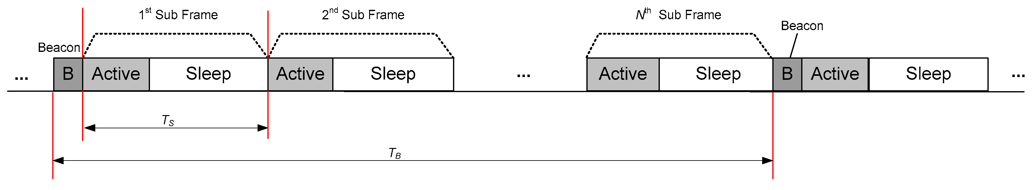
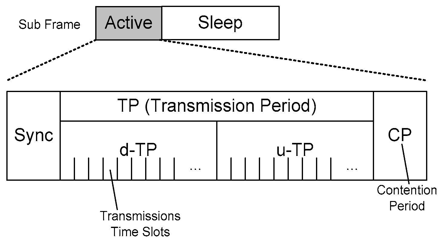
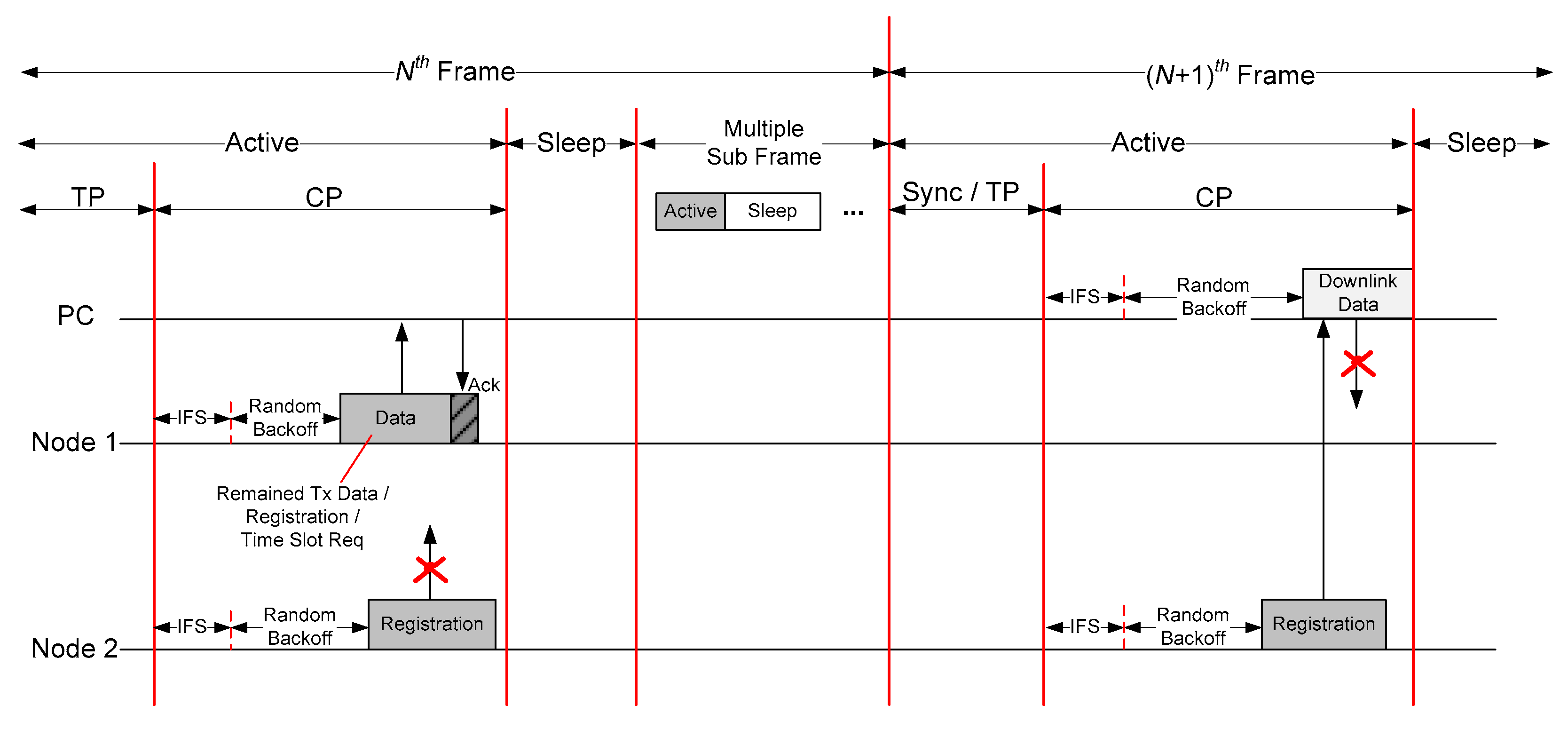
Figure 1 illustrates the overall structure of the MAC protocol which we proposed in this paper. The superframe is composed of a Beacon frame and multiple subframes, and each subframe is combined with an Active frame and a Sleep frame. Furthermore, each Active frame at every subframe is composed of several periods; Sync, Transmission Period (TP), and Contention Period (CP) as shown in 
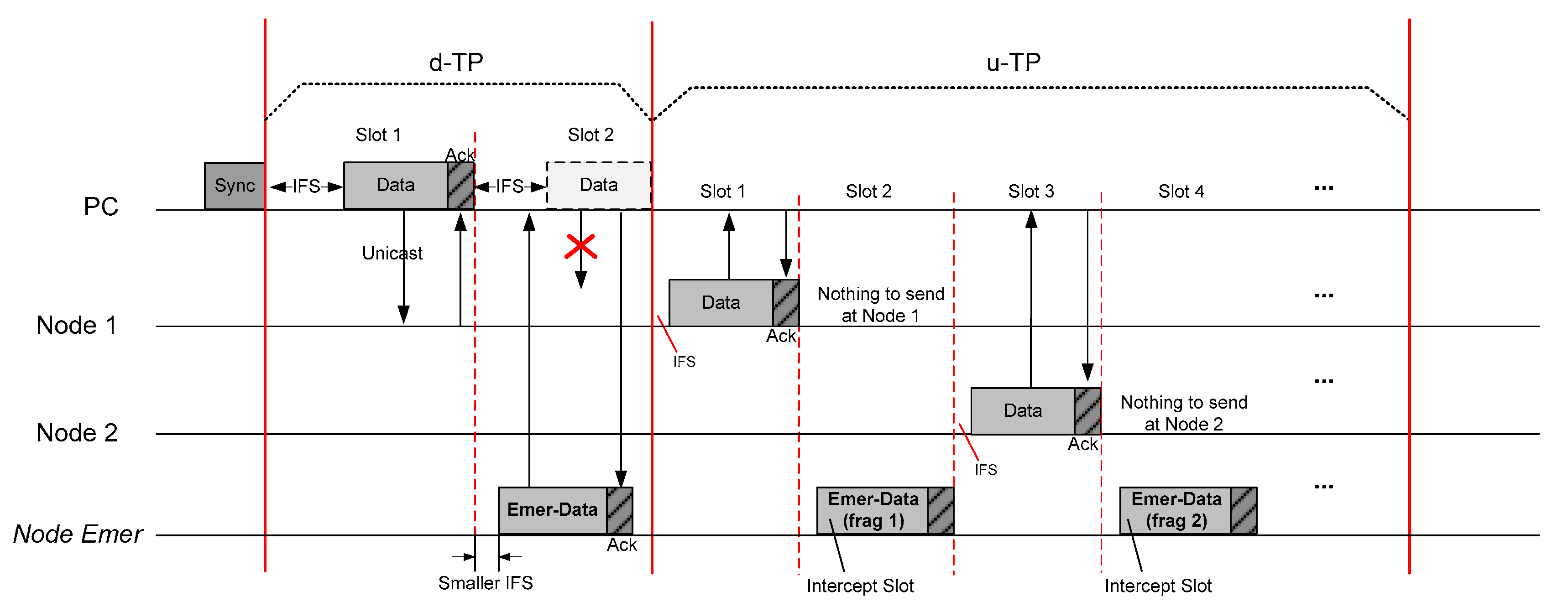
Figure 2. TP in the Active frame is composed of both d-TP and u-TP; d-TP denoted for downlink directional transmission period from a PC to an individual node, and u-TP denoted for uplink transmission.
The beacon packet is generated from PC and it is disseminated to all nodes in Beacon frame with relatively long term interval denoted as TB. As discussed in the previous paragraph, one beacon frame is followed by multiple frames in each TB as shown in Figure 1. Moreover, TS, which denotes the time duration of each subframe, has relatively short term value compared with TB. Each subframe is composed of an Active frame and a Sleep frame in which the RF transceiver should keep the wake-up condition and the sleep condition. Hence, 
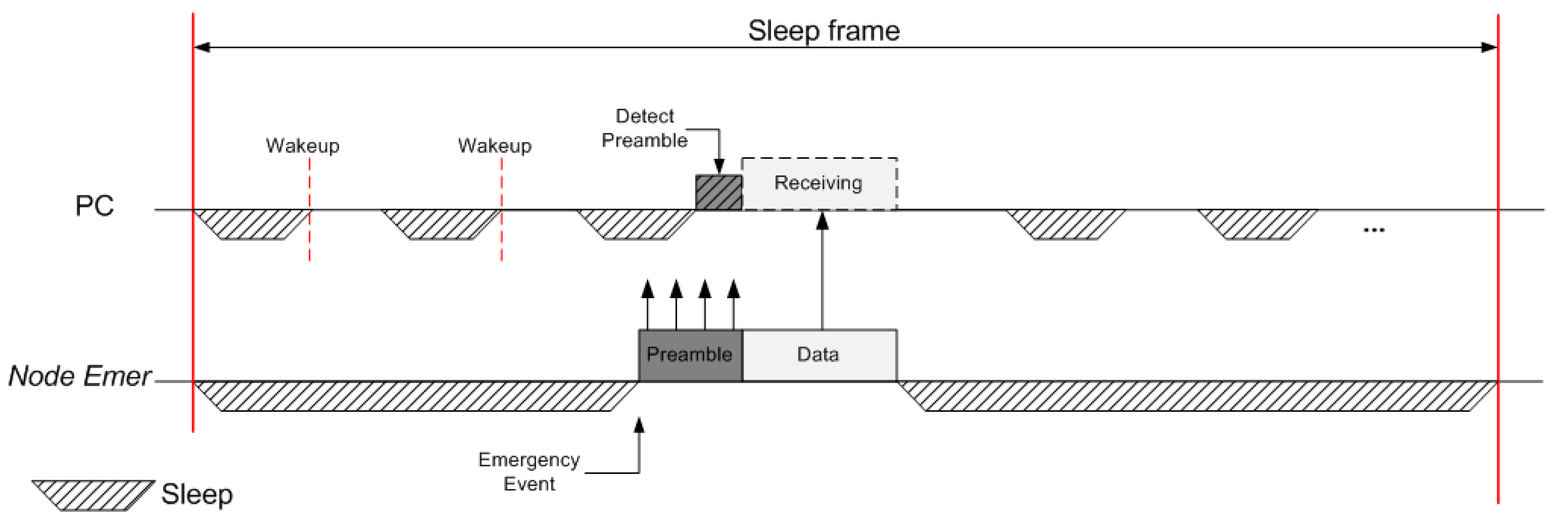
TB could be considered as the duty cycle of the transceiver. Moreover, in Sleep frame, the PC and all nodes enter to the condition of deep sleep or standby status for energy conservation. Hence, all transmissions are basically absent during Sleep frame, but we allowed for an exception in the case of emergency data transmission.
To synchronize every frame between the coordinator and each correspondent node, the PC should periodically transmit the beacon packet containing both TB and TS. Every node belonging to the same coordinator can be aware of the start time to be awake depending on TB and reception time of the packet, and each node can also estimate the reception time of the next beacon packet from the same PC. Consequently, if a node does not have any packet to send, it can omit all forwarding frames and can just sleep until the next Beacon frame.
On the other hand, Sync period is for disseminating Sync packet to awaken nodes from PC, which contains each time offset values for d-TP, u-TP, CP, and Sleep frame. The Sync packet is always sent from a PC at every TB, and we design that each subframe can be alternatively applied to each node. Each corresponding node should decide to participate in the current subframe or not. The rest of a subframe is CP, and we adapt the exceptional case of allowing contentions based on CSMA/CA from nodes on this period, in which this period supports the registration of a new node joining in.
Under the given timeframes above, all transmissions except in CP should be critically controlled by the PC. By the way, emergency data transmission must be transmitted without any authentication by PC. IEEE 802.15.6 protocol allows the emergency data transmission by out of coordinator, but it allowed in only EAP and RAP. However, emergency data related to the biomedical signal must be immediately sent regardless of the timeframe condition. For this reason, we also designed a mechanism to minimize the latency of emergency data transmission. In the proposed scheme, the emergency data transmission can be allowed in overall time frames (i.e., d-TP, u-TP, CP. And even Sleep frame) with prioritized channel preemption.
As we described previously, the PC relatively has sufficient energy resource than nodes so that the main goal of the proposed MAC protocol is designing an asymmetrical energy balance model between PC and nodes. Meanwhile, it is fundamentally required that the energy consumption point should be loaded into a PC as possible for conserving the energy of nodes side. The nodes should wake up on the only essentially required moment.

3.2. Transmit Period (TP)

TP is assigned for transmission duration between PC and nodes. Under the characteristics of WBAN, we focused on transmission topology as Piconet cluster which is used in Bluetooth technology. The direct transmission between nodes is not allowed, but can be forwarded via PC. Hence, we considered two-way transmissions of downlink and uplink in TP.
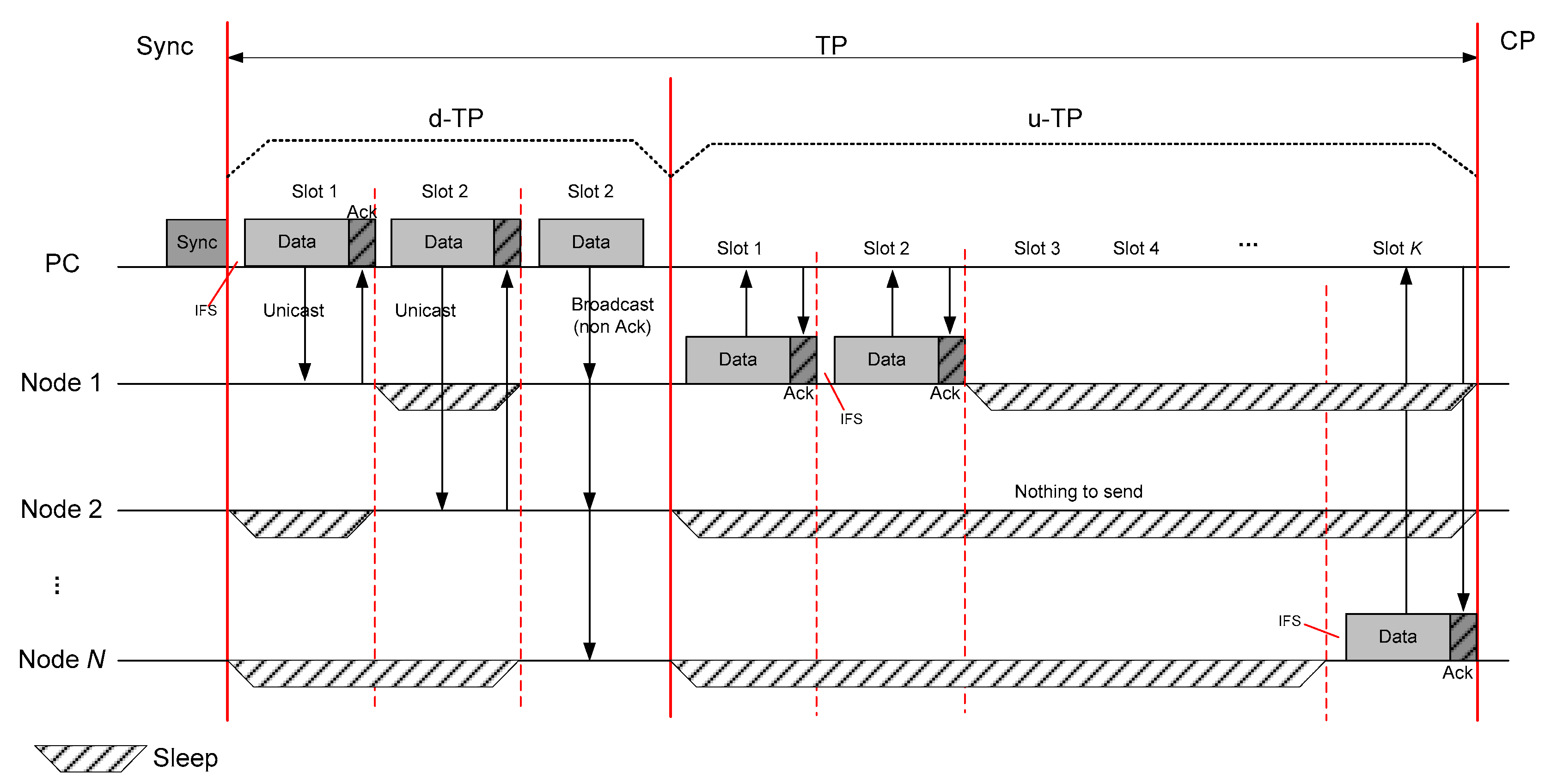
d-TP allows data to be sent from PC; both unicast and broadcast methods. Regardless of unicast or broadcast, the PC can transmit data anywhere, but the nodes cannot be aware of when the PC can send to them. Hence, we divide the d-TP by multiple time slots, and considered both unicast and broadcast. The Sync packet contains time offsets, destination address, and type (unicast or broadcast), depending on each d-TP slot.
After a node receives the Sync packet from the PC, it finds all d-TP slots assigned to broadcast type, and also finds the destination addresses matched to itself if the type is unicast. Based on the Sync packet, each node can be aware of when it has to be awake to receive data from PC and when it can sleep. If a node is selected as a receiver but cannot detect any preamble after Inter Frame Space (IFS), it should process an Early-sleep mechanism [11]. Note that IFS is existed for guaranteeing the turnaround time of transceiver transaction and for supporting the prioritized emergency data transmission.
For the next step, u-TP is also divided into multiple time slots as shown in Figure 2, and all slots are fairly assigned for all nodes. In this period, all nodes do not have to keep a wake-up state. The node only wakes up if it has data to send to the PC. After a node finds the schedule of d-TP from the Sync packet reception, it accesses the assigned d-TP slots and transmits data. If a node cannot complete the transmission during the assigned time slots, it can continue to transmit the remaining data during CP using the competition approach. Moreover, the PC always wakes up during overall u-TP for successful reception.
In both d-TP and u-TP, the Ack mechanism should be performed within the same time slot of the corresponding data transmission as shown in Figure 3. Specifically, one-time slot covers one data packet and one Ack packet. That is, the overall TP can be considered as a contentionless period because any packet does not collide in this period.
The downlink transmission occurs only when the PC will configure or change some parameters of time schedule. u-TP is helpfully used to report periodic medical signals, such as vital sign, ECG, and EEG, meanwhile d-TP is not frequently required. For these characteristics, we employed selective d-TP assignment to allow the Sync packet to include the information of d-TP schedule only when it is required.

3.3. Contention Period

CP is assigned for transmission of remaining data to be sent to the PC from the node and for transmission of specific control packets such as new node registration or slot request for u-TP. In this period, as shown in Figure 4, all nodes and PC are performing transmission including emergency data with CSMA/CA mechanism after IFS duration since the start time of CP.
All transmissions in CP can be classified into the remaining data, emergency data, and specific control frames such as registration and u-TP slot request. If a node or some nodes did not complete data transmission during the assigned u-TP, they can additionally continue to transmit it in this period with competition based on CSMA/CA, so this period can be alternatively used with TP. Furthermore, if a node tries to register at the given network or changes its slot, it can also try to request to the PC via this period.
As the mechanism of TP, CP also employs Ack so all types of packet should be followed by Ack. After PC receives a request for registration or slot change, it should apply and broadcast the changed schedule after the next subframe through the Sync packet. On the contrary, PC can deny the request from nodes by notifying Nack to the corresponding node if there is any reason to reject the request (e.g., overheated congestion or overflowed capacity). In this case, the node neglected by PC can try to again at the next Beacon time. Note that all transmissions should be competitively sent based on CSMA/CA regardless of any direction (downlink or uplink), and also note that PC should also participate in the competitive transmission with the nodes in CP.
Basically, CP would be required in a few cases. Hence, it is very low frequency to be incurred. To address this situation, it is recommended to allocate CP whenever multiple frames are passed. As a result, all nodes can participate in the competition of CP when it is detected via Sync packet. If a new node failed to be registered, it should keep going on sleep state before the next CP which can be found by each Sync packet.

3.4. Sleep Frame

Presently, many low-powered MAC protocols have employed the Duty Cycle mechanism to overcome the energy constraints so this paper also employed it. As described in Basic Framework subsection, every subframe is composed of an Active frame and Sleep frame. There is no transmission in Sleep frame except emergency data transmission, so all nodes maintain the sleep state during Overall Sleep frame. However, the PC has to perform the Duty Cycle mechanism by periodically switching both wake-up and sleep status because the proposed MAC protocol adapts emergency data transmission with conservation of energy efficiency at most periods.

4. Emergency Data Handling

In the Healthcare system, it is fundamentally required to provide minimized latency for immediate transmission of emergency data when the human body is suffering from severe emergency situation. However, many types of research have just focused on separated time slot assignment for emergency data transmission, and they could not fulfill the optimized solution due to holding contention-free approach. Hence, we have focused on finding the appropriate solution to guarantee prioritized QoS of emergency data transmission. In the proposed MAC protocol, the emergency data can be sent at any time.

4.1. IFS for Active Slot Period

Figure 5 shows the sample case where a node transmits its emergency data during d-TP and u-TP. As previous section including Figure 3 and Figure 4, all data have to be delayed for a short IFS time before transmission according to the overall timeframe (d-TP, u-TP, and CP), except the Sync period. Thus, it clearly provided QoS because the emergency data could be sent by preempting the time moment of IFS in overall TP and CP, prior to other transmissions.
In the left side of Figure 5, the emergency data transmission of Node_Emer can be earlier started with short IFS (SIFS) than PC during IFS in d-TP, so the emergency data can be prioritized to be transmitted even though the time slot was not assigned to Node_Emer. In this case, the PC should perform CSMA/CA to guarantee the reliability and QoS of the emergency transmission if it is existed. This process could be identically operated in CP. Although the nodes should consume energy due to carrier sense in CP, this period is seldom allocated in terms of overall superframe.
Meanwhile, the right side of Figure 5 shows how the emergency data could be transmitted within u-TP. Contrary to the case of d-TP, general data transmission in u-TP is relatively significant because this period is the main stem in the healthcare system. Hence, the proposed MAC protocol allowed for the emergency data to be sent only when the idle slot is detected, for conserving energy of the nodes from carrier sense. We believe that the average delay of emergency data transmissions is not critical because not all nodes are using all assigned slots.
Even though TP (including d-TP and u-TP) and CP are existed for normal data and special control packet transmissions, the emergency data can be concurrently transmitted with high priority with maintaining normal data transmission function. The only weak point is that a node consecutively transmits massive emergency data. However, this situation could be easily addressed by conducting fragmentation if the required time is greater than a time slot, as shown in the right side of Figure 5. Furthermore, we considered that PC should accept an emergency data from a node even though it was not registered to PC before.

4.2. Energy-Detection Method for Emergency Transmission on Sleep Frame

As described in previous section, while the nodes sleep in Sleep frame, the PC performs Duty Cycle during the same time for receiving the emergency data transmissions from any node, regardless of whether it is registered or not. During the Sleep frame, we employed LPL (Low Power Listening) mechanism on PC derived from B-MAC [12]. In this frame, while the nodes must not transmit any general data, the PC has to perform Duty Cycle to detect the preamble signal of the emergency transmission in Sleep Frame and will keep the wake-up state if any preamble is detected because every node can transmit emergency data at any time in this frame.
If a node tries to transmit emergency data in this frame, it configures larger preamble length than the sleep period of the Duty Cycle as shown in Figure 6, to prevent the PC from missing the emergency data due to Duty Cycle. In this situation, Ack is not required because the PC has been absolutely awake since it has detected preamble signal from the node. The nodes are allowed to send data only in case of emergency condition during this frame. Consequently, the PC can successfully receive the emergency data transmissions as well as maintain the energy efficiency.
As a result, since the length of Sleep frame is initially configured, PC performs duty cycle based on LPL mechanism, and nodes just constantly sleep in this period if they don’t have emergency data transmission. If a node has emergency data to be transmitted, it just sends data with a long preamble signal.

5. Performance Evaluation

To achieve an appropriate evaluation for the proposed MAC protocol, we have evaluated it with two approaches both numerical analysis and experiments. The aSymMAC has not only shown a reasonable superframe structure to allow periodically reporting normal data measured by on-body nodes such as Vital Sign and ECG, but also outperforming the method that can concurrently achieve minimized delivery delay for emergency data transmissions during normal data handling, as described in previous section. From here on, we would describe and prove the performance of our proposed scheme in terms of transmission delay and energy efficiency, for both normal and emergency data transmissions.

5.1. Analytic Definitions and Experimental Environment

Table 1 shows symbol definitions for further convenience in explaining the numerical analysis, which would be illustrated in the next section. For clarification, we assume that all data have same size for protocol utilization.
Meanwhile, we have performed experiments with the simulation environment presented in Table 2. For simulating a real environment, we consider many variables of data length with MTU (Maximum Transmission Unit) and power consumption in each state (Tx, Rx, Sleep), referring data sheets of CCxx families from TI Inc. [13], which are popularly used for low power communications. IEEE 802.15.6 standard technology was employed for the comparison results.

5.2. Latency Analysis of Emergency Transmission

Meanwhile, the transmission latency of normal data does not need minimized delay, emergency data must be delivered to PC as immediate as possible. For the evaluations, we analyzed the numerical results of the transmission delay from both normal data and emergency data transmissions.
The overall time duration at the viewpoint of the whole superframe expressed as Dsuper could be presented as Equation (1).
D s u p e r = ( D a c t i v e + D s l e e p ) η + D b e a c o n = ( D s y n c + D d T P + D u T P + D C P + D s l e e p ) k + D b e a c o n
defined by the following equation. The opportunity of nodes to send normal data should exist in u-TP and CP. Hence, the equation employed L variable in these periods, compared with the constant time duration denoted as D.
L t o t a l n = 1 2 ( L u T P n + L C P n + D s y n c + D d T P + D s l e e p + D b e a c o n η )
Moreover, at the viewpoint of the respective time period, the latency of Lu-TP at a given node denoted as m could be described as Equation (3), considering that the probability of opportunity to transmit at kth time slot might be k/n.
L u T P ( m ) n = k u n ( T I F S + T D a t a + T A c k )
Hence, the average latency of each node during both u-TP and CP denoted as respective Lu-TP and LCP could be presented as follows, where the deviation of time drift of nodes and PC are denoted as εn and εc, respectively. In Equation (5), we needed to consider the occurrence ratio of each control frame in CP, such as slot request or registration request denoted as λslot and λreg variables, respectively.
L u T P n = k u n 2 δ n ( T I F S + T D a t a + T A c k ) 2 ( ε n + ε c ) δ = n 1 k u ( n + 1 ) ( T I F S + T D a t a + T A c k ) ( ε n + ε c )
L C P n = O a v r + ( 1 ( γ + λ r e g + λ s l o t ) 1 ) ( T D a t a + T A c k ) = T I F S + 1 2 ( O M A X + O min ) + ( 1 ( γ + λ r e g + λ s l o t ) 1 ) ( T D a t a + T A c k )
Meanwhile, the emergency data could be transmitted in d-TP, u-TP, CP, and Sleep frame if each condition is satisfied, so the expected latency of the emergency data transmission should be differently described as below Equation (6) by Equation (1).
L t o t a l e = 1 2 ( L d T P e + L u T P e + D s y n c + L C P e + L s l e e p e + D b e a c o n η )
Contrary to normal data transmission, emergency data can be sent at any time if allowed. Since it has smaller IFS denoted as TSIFS than the other case(TIFS) to preempt the opportunity to transmit with high priority in d-TP and CP, the emergency data should be accepted to transmit only when the condition of the given time slot is idle in u-TP. Hence, in each time slot, we have considered the number of nodes and have seen the probability of whether other normal data transmission is incurred or not, denoted as ρ. By these cases, the expected value of each period could be presented as follows.
L d T P e = T S I F S + T D a t a + T A c k
L u T P e = ( ρ 1 + ρ 2 + ρ 3 ρ k u ) ( T I F S + T D a t a + T A c k ) = δ k u { 1 ( 1 λ u ) n } δ 1 ( 1 λ u ) ( T I F S + T D a t a + T A c k ) = [ 1 { 1 ( 1 λ u ) n } k u ] ( T I F S + T D a t a + T A c k )
As mentioned in Section 4.2, the PC just performs the duty cycle mechanism in Sleep frame, and the node which has emergency data has to transmit a fixed long preamble that should be larger than the interval of the duty cycle that the PC performs. In the nodes, the latency in CP has the same value in d-TP because the nodes get always prioritized transmission opportunity in d-TP, compared with PC. Therefore, the latency of emergency data transmission in Sleep frame could be the following Equation (9) and the latency of that in CP also could be Equation (10).
L s l e e p e = φ + T D a t a
L C P e = L d T P e
With the above equations from Equations (1)–(10), we performed an experiment with the environmental parameters shown in Table 2. We found that the latency of emergency data transmission showed outstanding results compared with the normal data transmission. In this experiment, we employed one coordinator and variable nodes. Figure 7 and Figure 8 show the comparison results according to the number of nodes and traffic amount in each transmission rate.
Figure 7 shows the results of average latency according to the number of nodes where they have same traffic. In this case, we fixed the traffic amount from all nodes as 1 packet/s per node and increased the number of the node to verify the latency of normal data transmission. Figure 8 shows the average latency from all nodes according to the variable traffic. Even though the latency of normal data transmission could not show the enhanced latency compared with IEEE 802.15.6, it could not say that the proposed MAC has more weakness because the amount of differentiation is too small and this could be changed by adjusting the parameters related to time schedule. Moreover, we could find that aSymMAC showed better performance than IEEE 802.15.6 beyond 0.4 of traffic interval in Figure 8. Therefore, the proposed scheme would show enhanced latency at high traffic environment.
To consider the different speed on the PHY layer, we simulate 128 kbps and 32 kbps of transmission rates and present the results in Figure 7 and Figure 8. Both results similarly show the pattern of differentiation of delivery time on IEEE 802.15.6 and normal transmission on the proposed scheme; higher transmission rate induces lower delivery time. However, it cannot easily say that the differentiation of two transmission rates is high, because both mechanisms are depending on slot assignment structure. Meanwhile, in high traffic environment, high transmission rate can mitigate congested competition during contention period (RAP in IEEE 802.15.6 and CP in aSymMAC). Moreover, this condition can provide more opportunities to transmit normal data during contention-less period (Type I/II in IEEE 802.15.6 and u-TP in aSymMAC). Hence, Figure 8 shows the higher differentiation results of both protocols in high traffic environment.
Contrary to Figure 7 and Figure 8, the latency of the emergency data transmissions show different results as illustrated in Figure 9. In this experiment, we constantly fixed the number of nodes as 4 and also fixed the normal data transmission amount on each node as shown in Table 2. Then, we set another node to transmit only emergency data with varied traffic amount. We finally measured outperforming results comparing with any other scheme as shown in Figure 9.
The differentiation of each transmission rate in the results of IEEE 802.15.6 protocol can be explained with the same reason described in Figure 8 and Figure 9. However, we have to focus on the emergency data transmission on aSymMAC. In this protocol, every emergency data can obtain high opportunity to be transmitted by prioritized IFS (i.e., SIFS), preliminarily to normal data that has relatively longer IFS. Consequently, Figure 9 shows narrow differentiation results of this case.
Figure 10 and Figure 11 show the saturated throughput with various payload length and the amount of external interference. The saturated throughput presents the relative value of bandwidth efficiency where the maximized value (i.e., 1.0) implies that the given channel is being constantly used for data transmission at every time. Hence, the value of 1.0 is ideal and unrealistic because some overheads are essentially required (e.g., packet header, Ack, IFS, Back-off, etc.) to be operated by MAC protocol.
In the results of IEEE 802.15.6 and normal data transmission of aSymMAC in Figure 10, both protocols similarly present that less payload length makes lower bandwidth efficiency due to the heavy overhead; header and Ack mechanism are commonly applied even if data payload is too small. On the other side, we can see that the excessive payload length makes worse performance caused by that too larger payload length overflows assigned time slot and aggravates competition on contention period. Moreover, this can make more collisions. Meanwhile, the case of emergency transmission on aSymMAC shows better performance because every emergency transmission can preliminarily preempt the channel regardless of slot assignment.
In addition, we evaluate the robustness of these protocols by giving external interference on the same frequency. We employed IEEE 802.15.4 as an interference method with the change of frequency and channel space. Note that the value of 100% implies that IEEE 802.15.4 fully occupies the given channel in time domain. All results at 100% of the interference are not equal to zero because IEEE 802.15.4 also performs CSMA/CA during contention period. As a result, we can see the better performance from the case of emergency transmission on aSymMAC. The emergency transmission can take more opportunities due to cutting off CSMA/CA while IEEE 802.15.4 does the opposite.

5.3. Energy Efficiency of Nodes and PC

In this subsection, we described the results of energy efficiency of the proposed MAC by analyzing the energy consumption from both PC and nodes. Depending on the parameters described in Table 1, the overall energy consumption of PC denoted as EC could be illustrated as follows:
E C = E a c t i v e C + E s l e e p C + E b e a c o n C η = E s y n c C + E d T P C + E u T P C + E C P C + E s l e e p C + η 1 E b e a c o n C
The energy consumption of Sync and Beacon periods within one superframe could be simply described as below equations where P parameter would be classified into PTx, PRx, and Pidle on each radio transceiver condition (Tx, Rx, and idle listening status). Note that the duration of each period is not equal to the interval value.
E s y n c C = P T x D s y n c E b e a c o n C = P T x D b e a c o n
In TP, the data transmission from a PC can be incurred or not. Therefore, the analysis of energy consumption in u-TP and d-TP has to consider the occurrence probability of data transmission event and dependently assigned uplink and downlink time slot numbers denoted as ku and kd, as below Equations (13) and (14), respectively.
E u T P C = ( P i d l e T I F S + P R x T D a t a + P T x T A c k ) λ u k u + P i d l e ( T D a t a + T A c k ) ( 1 λ u ) k u + ( P i d l e T I F S + P R x T D a t a + P T x T A c k ) λ e k u = k u ( λ u + λ e ) × ( P i d l e ( T I F S + ( ( λ u + λ e ) 1 1 ) ( T D a t a + T A c k ) ) + P R x T D a t a + P T x T A c k )
E d T P C = k d ( P i d l e ( T I F S + ( 1 λ d ) ( T D a t a + T A c k ) ) + P T x ( λ d T D a t a + λ e T A c k ) + P R x ( λ d T A c k + λ e T D a t a ) )
In addition, the overall energy consumption of the PC in CP could be illustrated as below equation where both the energy consumptions for emergency data and normal data transmission were denoted as EEmergency and ENormal, respectively.
E C P C = λ e E E m e r g e n c y + ( 1 λ e ) ( λ r e g + λ s l o t + λ r e m a i n ) E N o r m a l
For more simplification of the analysis, we solve the above equation where the length values of all packets including the slot request, registration request, and request for remaining data transmission have the same size.
E C P C = λ e ( P R x T D a t a + P T x T A c k ) + ( 1 λ e ) ( ( λ r e g + λ s l o t + λ r e m a i n ) ( P R x T D a t a P i d l e ( T D a t a + T A c k ) ) + λ r e m a i n P T x T A c k + P i d l e ( T D a t a + T A c k ) )
In sleep period, a PC should perform LPL mechanism for allowing data reception of emergency data from any node. Hence, we could describe the energy consumption of a PC with the values of duty cycle interval, wake-up duration, and long preamble length depending on LPL respectively denoted as Tduty, Twakeup, and ωp, as below equation.
E S l e e p C = P R x λ e ( ω p 2 R + T D a t a ) + ( 1 λ e ) P i d l e D S l e e p T w a k e u p T d u t y
Meanwhile, the average energy consumption value of nodes could be also described as below.
E N = E s y n c N + E d T P N + E u T P N + E C P N + E s l e e p N + η 1 E b e a c o n N
The energy consumption of a node could be induced by the same approach from Equation (12) with just cross match between the transmitter and receiver, as below equation.
E s y n c N = P R x D s y n c E b e a c o n N = P R x D b e a c o n
In this case, a node may receive only one packet or nothing from a PC in d-TP, so the energy consumption of a PC in this period could be presented as below.
E d T P N = λ d ( P T x T A C K + P R x T D a t a ) + P i d l e ( λ d T I F S + ( λ d + k d 2 λ d k d ) ( T D a t a + T A C K ) )
In u-TP, all nodes possibly have variable transmission event to the corresponding PC. The probability of an uplink event from a node can be affected by the cumulated transmissions that were not sent during the last u-TP and the last CP. Additionally, the number of uplink transmissions from a node could be limited by the number of assigned time slot. For simplification, the analysis of the energy consumption could be calculated under the assumptions that all slots are fairly distributed to all nodes but that all nodes have different number of uplink transmissions, as below equation. Note that the maximum slot number per a node could be presented as [Ku/N] with the Gauss function, with the number of data presented as π.
E u T P N = l = 0 [ K u N ] P ( π = l ) { E D a t a + ( [ K u N ] l ) E i d l e } E D a t a = P i d l e T I F S + P T x T D a t a + P R x T A C K E i d l e = P i d l e ( T I F S + T D a t a + T A C K )
In CP, all nodes should perform pseudo random back-off delay after IFS whenever any data would be transmitted, but this would not affect the given time duration. Hence, we do not have to consider the random seed value for back-off delay when calculating the energy consumption described below.
E C P N = λ e { P T x T D a t a + P R x T A C K + P i d l e ( D C P λ e ( T D a t a + T A C K ) ) }
A node generally keeps deep sleep mode in overall SP. However, when any emergency data is incurred, a node has to attach long preamble prior to the emergency data for successful reception from the PC which operates LPL mechanism in SP. Therefore, the energy consumption of a node in Sleep frame could be presented below.
E S l e e p N = λ e { P T x ( φ + T D a t a ) + P i d l e ( D s l e e p φ T D a t a ) }                 + ( 1 λ e ) P i d l e D s l e e p = λ e ( P T x P i d l e ) ( φ + T D a t a ) + P i d l e D s l e e p
Furthermore, we achieved simulation-based experiments to obtain realistic results compared with IEEE 802.15.6 protocol as shown in Figure 12 and Figure 13 under the same scenario described in the previous subsection and Table 2. In this experiment, we operated a given network composed of one coordinator and several nodes during 100,000 s, and then we individually measured the total energy consumption of them.
Figure 12 and Figure 13 show the cumulated energy consumption of the coordinator and the node employed in this simulation, according to the variable number of nodes and variable traffic amount. They also show the results of IEEE 802.15.6 protocol with the same conditions. In these figures, the proposed aSymMAC could not show the enhanced performance in PC compared with IEEE 802.15.6 protocol. However, it is not conclusively important in the real environment because a PC generally has the function of energy recharging and also has more powerful energy resource than the micro-sized on-body nodes.
Meanwhile, these figures present outstanding energy efficiency of the node side on the aSymMAC protocol compared with IEEE 802.15.6, and this is the key contribution of this research. In real environment, WBAN needs the extreme energy efficiency of the node side, but not PC. Figure 12 and Figure 13 consequently prove that aSymMAC gives higher energy efficiency of the node than IEEE 802.15.6 and that the differentiation of energy efficiency between the coordinator and each node is not narrower on aSymMAC than IEEE 802.15.6. As a result, we can recognize that the main goal of this research has been accomplished.
From understanding these results from the overall figures in this section, we could find that the proposed MAC could achieve the enhancement of previous mechanisms even though some points might not be improved (e.g., the latency of normal data transmission and the energy efficiency of PC). However, in this case, the latency of normal data transmission and the energy efficiency of PC are not critically significant in the real environment.

6. Conclusions

Considering real environment of WBAN, the on-body node may have very constraint energy resource compared with the coordinator. In addition, emergency data incurred from a dangerous condition of the human body has to be preferentially delivered and reported to the coordinator or corresponding backend systems. These two elements have to be fundamentally required to meet the WBAN environment. We proposed a new scheme called aSymMAC protocol to satisfy the above two essential requirements. Moreover, the proposed scheme was evaluated with an analytic method and experiments focusing on the above two issues, and was compared with IEEE 802.15.6 which is the representative standard technology for WBAN environment. However, TDMA-based MAC protocols are vulnerable from the interference problem and aSymMAC could not be completely avoided from this problem. In advance, when many people who exploit aSymMAC-based healthcare system were spatially congregated, a solution to reassemble frame structure should be strongly required to address homogeneous interference from other WBAN. We will focus on this issue for further research.

Acknowledgments

This work was supported by the National Research Foundation of Korea (NRF) grant funded by the Korea government (MSIP) (No. 2016R1C1B1015863) and the Ministry of Education of the Republic of Korea and the National Research Foundation of Korea (NRF-2017R1D1A3B04034151).

Author Contributions

Jaeho Lee contributed by deriving the initial numerical and experimental results and by making the draft version of the paper. Seungku Kim was responsible for the main idea, theoretical analysis, coordination, and proofreading.

Conflicts of Interest

The authors declare no conflict of interest.

References

  1. Patel, M.; Wang, J. Applications, Challenges, and Prospective in Emerging Body Area Networking Technologies. IEEE Wirel. Commun. 2010, 17, 80–88. [Google Scholar] [CrossRef]
  2. IEEE 802.15.6: Wireless Body Area Networks. IEEE Standard for Local and Metropolitan Area Networks. 2012. Available online: http://ieeexplore.ieee.org/document/6161600 (accessed on 14 November 2017).
  3. IEEE 802.15.4: Wireless Medium Access Control (MAC) and Physical Layer (PHY) Specifications for Low-Rate Wireless Personal Area Networks (WPANs). IEEE Standard Information Technology. 2006. Available online: http://ieeexplore.ieee.org/document/4299496 (accessed on 14 November 2017).
  4. Li, H.; Tan, J. Heartbeat Driven Medium Access Control for Body Sensor Networks. HealthNet 2007, 14, 25–30. [Google Scholar]
  5. Moulik, S.; Misra, S.; Chakraborty, C.; Obaidat, M.S. Prioritized payload tuning mechanism for wireless body area network-based healthcare systems. In Proceedings of the Global Commun (GLOBECOM), Austin, TX, USA, 8–12 December 2014; pp. 2393–2398. [Google Scholar]
  6. Zhou, J.; Guo, A.; T Nguyen, H.; Su, S. Intelligent Management of Multiple Access Schemes in Wireless Body Area Network. J. Netw. 2015, 10, 108–116. [Google Scholar] [CrossRef]
  7. LI, C.; LI, H.B.; Kohno, R. Reservation-Based Dynamic TDMA Protocol for Medical Body Area Networks. IEICE Trans. Commun. 2009, 92, 387–395. [Google Scholar] [CrossRef]
  8. Fang, G.; Dutkiewicz, E. BodyMAC: Energy efficient TDMA-based MAC protocol for wireless, body area networks. In Proceedings of the 9th IEEE International Symposium on Communications and Information Technology ISCIT, Icheon, Korea, 28–30 September 2009; pp. 1455–1459. [Google Scholar]
  9. Khan, Z.A.; Sivakumar, S.; Phillips, W.; Aslam, N. A new patient monitoring framework and Energy-aware Peering Routing Protocol (EPR) for Body Area Network communication. J. Ambient. Intell. Hum. Comput. 2014, 5, 409–423. [Google Scholar] [CrossRef]
  10. Lee, J.; Kim, J.; Eom, D. A delay-tolerant virtual tunnel scheme for asynchronous MAC protocols in WSN. Wirel. Pers. Commun. 2013, 70, 657–675. [Google Scholar] [CrossRef]
  11. Buettner, M.; Yee, G.V.; Anderson, E.; Han, R. X-MAC: A Short Preamble MAC Protocol for Duty-Cycled Wireless Sensor Networks. In Proceedings of the 4th ACM International Conference on Embedded Networked Sensor Systems, Boulder, CO, USA, 31 October–3 November 2006; pp. 307–320. [Google Scholar]
  12. Polastre, J.; Hill, J.; Culler, D. Versatile Low Power Media Access for Wireless Sensor Networks. In Proceedings of the 2nd ACM International Conference on Embedded Networked Sensor Systems, Baltimore, MD, USA, 3–5 November 2004; pp. 95–107. [Google Scholar]
  13. TI CC1100 Datasheet. Available online: http://www.ti.com (accessed on 14 November 2017).
Figure 1. Overall frame structure of the proposed aSymMAC protocol.
Applsci 08 00092 g001
Figure 2. The 3-period types (Sync, Transmission, and Contention Period) in the Active subframe.
Applsci 08 00092 g002
Figure 3. Transmission example of TP (Transmission Period) which composed of d-TP (downlink-TP) and u-TP (uplink-TP) in the Active subframe.
Applsci 08 00092 g003
Figure 4. Transmission example of CP (Contention Period) in the Active subframe.
Applsci 08 00092 g004
Figure 5. Emergency transmission with prioritized IFS in d-TP and with idle slot preemption in u-TP.
Applsci 08 00092 g005
Figure 6. Duty cycle mechanism for emergency data reception in Sleep subframe from Coordinator.
Applsci 08 00092 g006
Figure 7. Average delivery time of normal and emergency data transmissions according to the increment of the number of nodes compared with the IEEE 802.15.6 protocol.
Applsci 08 00092 g007
Figure 8. Average delivery time of normal data transmissions according to the traffic amount compared with the IEEE 802.15.6 protocol.
Applsci 08 00092 g008
Figure 9. Average delivery time of emergency data transmissions according to the traffic amount with fixed normal data transmissions compared with IEEE 802.15.6 protocol.
Applsci 08 00092 g009
Figure 10. Average saturated throughput depending on bandwidth efficiency according to the payload length per a packet compared with IEEE 802.15.6 protocol.
Applsci 08 00092 g010
Figure 11. Average saturated throughput depending on bandwidth efficiency according to the external interference on the same frequency compared with IEEE 802.15.6 protocol.
Applsci 08 00092 g011
Figure 12. Cumulated energy consumption amount of both coordinator and node according to the increment of the number of nodes compared with IEEE 802.15.6 protocol.
Applsci 08 00092 g012
Figure 13. Cumulated energy consumption amount of both coordinator and node according to the traffic amount compared with IEEE 802.15.6 protocol.
Applsci 08 00092 g013
Table 1. Symbol descriptions for analyses.
SymbolDescriptionSymbolDescription
NNumber of NodesEC, ENEnergy Consumption of respective PC and Node
kNumber of Time SlotsTIFS, TDataTime delay for IFS and data transmission
ηNumber of Active FramesRData Rate
ΓNumber of Remained DataLn, LeAverage Latency of respective normal and emergency data transmissions
πNumber of Data Tx Event on a Node during u-TPPPower (Watt) value
εn, εcClock Drift at Nodes and PCDDuration of Time Frame
ωPacket Length of Constant DataΦDuration of Long Preamble Transmission for LPL during Sleep Period
λOccurrence Rate of Normal Data TransmissionODelay of Pseudo-random back-off
Table 2. Simulation parameters.
LayerParametersValue
PHYData Rate64/256 kbps
Tx Power2.428 (0 dBm) mW
Rx Power1.814 mW
Sleep Power0.027 mW
MACNumber of PC1
Number of nodes1 to 5
TopologyStar
Traffic Pattern128 byte/Given Interval
Communication Range5 to 10 m
Beacon Interval1 s
Period of a Sub-Frame20 ms
Active/Sleep ratio1:4 (200 ms:800 ms)
Duration of u-TP120 ms
Duration of d-TP40 ms if only required
Duration of CP40 ms
Number of time slots in u-TP6
Number of time slots in d-TP2
Number of Active frames10
Duty cycle interval of PC1 ms
Length of long preamble950 μs
Clock drift for PC and nodes40 ppm
Occurrence of control frame in CPless than 1%
Length of IFS150 μs
Length of SIFS50 μs

