Article

Effects of Order of Expansion for the Exponential Matrix and Number of Mathematical Layers in the Exact 3D Static Analysis of Functionally Graded Plates and Shells

by
Salvatore Brischetto
* and
Roberto Torre
Department of Mechanical and Aerospace Engineering, Politecnico di Torino, corso Duca degli Abruzzi, 24, 10129 Torino, Italy
*
Author to whom correspondence should be addressed.
Appl. Sci. 2018, 8(1), 110; https://doi.org/10.3390/app8010110
Submission received: 22 December 2017 / Revised: 10 January 2018 / Accepted: 11 January 2018 / Published: 14 January 2018

Abstract

:
This work deals with the study of the convergence ratio of the exponential matrix method used in the 3D static analysis of functionally graded structures subjected to harmonic loads. The equilibrium equations are written in mixed orthogonal curvilinear coordinates. This feature allows plates, cylinders, spherical and cylindrical shells to be studied with the same and unique formulation. After a reduction to first order differential equations, the obtained system is solved through the thickness by means of the exponential matrix method. The coefficients of these equations are not constant because the mechanical properties of the considered functionally graded materials change through the thickness. Moreover, the curvature terms introduce a further dependence of the coefficients from the thickness coordinate. The use of several mathematical layers allows for evaluating both the material properties and the curvature terms at certain points through the thickness direction. The M number of mathematical layers to be introduced is here studied in combination with the N expansion order of the exponential matrix. These values are influenced by several parameters. Therefore, different geometries, thickness ratios, lamination sequences, functionally graded material laws and half-wave numbers are considered.

1. Introduction

Functionally Graded Materials (FGMs) have changing properties across the volume [1]. This change in the properties is induced and described by a certain spatial function. FGMs may be obtained changing the porosity, the microstructure or the composition of the bulk material [2]. A first distinction may be done between the continuous-graded structures and the stepwise-graded structures. In the present paper, continuous-graded structures, using changing composition, are considered. A metallic and a ceramic phase are present and their related volume fractions continuously vary through the thickness direction. In the same way as the volume fraction, the mechanical and thermal properties also vary. FGMs with metallic and ceramic phases are commonly employed in aerospace field as structural components in high-temperature environments [3]. The main advantage given by continuous-graded materials is related to the possibility to achieve specific properties that common materials cannot guarantee. They do not introduce the common layers and related interfaces as in multilayered structures. This feature leads to the absence of stress discontinuities that are often at the base of delamination phenomena in classical multilayered structures. In view of the complexity of this problem, the static and dynamic analyses of structures embedding FGMs were conducted by several authors, which proposed two- (2D) and three-dimensional (3D) models for basic elements such as plates and shells. Both 3D and 2D models always need to be validated in order to confirm their capability in displacement, stress, strain and vibration evaluations. 3D exact solutions are the only tools capable of accurately evaluating the punctual behavior of these elements embedding FGM layers. These solution types are possible only for certain load/boundary conditions and for specific assumptions for the displacement components. A closed form of the equilibrium equations can be solved taking into account how the material properties change in the volume.
Square and rectangular plates are the most common geometries in the literature. Several authors proposed exact solutions for the static and dynamic analysis of these elements when functionally graded layers are included. The bending of functionally graded rectangular plates was studied by Kashtalyan [4] using the solution found by Plevako in [5] for the equilibrium equations of inhomogeneous isotropic materials. An exponential law for the volume fraction of both the phases was considered. Several results for displacements were presented. The power series method was used by Vel and Batra [6] to solve the equilibrium equations for simply supported functionally graded rectangular plates. Xu and Zhou [7] studied the 3D static exact solution of functionally graded plates discussing the effects of different thickness ratios on displacements and stresses. Yas and Tahouneh [8] studied the problem of free vibrations of FGM annular plates on elastic foundations considering different kinds of material property laws across the thickness. The equations of motion were solved using a semi-analytical approach based on series solution and on the differential quadrature method. Solutions for sandwich structures with one or more FGM layers were also proposed in the literature. The effects of different functionally graded material laws on the structural response of simply supported rectangular plates were studied by Zhong and Shang in [9], the electroelastic coupling was also analyzed. Hosseini-Hashemi et al. [10] investigated the free vibrations of a simply supported homogeneous rectangular plate coated by a functionally graded skin with an exponential law through the thickness for the elastic modulus and the mass density. Rectangular sandwich plates, with homogeneous skins and FGM core or with FGM skins and homogeneous core, were studied by Li et al. in [11]. The fundamental frequencies were found using the Ritz method. The solutions found for structures with curvatures are less numerous. Curved panels embedding functionally graded materials were studied by Zahedinejad et al. [12]. The free vibrations for panels, with arbitrary boundary conditions on two opposite edges and simply supported boundary conditions on the other sides, were presented. Cylindrical shells were studied by Alibeigloo et al. in [13], an analytical method was developed to study the free vibrations of simply supported cylinders. Vel [14] used the power series method to solve the 3D linear equilibrium equations written for functionally graded shells with simply supported edges. Dong [15] evaluated the effects of different boundary conditions on the dynamic response of functionally graded annular plates using the Chebyshev–Ritz method, a convergence analysis was also performed. Kashtalyan and Menshykova [16] studied the advantages that a functionally graded core may give in a sandwich panel in terms of the reduction of stress discontinuities at the interfaces. The closed-form solutions found in literature always consider the problem for particular boundary load conditions. Further interesting exact solutions in the literature are discussed in the following last part. Barretta [17] proposed exact solutions for equilateral triangle and elliptic Kirchhoff plates under torsion with no kinematic boundary conditions using the analogy with a beam under torsion. An extension of this solution to flexure was proposed in [18]. The introduction of Functionally Graded Materials in Barretta et al. [19] allowed for establishing a relationship between FGM orthotropic Saint–Venant beams and inhomogeneous isotropic Kirchhoff plates. Further details about the employed method can be found in [20,21].
Even though several solutions were already proposed in the literature, a lack of generality exists. The final goal of the present solution is to give a universal tool capable to include several geometries (plates, cylinders, spherical and cylindrical shells) embedding different material configurations (also including FGMs). This solution was already introduced by the first author for the free vibrations of FGM structures in [22] and extended to the static analysis of FGM plates and shells subjected to harmonic loads in [23]. The equilibrium equations are written in mixed orthogonal curvilinear coordinates and solved through the thickness via the exponential matrix method. This method may only be used when the coefficients of the differential equations are constant. When FGM layers are introduced, the mechanical properties vary through the thickness, and this feature makes these coefficients a function of the thickness coordinate z. Moreover, when the shell geometries are considered, a further dependence of these coefficients from z exists. This problem may be overcome via the introduction of mathematical layers, where the mechanical properties and the curvature-related terms may be punctually evaluated in their middle. The M number of mathematical layers and the N order of expansion for the exponential matrix are two parameters to be determined in order to have exact results.
In the convergence analysis of the proposed 3D shell solution, two terms are fundamental, they are the N order of expansion for the exponential matrix and the M number of mathematical layers. These two terms depend on several parameters such as: geometry, lamination scheme, material (classical ones or FGMs), FGM law, thickness ratio, performed analysis (static or free vibration analysis), applied loads and so on. For these reasons, a systematic analysis is necessary to understand the better combination of M and N values. However, this systematic analysis is possible only if it is separately performed for different cases in order to remark several important features. For these reasons, we have proposed four different works: the present new paper and further three past works [24,25,26]. In [24], the convergence study in terms of M and N was performed for the free vibration analysis of composite and sandwich plates and shells. Ref. [25] proposed the convergence study in terms of M and N for the free vibration analysis of FGM plates and shells. Ref. [26] showed the convergence study in terms of M and N for the static analysis of composite and sandwich plates and shells. Finally, the present new paper is about the convergence study in terms of M and N for the static analysis of FGM plates and shells. This detailed partition is fundamental for several reasons: the convergence for the free vibration analysis considers the results in terms of frequencies and vibration modes (typical eigenvalue and eigenvector problems). On the contrary, the convergence study for the static analysis considers the results in terms of displacements, strains and stresses (classical linear elastic static problem). Therefore, two different procedures are analysed and different result types are investigated and discussed. These result types can be affected by various parameters. The N order of expansion used for the exponential matrix method is strictly connected with the thickness ratio of the structure. The M number of mathematical layers is introduced for the calculation of the curvature terms in the shell geometries. However, M is also important in the case of FGM layers because it allows the punctual calculation of the FGM law through the thickness. This last feature shows as the investigation of FGM structures is fundamental to be analyzed in separated works. In fact, M value in FGM shells is used for two reasons, which are the curvature term definition and the FGM law calculation.

2. 3D Exact Static Analysis of FGM Structures

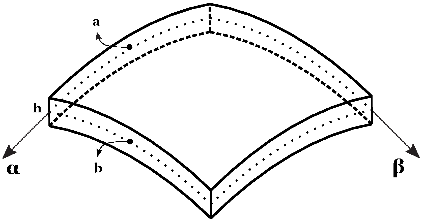
The formulation of the proposed 3D static solution has been developed in mixed orthogonal curvilinear coordinates. All the details concerning the geometry and the reference system may be found in Figure 1. A generic spherical shell is shown; the reference system ( α , β , z ) is mixed curvilinear and orthogonal. The origin is located in a corner with z being normal to the middle surface Ω 0 , heading towards the upper surface and α and β are defined on it. z varies from h / 2 to h / 2 being h the total thickness of the shell. z ˜ is a secondary thickness coordinates. It has its origin at the bottom of the shell, and thus varies from 0 to h. Figure 2 gives a clear definition of both reference coordinates. In the present paper, functionally graded materials (FGMs), which change mechanical properties only through the thickness direction z, have been taken into account. The three-dimensional linear elastic constitutive equations, written for shells embedding isotropic FGMs, must take into consideration the dependence of the elastic coefficients from the thickness coordinate z. For each k physical layer that constitutes the shell, the link between the stress vector σ k = ( σ α α k , σ β β k , σ z z k , σ β z k , σ α z k , σ α β k ) and the strain vector ϵ k = ( ϵ α α k , ϵ β β k , ϵ z z k , γ β z k , γ α z k , γ α β k ) is given by the 6 × 6 matrix C k ( z ) :
C k ( z ) = C 11 k ( z ) C 12 k ( z ) C 13 k ( z ) 0 0 0 C 12 k ( z ) C 22 k ( z ) C 23 k ( z ) 0 0 0 C 13 k ( z ) C 23 k ( z ) C 33 k ( z ) 0 0 0 0 0 0 C 44 k ( z ) 0 0 0 0 0 0 C 55 k ( z ) 0 0 0 0 0 0 C 66 k ( z ) ,
the compact form of constitutive relations is:
σ k = C k ( z ) ϵ k .
The output of the present formulation is given in terms of displacements and their derivatives made with respect to the thickness coordinate z. In order to obtain constitutive equations in displacement form, the geometrical relations must be introduced. When shells with constant radii of curvature are considered, the following parametric coefficients can be defined:
H α = ( 1 + z R α ) = ( 1 + z ˜ h / 2 R α ) , H β = ( 1 + z R β ) = ( 1 + z ˜ h / 2 R β ) , H z = 1 .
R α and R β are the radii of curvature in α and β directions, respectively. z ˜ and z are the two thickness coordinates defined above. H z = 1 because no curvature exists along the z-direction. H α and H β are the crucial points as their introduction allows for writing a general formulation valid for spherical shells with two finite radii of curvature. This formulation can be easily extended to single-curvature structures and plates. When the considered geometry is a cylinder or a cylindrical panel, R α or R β is infinite, which implies H α = 1 or H β = 1 . In the same way, when both the radii of curvature are infinite (plate geometry), H α = H β = 1 . With these parametric coefficients, the geometrical relations for each k layer of the multilayered FGM shell may be written as:
ϵ α α k = 1 H α ( z ) u k α + w k H α ( z ) R α ,
ϵ β β k = 1 H β ( z ) v k β + w k H β ( z ) R β ,
ϵ z z k = w k z ,
γ β z k = 1 H β ( z ) w k β + v k z v k H β ( z ) R β ,
γ α z k = 1 H α ( z ) w k α + u k z u k H α ( z ) R α ,
γ α β k = 1 H α ( z ) v k α + 1 H β ( z ) u k β .
These relations are written for a spherical shell with constant radii of curvature [27,28]. It is easy to see how the relations degenerate into the ones for cylinders, cylindrical shells and plates when one or both the parametric coefficients are equal to 1 ( R α or R β equals infinite). The displacement form of the constitutive equations may be obtained introducing in Equation (2) the geometrical relations of Equations (4)–(9):
σ α α k = C 11 k ( z ) H α ( z ) u , α k + C 11 k ( z ) H α ( z ) R α w k + C 12 k ( z ) H β ( z ) v , β k + C 12 k ( z ) H β ( z ) R β w k + C 13 k ( z ) w , z k ,
σ β β k = C 12 k ( z ) H α ( z ) u , α k + C 12 k ( z ) H α ( z ) R α w k + C 22 k ( z ) H β ( z ) v , β k + C 22 k ( z ) H β ( z ) R β w k + C 23 k ( z ) w , z k ,
σ z z k = C 13 k ( z ) H α ( z ) u , α k + C 13 k ( z ) H α ( z ) R α w k + C 23 k ( z ) H β ( z ) v , β k + C 23 k ( z ) H β ( z ) R β w k + C 33 k ( z ) w , z k ,
σ β z k = C 44 k ( z ) H β ( z ) w , β k + C 44 k ( z ) v , z k C 44 k ( z ) H β ( z ) R β v k ,
σ α z k = C 55 k ( z ) H α ( z ) w , α k + C 55 k ( z ) u , z k C 55 k ( z ) H α ( z ) R α u k ,
σ α β k = C 66 k ( z ) H α ( z ) v , α k + C 66 k ( z ) H β ( z ) u β k .
In Equations (10)–(15), the subscripts ,α, ,β and ,z have been introduced to compact the related partial derivative symbols α , β and z . All the coefficients that multiply the displacements and their derivatives are a function of the thickness coordinate z, even when both the radii of curvature are infinite. H α and H β depend on z when the relative curvature is concerned, the elastic coefficients depend on z because of the presence of FGM layers. These features are overcome assuming the real structure divided into a certain number M of mathematical layers. For each mathematical layer j, the elastic and the parametric coefficients may be calculated in its middle point, with both the radii of curvature evaluated in the middle surface Ω 0 of the whole structure. The number of mathematical layers to be introduced is the main subject of study of the present paper, and this number depends on several parameters. If j is the index that identifies the global mathematical layers, Equations (10)–(15) can be rewritten for a generic layer j using constant coefficients:
σ α α j = C 11 j H α j u , α j + C 11 j H α j R α w j + C 12 j H β j v , β j + C 12 j H β j R β w j + C 13 j w , z j ,
σ β β j = C 12 j H α j u , α j + C 12 j H α j R α w j + C 22 j H β j v , β j + C 22 j H β j R β w j + C 23 j w , z j ,
σ z z j = C 13 j H α j u , α j + C 13 j H α j R α w j + C 23 j H β j v , β j + C 23 j H β j R β w j + C 33 j w , z j ,
σ β z j = C 44 j H β j w , β j + C 44 j v , z j C 44 j H β j R β v j ,
σ α z j = C 55 j H α j w , α j + C 55 j u , z j C 55 j H α j R α u j ,
σ α β j = C 66 j H α j v , α j + C 66 j H β j u β j .
The equilibrium equations for a generic mathematical layer j of a shell with constant radii of curvature R α and R β , may be written as:
H β j σ α α , α j + H α j σ α β , β j + H α j H β j σ α z , z j + ( 2 H β j R α + H α j R β ) σ α z j = 0 ,
H β j σ α β , α j + H α j σ β β , β j + H α j H β j σ β z , z j + ( 2 H α j R β + H β j R α ) σ β z j = 0 ,
H β j σ α z , α j + H α j σ β z , β j + H α j H β j σ z z , z j H β j R α σ α α j H α j R β σ β β j + ( H β j R α + H α j R β ) σ z z j = 0 .
In [27,29], a more general version of Equations (22)–(24), which considers non-constant radii of curvature, was presented. A closed form solution for the shell problem may be obtained when harmonic forms for the displacement components are considered:
u j ( α , β , z ) = U j ( z ) c o s ( α ¯ α ) s i n ( β ¯ β ) ,
v j ( α , β , z ) = V j ( z ) s i n ( α ¯ α ) c o s ( β ¯ β ) ,
w j ( α , β , z ) = W j ( z ) s i n ( α ¯ α ) s i n ( β ¯ β ) , .
α ¯ = m π a and β ¯ = n π a take into consideration the half-wave numbers m and n and the in-plane shell dimensions a and b in α and β directions, respectively. U j , V j and W j are the displacement amplitudes in α , β and z-directions, respectively.
The equilibrium equations can be rewritten in a displacement form by means of the substitution of Equations (16)–(21) and harmonic forms (25)–(27) into the equilibrium Equations (22)–(24). Grouping the displacement amplitudes and their derivatives, the three equilibrium equations may be re-written in a compact form as:
A 1 j U j + A 2 j V j + A 3 j W j + A 4 j U , z j + A 5 j W , z j + A 6 j U , z z j = 0 ,
A 7 j U j + A 8 j V j + A 9 j W j + A 10 j V , z j + A 11 j W , z j + A 12 j V , z z j = 0 ,
A 13 j U j + A 14 j V j + A 15 j W j + A 16 j U , z j + A 17 j V , z j + A 18 j W , z j + A 19 j W , z z j = 0 .
More details about the steps that are necessary to reach this result may be found in the past first author’s work [23]. Each A s j coefficient, with s varying from 1 to 19, is constant in the j layer; and it contains a combination of mechanical and parametric coefficients, which are evaluated in the middle point of the j layer. The system is composed of a set of second order differential equations. The technique described in [30] can be used to obtain a set of first order differential equations. The variables are redoubled and grouped into a vector U n = [ U n V n W n U n V n W n ] , which is the vector of the unknowns. U n z ˜ = U n contains the first derivatives. The output of this method is:
D j U j = A j U j ,
where D j is a diagonal matrix. The system of first order differential equations may be solved using the exponential matrix method [31]. In order to apply this method, Equation (31) must be rewritten as:
U j = A j * U j ,
where A j * = D j 1 A j . Each of the involved matrix is constant as it has been obtained using coefficients evaluated in the middle of each j mathematical layer. The solution of Equation (32) is:
U j ( z ˜ j ) = e x p ( A j * z ˜ j ) U j ( 0 ) with z ˜ j ϵ [ 0 , h j ] .
z ˜ j is the thickness coordinate of each j mathematical layer, and it varies from 0 at the bottom to h j at the top (see Figure 2). For each j layer, the exponential matrix can be expanded assuming z ˜ j = h j :
A j * * = e x p ( A j * h j ) = I + A j * h j + A j * 2 2 ! h j 2 + A j * 3 3 ! h j 3 + + A j * N N ! h j N ,
where I is the identity matrix with 6 × 6 dimensions. The convergence of the exponential matrix is really fast with N as shown in [32]. Using Equation (33), it is possible to calculate the displacement vector at the top of each mathematical layer ( z ˜ j = h j ) starting from the value assumed at the bottom ( z ˜ j = 0 ). At each interface, the interlaminar continuity of displacements ( u , v , w ) and transverse normal and transverse shear stresses ( σ α z , σ β z , σ z z ) can be imposed in order to extend Equation (33) to the whole multilayered structure. As Equation (33) is expressed in terms of displacements and their derivatives, the conditions on the stresses are traduced into conditions on displacements and their derivative by means of Equations (18)–(20). M 1 transfer matrices T j 1 , j are introduced to express the links between the layer j 1 and the layer j in matrix form:
U V W U V W b j = 1 0 0 0 0 0 0 1 0 0 0 0 0 0 1 0 0 0 T 1 0 T 2 T 3 0 0 0 T 4 T 5 0 T 6 0 T 7 T 8 T 9 0 0 T 10 j 1 , j U V W U V W t j 1 .
The terms included in each matrix are constant as they are a function of the elastic constants in the considered layers (evaluated in their middle point), of the parametric coefficients (evaluated exactly at the interface) and of the radii of curvature (evaluated in the middle global surface). A recursively introduction of Equation (35) into Equation (33) allows for obtaining the link between the displacement vector U M ( h M ) (considered at the top of the last layer M) and the displacement vector U 1 ( 0 ) (considered at the bottom of the layer 1):
U M ( h M ) = H m U 1 ( 0 ) .
The omitted steps that lead to the definition of the matrix H m for the multilayered structure can be found in [33].
The considered shells and plates can be subjected to loads in α , β , and z-directions, applied on the top and/or on the bottom surface of the multilayered structure:
σ z z = p z b , σ α z = p α b , σ β z = p β b for z = h / 2 o r z ˜ = 0 ,
σ z z = p z t , σ α z = p α t , σ β z = p β t for z = + h / 2 o r z ˜ = h .
Using the relations expressed by Equations (36)–(38), a general algebraic system in compact form can be written:
E U 1 ( 0 ) = P ,
where P = [ P z t T P β t T P α t T P z b 1 P β b 1 P α b 1 ] T contains all the loads that can be applied on both the top and the bottom surfaces (subscripts t and b mean top and bottom, respectively. Superscripts T and 1 indicate the last and the first layer, respectively). The advantage of this method stands in the fact that, despite of the complexity of the materials and laminations taken into consideration, the dimension of the matrix E is always 6 × 6 . The system in Equation (39) allows to find the values of the vector U evaluated at the bottom of the first layer. Using recursively Equations (33) and (35), it is possible to evaluate continuously the vector U through the thickness direction z.

3. Results

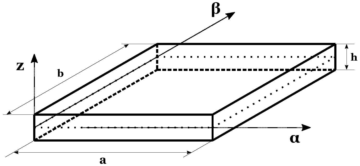
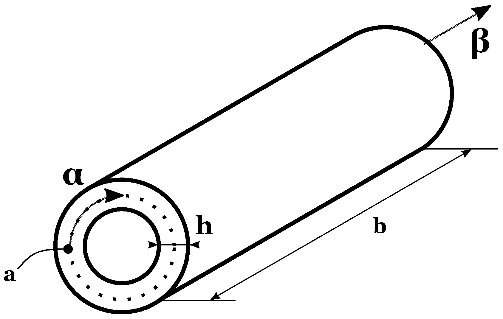
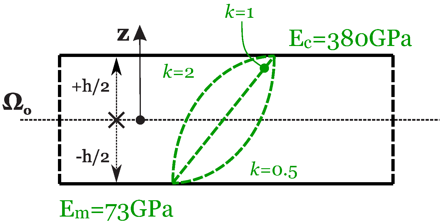
The results proposed in this section are given in order to identify the optimum for combined values of the M number of mathematical layers and the N order of expansion for the exponential matrix. The introduction of the mathematical layers is necessary to obtain constant coefficients in the equilibrium equations by approximating the FGM properties and the curvature terms for shells. Four different geometries are proposed. The first case considers a square plate, and geometry is shown in Figure 3. The in-plane dimensions are a = b = 1 m . Two different thickness ratios have been taken into account: a / h = 20 for the thinner plate and a / h = 4 for the thicker plate. Figure 4 shows the second geometry for the cylinder. The radius of curvature is infinite in β -direction ( R β = ) and it is finite in α direction ( R α = 10 m ). The α dimension of its middle surface is equal to a = 2 π R α , while the dimension in β direction is b = 20 m . The considered thickness ratios are R α / h = 10 and R α / h = 4 . Both the plate and the cylinder consider the same material configuration, a single FGM layer with a metallic and a ceramic phase. The Young modulus changes across the thickness with the following law:
E ( z ) = E m + ( E c E m ) V c .
E m is the Young modulus for the metallic phase and E c is the Young modulus for the ceramic phase. E m = 70 GPa and E c = 380 GPa are considered. V c is the volume fraction of the ceramic phase, and it is defined as:
V c = 2 z + h 2 h κ where h 2 z h 2 .
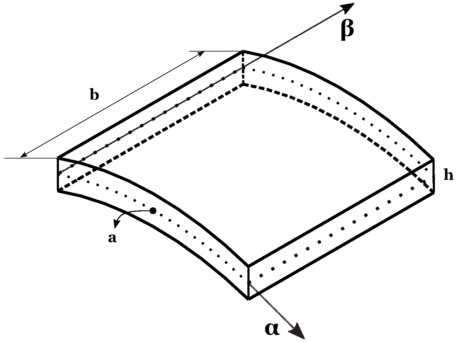
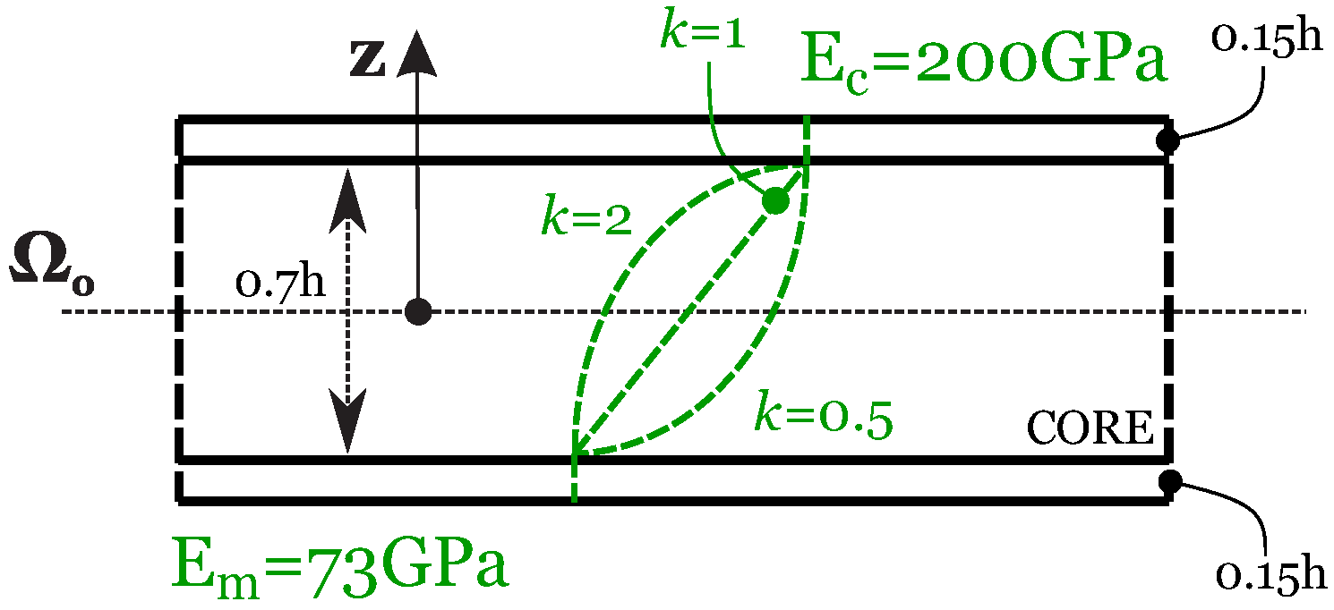
V c is zero at the bottom of the structure ( z = h 2 ), which means fully metallic, and it is equal to 1 at the top of the structure ( z = h 2 ), which means fully ceramic. κ is a parameter, which changes the volume fraction law across the thickness. It may be equal to 0 . 5 , 1 and 2 . In the first benchmark, κ = 0 . 5 is considered; in the second benchmark, a linear evolution of V c is chosen with κ = 1 . Figure 5 shows the evolution of the elastic properties through the thickness and the influence of the parameter κ . The Poisson ratio is constant through the thickness ( ν m = ν c = 0 . 3 ). This feature makes the Young modulus be the only quantity that changes through the thickness. The third geometry is presented in Figure 6 and it is a cylindrical shell panel. The only finite radius of curvature is the one in α direction, and it is equal to R α = 10 m . The following in-plane dimensions are taken into account: a = π 3 R α and b = 20 m . Figure 7 introduces the fourth and last geometry. A spherical shell panel is considered, having the same radii of curvature in both directions ( R α = R β = 10 m ). In addition, the in-plane dimensions are the same in the two directions and they are expressed in terms of R α as a = b = π 3 R α . Both the third and the fourth cases consider a sandwich configuration, with bottom and top isotropic skins and an FGM core. The thickness of the bottom skin is h 1 = 0 . 15 h , and it is full metallic with Young modulus E m = 70 GPa . The top skin is full ceramic with the Young modulus E c = 200 GPa . The top skin has the same thickness of the bottom skin ( h 3 = 0 . 15 h ). The FGM core has thickness h 2 = 0 . 7 h ; the Young modulus of this layer changes according to the same law presented in Equation (40). It changes from a fully metallic phase on the bottom to a fully ceramic phase on the top. As the mechanical properties only change in the range 0 . 7 h 2 z 0 . 7 h 2 , the thickness of the core ( h 2 = 0 . 7 h ) must replace the total thickness h in Equation (41). The parameter κ has been chosen equal to 2 in the case of the cylindrical shell and equal to 1 for the spherical panel. Figure 8 shows the material properties through the thickness for these last two shell geometries. The Poisson ratio remains constant through the thickness and it is equal to ν m = ν c = 0 . 3 . In both cases, a moderately thick ( R α / h = 10 ) and a thick shell ( R α / h = 4 ) are considered.
In all four of the cases, the load is applied on the top surface and in the z-direction; its amplitude is equal to 1 Pa . The considered half-wave numbers differ from case to case. Cases 1, 3 and 4 take into consideration ( m , n ) = ( 1 , 1 ) ; for the cylinder Case 2, ( m , n ) = ( 2 , 1 ) is set. The results shown in tables and figures are given in no-dimensional form. For the plates of Case 1, they are:
w ¯ = 10 4 E m w P z h ( a / h ) 4 , σ ¯ β z = σ β z P z ( a / h ) .
All the results for shells of Cases 2–4 are obtained using the following no-dimensional quantities:
{ u ¯ , v ¯ , w ¯ } = 10 4 E m { u , v , w } P z h ( R α / h ) 4 , σ ¯ α α = 10 2 σ α α P z ( R α / h ) 2 , σ ¯ α z = 10 2 σ α z P z ( R α / h ) , σ ¯ z z = σ z z .
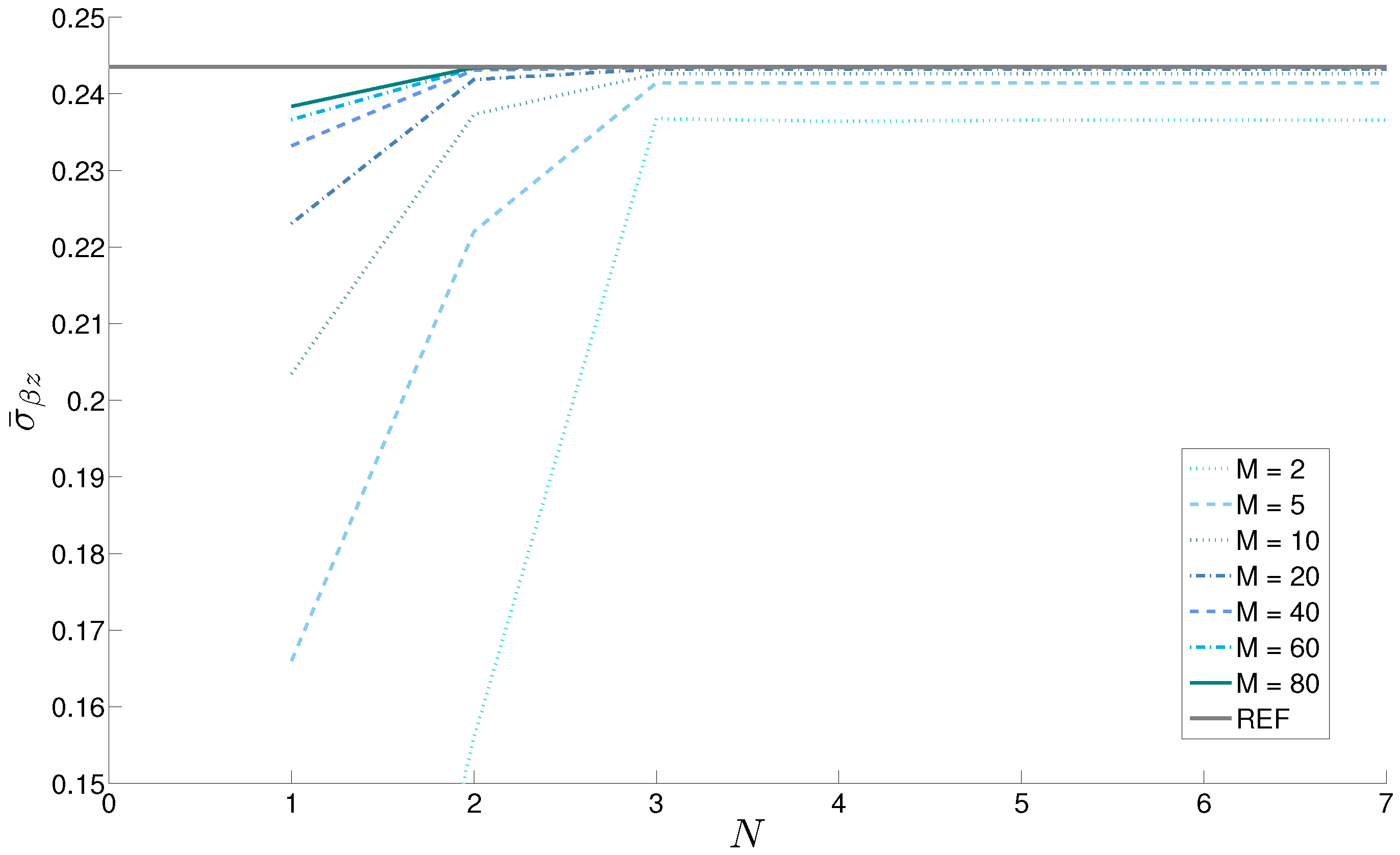
Table 1 summarizes the results obtained for the plate; the displacement w ¯ and the stress σ ¯ β z are shown. The displacement is given for the thicker plate ( a / h = 4 ); the stress is considered for the thinner one ( a / h = 20 ). In this case, the curvature-related terms are not present. However, the introduction of a certain number of mathematical layers is necessary to take into account the through-the-thickness law followed by the mechanical properties. The N order of expansion is ineffective in this sense because the exponential matrix of each layer contains the mechanical properties evaluated in the middle point of the layer. This effect is clear as by increasing the order of expansion N, the result converges at a correct value only for a minimum value of M. At least M = 60 mathematical layers are necessary for the thinner plate, while the thicker plate needs at least M = 250 layers to obtain correct results. Both cases must be combined with an N order of expansion equal to 3. Some of the results of Table 1 are also shown in Figure 9 for the thinner plate. The plots are drawn for different and increasing values of the number of mathematical layers (until M = 80 , which allows the convergence).
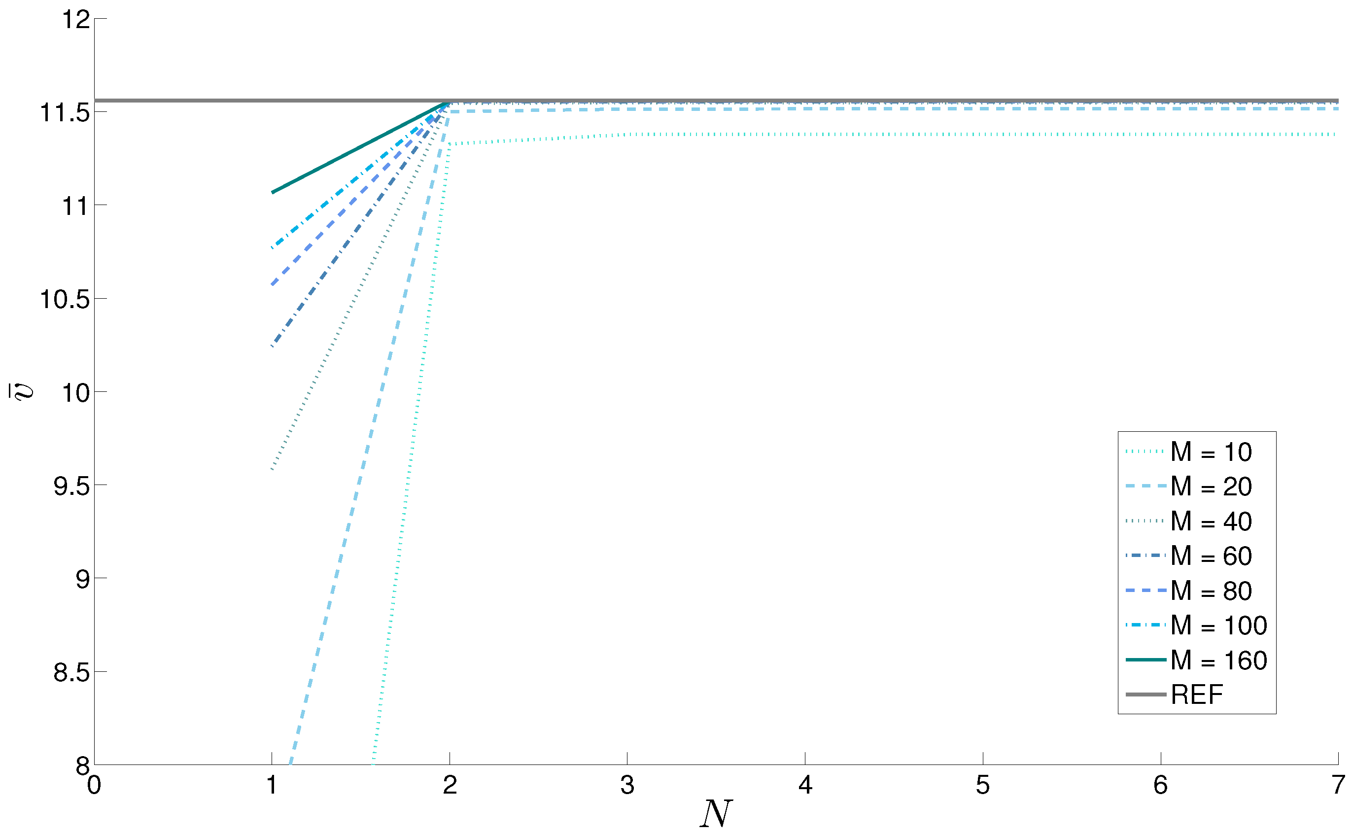
The displacement v ¯ and the stress σ ¯ z z are shown in Table 2 for the closed cylinder. The no-dimensional forms introduced in Equation (43) for these quantities have been considered. The results converge to the exact values faster than those for the plate case even if curvature terms are included in the cylinder. This feature is due to some advantages of this geometry and the relative lamination. First of all, an easier law for the mechanical characteristics (with κ = 1 , the elastic properties develop linearly through the thickness). Moreover, the geometry also plays an important role as the symmetry makes the problem easier to be solved and the closed geometry increases the rigidity of the structure. In the thinner case ( R α / h = 10 ), only M = 10 mathematical layers are necessary to stabilize the stress value (when it is coupled with a third-order of expansion for the exponential matrix). On the other side, the same order of expansion N = 3 needs at least M = 160 mathematical layers to obtain the convergence of the displacement v ¯ because a thicker shell is analyzed. Figure 10 confirms the trend shown in Table 2 for the displacement v ¯ of the thicker cylinder; the results move close to the exact value as the number M mathematical layers is increased. This result is achieved with only a third expansion order for the exponential matrix ( N = 3 ).
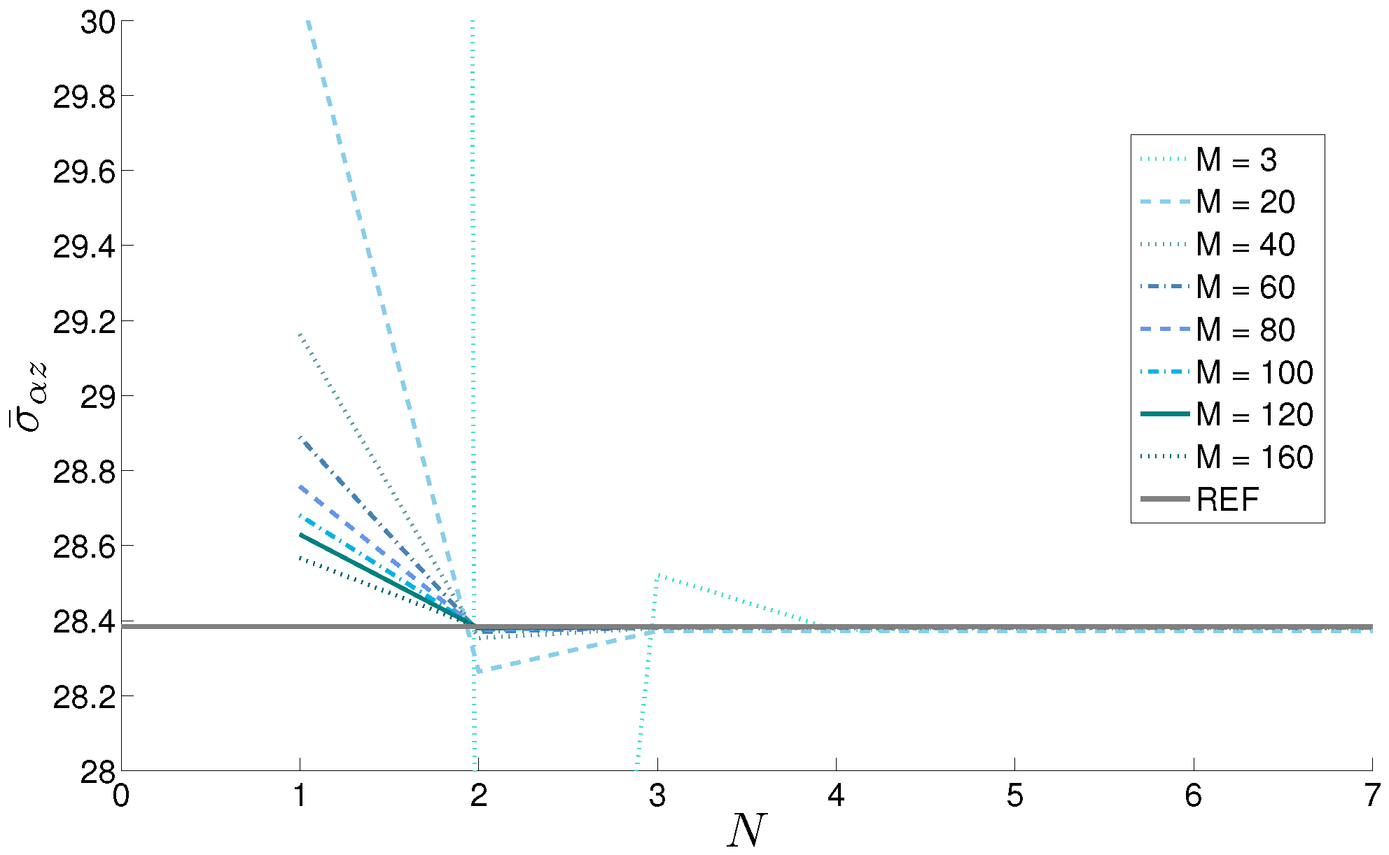
The results obtained for the sandwich cylindrical panel are shown in Table 3; the stress σ ¯ α z for the thinner shell ( R α / h = 10 ) and the displacement u ¯ for the thicker geometry ( R α / h = 4 ), are presented. The material property law follows a second-order evolution inside the core, while constant elastic properties through the thickness are considered for both the external skins. This case is interesting as it shows that the impact of different factors follows a behavior, which is a priori unpredictable. In the presented case, the concerned stress reaches the convergence with M = 160 mathematical layers, starting from an order of expansion N for the exponential matrix equal to 3. This result can be easily explained because the geometry and the lamination scheme are harder to be described than those presented in the previous case (cylinder). On the contrary, the displacement u ¯ , which is a direct output for the proposed solution, converges using only M = 40 with the same order of expansion ( N = 3 ), even if a thicker plate is considered. The convergence of the stress σ ¯ α z with increasing values of M is shown in Figure 11.
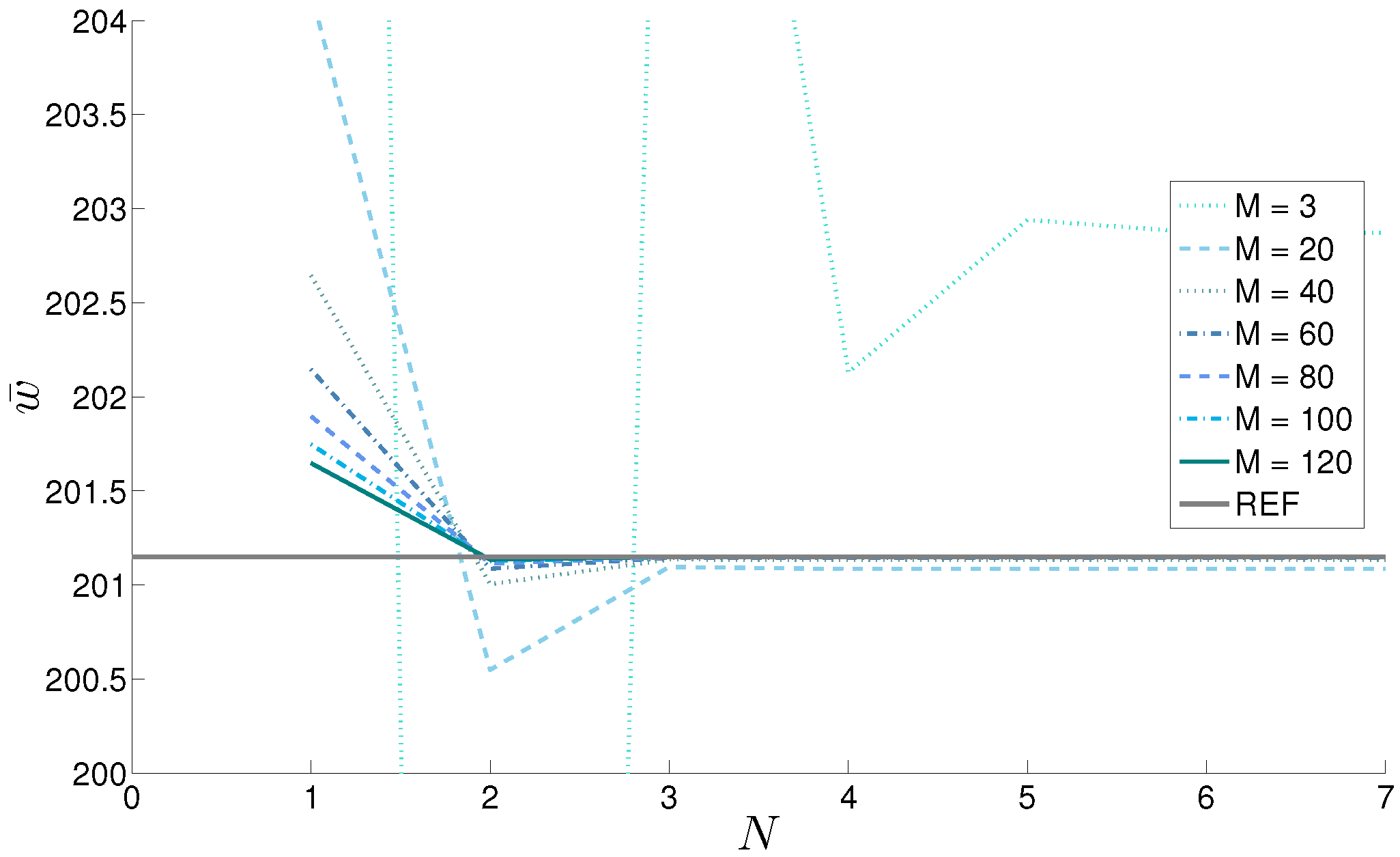
The results for the last considered geometry are presented in Table 4 where a sandwich spherical shell panel is analyzed. The through-the-thickness law for the elastic properties is simpler because the volume fraction in the FGM core follows a linear evolution with respect to z ( κ = 1 ). The stress σ ¯ α α is considered for the thicker structure. The second-order expansion combined with M = 40 guarantees the convergence. N = 3 expansion order allows the number of mathematical layers to be further reduced until M = 20 . The thicker case ( R α / h = 4 ) also shows that the number of mathematical layers can be strongly reduced when the order of expansion is increased. Passing from N = 2 to N = 3 , the mathematical layers can be reduced from M = 200 to M = 80 . The results presented in Table 4 are shown in Figure 12 for the displacement w ¯ with a progressive increase of the number of mathematical layers until M = 120 .

4. Conclusions

The present paper proposes the 3D equilibrium equations in mixed orthogonal curvilinear coordinates to perform the 3D exact static solution of plates and shells with Functionally Graded Material (FGM) layers. The problem is solved for different kinds of geometry: plates, cylinders, spherical and cylindrical shells can be analyzed via a unique formulation. The second order differential equations are reduced to the first order differential equations redoubling the number of variables. The system of first order equations is solved through the thickness using the exponential matrix method. This method allows for obtaining as a direct result the displacement amplitudes and the relative derivatives with respect to z. The coefficients of the differential equations are not constant as they depend on the thickness coordinate. This dependence is related to the material (as the mechanical properties of FGM layers change across the thickness) and to the geometry (as the curvature is considered by means of parametric coefficients). The structures are divided into M mathematical layers to approximate these values in the middle of each layer. The third order of expansion for the exponential matrix combined with the opportune value of M always give stable results. Several parameters play a significant role in the definition of these values, but these effects cannot be a priori determined. The complexity of the FGM law is one of the most important parameters. The influence of geometry and thickness ratio is also fundamental. Using an expansion N = 3 combined with M = 300 mathematical layers, the convergence to the exact results for each possible case is always guaranteed.

Author Contributions

Salvatore Brischetto implemented the analytical code; Roberto Torre analyzed the data; Salvatore Brischetto and Roberto Torre wrote the paper.

Conflicts of Interest

The authors declare no conflict of interest.

References

  1. Wessel, J.K. The Handbook of Advanced Materials; John Wiley & Sons: Hoboken, NJ, USA, 2004. [Google Scholar]
  2. Mahamood, R.M.; Akinlabi, E.T. Functionally Graded Materials; Springer: Heidelberg, Germany, 2017. [Google Scholar]
  3. Ichikawa, K. Functionally Graded Materials in the 21st Century; Springer: Heidelberg, Germany, 2001. [Google Scholar]
  4. Kashtalyan, M. Three-dimensional elasticity solution for bending of functionally graded rectangular plates. Eur. J. Mech. 2004, 23, 853–864. [Google Scholar] [CrossRef]
  5. Plevako, V.P. On the theory of elasticity of inhomogeneous media. J. Appl. Math. Mech. 1971, 35, 806–813. [Google Scholar] [CrossRef]
  6. Vel, S.S.; Batra, R.C. Three-dimensional exact solution for the vibration of functionally graded rectangular plates. J. Sound Vib. 2004, 272, 703–730. [Google Scholar] [CrossRef]
  7. Xu, Y.; Zhou, D. Three-dimensional elasticity solution of functionally graded rectangular plates with variable thickness. Compos. Struct. 2009, 91, 56–65. [Google Scholar] [CrossRef]
  8. Yas, M.H.; Tahouneh, V. 3-D Free vibration analysis of thick functionally graded annular plates on Pasternak elastic foundation via differential quadrature method (DQM). Acta Mech. 2012, 223, 43–62. [Google Scholar] [CrossRef]
  9. Zhong, Z.; Shang, E.T. Three-dimensional exact analysis of a simply supported functionally gradient piezoelectric plate. Int. J. Solids Struct. 2003, 40, 5335–5352. [Google Scholar] [CrossRef]
  10. Hosseini-Hashemi, S.; Salehipour, H.; Atashipour, S.R. Exact three-dimensional free vibration analysis of thick homogeneous plates coated by a functionally graded layer. Acta Mech. 2012, 223, 2153–2166. [Google Scholar] [CrossRef]
  11. Li, Q.; Iu, V.P.; Kou, K.P. Three-dimensional vibration analysis of functionally graded material sandwich plates. J. Sound Vib. 2008, 311, 498–515. [Google Scholar] [CrossRef]
  12. Zahedinejad, P.; Malekzadeh, P.; Farid, M.; Karami, G. A semi-analytical three-dimensional free vibration analysis of functionally graded curved panels. Int. J. Press. Vessel. Pip. 2010, 87, 470–480. [Google Scholar] [CrossRef]
  13. Alibeigloo, A.; Kani, A.M.; Pashaei, M.H. Elasticity solution for the free vibration analysis of functionally graded cylindrical shell bonded to thin piezoelectric layers. Int. J. Press. Vessel. Pip. 2012, 89, 98–111. [Google Scholar] [CrossRef]
  14. Vel, S.S. Exact elasticity solution for the vibration of functionally graded anisotropic cylindrical shells. Compos. Struct. 2010, 92, 2712–2727. [Google Scholar] [CrossRef]
  15. Dong, C.Y. Three-dimensional free vibration analysis of functionally graded annular plates using the Chebyshev-Ritz method. Mater. Des. 2008, 29, 1518–1525. [Google Scholar] [CrossRef]
  16. Kashtalyan, M.; Menshykova, M. Three-dimensional elasticity solution for sandwich panels with a functionally graded core. Compos. Struct. 2009, 87, 36–43. [Google Scholar] [CrossRef]
  17. Barretta, R. Analogies between Kirchhoff plates and Saint-Venant beams under torsion. Acta Mech. 2013, 224, 2955–2964. [Google Scholar] [CrossRef]
  18. Barretta, R. Analogies between Kirchhoff plates and Saint-Venant beams under flexure. Acta Mech. 2014, 225, 2075–2083. [Google Scholar] [CrossRef]
  19. Barretta, R.; Luciano, R. Analogies between Kirchhoff plates and functionally graded Saint-Venant beams under torsion. Contin. Mech. Thermodyn. 2014, 27, 449–505. [Google Scholar] [CrossRef]
  20. Barretta, R. On Cesáro-Volterra Method in Orthotropic Saint-Venant Beam. J. Elast. 2013, 112, 233–253. [Google Scholar] [CrossRef]
  21. Barretta, R. On the relative position of twist and shear centres in the orthotropic and fiberwise homogeneous Saint–Venant beam theory. Acta Mech. 2012, 49, 3038–3046. [Google Scholar] [CrossRef]
  22. Brischetto, S. Exact elasticity solution for natural frequencies of functionally graded simply-supported structures. CMES Comput. Mod. Eng. Sci. 2013, 95, 391–430. [Google Scholar]
  23. Brischetto, S. A general exact elastic shell solution for bending analysis of functionally graded structures. Compos. Struct. 2017, 175, 70–85. [Google Scholar] [CrossRef]
  24. Brischetto, S. Convergence analysis of the exponential matrix method for the solution of 3D equilibrium equations for free vibration analysis of plates and shells. Compos. Part B Eng. 2016, 98, 453–471. [Google Scholar] [CrossRef]
  25. Brischetto, S. Exponential matrix method for the solution of exact 3D equilibrium equations for free vibrations of functionally graded plates and shells. J. Sandw. Struct. Mater. 2017. [CrossRef]
  26. Brischetto, S.; Torre, R. Convergence investigation for the exponential matrix and mathematical layers in the static analysis of multilayered composite structures. J. Compos. Sci. 2017, 1, 19. [Google Scholar] [CrossRef]
  27. Hildebrand, F.B.; Reissner, E.; Thomas, G.B. Notes on the Foundations of the Theory of Small Displacements of Orthotropic Shells; NACA Technical Note No. 1833; National Advisory Committee for Aeronautics: Washington, DC, USA, 1949. [Google Scholar]
  28. Soedel, W. Vibration of Shells and Plates; Marcel Dekker, Inc.: New York, NY, USA, 2004. [Google Scholar]
  29. Tornabene, F. Meccanica delle Strutture a Guscio in Materiale Composito; Società Editrice Esculapio: Bologna, Italy, 2012. [Google Scholar]
  30. Gustafson, G.B. Systems of Differential Equations. Available online: http://www.math.utah.edu/gustafso/2250systems-de.pdf (accessed on 7 March 2016).
  31. Boyce, W.E.; DiPrima, R.C. Elementary Differential Equations and Boundary Value Problems; John Wiley & Sons, Ltd.: New York, NY, USA, 2001. [Google Scholar]
  32. Molery, C.; Van Loan, C. Nineteen dubious ways to compute the exponential of a matrix, twenty-five years later. SIAM Rev. 2003, 45, 1–46. [Google Scholar] [CrossRef]
  33. Brischetto, S. Exact three-dimensional static analysis of single- and multi-layered plates and shells. Compos. Part B Eng. 2017, 119, 230–252. [Google Scholar] [CrossRef]
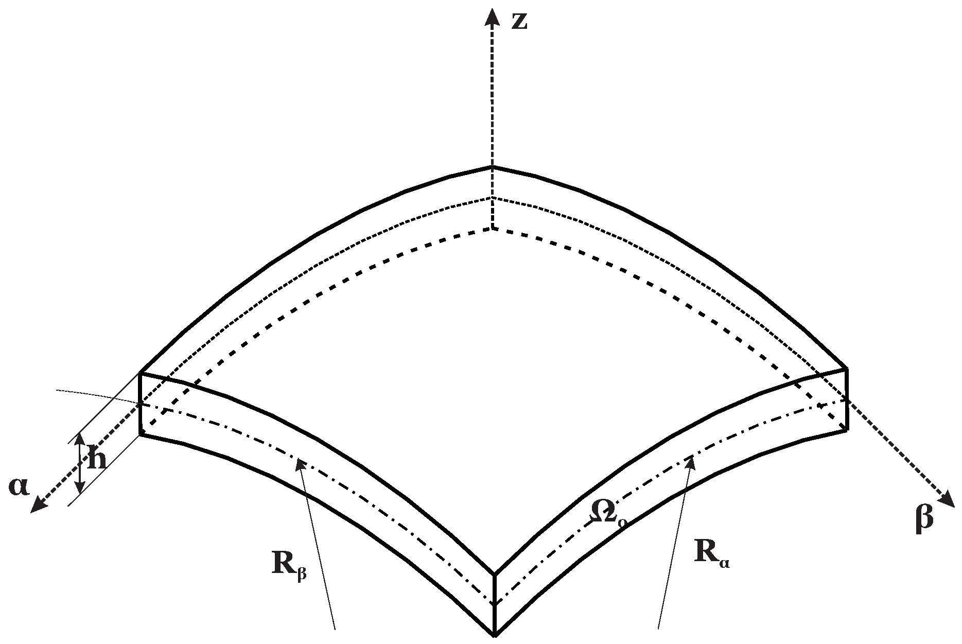
Figure 1. Reference system and notations for the generic shell element.
Applsci 08 00110 g001
Figure 2. Thickness coordinates for the generic shell element.
Applsci 08 00110 g002
Figure 3. The square plate geometry for Case 1.
Applsci 08 00110 g003
Figure 4. The cylinder geometry for Case 2.
Applsci 08 00110 g004
Figure 5. Functionally Graded Material (FGM) configuration and elastic properties for Cases 1 and 2.
Applsci 08 00110 g005
Figure 6. The cylindrical shell geometry for Case 3.
Applsci 08 00110 g006
Figure 7. The spherical shell geometry for Case 4.
Applsci 08 00110 g007
Figure 8. FGM configuration and elastic properties for Cases 3 and 4.
Applsci 08 00110 g008
Figure 9. Case 1, one-layered FGM ( κ = 0 . 5 ) plate with thickness ratio a / h = 20 . Stress σ ¯ β z ( a / 2 , 0 , 0 ) vs. N order of expansion of the exponential matrix for different M numbers of global mathematical layers. Reference solution in Brischetto [23] is here indicated as REF.
Applsci 08 00110 g009
Figure 10. Case 2, one-layered FGM ( κ = 1 ) cylinder with thickness ratio R α / h = 4 . Displacement v ¯ ( a / 2 , 0 , 0 ) vs. N order of expansion of the exponential matrix for different M numbers of global mathematical layers. Reference solution in Brischetto [23] is here indicated as REF.
Applsci 08 00110 g010
Figure 11. Case 3, sandwich cylindrical shell with FGM ( κ = 2 ) core and thickness ratio R α / h = 10 . Stress σ ¯ α z ( 0 , b / 2 , 0 ) vs. N order of expansion of the exponential matrix for different M numbers of global mathematical layers. Reference solution in Brischetto [23] is here indicated as REF.
Applsci 08 00110 g011
Figure 12. Case 4, sandwich spherical shell with FGM ( κ = 1 ) core and thickness ratio R α / h = 4 . Displacement w ¯ ( a / 2 , b / 2 , 0 ) vs. N order of expansion of the exponential matrix for different M numbers of global mathematical layers. Reference solution in Brischetto [23] is here indicated as REF.
Applsci 08 00110 g012
Table 1. Case 1, one-layered Functionally Graded Material (FGM) ( κ = 0 . 5 ) plate. Displacement w ¯ for thickness ratio a / h = 4 and stress σ ¯ β z for thickness ratio a / h = 20 , both evaluated in the middle of the thickness and given as dimensionless values. One physical layer ( N L = 1) divided into M global mathematical layers. 3D reference solution in Brischetto [23]. NaN means Not a Number. Digits given in bold are the correct values.
w ¯ ( a / 2 , b / 2 , 0 ) ; a / h = 4
N = 1 N = 2 N = 3 N = 4 N = 5 N = 6 N = 7 N = 8 N = 9 N = 10 N = 11 N = 12
M = 1 NaN25.06587.8068.8998.2690.8092.3692.1592.1892.1892.1892.18
M = 2 108.4366.33103.6796.7098.3298.2298.2398.2398.2398.2398.2398.23
M = 5 105.1896.78103.35103.18103.22103.22103.22103.22103.22103.22103.22103.22
M = 10 105.54103.06104.77104.76104.77104.77104.77104.77104.77104.77104.77104.77
M = 20 105.66104.92105.35105.35105.35105.35105.35105.35105.35105.35105.35105.35
M = 40 105.70105.45105.56105.56105.56105.56105.56105.56105.56105.56105.56105.56
M = 60 105.70105.56105.61105.61105.61105.61105.61105.61105.61105.61105.61105.61
M = 80 105.70105.61105.63105.63105.63105.63105.63105.63105.63105.63105.63105.63
M = 100 105.69105.63105.65105.65105.65105.65105.65105.65105.65105.65105.65105.65
M = 130 105.69105.64105.65105.65105.65105.65105.65105.65105.65105.65105.65105.65
M = 160 105.69105.65105.66105.66105.66105.66105.66105.66105.66105.66105.66105.66
M = 200 105.69105.66105.66105.66105.66105.66105.66105.66105.66105.66105.66105.66
M = 250 105.68105.66105.67105.67105.67105.67105.67105.67105.67105.67105.67105.67
M = 300 105.68105.67105.67105.67105.67105.67105.67105.67105.67105.67105.67105.67
M = 350 105.67105.67105.67105.67105.67105.67105.67105.67105.67105.67105.67105.67
M = 400 105.67105.67105.67105.67105.67105.67105.67105.67105.67105.67105.67105.67
σ ¯ β z ( a / 2 , 0 , 0 ) ; a / h = 20
N = 1 N = 2 N = 3 N = 4 N = 5 N = 6 N = 7 N = 8 N = 9 N = 10 N = 11 N = 12
M = 1 NaN0.08020.24480.23680.23910.23910.23910.23910.23910.23910.23910.2391
M = 2 0.05410.15600.23670.23640.23650.23650.23650.23650.23650.23650.23650.2365
M = 5 0.16600.22200.24140.24140.24140.24140.24140.24140.24140.24140.24140.2414
M = 10 0.20350.23730.24260.24260.24260.24260.24260.24260.24260.24260.24260.2426
M = 20 0.22310.24190.24320.24320.24320.24320.24320.24320.24320.24320.24320.2432
M = 40 0.23320.24310.24340.24340.24340.24340.24340.24340.24340.24340.24340.2434
M = 60 0.23660.24330.24350.24350.24350.24350.24350.24350.24350.24350.24350.2435
M = 80 0.23840.24340.24350.24350.24350.24350.24350.24350.24350.24350.24350.2435
M = 100 0.23940.24350.24350.24350.24350.24350.24350.24350.24350.24350.24350.2435
M = 130 0.24030.24350.24350.24350.24350.24350.24350.24350.24350.24350.24350.2435
M = 160 0.24090.24350.24350.24350.24350.24350.24350.24350.24350.24350.24350.2435
M = 200 0.24150.24350.24350.24350.24350.24350.24350.24350.24350.24350.24350.2435
M = 250 0.24190.24350.24350.24350.24350.24350.24350.24350.24350.24350.24350.2435
M = 300 0.24220.24350.24350.24350.24350.24350.24350.24350.24350.24350.24350.2435
M = 350 0.24240.24350.24350.24350.24350.24350.24350.24350.24350.24350.24350.2435
M = 400 0.24250.24350.24350.24350.24350.24350.24350.24350.24350.24350.24350.2435
Table 2. Case 2, one-layered FGM ( κ = 1 ) cylinder. Displacement v ¯ for thickness ratio R α / h = 4 and stress σ ¯ z z for thickness ratio R α / h = 10 , both evaluated in the middle of the thickness and given as dimensionless values. One physical layer ( N L = 1) divided into M global mathematical layers. 3D reference solution in Brischetto [23]. Digits given in bold are the correct values.
v ¯ ( a / 2 , 0 , 0 ) ; R α / h = 4
N = 1 N = 2 N = 3 N = 4 N = 5 N = 6 N = 7 N = 8 N = 9 N = 10 N = 11 N = 12
M = 1 91 . 308 0.273 11 . 682 7 . 335 7 . 671 7 . 630 7 . 631 7 . 631 7 . 631 7 . 631 7 . 631 7 . 631
M = 2 31 . 308 6.9196.7767.0787.7077.7077.7077.7077.7077.7077.7077.707
M = 5 4 . 599 10.60110.75910.77610.77610.77610.77610.77610.77610.77610.77610.776
M = 10 3.60311.32611.37711.37911.37911.37911.37911.37911.37911.37911.37911.379
M = 20 7.60011.50011.51411.51411.51411.51411.51411.51411.51411.51411.51411.514
M = 40 9.58411.54411.54811.54811.54811.54811.54811.54811.54811.54811.54811.548
M = 60 10.24311.55311.55411.55411.55411.55411.55411.55411.55411.55411.55411.554
M = 80 10.57211.55611.55611.55611.55611.55611.55611.55611.55611.55611.55611.556
M = 100 10.77011.55711.55711.55711.55711.55711.55711.55711.55711.55711.55711.557
M = 130 10.95211.55811.55811.55811.55811.55811.55811.55811.55811.55811.55811.558
M = 160 11.06611.55811.55911.55911.55911.55911.55911.55911.55911.55911.55911.559
M = 200 11.16511.55911.55911.55911.55911.55911.55911.55911.55911.55911.55911.559
M = 250 11.24411.55911.55911.55911.55911.55911.55911.55911.55911.55911.55911.559
M = 300 11.29611.55911.55911.55911.55911.55911.55911.55911.55911.55911.55911.559
M = 350 11.33411.55911.55911.55911.55911.55911.55911.55911.55911.55911.55911.559
M = 400 11.36211.55911.55911.55911.55911.55911.55911.55911.55911.55911.55911.559
σ ¯ zz ( a / 2 , b / 2 , 0 ) ; R α / h = 10
N = 1 N = 2 N = 3 N = 4 N = 5 N = 6 N = 7 N = 8 N = 9 N = 10 N = 11 N = 12
M = 1 0.51180.44560.47230.46990.47010.47010.47010.47010.47010.47010.47010.4701
M = 2 0.34570.32920.33330.33310.33310.33310.33310.33310.33310.33310.33310.3331
M = 5 0.34320.33760.33820.33820.33820.33820.33820.33820.33820.33820.33820.3382
M = 10 0.33510.33260.33270.33270.33270.33270.33270.33270.33270.33270.33270.3327
M = 20 0.33390.33270.33270.33270.33270.33270.33270.33270.33270.33270.33270.3327
M = 40 0.33330.33270.33270.33270.33270.33270.33270.33270.33270.33270.33270.3327
M = 60 0.33310.33270.33270.33270.33270.33270.33270.33270.33270.33270.33270.3327
M = 80 0.3330.33270.33270.33270.33270.33270.33270.33270.33270.33270.33270.3327
M = 100 0.33290.33270.33270.33270.33270.33270.33270.33270.33270.33270.33270.3327
M = 130 0.33290.33270.33270.33270.33270.33270.33270.33270.33270.33270.33270.3327
M = 160 0.33280.33270.33270.33270.33270.33270.33270.33270.33270.33270.33270.3327
M = 200 0.33280.33270.33270.33270.33270.33270.33270.33270.33270.33270.33270.3327
M = 250 0.33280.33270.33270.33270.33270.33270.33270.33270.33270.33270.33270.3327
M = 300 0.33280.33270.33270.33270.33270.33270.33270.33270.33270.33270.33270.3327
M = 350 0.33280.33270.33270.33270.33270.33270.33270.33270.33270.33270.33270.3327
M = 400 0.33280.33270.33270.33270.33270.33270.33270.33270.33270.33270.33270.3327
Table 3. Case 3, sandwich cylindrical shell with FGM ( κ = 2 ) core. Displacement u ¯ for thickness ratio R α / h = 4 and stress σ ¯ α z for thickness ratio R α / h = 10 , both evaluated in the middle of the thickness and given as dimensionless values. Three physical layers ( N L = 3) divided into M global mathematical layers. 3D reference solution in Brischetto [23]. Digits given in bold are the correct values.
u ¯ ( 0 , b / 2 , 0 ) ; R α / h = 4
N = 1 N = 2 N = 3 N = 4 N = 5 N = 6 N = 7 N = 8 N = 9 N = 10 N = 11 N = 12
M = 3 469.72246.78320.81312.72313.62313.57313.58313.58313.58313.58313.58313.58
M = 20 329.32319.37320.96320.95320.95320.95320.95320.95320.95320.95320.95320.95
M = 40 324.87320.57320.96320.96320.96320.96320.96320.96320.96320.96320.96320.96
M = 60 323.51320.79320.96320.96320.96320.96320.96320.96320.96320.96320.96320.96
M = 80 322.85320.87320.96320.96320.96320.96320.96320.96320.96320.96320.96320.96
M = 100 322.46320.90320.96320.96320.96320.96320.96320.96320.96320.96320.96320.96
M = 120 322.21320.92320.96320.96320.96320.96320.96320.96320.96320.96320.96320.96
M = 140 322.03320.93320.96320.96320.96320.96320.96320.96320.96320.96320.96320.96
M = 160 321.89320.94320.96320.96320.96320.96320.96320.96320.96320.96320.96320.96
M = 200 321.70320.95320.96320.96320.96320.96320.96320.96320.96320.96320.96320.96
M = 240 321.58320.95320.96320.96320.96320.96320.96320.96320.96320.96320.96320.96
M = 260 321.53320.95320.96320.96320.96320.96320.96320.96320.96320.96320.96320.96
M = 300 321.45320.96320.96320.96320.96320.96320.96320.96320.96320.96320.96320.96
M = 340 321.40320.96320.96320.96320.96320.96320.96320.96320.96320.96320.96320.96
M = 400 321.33320.96320.96320.96320.96320.96320.96320.96320.96320.96320.96320.96
σ ¯ α z ( 0 , b / 2 , 0 ) ; R α / h = 10
N = 1 N = 2 N = 3 N = 4 N = 5 N = 6 N = 7 N = 8 N = 9 N = 10 N = 11 N = 12
M = 3 191.6024.04128.52228.37528.38328.38328.38328.38328.38328.38328.38328.383
M = 20 30.08128.26528.37328.37328.37328.37328.37328.37328.37328.37328.37328.373
M = 40 29.16328.35428.38128.38128.38128.38128.38128.38128.38128.38128.38128.381
M = 60 28.88928.37128.38228.38228.38228.38228.38228.38228.38228.38228.38228.382
M = 80 28.75828.37628.38328.38328.38328.38328.38328.38328.38328.38328.38328.383
M = 100 28.68128.37928.38328.38328.38328.38328.38328.38328.38328.38328.38328.383
M = 120 28.63028.38028.38328.38328.38328.38328.38328.38328.38328.38328.38328.383
M = 140 28.59428.38128.38328.38328.38328.38328.38328.38328.38328.38328.38328.383
M = 160 28.56728.38228.38428.38428.38428.38428.38428.38428.38428.38428.38428.384
M = 200 28.53028.38328.38428.38428.38428.38428.38428.38428.38428.38428.38428.384
M = 240 28.50528.38328.38428.38428.38428.38428.38428.38428.38428.38428.38428.384
M = 260 28.49628.38328.38428.38428.38428.38428.38428.38428.38428.38428.38428.384
M = 300 28.48128.38328.38428.38428.38428.38428.38428.38428.38428.38428.38428.384
M = 340 28.46928.38328.38428.38428.38428.38428.38428.38428.38428.38428.38428.384
M = 400 28.45628.38328.38428.38428.38428.38428.38428.38428.38428.38428.38428.384
Table 4. Case 4, sandwich spherical shell with FGM ( κ = 1 ) core. Displacement w ¯ in the middle of the thickness for thickness ratio R α / h = 4 and stress σ ¯ α α at the top surface for thickness ratio R α / h = 10 , both given as dimensionless values. Three physical layers ( N L = 3) divided into M global mathematical layers. 3D reference solution in Brischetto [23]. Digits given in bold are the correct values.
w ¯ ( a / 2 , b / 2 , 0 ) ; R α / h = 4
N = 1 N = 2 N = 3 N = 4 N = 5 N = 6 N = 7 N = 8 N = 9 N = 10 N = 11 N = 12
M = 3 228.39172.20208.31202.13202.94202.87202.87202.87202.87202.87202.87202.87
M = 20 204.15200.55201.10201.08201.08201.08201.08201.08201.08201.08201.08201.08
M = 40 202.64201.00201.14201.13201.13201.13201.13201.13201.13201.13201.13201.13
M = 60 202.14201.09201.14201.14201.14201.14201.14201.14201.14201.14201.14201.14
M = 80 201.90201.11201.15201.15201.15201.15201.15201.15201.15201.15201.15201.15
M = 100 201.75201.13201.15201.15201.15201.15201.15201.15201.15201.15201.15201.15
M = 120 201.65201.13201.15201.15201.15201.15201.15201.15201.15201.15201.15201.15
M = 140 201.58201.14201.15201.15201.15201.15201.15201.15201.15201.15201.15201.15
M = 160 201.52201.14201.15201.15201.15201.15201.15201.15201.15201.15201.15201.15
M = 200 201.45201.15201.15201.15201.15201.15201.15201.15201.15201.15201.15201.15
M = 240 201.40201.15201.15201.15201.15201.15201.15201.15201.15201.15201.15201.15
M = 260 201.38201.15201.15201.15201.15201.15201.15201.15201.15201.15201.15201.15
M = 300 201.35201.15201.15201.15201.15201.15201.15201.15201.15201.15201.15201.15
M = 340 201.33201.15201.15201.15201.15201.15201.15201.15201.15201.15201.15201.15
M = 400 201.30201.15201.15201.15201.15201.15201.15201.15201.15201.15201.15201.15
σ ¯ α α ( a / 2 , b / 2 , h / 2 ) ; R α / h = 10
N = 1 N = 2 N = 3 N = 4 N = 5 N = 6 N = 7 N = 8 N = 9 N = 10 N = 11 N = 12
M = 3 17.7511.2711.9911.9411.9411.9411.9411.9411.9411.9411.9411.94
M = 20 12.7212.0212.0312.0312.0312.0312.0312.0312.0312.0312.0312.03
M = 40 12.3712.0312.0312.0312.0312.0312.0312.0312.0312.0312.0312.03
M = 60 12.2612.0312.0312.0312.0312.0312.0312.0312.0312.0312.0312.03
M = 80 12.2012.0312.0312.0312.0312.0312.0312.0312.0312.0312.0312.03
M = 100 12.1612.0312.0312.0312.0312.0312.0312.0312.0312.0312.0312.03
M = 120 12.1412.0312.0312.0312.0312.0312.0312.0312.0312.0312.0312.03
M = 140 12.1312.0312.0312.0312.0312.0312.0312.0312.0312.0312.0312.03
M = 160 12.1112.0312.0312.0312.0312.0312.0312.0312.0312.0312.0312.03
M = 200 12.1012.0312.0312.0312.0312.0312.0312.0312.0312.0312.0312.03
M = 240 12.0912.0312.0312.0312.0312.0312.0312.0312.0312.0312.0312.03
M = 260 12.0812.0312.0312.0312.0312.0312.0312.0312.0312.0312.0312.03
M = 300 12.0712.0312.0312.0312.0312.0312.0312.0312.0312.0312.0312.03
M = 340 12.0712.0312.0312.0312.0312.0312.0312.0312.0312.0312.0312.03
M = 400 12.0612.0312.0312.0312.0312.0312.0312.0312.0312.0312.0312.03