
Calculation of the Center of Mass Position of Each Link of Multibody Biped Robots


Abstract
:1. Introduction
- PHASE 1—Determination of the technical specifications which define limits and characteristics that the robot should have.
- PHASE 2—Conceptual design of the robot including analysis of the developed robots in the world; design of novel systems; definition of the whole system including mechanics, electronics, low and high level control.
- PHASE 3—Functional design of the robot including interaction of the robot with the environment; theoretical formulation and optimization; software and hardware design of virtual models (virtual model prototyping using CAD tools, analytical simulations, finite elements analysis, multibody analysis).
- PHASE 4—Development of the robot including rapid prototyping modeling and tests.
- PHASE 5—Realization of the final robot prototype and final tests.
2. First Validated Theoretical Formulation
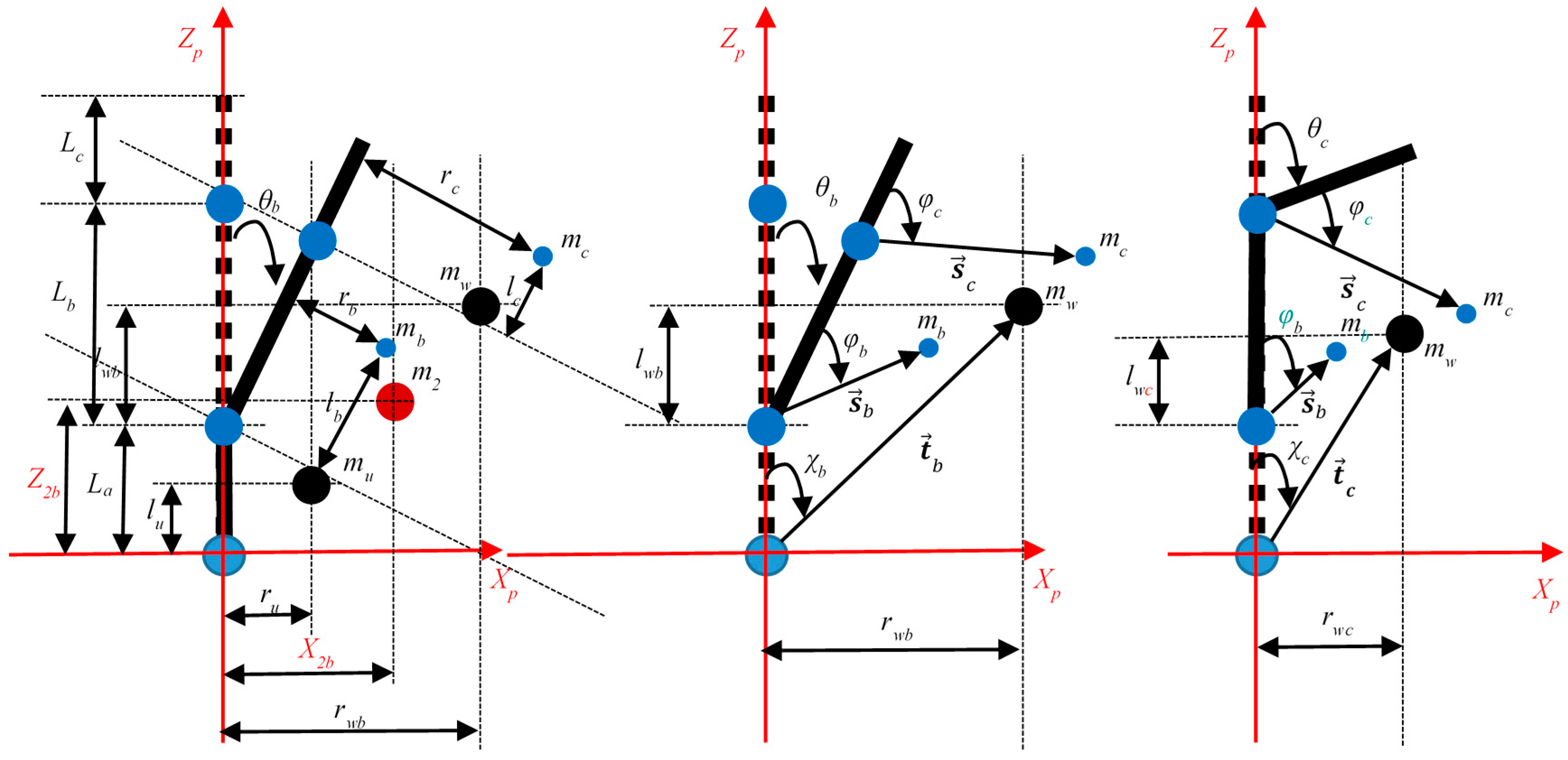
2.1. Dynamics of Multibody Biped Robots
2.2. Equilibrium
2.3. Proposed Coefficients
2.4. Determination of the Partial Center of Mass Position
3. Second Theoretical Formulation
3.1. Procedure for n Degrees of Freedom
3.2. Procedure for n = 2 Degrees of Freedom
- The robot is placed on a walking surface and the platform should be kept in a first balance configuration j allowing a measurement of the forces () and the torques () by means of the force-torque sensors on the feet, and of the armature currents (, , ). These values are used to calculate the coefficients of the (22) using respectively (10)–(13);
- The robot is placed in a second and third balance configuration i, and in the same way, forces, torques, and motor currents associated with each balance configuration (second and third) are measured. These values are used to calculate the coefficients using respectively (10)–(13).
- For each balance configuration i, the total CoM position is calculated using (22);
- Each total CoM position allows to determine rwi, qwi, lwi, using (23) and the CoM position of each link of the robot using (27). For each configuration i, an equation using (26) is created. n linearly independent equations are used to find n vector positions.
3.3. Implementation of the Analytical Formulation
- Only two force-torque sensors must be the contact elements between the robot and the ground;
- Joint sensors must give relative position of motion and current values to produce join motion.
4. Validation of the Second Theoretical Formulation
4.1. Example
4.2. Validation
- % MATLAB Example
- thb = 10 *pi/180; %radiant angle of the link Lb
- thc = 10 *pi/180; %radiant angle of the link Lc
- ma = 6.72; %kg weight of the Foot
- mb = 0.95; %kg weight of the link b
- mc = 1.16 + 0.94; %kg weight of the link c
- mw = mb + mc; %kg
- m2 = mu + mw; %kg
- ra = 0; %mm position of the CoM of the foot
- la = 26.32; %mm position of the CoM of the foot
- La = 100; %mm length of the foot in Zp direction
- Lb = 400; %mm length of the shin in Zp direction
- Lc = 500; %mm length of the thigh in Zp direction
- lb = 200; %mm INPUT CONDITION FOR VALIDATION
- lc = 250; %mm INPUT CONDITION FOR VALIDATION
- Z2a = (1/m2) *(ma *la + mb * (La + lb) + mc * (La + Lb + lc)); %mm Total CoM position in the configuration a
- X2a = 0; %mm Total CoM position in the configuration a
- Z2b = (1/m2) *(ma *la + mb * (La + lb *cos (thb)) + mc *(La + (Lb + lc) *cos (thb))); %mm Total CoM position in the configuration b
- X2b = (1/m2) *(mb *lb *sin (thb) + mc *(Lb + lc) *sin (thb)); %mm Total CoM position in the configuration b
- Z2c = (1/m2) *(ma *la + mb *(La + lb) + mc * (La + Lb + lc *cos (thc))); %mm Total CoM position in the configuration c
- X2c = (1/m2) * (mc *lc *sin (thc)); %mm Total CoM position in the configuration c
- rwb = (X2b *m2 − ma *ra)/mw; %mm from Equations (30) and (31)
- lwb = (Z2b *m2 − ma *la)/mw − La; %mm from Equations (30) and (31)
- rwc = (X2c *m2 − ma *ra)/mw; %mm from Equations (30) and (31)
- lwc = (Z2c *m2 − ma *la)/mw − La; %mm from Equations (30) and (31)
- B = mw * (lwb + La) − mb *La − mc *Lb *cos (thb) − mc *La; %change of variables
- C = mw * (lwc + La) − mb *La − mc * (La + Lb); %change of variables
- det_A = (mb *mc *cos (thb) * (cos (thc) − 1)); %from Equation (38)
- lb_validation = (mc * (B *cos (thc) − C *cos (thb)))/det_A; %mm from Equation (41)
- lc_validation = (mb * (C *cos (thb) − B))/det_A; %mm from Equation (41)
5. Conclusions
Acknowledgments
Author Contributions
Conflicts of Interest
Nomenclature
| G-XYZ | global Cartesian system |
| P-XpYpZp | local Cartesian system |
| acceleration vector of the total CoM | |
| m2 | total mass of the robot without feet |
| position vector of Point 0 | |
| position vector of Point 1 | |
| position vector of Point 2 | |
| torque vector of Point 0 | |
| torque vector of Point 1 | |
| torque vector of Point 2 | |
| force vector of Point 0 | |
| force vector of Point 1 | |
| force vector of Point 2 | |
| torque vector of the resultant moment calculated with respect to the local Cartesian system P-XpYpZp | |
| torques of all roll, pitch, and yaw motors of the robot | |
| X2A, Y2A, Z2A | position of the centre of mass of the platform in the configuration A |
| X2B, Y2B, Z2B | position of the centre of mass of the platform in the configuration B |
| mu, ru, qu, lu | mass and position of the centre of mass of the robot ankle link from the floor to the ankle joint |
| U | length of the ankle |
| mw, rw, qw, lw | mass and the position of the centre of mass of the remaining links of the platform |
| θt | angle used in the configuration B |
| K | constant parameter set for each motor |
| I | current necessary for the motor function |
| four novel coefficients for the configuration i | |
| four novel coefficients for the configuration j | |
| n | degrees of freedom of the platform |
| k | number of the configurations to calculate positions of the CoM for each link of the system |
| i, j | used configurations to calculate the CoM of each link |
| vector position of mw | |
| rwi, qwi, lwi | components of the vector position respectively in XP, YP and ZP directions |
| and | angles of the vector position with the the local reference system P-XPYPZP |
| and | position vectors of the mass mw respect to the local reference system P-XPYPZP and respectively of the configurations b and c |
| and | position vectors of the masses mb and mc respect to the local reference system of each link |
References
- Sugano, S.; Kato, I. WABOT-2: Autonomous robot with dexterous finger-arm-Finger-arm coordination control in keyboard performance. In Proceedings of the IEEE International Conference on Robotics and Automation (ICRA 1987), Raleigh, NC, USA, 31 March–3 April 1987; pp. 90–97. [Google Scholar]
- Muscolo, G.G.; Recchiuto, C.T.; Hashimoto, K.; Laschi, C.; Dario, P.; Takanishi, A. A Method for the calculation of the effective Center of Mass of Humanoid robots. In Proceedings of the 11th IEEE-RAS International Conference on Humanoid Robots (Humanoids 2011), Bled, Slovenia, 26–28 October 2011. [Google Scholar]
- Muscolo, G.G.; Recchiuto, C.T.; Molfino, R. Dynamic balance optimization in biped robots: Physical modeling, implementation and tests using an innovative formula. Robotica 2015, 33, 2083–2099. [Google Scholar] [CrossRef]
- Muscolo, G.G.; Hashimoto, K.; Takanishi, A.; Dario, P. A comparison between two force-position controllers with gravity compensation simulated on a humanoid arm. J. Robot. 2013, 2013, 4. [Google Scholar] [CrossRef] [PubMed]
- Otani, T.; Hashimoto, K.; Miyamae, S.; Ueta, H.; Sakaguchi, M.; Kawakami, Y.; Lim, H.O.; Takanishi, A. Angular Momentum Compensation in Yaw Direction using Upper Body based on Human Running. In Proceedings of the IEEE International Conference on Robotics and Automation (ICRA 2017), Singapore, 29 May–3 June 2017. [Google Scholar]
- Boston Dynamics 2013: Cheetah—Fastest Legged Robot. Available online: http://bostondynamics.com/robot-cheetah.html (accessed on 15 April 2017).
- Raibert, M. Dynamic legged robots for rough terrain. In Proceedings of the 10th IEEE-RAS International Conference on Humanoid Robots (Humanoids 2010), Nashville, TN, USA, 13 January 2011; p. 1. [Google Scholar]
- Case, S. DARPA Unveils Atlas DRC Robot. July 2013. Available online: http://spectrum.ieee.org/automaton/robotics/humanoids/darpa-unveilsatlas-drc-robot (accessed on 28 March 2017).
- Boston Dynamics 2013: Atlas—The Agile Anthropomorphic Robot (2013). Available online: http://www.bostondynamics.com/robot_Atlas.html (accessed on 1 April 2017).
- Boston Dynamics 2017: Introducing Handle. Available online: https://www.youtube.com/watch?v=-7xvqQeoA8c (accessed on 8 May 2017).
- Kim, J.-H.; Kim, J.-Y.; Oh, J.-H. Adjustment of Home Posture of Biped Humanoid Robot Using an Inertial Sensor and Force Torque Sensors. In Proceedings of the 2007 IEEE/RSJ International Conference on Intelligent Robots and Systems, San Diego, CA, USA, 29 October–2 November 2007. [Google Scholar]
- Nunez, V.; Nadjar-Gauthier, N.; Yokoi, K.; Blazevic, P.; Stasse, O. Inertial Forces Posture Control for Humanoid Robots Locomotion. In Humanoid Robots: Human-like Machines; Hackel, M., Ed.; Itech: Vienna, Austria, 2007; p. 642. [Google Scholar]
- Kwon, S.J.; Oh, Y. Estimation of the Center of Mass of Humanoid Robot. In Proceedings of the 2007 International Conference on Control, Automation and Systems, COEX, Seoul, Korea, 17–20 October 2007. [Google Scholar]
- Ayusawa, K.; Venture, G.; Nakamura, Y. Identification of Humanoid Robots Dynamics Using Floating-base Motion Dynamics. In Proceedings of the 2008 IEEE/RSJ International Conference on Intelligent Robots and Systems, Acropolis Convention Center, Nice, France, 22–26 September 2008. [Google Scholar]
- Sujan, V.A.; Dubowsky, S. An Optimal Information Method for Mobile Manipulator Dynamic Parameter Identification. IEEE/ASME Trans. Mechatron. 2003, 2, 215–225. [Google Scholar] [CrossRef]
- Liu, G.; Iagnemma, K.; Dubowsky, S.; Morel, G. A Base Force/Torque Sensor Approach to Robot Manipulator Inertial Parameter Estimation. In Proceedings of the 1998 IEEE International Conference on Robotics & Automation, Leuven, Belgium, 20–22 May 1998. [Google Scholar]
- Khalil, W.; Gautier, M.; Lemoine, P. Identification of the payload inertial parameters of industrial manipulators. In Proceedings of the 2007 IEEE International Conference on Robotics and Automation, Roma, Italy, 10–14 April 2007. [Google Scholar]
- Swevers, J.; Ganseman, C.; Tukel, D.B.; De Schutter, J.; Van Brussel, H. Optimal Robot Excitation and Identification. IEEE Trans. Robot. Autom. 1997, 13, 730–740. [Google Scholar] [CrossRef]
- Muscolo, G.G.; Recchiuto, C.T. Flexible Structure and Wheeled Feet to Simplify Biped Locomotion of Humanoid Robots. Int. J. Hum. Robot. 2017, 14. [Google Scholar] [CrossRef]
- Muscolo, G.G.; Caldwell, D.; Cannella, F. Multibody Dynamics of a Flexible Legged Robot with Wheeled Feet. In Proceedings of the ECCOMAS Thematic Conference on Multibody Dynamics, Prague, Czech Republic, 19–22 June 2017. [Google Scholar]
- Muscolo, G.G.; Caldwell, D.; Cannella, F. Biomechanics of Human Locomotion with Constraints to Design Flexible-Wheeled Biped Robots. In Proceedings of the AIM 2017IEEE International Conference on Advanced Intelligent Mechatronics, Munich, Germany, 3–7 July 2017. [Google Scholar]


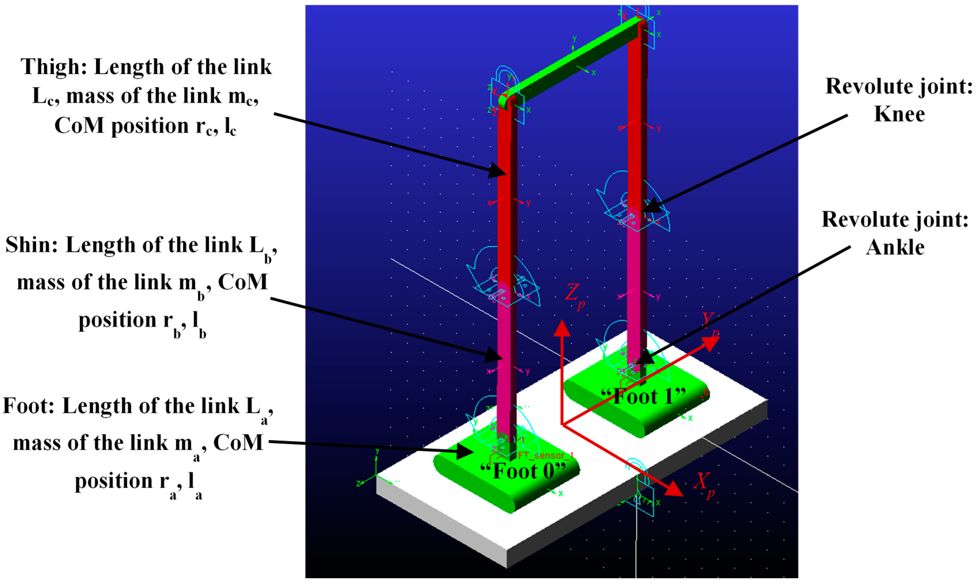
| Link | Weight [kg] | Absolute CoM Position Respect to Xp, Yp, Zp [mm] | Zp [mm] | Relative CoM Position in Xp-Zp Plane [mm] |
|---|---|---|---|---|
| Foot 0 | 6.72 | 0, −200, 26.32 | La = 100 | la = 26.32, ra = 0 |
| Shin 0 | 0.95 | 0, −200, 300 | Lb = 400 | lb = 200; rb = 0 |
| Thigh 0 | 1.16 | 0, −200, 750 | Lc = 500 | lc = 250; rc = 0 |
| Foot 1 | 6.72 | 0, 200, 26.32 | La = 100 | la = 26.32, ra = 0 |
| Shin 1 | 0.95 | 0, 200, 300 | Lb = 400 | lb = 200; rb = 0 |
| Thigh 1 | 1.16 | 0, 200, 750 | Lc = 500 | lc = 250; rc = 0 |
| Waist | 0.94 | 0, 0, 1000 | / | / |
© 2017 by the authors. Licensee MDPI, Basel, Switzerland. This article is an open access article distributed under the terms and conditions of the Creative Commons Attribution (CC BY) license (http://creativecommons.org/licenses/by/4.0/).
Share and Cite
Muscolo, G.G.; Caldwell, D.; Cannella, F. Calculation of the Center of Mass Position of Each Link of Multibody Biped Robots. Appl. Sci. 2017, 7, 724. https://doi.org/10.3390/app7070724
Muscolo GG, Caldwell D, Cannella F. Calculation of the Center of Mass Position of Each Link of Multibody Biped Robots. Applied Sciences. 2017; 7(7):724. https://doi.org/10.3390/app7070724
Chicago/Turabian StyleMuscolo, Giovanni Gerardo, Darwin Caldwell, and Ferdinando Cannella. 2017. "Calculation of the Center of Mass Position of Each Link of Multibody Biped Robots" Applied Sciences 7, no. 7: 724. https://doi.org/10.3390/app7070724
APA StyleMuscolo, G. G., Caldwell, D., & Cannella, F. (2017). Calculation of the Center of Mass Position of Each Link of Multibody Biped Robots. Applied Sciences, 7(7), 724. https://doi.org/10.3390/app7070724