
Thermal Optimization of Horizontal Tubes with Tilted Rectangular Fins under Free Convection for the Cooling of Electronic Devices

Abstract
:1. Introduction
2. Experimental Investigation
3. Results and Discussion
4. Conclusions
Appendix A. Uncertainty Analysis
Acknowledgments
Author Contributions
Conflicts of Interest
References
- Cengel, Y.A. Heat Transfer, 2nd ed.; McGraw-Hill: New York, NY, USA, 2003. [Google Scholar]
- Oktay, S.; Hannemann, R.J.; Bar-Cohen, A. High Heat from a Small Package. Mech. Eng. 1986, 108, 36–42. [Google Scholar]
- Bar-Cohen, A. Thermal Management of Electric Components with Dielectric Liquids. JSME Int. J. Ser. B Fluids Therm. Eng. 1993, 36, 1–25. [Google Scholar] [CrossRef]
- E Pop, Energy Dissipation and Transport in Nanoscale Devices. Nano Res. 2010, 3, 147–169.
- Lasance, C.J.M.; Poppe, A. (Eds.) Thermal Management for LED Applications; Springer: New York, NY, USA, 2014. [Google Scholar]
- Chang, M.-H.; Das, D.; Varde, P.V.; Pecht, M. Light Emitting Diodes Reliability Review. Microelectron. Reliab. 2012, 52, 762–782. [Google Scholar] [CrossRef]
- Liu, J.; Tam, W.S.; Wong, H.; Filip, V. Temperature-dependent Light-Emitting Characteristics of InGaN/GaN Diodes. Microelectron. Reliab. 2009, 49, 38–41. [Google Scholar] [CrossRef]
- Park, J.; Shin, M.; Lee, C.C. Measurement of temperature profiles on visible light-emitting diodes by use of a nematic liquid crystal and an infrared laser. Opt. Lett. 2004, 29, 2656–2658. [Google Scholar] [CrossRef] [PubMed]
- Luo, X.; Liu, S. A Microjet Array Cooling System for Thermal Management of High-brightness LEDs. IEEE Trans. Adv. Packag. 2007, 30, 475–484. [Google Scholar] [CrossRef]
- Narendran, N.; Gu, Y. Life of LED-based White Light Sources. J. Disp. Technol. 2005, 1, 167–171. [Google Scholar] [CrossRef]
- Incropera, F.P. Convection Heat Transfer in Electronic Equipment Cooling. J. Heat Transf. 1988, 110, 1097–1111. [Google Scholar] [CrossRef]
- Nakayama, W. Thermal Management of Electronic Equipment: A Review of Technology and Research Topics. Appl. Mech. Rev. 1986, 39, 1847–1868. [Google Scholar] [CrossRef]
- Welling, J.R.; Wooldridge, C.B. Free Convection Heat Transfer Coefficients from Rectangular Vertical Fins. J. Heat Transf. 1965, 87, 439–444. [Google Scholar] [CrossRef]
- Martynenko, O.G.; Khramtsov, P.P. Free-Convective Heat Transfer; Springer: New York, NY, USA, 2005. [Google Scholar]
- Raithby, G.D.; Hollands, K.G.T. Natural convection. In Handbook of Heat Transfer, 3rd ed.; Rohsenow, W.M., Hartnett, J.P., Cho, Y.I., Eds.; McGraw-Hill: New York, NY, USA, 1998. [Google Scholar]
- Shah, R.K.; Sekulić, D.P. Fundamentals of Heat Exchanger Design; John Wiley & Sons: Hoboken, NJ, USA, 2003. [Google Scholar]
- Sparrow, E.M.; Bahrami, P.A. Experiments on Natural Convection Heat Transfer on the Fins of a Finned Horizontal Tube. Int. J. Heat Mass Transf. 1980, 23, 1555–1560. [Google Scholar] [CrossRef]
- Chen, H.-T.; Chou, J.-C. Investigation of Natural-Convection Heat Transfer Coefficient on a Vertical Square Fin of Finned-Tube Heat Exchangers. Int. J. Heat Mass Transf. 2006, 49, 3034–3044. [Google Scholar] [CrossRef]
- Yildiz, Ş.; Yüncü, H. An Experimental Investigation on Performance of Annular Fins on a Horizontal Cylinder in Free Convection Heat Transfer. Heat Mass Transf. 2004, 40, 239–251. [Google Scholar] [CrossRef]
- Hahne, E.; Zhu, D. Natural Convection Heat Transfer on Finned Tubes in Air. Int. J. Heat Mass Transf. 1994, 37, 59–63. [Google Scholar] [CrossRef]
- Yu, S.-H.; Lee, K.-S.; Yook, S.-J. Natural Convection around a Radial Heat Sink. Int. J. Heat Mass Transf. 2010, 53, 2935–2938. [Google Scholar] [CrossRef]
- Yu, S.-H.; Lee, K.-S.; Yook, S.-J. Optimum Design of a Radial Heat Sink under Natural Convection. Int. J. Heat Mass Transf. 2011, 54, 2499–2505. [Google Scholar] [CrossRef]
- An, B.H.; Kim, H.J.; Kim, D.-K. Nusselt Number Correlation for Natural Convection from Vertical Cylinders with Vertically Oriented Plate Fins. Exp. Therm. Fluid Sci. 2012, 41, 59–66. [Google Scholar] [CrossRef]
- Kim, H.J.; An, B.H.; Park, J.; Kim, D.-K. Experimental Study on Natural Convection Heat Transfer from Horizontal Cylinders with Longitudinal Plate Fins. J. Mech. Sci. Technol. 2013, 27, 593–599. [Google Scholar] [CrossRef]
- Takeishi, K.; Oda, Y.; Miyake, Y.; Motoda, Y. Convective Heat Transfer and Pressure Loss in Rectangular Ducts with Inclined Pin-Fin on a Wavy Endwall. J. Eng. Gas Turbines Power 2013, 135, 061902. [Google Scholar] [CrossRef]
- Hagote, R.B.; Dahake, S.K. Study of Natural Convection Heat Transfer on Horizontal, Inclined and Vertical Heated Plate by V-Fin Array. Int. J. Sci. Eng. Res. 2014, 5, 1366–1374. [Google Scholar]
- Lee, J.B.; Kim, H.J.; Kim, D.-K. Experimental Study of Natural Convection Cooling of Vertical Cylinders with Inclined Plate Fins. Energies 2016, 9, 391. [Google Scholar] [CrossRef]
- Churchill, S.W.; Chu, H.H.S. Correlating equations for laminar and turbulent free convection from a horizontal cylinder. Int. J. Heat Mass Transf. 1975, 18, 1049–1053. [Google Scholar] [CrossRef]


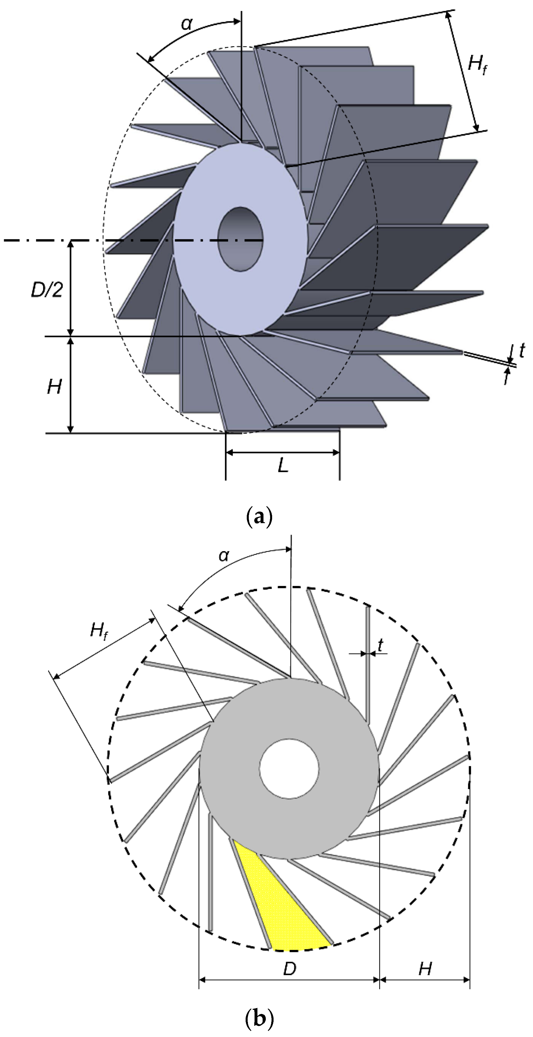
| No. | N | α | L | D | H | t |
|---|---|---|---|---|---|---|
| 1 | 9 | 90° | 50 mm | 60 mm | 30 mm | 1.0 mm |
| 2 | 12 | |||||
| 3 | 18 | |||||
| 4 | 9 | 60° | ||||
| 5 | 12 | |||||
| 6 | 18 | |||||
| 7 | 36 | |||||
| 8 | 9 | 30° | ||||
| 9 | 12 | |||||
| 10 | 18 | |||||
| 11 | 36 |
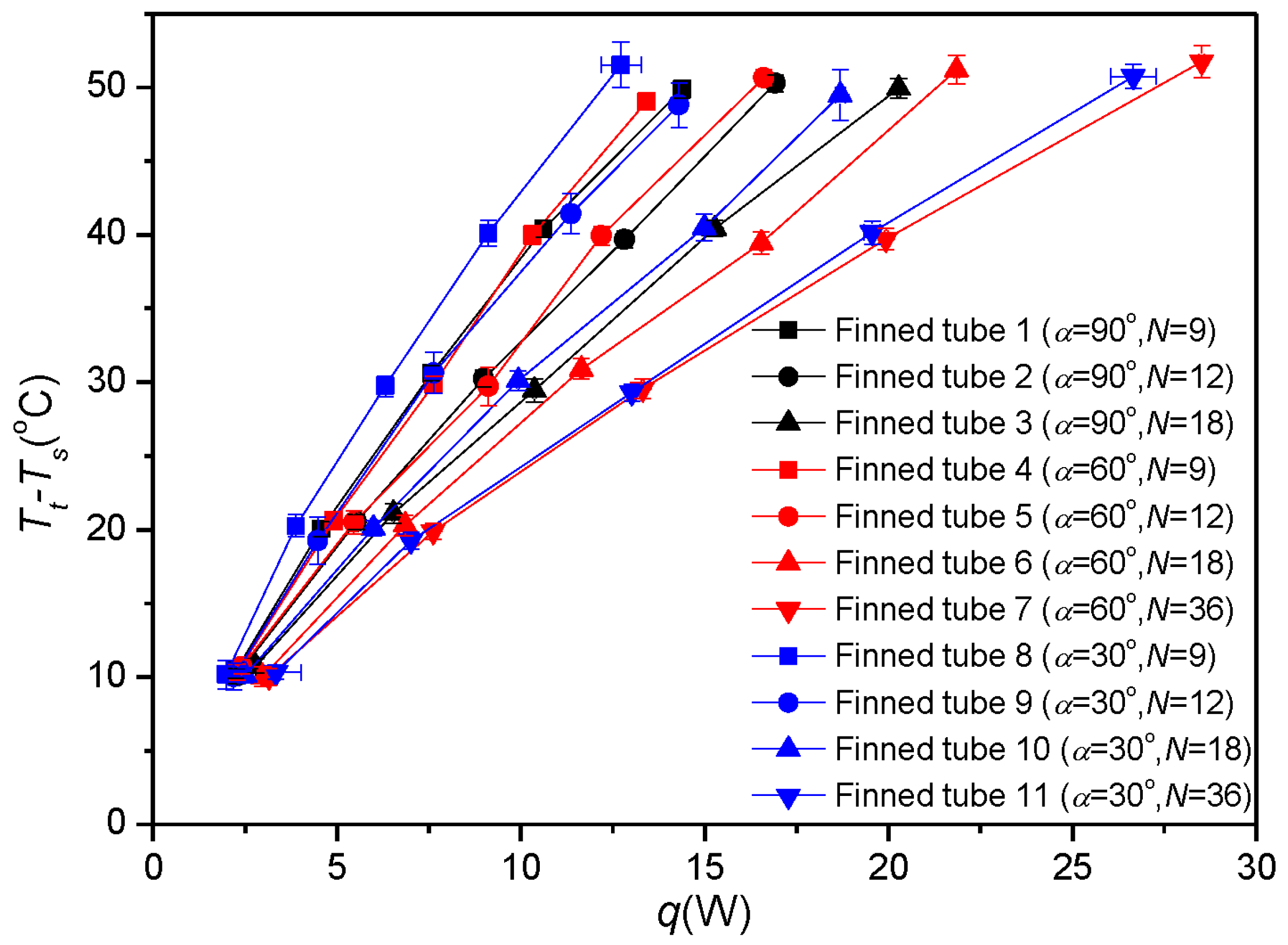
| No. | α | N | Tt − Ts [°C] | q [W] | 1/Rth [W/°C] | NuD |
|---|---|---|---|---|---|---|
| 1 | 90° | 9 | 10.4 ± 0.5 | 2.24 ± 0.01 | 0.216 ± 0.011 | 8.71 ± 0.44 |
| 20 ± 0.5 | 4.58 ± 0.02 | 0.228 ± 0.006 | 9.23 ± 0.25 | |||
| 30.6 ± 0.5 | 7.57 ± 0.01 | 0.247 ± 0.004 | 9.99 ± 0.17 | |||
| 40.4 ± 0.6 | 10.61 ± 0.02 | 0.263 ± 0.004 | 10.61 ± 0.15 | |||
| 49.9 ± 0.6 | 14.39 ± 0.02 | 0.289 ± 0.003 | 11.66 ± 0.14 | |||
| 2 | 90° | 12 | 10.1 ± 0.5 | 2.27 ± 0 | 0.226 ± 0.011 | 7.14 ± 0.36 |
| 20.5 ± 0.5 | 5.53 ± 0.01 | 0.269 ± 0.007 | 8.51 ± 0.22 | |||
| 30.3 ± 0.6 | 8.99 ± 0.02 | 0.297 ± 0.006 | 9.39 ± 0.18 | |||
| 39.7 ± 0.5 | 12.83 ± 0.02 | 0.323 ± 0.004 | 10.22 ± 0.14 | |||
| 50.3 ± 0.6 | 16.91 ± 0.02 | 0.336 ± 0.004 | 10.63 ± 0.12 | |||
| 3 | 90° | 18 | 10.8 ± 0.5 | 2.79 ± 0.01 | 0.26 ± 0.012 | 5.71 ± 0.27 |
| 21.1 ± 0.7 | 6.53 ± 0.04 | 0.309 ± 0.01 | 6.81 ± 0.22 | |||
| 29.5 ± 0.8 | 10.37 ± 0.05 | 0.352 ± 0.01 | 7.75 ± 0.21 | |||
| 40.4 ± 0.5 | 15.28 ± 0.01 | 0.378 ± 0.005 | 8.32 ± 0.11 | |||
| 49.9 ± 0.6 | 20.28 ± 0.03 | 0.406 ± 0.005 | 8.94 ± 0.12 | |||
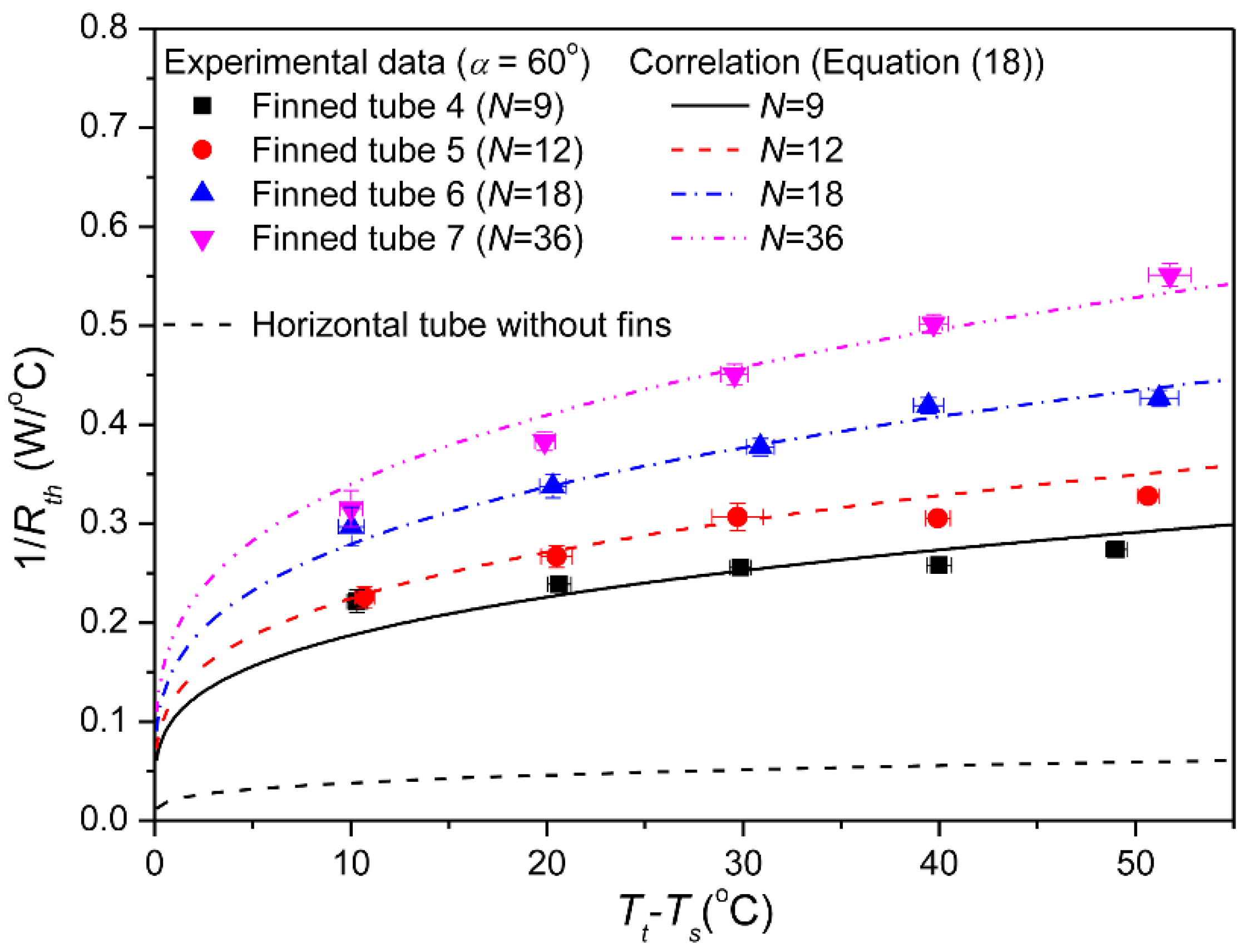
| 4 | 60° | 9 | 10.3 ± 0.5 | 2.29 ± 0.02 | 0.221 ± 0.011 | 11.28 ± 0.59 |
| 20.6 ± 0.6 | 4.92 ± 0.03 | 0.239 ± 0.007 | 12.16 ± 0.36 | |||
| 29.9 ± 0.5 | 7.63 ± 0.02 | 0.255 ± 0.005 | 13.01 ± 0.24 | |||
| 40 ± 0.6 | 10.31 ± 0.03 | 0.258 ± 0.004 | 13.14 ± 0.21 | |||
| 49 ± 0.5 | 13.42 ± 0.02 | 0.274 ± 0.003 | 13.95 ± 0.15 | |||
| 5 | 60° | 12 | 10.7 ± 0.5 | 2.42 ± 0 | 0.226 ± 0.011 | 9.11 ± 0.43 |
| 20.5 ± 0.8 | 5.47 ± 0.05 | 0.267 ± 0.011 | 10.74 ± 0.44 | |||
| 29.7 ± 1.3 | 9.11 ± 0.1 | 0.306 ± 0.014 | 12.35 ± 0.56 | |||
| 39.9 ± 0.6 | 12.19 ± 0.03 | 0.305 ± 0.005 | 12.3 ± 0.2 | |||
| 50.6 ± 0.5 | 16.61 ± 0.02 | 0.328 ± 0.004 | 13.21 ± 0.14 | |||
| 6 | 60° | 18 | 10 ± 0.7 | 2.98 ± 0.04 | 0.297 ± 0.02 | 8.44 ± 0.56 |
| 20.3 ± 0.7 | 6.86 ± 0.04 | 0.338 ± 0.012 | 9.6 ± 0.33 | |||
| 30.9 ± 0.7 | 11.66 ± 0.04 | 0.377 ± 0.009 | 10.73 ± 0.24 | |||
| 39.4 ± 0.7 | 16.54 ± 0.05 | 0.419 ± 0.008 | 11.92 ± 0.23 | |||
| 51.2 ± 1 | 21.85 ± 0.07 | 0.427 ± 0.008 | 12.13 ± 0.23 | |||
| 7 | 60° | 36 | 10 ± 0.6 | 3.16 ± 0.02 | 0.315 ± 0.018 | 4.76 ± 0.28 |
| 19.9 ± 0.5 | 7.62 ± 0.01 | 0.383 ± 0.01 | 5.78 ± 0.15 | |||
| 29.6 ± 0.7 | 13.32 ± 0.04 | 0.451 ± 0.01 | 6.8 ± 0.16 | |||
| 39.7 ± 0.7 | 19.93 ± 0.05 | 0.502 ± 0.009 | 7.57 ± 0.14 | |||
| 51.7 ± 1.1 | 28.51 ± 0.08 | 0.551 ± 0.011 | 8.31 ± 0.17 | |||
| 8 | 30° | 9 | 10.2 ± 1 | 1.99 ± 0.07 | 0.195 ± 0.02 | 11.55 ± 1.17 |
| 20.2 ± 0.8 | 3.89 ± 0.03 | 0.192 ± 0.007 | 11.4 ± 0.44 | |||
| 29.7 ± 0.7 | 6.31 ± 0.13 | 0.212 ± 0.007 | 12.59 ± 0.39 | |||
| 40.1 ± 0.9 | 9.12 ± 0.2 | 0.227 ± 0.007 | 13.49 ± 0.42 | |||
| 51.5 ± 1.6 | 12.72 ± 0.55 | 0.247 ± 0.013 | 14.65 ± 0.77 | |||
| 9 | 30° | 12 | 10 ± 0.9 | 2.19 ± 0.06 | 0.219 ± 0.021 | 10.36 ± 0.99 |
| 19.2 ± 1.6 | 4.48 ± 0.13 | 0.233 ± 0.021 | 11.02 ± 0.97 | |||
| 30.6 ± 1.4 | 7.64 ± 0.11 | 0.249 ± 0.012 | 11.81 ± 0.56 | |||
| 41.4 ± 1.4 | 11.37 ± 0.11 | 0.274 ± 0.009 | 12.99 ± 0.45 | |||
| 48.8 ± 1.5 | 14.3 ± 0.12 | 0.293 ± 0.009 | 13.88 ± 0.44 | |||
| 10 | 30° | 18 | 10.1 ± 0.5 | 2.51 ± 0.01 | 0.248 ± 0.012 | 8.35 ± 0.42 |
| 20.1 ± 0.5 | 5.99 ± 0.01 | 0.298 ± 0.008 | 10.05 ± 0.26 | |||
| 30.1 ± 0.7 | 9.93 ± 0.04 | 0.33 ± 0.007 | 11.12 ± 0.25 | |||
| 40.5 ± 0.9 | 14.99 ± 0.07 | 0.37 ± 0.009 | 12.49 ± 0.29 | |||
| 49.5 ± 1.7 | 18.69 ± 0.14 | 0.378 ± 0.013 | 12.75 ± 0.45 | |||
| 11 | 30° | 36 | 10.3 ± 0.5 | 3.34 ± 0.67 | 0.324 ± 0.067 | 5.87 ± 1.22 |
| 19.2 ± 0.6 | 7.01 ± 0.05 | 0.364 ± 0.011 | 6.6 ± 0.2 | |||
| 29.3 ± 0.6 | 13.02 ± 0.11 | 0.444 ± 0.01 | 8.05 ± 0.17 | |||
| 40.2 ± 0.8 | 19.55 ± 0.22 | 0.487 ± 0.011 | 8.82 ± 0.2 | |||
| 50.8 ± 0.8 | 26.65 ± 0.62 | 0.525 ± 0.015 | 9.52 ± 0.27 |
| Constraints | Properties | ||
|---|---|---|---|
| Tt−Ts | 50 °C | αf | 2.23 × 10⁻⁵ m2/s |
| L | 50 mm | βf | 0.0033/K |
| D | 60 mm | νf | 1.6 × 10⁻⁵ m2/s |
| H | 30 mm | kf | 0.026 W/m·K |
| N | 9–36 | ks | 220 W/m·K |
| α | 60° | - | - |
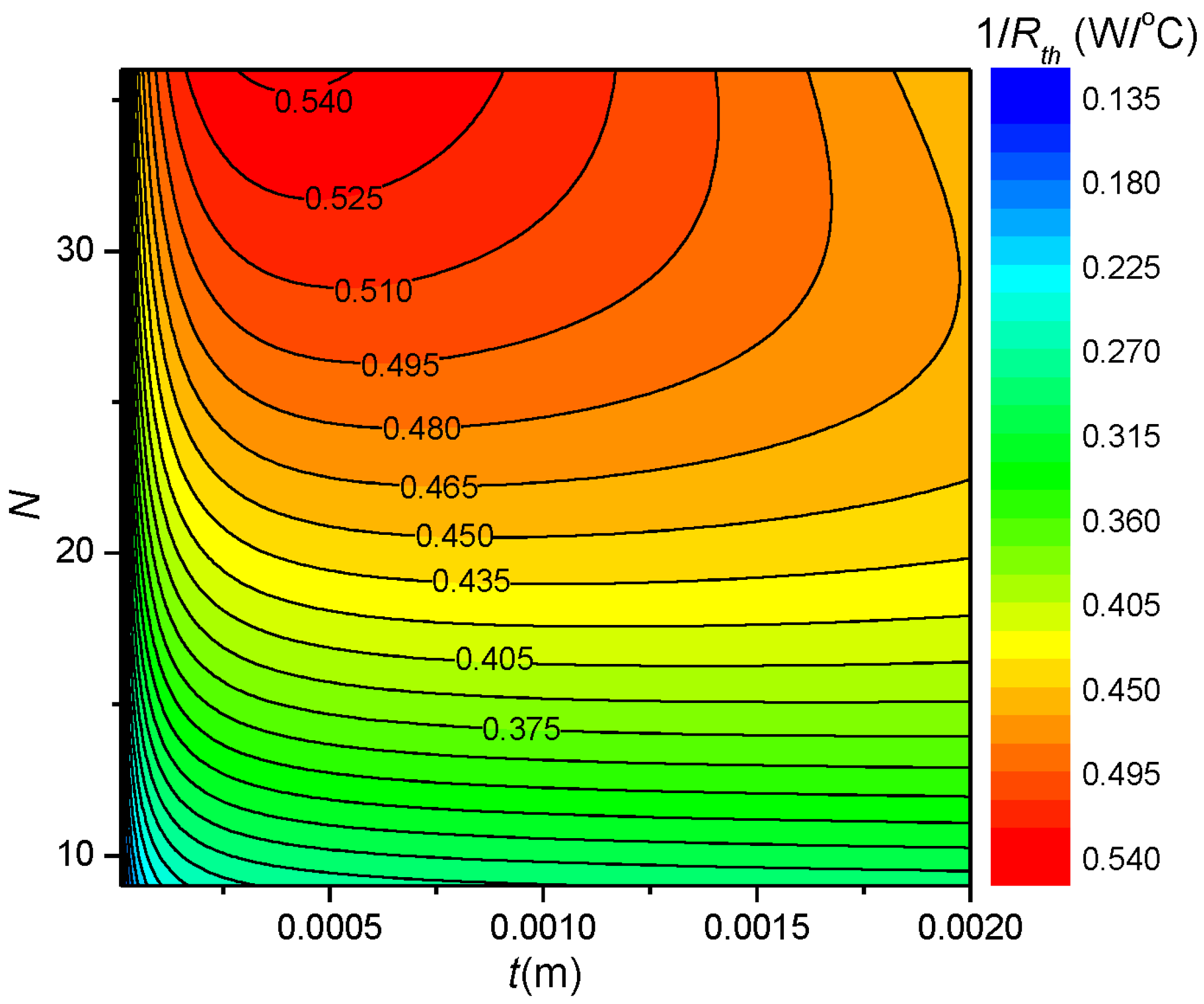
| Configuration | N | t [mm] | 1/Rth [W/K] |
|---|---|---|---|
| Horizontal | 36 | 0.4 | 0.543 |
| Vertical [27] | 36 | 0.62 | 0.943 |
© 2017 by the authors. Licensee MDPI, Basel, Switzerland. This article is an open access article distributed under the terms and conditions of the Creative Commons Attribution (CC BY) license (http://creativecommons.org/licenses/by/4.0/).
Share and Cite
Lee, J.B.; Kim, H.J.; Kim, D.-K. Thermal Optimization of Horizontal Tubes with Tilted Rectangular Fins under Free Convection for the Cooling of Electronic Devices. Appl. Sci. 2017, 7, 352. https://doi.org/10.3390/app7040352
Lee JB, Kim HJ, Kim D-K. Thermal Optimization of Horizontal Tubes with Tilted Rectangular Fins under Free Convection for the Cooling of Electronic Devices. Applied Sciences. 2017; 7(4):352. https://doi.org/10.3390/app7040352
Chicago/Turabian StyleLee, Jong Bum, Hyun Jung Kim, and Dong-Kwon Kim. 2017. "Thermal Optimization of Horizontal Tubes with Tilted Rectangular Fins under Free Convection for the Cooling of Electronic Devices" Applied Sciences 7, no. 4: 352. https://doi.org/10.3390/app7040352
APA StyleLee, J. B., Kim, H. J., & Kim, D.-K. (2017). Thermal Optimization of Horizontal Tubes with Tilted Rectangular Fins under Free Convection for the Cooling of Electronic Devices. Applied Sciences, 7(4), 352. https://doi.org/10.3390/app7040352