Article

Simulation of Permanent Deformation in High-Modulus Asphalt Pavement with Sloped and Horizontally Curved Alignment

1
Key Laboratory for Special Area Highway Engineering of Ministry of Education, Chang’an University, Xi’an 710064, China
2
First Highway Consultants Co., Ltd., Xi’an 710075, China
3
China Railway First Survey & Design Institute Group Co., Ltd., Xi’an 710054, China
4
Highway Administration Bureau of Transportation Department, Jinan 250002, China
5
Shandong College of Highway Technician, Jinan 250002, China
*
Author to whom correspondence should be addressed.
Appl. Sci. 2017, 7(4), 331; https://doi.org/10.3390/app7040331
Submission received: 30 December 2016 / Revised: 20 March 2017 / Accepted: 24 March 2017 / Published: 28 March 2017
(This article belongs to the Special Issue Advanced Asphalt Materials and Paving Technologies)

Abstract

:
This study aims to evaluate the permanent deformation of high-modulus asphalt pavement in special road using viscoelastic theory. Based on the creep test, the Prony series representation of Burgers model parameters for different asphalt mixtures were obtained and used in the deformation simulation of a high-modulus asphalt pavement situated in a horizontally curved ramp. The orthogonal design method was used to show the effect of different factors on the deformation. Results reveal that rutting in curved ramp was greater than in straightaway. Further, evident upheaval was found on the downhill pavement surface and outer pavement parts of the curve due to longitudinal friction force and sideway force. In addition, the upper and middle asphalt courses in such road seemed more crucial to pavement anti-rutting performance, since inclusion of shear force changed pavement deformation characteristic and the potential rutting area tended to move up. Finally, a preliminary equation to predict rutting in sloped and curved road with widely accepted pavement structure in China was proposed.

1. Introduction

Rutting, thermal cracking and fatigue cracking have long been regarded as serious issues confronting asphalt pavement due to increasing aggressiveness posed by huge traffic volume, heavy axle load and severe climate conditions [1]. It is widely accepted that asphalt mixture could be considered to be a viscoelastic material because its deformation relates closely to stress, time as well as temperature. Therefore, inclusion of viscoelastic theory in the permanent deformation investigation is a common practice [2,3,4,5,6].
With the development of computing technique and the publishing of a variety of commercial finite element software, modeling permanent deformation using experimentation-based viscoelastic mechanics has been preferred by many researchers [7,8,9]. However, their studies focused mainly on rutting in simple road, i.e., straightaways. Actually, it was found that rutting in special roads such as long steep uphill road, sharp horizontal curve, intersections, etc., were more serious, since pavement stress in these cases seems more intricate and vehicle speed is considerably reduced [10,11]. A case in point is that many asphalt pavements near signalized intersections in southern Nevada experienced severe rutting, according to historical documents [12]. Moreover, other investigations also verified the severity of rutting in special roads. For instance, Yang presented a full-thickness rutting test to evaluate rutting performance of asphalt pavement in continuous uphill section [13]. Yang et al. modeled the shear stress and vertical strain of asphalt pavement located in long steep longitudinal ramp and found that rutting in such condition was more susceptible to axle load [14]. Li et al. inspected the rutting depth of four signalized intersections in Nanjing, China and found that the deformations caused by tangential and vertical forces were more serious and their sensitivity to traffic and loading time was greatly enhanced [15]. Up to now, although some research was carried out on modeling rutting by considering both vertical and shearing load, models in these studies simply incorporated shear force caused by longitudinal slope, whereas the centrifugal action in curves was usually neglected. In addition, nowadays researchers have developed multiple materials to relieve rutting [16]. Among them, high-modulus asphalt concrete (HMAC), first developed in France, is a kind of hot asphalt mixture whose dynamic modulus (15 °C, 10 Hz) is greater than 14,000 MPa, and hence is more resistant to rutting than traditional asphalt mixture. To achieve huge mixture modulus several measures are frequently adopted, which involve introducing a special additive, using hard-grade bitumen and developing better aggregate blend, etc. Although some studies on the permanent deformation of this new material were reported [17,18], this new material in rutting modeling is rarely considered.
In response, this research simulated the permanent deformation of a HMAC pavement in a sloped and horizontally curved road by using the viscoelastic finite element method. The uniaxial static creep test was firstly performed to obtain the Burgers model parameters, which were subsequently used in the modeling. Meanwhile, adaptability of the Burgers model to the simulation was verified by simulating the creep test with ANSYS (ANSYS 2010, NASDAQ: ANSS, Canonsburg, PA, USA, 1970). Afterwards, deformation of the pavement was modeled and the effects of several factors on the deformation were analyzed based on the orthogonal design method. Particularly, a comparison between the deformations in straightaway and in sloped and curved road was made. Finally, a rutting prediction equation for HMAC pavement with sloped and curved alignment was proposed.

2. Materials and Methods

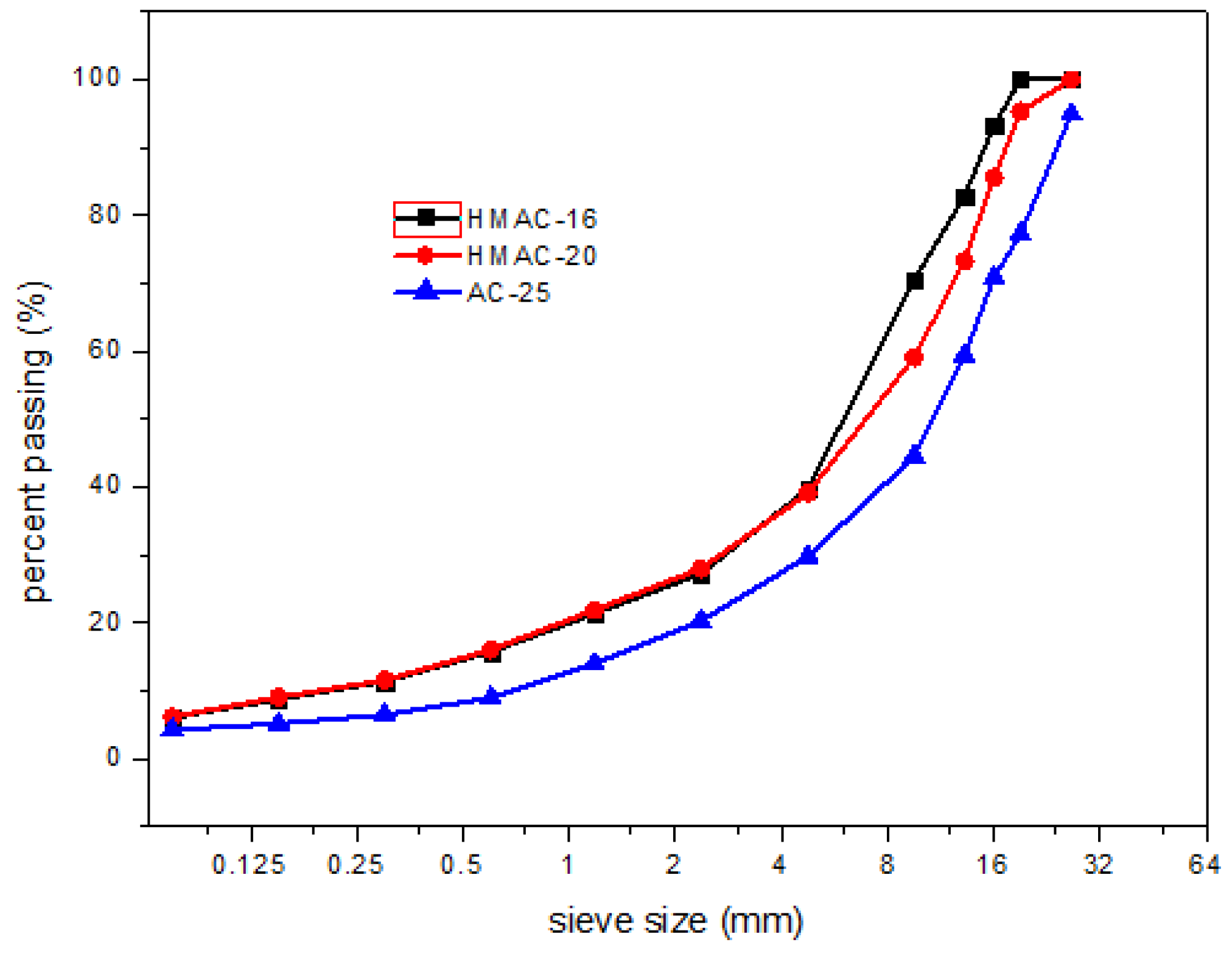
2.1. Binder and Aggregates

The widely-used A-70 bitumen [19] in China was employed as the asphalt binder, which has a 25 °C penetration from 60 to 80 (0.1 mm), and a ring and ball softening point greater than 45 °C.
Two optimized gradations were used to fabricate HMACs in this research. They were developed by the authors in preliminary studies [20], which are denoted by HMAC-16 and HMAC-20 (HMAC is short for high-modulus asphalt concrete, 16/20 is nominal maximum particle size). These gradations were experiment-based gradations in which the final gradation was selected by preparing asphalt mixture samples and conducting a series of performance tests such as the Marshall stability test, rutting test, low temperature mixture bending test and shearing test. Aside from these two gradations, the commonly adopted dense gradation AC-25 (AC is short for asphalt concrete) was also included for comparison. The three gradations are shown in Figure 1.

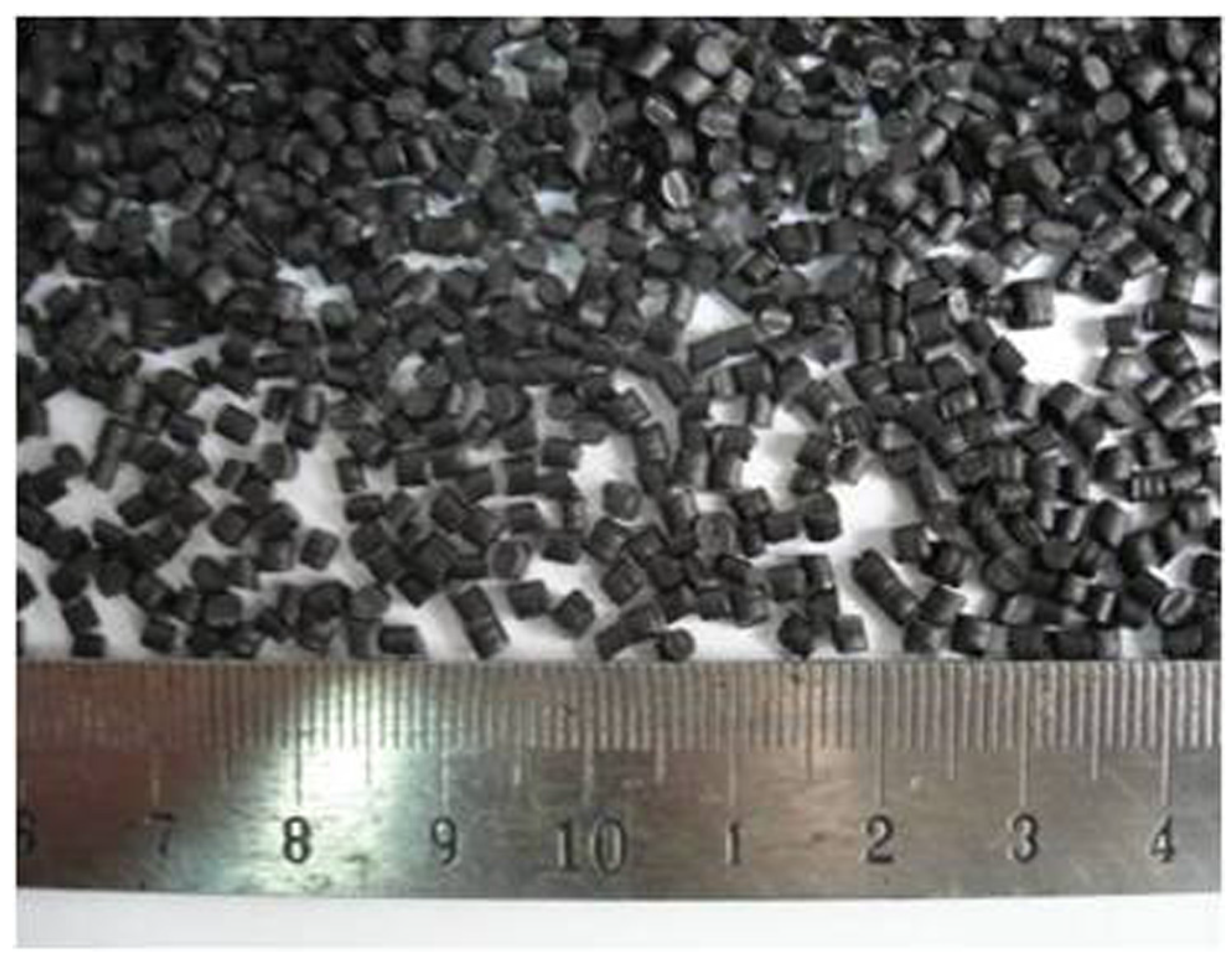
2.2. High-Modulus Additive
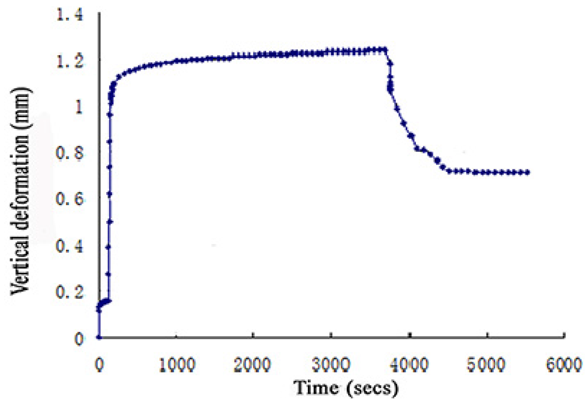
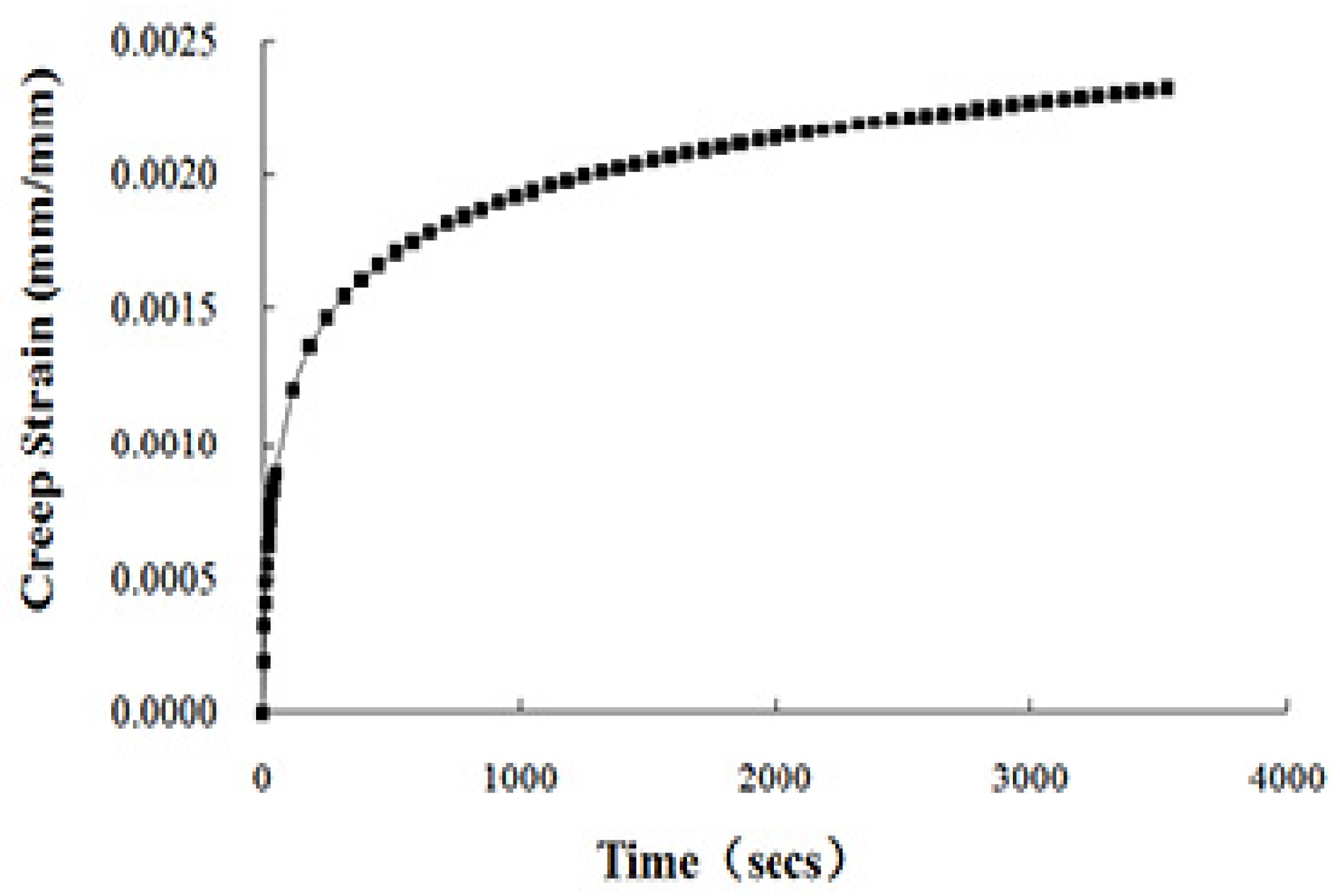
The high-modulus additive used is a blend of 4 mm dark blue or black cylindrical granules developed by PR INDUSTRIE, Paris, France (shown in Figure 2), whose main component is modified high-density polyethylene [20]. The high modulus additive content was determined as 0.4% by weight of whole asphalt mixture. It should be blended first with hot aggregates for 15 s and then mixed with hot asphalt and mineral filler to ensure uniform dispersion in the mixture.

2.3. Creep Test

As it can be easily manipulated, the uniaxial static creep test is frequently preferred for asphalt mixture out of available test alternatives [21,22]. In this study, the creep test was performed on a group of Φ100 mm × 100 mm statically compacted cylindrical specimens using the MTS 810 system. The testing temperature was selected as 50 °C since rutting frequently occurs in the moderate to high temperature domain. For each mixture, three repetitions were undertaken to reduce experimental error. Before loading, all samples were kept in an oven for 4 h at 50 °C to reduce temperature deviation. In addition, before testing, a small amount of plaster was used on the sample top for leveling and the teflon sheets were placed between specimen end and the loading platen to reduce cyclo-hoop effect.
The loading protocol is: at the beginning of the loading, a 0.003 MPa stress lasting for 120 s was applied to maintain a positive contact between specimen and platen. Then, a 0.3 MPa stress lasting for 3600 s was applied to induce creep deformation. After that, the sample is unloaded for a rest period of 1800 s. During the whole process, the stress and strain were recorded automatically to develop viscoelastic parameter.

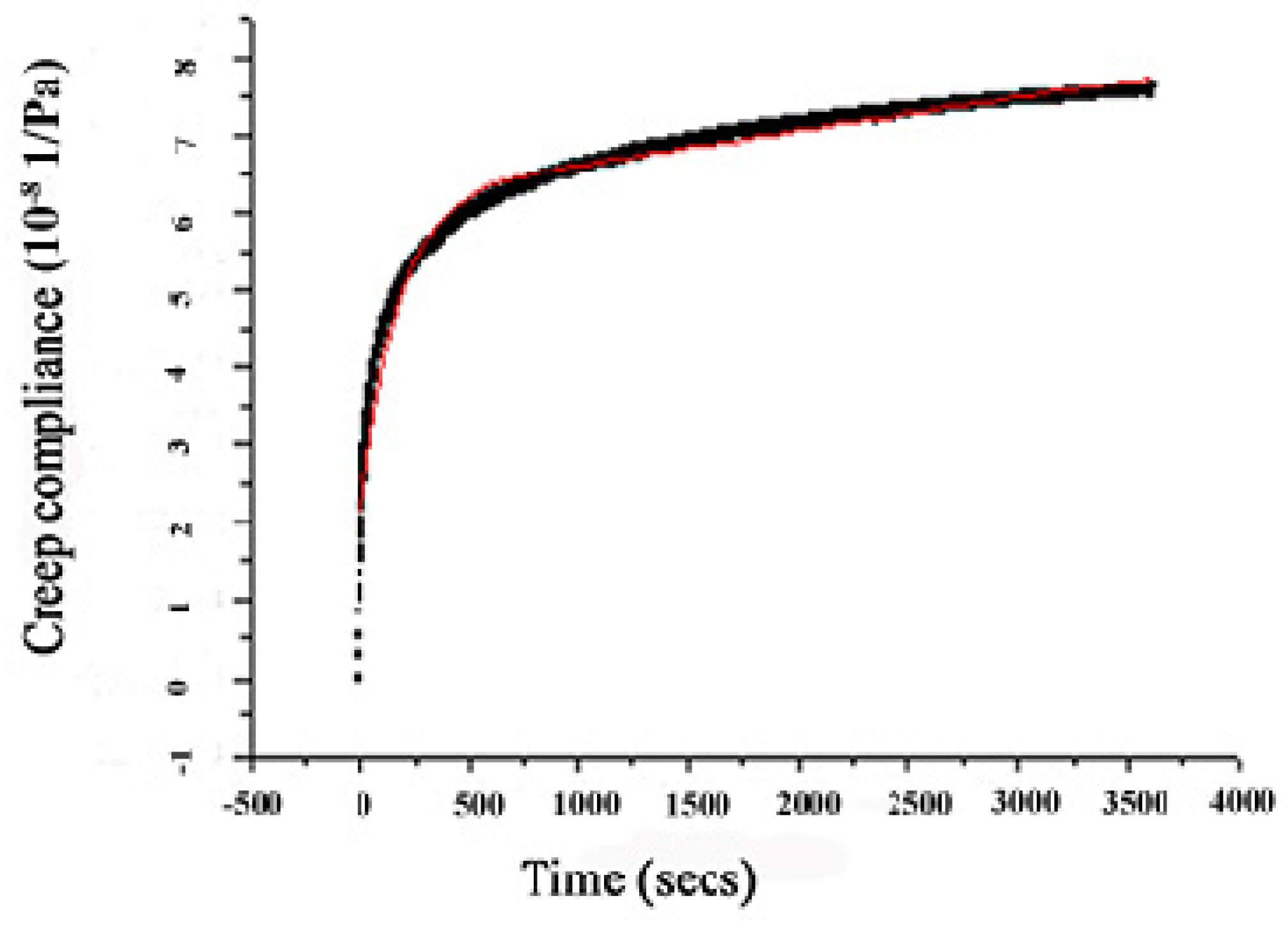
2.4. Viscoelastic Model and Its Adaptability

Since the linear viscoelastic theory has been widely applied in permanent deformation analysis of asphalt pavement [6,21], this research selected the Burgers model in the simulation, which was found effective in reflecting the instantaneous and lagged elastic strain as well as the viscous flow of asphalt mixture [22]. Its constitutive equation is expressed as follows.
ε ( t ) = σ 0 [ t η 1 + 1 E 1 + 1 E 2 ( 1 e t E 2 η 2 ) ]
where σ 0 is the original stress; ε ( t ) is the creep strain at time t; and E1, E2, η1 and η2 are the model coefficients which could be obtained by regression on the creep data.
According to the creep test, the total deformation–time curve of the specimen was obtained automatically, as is shown in Figure 3. Based on this curve, the total strain–time curve could be obtained by dividing the deformation by specimen height. However, after subtracting the elastic strain from the total strain, the creep strain–time curve during the constant 3600 s loading period was developed as shown in Figure 4. Finally, the parameters of Burgers model (E1, η1, E2 and η2) for various mixtures could be acquired by conducting multivariate regression on creep data.
In ANSYS, the creep model for a linear viscoelastic solid are not represented in Equation (1) but instead in the Prony series representation shown in Equation (2), because the Prony series uses a series of decaying exponentials to reach remarkable computational efficiency and explicit physical basis [23].
G ( t ) = G 1 [ g 1 e t τ 1 + g 2 e t τ 2 ]
where G ( t ) is the shearing modulus at time t, G 1 is the initial shearing modulus; g1, g2, τ1 and τ2 are the Prony representation coefficients.
Since the Burgers model parameters have some connection with the Prony coefficients, these four parameters can be converted into the Prony representation coefficients (g1, g2, τ1, τ2), according to the method in the literature [24]. The fitted Burgers model parameters at 50 °C and the corresponding converted Prony series coefficients for different asphalt mixtures are shown in Table 1.
To ensure the included model could characterize the deformation of HMAC adequately, verification of the model adaptability was conducted by modeling the creep test numerically and by comparing the simulation with the test results.
Since the creep test took the Φ100 mm cylinder, which was 100 mm high as the specimen, a three-dimensional model was constructed accordingly in the verification analysis. For the boundary condition the degree of freedom (DOFs) along the Z-axis on the model bottom was zero and the model was horizontally unconfined. The same loading program to the aforementioned creep test was employed in the simulating.
The creep compliance–time curves obtained from both the numerical simulation and the creep test are given in Figure 5. From this figure, a good fitness between them with a relative error no more than 3.2% was observed, indicating that the Burgers model is feasible in evaluating the permanent deformation of HMAC.

3. Simulating HMAC Pavement Deformation in Curved Ramp

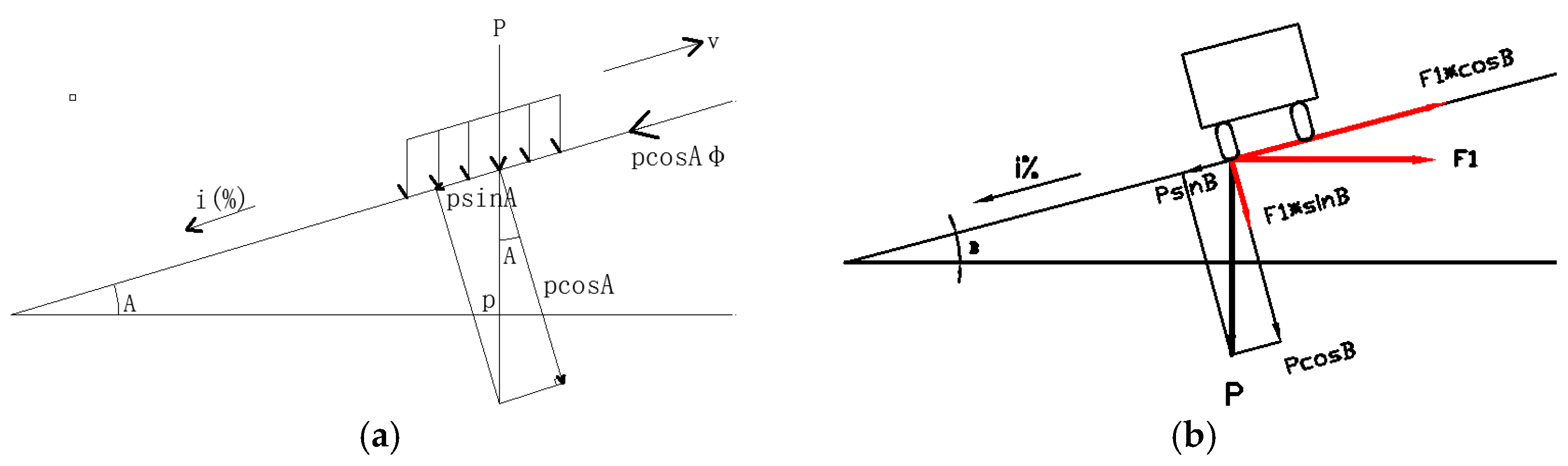
3.1. Road Alignment Feature

Field investigation revealed that rutting in special road was more serious than in straight and flat highways [25]. However, the terminology ‘special road’ includes profound implications. This section here presents four frequently encountered special roads and their geometric features as well as pavement stress characteristics. Moreover, the most unfavorable condition among them was selected for the following modeling.
Typical special roads involve: First, a flat straight way with dramatic speed change, which usually appears near a tollgate or an intersection. In this case, asphalt pavement is subjected to a shear force resulting from acceleration. The second is consecutive steep route in which the shear force applied to pavement mainly originates from the gravity component along the gradient. Speed change will also contribute to the shear force to which the pavement is subjected. The third is a horizontally curved alignment. Due to the centrifugal force, a force departing from the curvature centre is imposed on the pavement. This is called the sideway force, which increases with the decrease of radius. The last special road is the horizontally curved and sloped highway, which is the combination of the second and third condition. In this case, the forces imposed onto the pavement are rather complicated due to dual action of centrifugal force and longitudinal friction. The fourth condition had been proven to be the most unfavorable by the authors of [25], so it was employed to represent special road in the following model.
In curved ramp, the pavement unit bears two different shear forces, which are stemmed from the transverse and longitudinal friction between vehicle wheels and pavement surface as shown in Figure 6. One of them, the longitudinal friction force fl should offset the component of wheel pressure p along the slope as well as the rolling friction force, according to Figure 6a. Based on the design speed and maximum gradient for roads at different levels in the Highway Alignment Design Specification [26], the longitudinal friction force fl could be calculated as depicted in Table 2. The calculation shows that the longitudinal friction force was almost 0.6 of the standard 0.707 MPa vertical tire pressure at a profile of 5%.
Similarly, the transverse friction force ft could also be determined by multiplying tire pressure by a factor that reflects the effect of radius. The factor is called sideway force coefficient (SFC). According to the Highway Alignment Design Specification, this analysis took the largest SFC of 0.2 for considering the worst condition [26].

3.2. ANSYS Model

The three-dimensional pavement model with dimensions in the longitudinal, transverse and depth direction of 2.1, 2.0 and 7.55 m respectively was constructed. This pavement unit is assumed to be located near the midpoint of the horizontal curve. The pavement structure and the thickness of each layer are shown in Table 3.
Based on the multi-layered pavement system, two different hypotheses—i.e., the elastic and linear viscoelastic hypotheses—were introduced for various layers. The former applied to semi-rigid base, subbase and subgrade which used the Solid 45 element for analyzing, while the viscoelastic hypothesis was applied to asphaltic layers which employed the 8-node Solid 185 element in the computation. Moreover, the Surf 154 element was adopted to simulate the shear force on pavement surface. For the asphaltic layers, the aforementioned viscoelastic parameters (shown in Table 1) were employed, while for the other layers, the elastic parameters are provided in Table 3.
Consideration of different constitutive relationships for different layers in this research can be justified as follows. In China today, asphalt pavement composed of asphaltic surface course as well as semi-rigid base and subbase is the overwhelmingly adopted structure. Numerous in-situ investigations indicate that during hot days, rutting deformation in such pavement mainly derives from viscous flow of asphaltic mixtures, whereas the contribution of semi-rigid base, subbase and subgrade is relatively small, provided that the pavement was well designed and constructed. Therefore, to highlight the deformation of asphaltic layers and to raise computation efficiency, this research applied viscoelastic theory to asphaltic layers while using elastic theory for the others.
The vertical load is the uni-axle-two-wheel load, which has a rectangular uniform pattern and a dual tire spacing of 31.95 cm. The wheel contact area is 20 cm long and 20 cm wide. Based on previous analysis, two shear forces (longitudinal and transverse force) were applied to the model top, which were determined through multiplying the vertical pressure by 0.6 and 0.2 respectively. In terms of loading time, since similar rutting predicting results under repeated loading–unloading cycles and single long time loading have been verified [27], in this study numerous individual loading was approximately accumulated into single long time load according to the Boltzmann Superposition principle. In this modeling, the equivalent single axle load (ESAL) number ranging from 200 to 2800 (104 times) and an operational velocity of 100 km/h were considered. The corresponding accumulated loading times were calculated as shown in Table 4. Additionally, the lateral wander factor of 0.4 was adopted in the calculation in accordance with current code [26]. Since the pavement deformation at the moment of unloading includes both elastic deformation and non-elastic, different recovering times were considered as shown in Table 4.

4. Results and Discussion

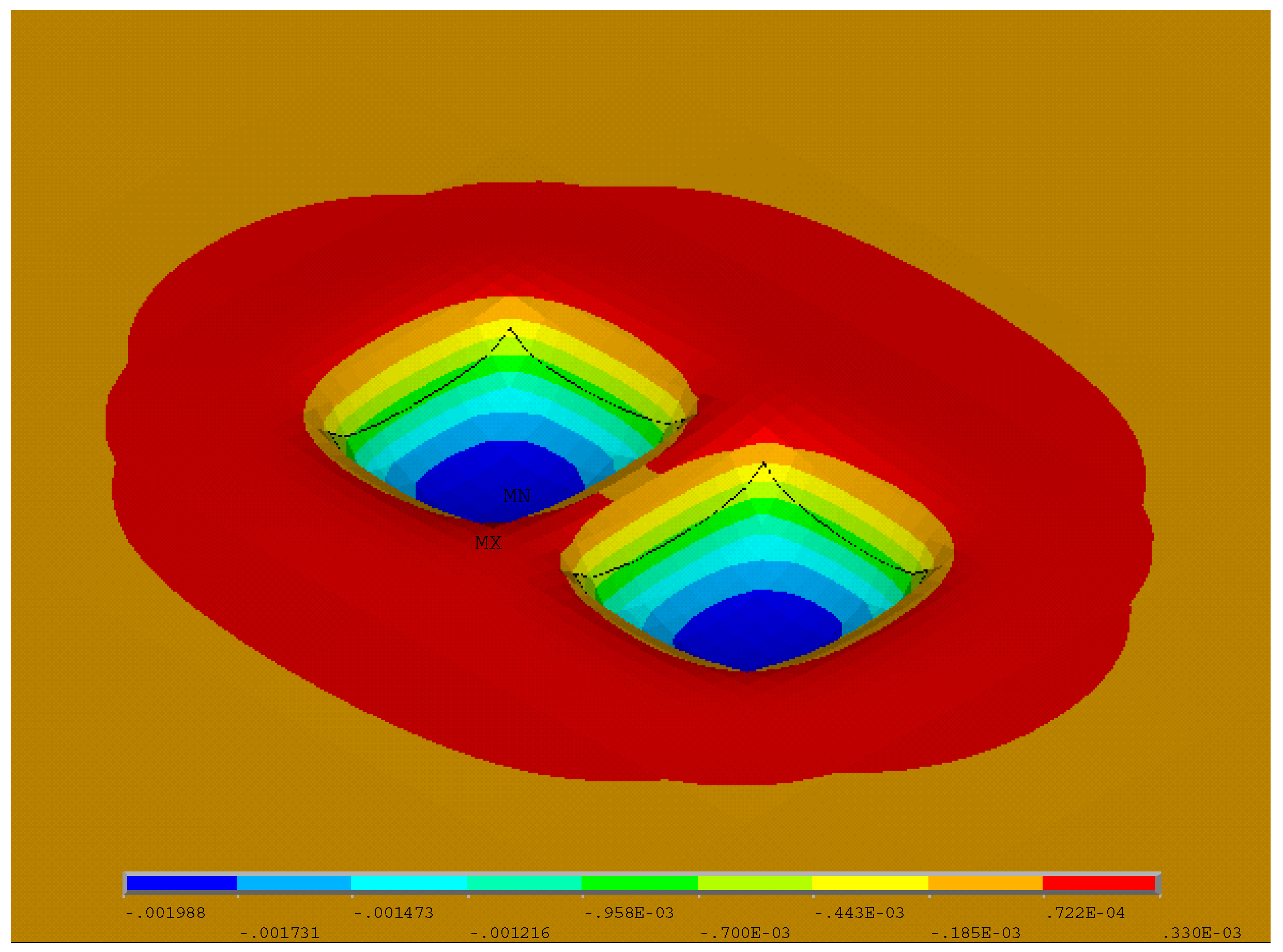
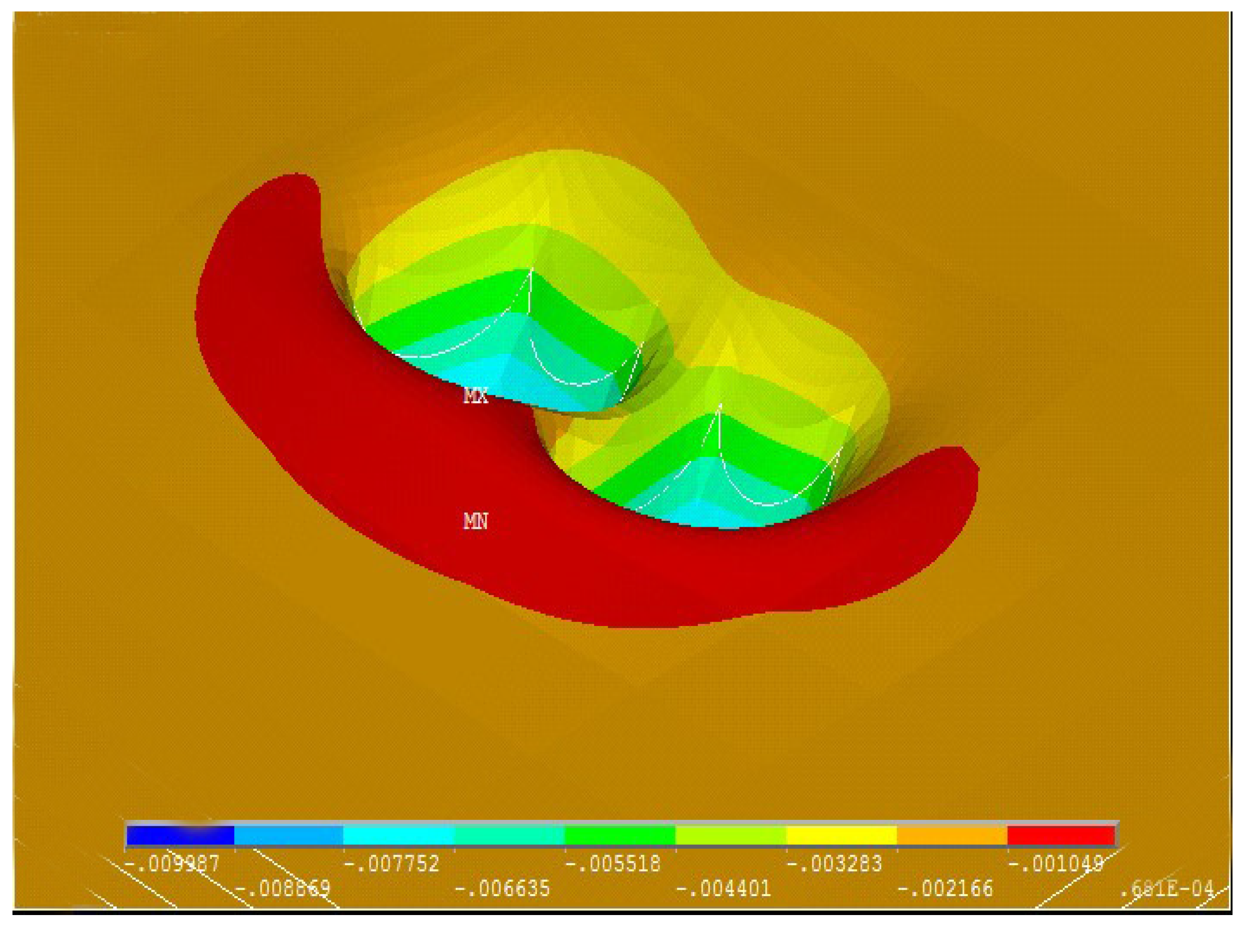
4.1. Contrast of Permanent Deformation in Flat Straight Road and Curved Ramp

As illustrated in nephograms, the permanent deformations in straight and flat road as well as those in the horizontally curved and sloped section are shown in Figure 7 and Figure 8 respectively.
It was found that asphaltic mixtures in the pavement surface courses under two different alignments showed slow viscous flow after prolonged loading and unloading cycles, and different locations featured quite different deformations. Overall, the deformation decreased with the distance from axle center increasing. It was observed that the greatest vertical displacement occurred right below the axle load since the vertical compressive stress herein reaches the maximum value. In contrast, asphaltic mixture that is around the wheel contact area showed swelling due to considerable lateral extruding force.
However, the deformation in curved ramp showed some differences in terms of magnitude and deformation features. On the one hand, it is seen from the above two figures that the compressive deformation in curved and sloped roadway was greater than in the simple straight highway. Detailed calculation shows that the maximum vertical deformation, maximum bump height and total rutting depth in curved slope is 9.87, 0.68 and 10.55 mm respectively whereas that in simple road is 8.93, 0.46 and 9.39 mm respectively. The deformation in the first condition is about 1.1 times that in the second condition. This result is consistent with the in-situ rutting observation [11,28]. Another remarkable deformation characteristic is its asymmetric upheaval surrounding the rut groove, which may have resulted from the longitudinal and transverse friction force. As shown in Figure 8, the pavement area along the downward direction showed evident upheaval due to longitudinal friction force. While the asphaltic mixture upward showed a much smaller bump. Moreover, similar deformations could be found with respect to the transverse section. Figure 8 shows that the upheaval developed on the outside pavement of the horizontal curve seemed larger than the inner side. This is probably due to the sideway friction force.
According to current literature, Pei and Kong et al. had investigated the rutting deformation of long sloped asphalt pavements. Their field inspections revealed that most serious rutting occurred on the top area of profile, and the rutting depth in slopes was greater than in tangential flat road [11,28]. By comparing, it was found that the authors’ simulation agreed with the previous research. However, the downward upheaval is not obvious in actual sloped road mainly because actual loading is not applied statically within a local spot but rather a stripped dynamic load. Therefore, the longitudinal upheaval tends to be smooth under the repeated rolling of vehicles.

4.2. Influential Factor Analysis Using Orthogonal Design Method

This section presents the discussion on the influence of different factors on the deformation developed in the HMAC pavement with sloped and horizontally curved road alignment. In view of the massive calculating runs resulting from full factorial design (56 = 15,625), the Taguchi array was employed to reduce experimental run. The Taguchi method or orthogonal design method (ODM) developed by Dr. Genichi Taguchi in Japan is a partial fraction experiment and has found wide use in many regions [29]. This method uses a special set of arrays called orthogonal array (OA) to choose the level combination of the variables for each experiment and to determine the minimal number of experiments to give full information of the factors that affect the objective index [30].
This research considered the permanent deformation as the objective index and chose six main factors each with five levels to reflect their influence. The factors and their levels are shown in Table 5.
An OA is usually denoted by LN(lk), where N is the number of performed experiments, l is the number of levels per factor and k is the number of factors. This study selected the L25(56) OA (shown in Table 6) to design factor-level combination and to conduct trial calculations, which needs 25 experimental runs to give necessary data for further analysis. The calculated deformations under each of the 25 experiments are shown in the rightmost column of Table 6.
The Taguchi method usually uses intuitive analysis to analyze experimental data since it could give an explicit depict of the influence of different factors. The result of intuitive analysis in this study is also shown in Table 6. To guide the readers, several supplementary instructions to this table are presented as follows.
In Table 6, Kji is the sum of the deformations with factor j at i level (j = P1 to P6, i = 1 to 5) out of all trials. In addition, the average value of Kji and the range of each parameter is calculated as follows.
K ¯ j i = 1 5 K j i ,   R a n g e j = max i { K ¯ j i } min { K ¯ j i }
According to the Taguchi method, the range of a factor could reflect its influence on the objective index. The larger the range value of a factor, the greater its effect on the process [31]. Based on the intuitive analysis, the ranking of factors according to their effect on pavement deformation in descending order is P2 → P1 → P3 → P4 → P6 → P5. According to Table 5, this indicates that ESAL and contact pressure showed greater impact on the deformation developed in special road, and the thickness of upper and middle asphaltic layers were also crucial to the pavement deformation whereas the binder asphalt layer and semi rigid base demonstrated less influence.
The intuitive analysis diagram that indicates the change of pavement deformation with various factors is shown in Figure 9.
From Figure 9a, it could be seen that the deformation (left Y-axis) increased linearly with the rise in tire pressure (bottom X-axis). The deformation under the pressure of 1.6 MPa was approximately five times that under 0.4 MPa. The pavement deformation (right Y-axis) also increased linearly with the increase in ESAL (top X-axis). The deformation under ESAL of 2800 (104 times) is eight times that under ESAL of 200 (104 times). According to the authors’ previous research on HMAC pavement rutting with simple alignment, the deformation correlated well with ESAL in a convex power function whose exponent was 0.303 [32]. In contrast, Figure 9a shows that the pavement deformation in horizontally curved and sloped road increased linearly with ESAL, meaning the deformation susceptibility to traffic load in special road is increased. This result further confirms that heavy duty as well as overloading poses significant negative influence on pavement performance and should be therefore strictly controlled.
Also, Figure 9b indicates the deformation in HMAC pavement with sloped and curved alignment changed differently with the change in depth of each structural layer. In detail, the deformation (left Y-axis) increased by 19.5% when the upper layer depth changed from three to five centimeters (bottom X-axis), whereas it decreased by 48.3% with the depth increasing to seven centimeters further. This suggests that an upper asphaltic course no less than five centimeters in complicated road is necessary considering the anti-rutting performance of entire pavement. In contrast, the deformation (left Y-axis) decreased by 43.3% when the middle HMAC course depth (bottom X-axis) doubled. It could be thereof inferred that increasing thickness of the middle course contributed most to the reduction in pavement permanent deformation since the HMAC was used in this layer. Unlike the upper and middle asphalt courses, increase in the binder course depth (bottom X-axis) had little effect on the change of permanent deformation (left Y-axis), according to Figure 9b. It was concluded that the upper and middle asphalt courses were crucial to the rutting resistant performance of HMAC pavement under complicated route conditions. According to the literature, Xu suggested that modified asphalt binder be used in the middle and binder asphaltic layers to relieve pavement rutting in simple alignment [3]. However, this study shows that as far as special road is concerned, the upper and middle courses were more crucial to the pavement anti-rutting performance. This indicates that inclusion of the longitudinal and transverse shear force changed pavement deformation characteristic and the potential rutting area had a tendency to move up in curved ramp.
Similarly, Figure 9b shows the pavement deformation (right Y-axis) changed little with the increase in the depth of semi-rigid base (top X-axis). Calculation shows that the deformation decreased simply by 12.3% when the base thickness doubled, which suggests that an appropriate thickness that is not too great would be suitable for semi-rigid base.

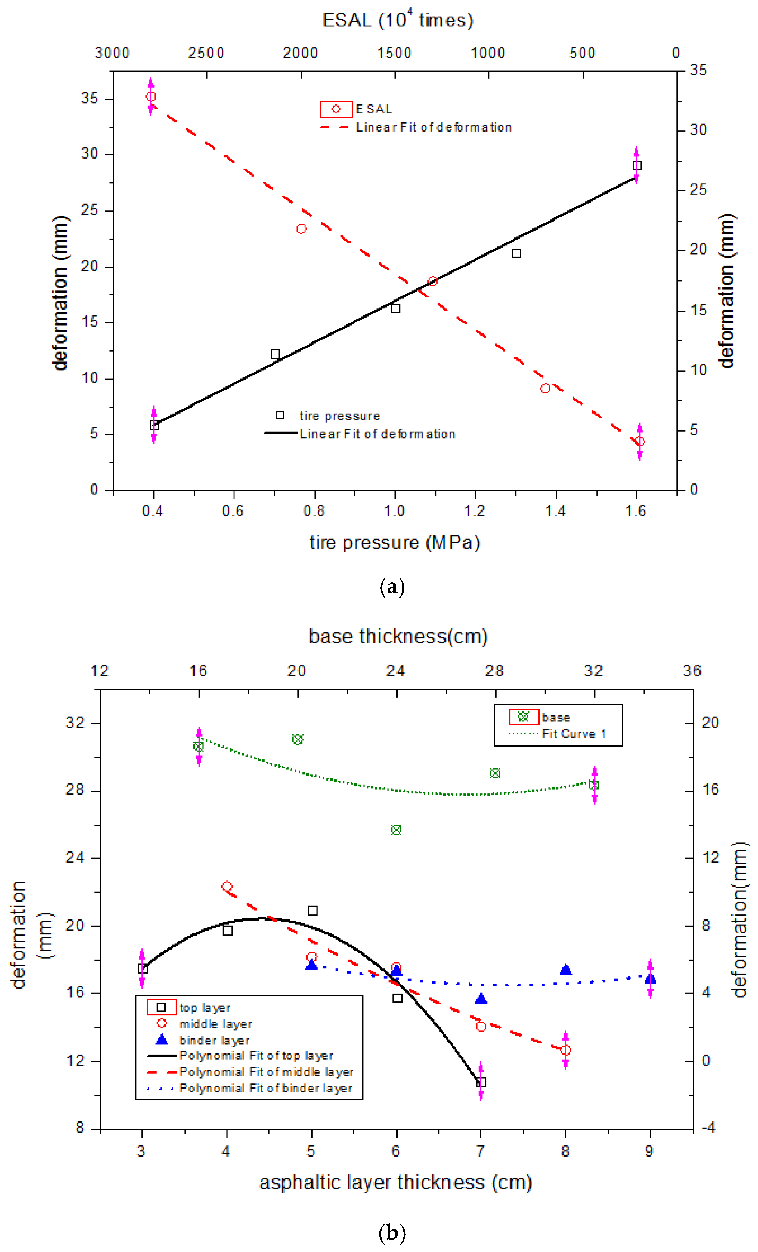
4.3. Rutting Prediction Model for HMAC Pavement in Curved and Sloped Road

Since there is no rutting predicting equation applicable to HMAC pavement in curved and sloped road in current literature, this research conducted multivariate regression on the simulating data and presented the following model. The correlation coefficient shows this model fits well with the simulating results.
R D = 0.0435 P 1.021 N 0.831 3.089 H u 0.5 7.650 ln H m + 1.685 ln 2 H b + 0.133 H b a + 13.677 ( R 2 = 0.959 )
where,
  • RD is the rutting depth (mm),
  • P is the tire pressure (MPa),
  • N is the ESAL number (104 times),
  • H u is the thickness of top asphaltic course (cm),
  • H m is the thickness of middle HMAC course (cm),
  • H b is the thickness of binder asphaltic course (cm),
  • H b a is the thickness of semi rigid base (cm).

5. Conclusions

This study modeled the permanent deformation of HMAC pavement in sloped and horizontally curved road using experimentation-based viscoelastic mechanics. Some primary conclusions are as follows.
(1)
The maximum rutting depth and bump height of HMAC pavement in curved and sloped road were greater than those in straightaway. The downward pavement areas of curved and sloped road developed evident upheaval due to longitudinal friction force. In addition, the outside pavement of horizontal curve presented larger upheaval than the inner side due to sideway force.
(2)
Analysis shows the upper and middle asphaltic courses were more crucial to pavement anti-rutting performance in curved and sloped road since inclusion of longitudinal and transverse shear force changed pavement deformation characteristic and the potential rutting area had a tendency to move up.
(3)
A preliminary model to predict rutting in HMAC pavement with sloped and horizontally curved alignment was presented based on material and structural features of asphalt pavement in China today.
It should be noted that in this study there are still some issues that need to be further addressed. First, this research simply considered the deformation at 50 °C. Permanent deformations in a wider temperature range should be investigated for a better understanding of HMAC pavement behavior. Second, the dynamic loading effect as well as the intermittent loading was not considered in the simulation for simplicity, which could possibly lead to a larger deformation. The last point is that only six factors were chosen as the variable in the prediction model, and other factors such as modulus of the base, subbase and subgrade did not appear in the equation but were taken as fixed values. However, though limited to some extent, the aforementioned model could be used for engineering precision especially when confronted with common practice in China.
Finally, from the viewpoint of life cycle cost [33], technical measures such as putting strict traffic control on special road, using effective anti-rutting asphalt mixtures were strongly suggested to be taken into account in the construction of special road to cut the life cycle pavement cost.

Acknowledgments

This research was supported by the Fundamental Research Funds for the Central Universities in China(No. 310821163502), the 2016 Outstanding Doctoral Dissertation project of Fundamental Research Funds for the Central Universities in China (No. 310821165008), the Transportation Department of Shandong Province (No. 2008Y007) and the National Natural Science Foundation of China (No. 51008033).

Author Contributions

Mulian Zheng was in charge of the whole research plan and paper submission matters. The first author extends gratitude to Lili Han, Chongtao Wang and Zhanlei Xu for performing the experiment and analyzing test data, to Hongyin Li and Qinglei Ma for offering help in doing the experiment.

Conflicts of Interest

The authors declare no conflict of interest.

References

  1. Drescher, A.; Kim, J.R.; Newcomb, D.E. Permanent deformation in asphalt concrete. J. Mater. Civ. Eng. 1993, 5, 112–128. [Google Scholar] [CrossRef]
  2. Li, C.; Li, L. Criteria for controlling rutting of asphalt concrete materials in sloped pavement. Constr. Build. Mater. 2012, 35, 330–339. [Google Scholar] [CrossRef]
  3. Xu, T.; Huang, X. Investigation into causes of in-place rutting in asphalt pavement. Constr. Build. Mater. 2012, 28, 525–530. [Google Scholar] [CrossRef]
  4. Katicha, S.W.; Apeagyei, A.K.; Flintsch, G.W.; Loulizi, A. Universal linear viscoelastic approximation property of fractional viscoelastic models with application to asphalt concrete. Mech. Time-Depend. Mater. 2014, 18, 555–571. [Google Scholar] [CrossRef]
  5. Hofko, B. Addressing the permanent deformation behavior of hot mix asphalt by triaxial cyclic compression testing with cyclic confining pressure. J. Traffic Transp. Eng. 2015, 2, 17–29. [Google Scholar] [CrossRef]
  6. Zhao, Y.; Wang, L.; Chen, P.; Zeng, W. Determination of surface viscoelastic response of asphalt pavement. J. Eng. Mech. 2015, 141, 1–8. [Google Scholar] [CrossRef]
  7. Blab, R.; Harvey, J. Modeling measured 3D tire contact stress in a viscoelstic FE pavement model. Int. J. Geomech. 2002, 2, 271–290. [Google Scholar] [CrossRef]
  8. Fang, H.; Haddock, J.E.; White, D.E.; Hand, A.J. On the characterization of flexible pavement rutting using creep model-based finite element analysis. Finite Elem. Anal. Des. 2004, 41, 49–73. [Google Scholar] [CrossRef]
  9. Abed, A. Evaluation of rutting depth in flexible pavements by using finite element analysis and local empirical model. Am. J. Eng. Appl. Sci. 2012, 5, 163–169. [Google Scholar]
  10. Wu, S.; Wang, J.; Chen, T. Stress analysis of asphalt pavement on large longitudinal slope. J. Wuhan Univ. Technol. Transp. Sci. Eng. Ed. 2006, 30, 969–972. (In Chinese) [Google Scholar]
  11. Pei, J.Z.; Chen, Y.; Chang, M.F. Mechanism of rutting formation in long and steep climbing sections of asphalt pavement. In Proceedings of the ICCTP 2009: Critical Issues in Transportation Systems Planning, Development, and Management, Harbin, China, 5–9 August 2009; ASCE: St. Louis, MO, USA, 2009. [Google Scholar]
  12. Hajj, E.Y.; Tannoury, G.; Sebaaly, P.E. Evaluation of rut resistant asphalt mixtures for intersection. Road Mater. Pavement Des. 2011, 12, 263–292. [Google Scholar] [CrossRef]
  13. Yang, X.; Guan, H.; Zhang, Q.; Zhou, L. The rutting resistant surface course combination for continuous uphill section of expressway. In Proceedings of the GeoShanghai 2010 International Conference: Paving Materials and Pavement Analysis, Shanghai, China, 3–5 June 2010; ASCE: St. Louis, MO, USA, 2010. [Google Scholar]
  14. Yang, J.; Li, W. Finite element analysis of asphalt pavement on long-steep longitudinal slope. J. Traffic Transp. Eng. 2010, 10, 20–31. (In Chinese) [Google Scholar]
  15. Li, L.; Huang, X.; Wang, L.; Li, C. Integrated experimental and numerical study on permanent deformation of asphalt pavement at intersections. J. Mater. Civ. Eng. 2013, 25, 907–912. [Google Scholar] [CrossRef]
  16. Zheng, M.; Han, L.; Wang, F.; Mi, H.; Li, Y.; He, L. Comparison and analysis on heat reflective coating for asphalt pavement based on cooling effect and anti-skid performance. Constr. Build. Mater. 2015, 93, 1197–1205. [Google Scholar] [CrossRef]
  17. Capitão, S.; Picado-Santos, L. Assessing permanent deformation resistance of high modulus asphalt mixtures. J. Transp. Eng. 2006, 132, 394–401. [Google Scholar] [CrossRef]
  18. Petho, L. High modulus asphalt mix (EME) for heavy duty applications and preliminary laboratory test results in Australia. In Proceedings of the AAPA 15th International Flexible Pavements Conference, Brisbane, Australia, 22–25 September 2013. [Google Scholar]
  19. Ministry of Transport (MOT). Technical Specification for Construction of Highway Asphalt Pavement; JTG F40-2004; Ministry of Transport: Beijing, China, 2004.
  20. Espersson, M. Effect in the high modulus asphalt concrete with the temperature. Constr. Build. Mater. 2014, 71, 638–643. [Google Scholar] [CrossRef]
  21. Ebrahimi, M.G.; Saleh, M.; Gonzalez, M. Interconversion between viscoelastic functions using the Tikhonov regularisation method and its comparison with approximate techniques. Road Mater. Pavement Des. 2014, 15, 820–840. [Google Scholar] [CrossRef]
  22. Saboo, N.; Kumar, P. A study on creep and recovery behavior of asphalt binders. Constr. Build. Mater. 2015, 96, 632–640. [Google Scholar] [CrossRef]
  23. Park, S.W.; Kim, Y.R. Fitting prony-series viscoelastic models with power-law presmoothing. J. Mater. Civ. Eng. 2001, 13, 26–32. [Google Scholar] [CrossRef]
  24. Chen, J.; Zhou, C.; Wang, Z. Data processing and viscoelastic computation for creep test of asphalt mixture. J. Southeast Univ. Nat. Sci. Ed. 2007, 37, 1091–1095. (In Chinese) [Google Scholar]
  25. Che, F. HMAC Performance Evaluation and Numerical Simulation for Special Section Pavement. Ph.D. Thesis, Chang’an University, Xi’an, China, 2011. [Google Scholar]
  26. Ministry of Transport (MOT). Design Specification for Highway Alignment; JTG D20-2006; Ministry of Transport: Beijing, China, 2006.
  27. Huang, F. Permanent Deformation Simulation and Rutting Depth Prediction of Asphalt Pavement. Master’s Thesis, Southeast University, Nanjing, China, 2006. [Google Scholar]
  28. Kong, H. Study on the Optimum Design of Asphalt Pavement Structure in Long Steep Longitudinal Slope Section Based on Rutting Resistance. Master’s Thesis, Chang’an University, Xi’an, China, 2012. [Google Scholar]
  29. Zhang, Q.; Zeng, S.; Wu, C. Orthogonal design method for optimizing roughly designed antenna. Int. J. Antennas Propag. 2014, 2014, 586360. [Google Scholar] [CrossRef]
  30. Otto, K.N.; Antonsson, E.K. Extensions to the Taguchi method of product design. J. Mech. Des. 1993, 115, 5–13. [Google Scholar] [CrossRef]
  31. Fraley, S.; Oom, M.; Terrien, B.; Zaleskwi, J. Design of Experiments via Taguchi Methods: Orthogonal Arrays. Available online: https://zh.scribd.com/document/133377816/Design-of-Experiments-via-Taguchi-Methods-Orthogonal-Arrays (accessed on 10 December 2016).
  32. Zheng, M.; Han, L.; Qiu, Z.; Li, H.; Ma, Q.; Che, F. Simulation of permanent deformation in high modulus asphalt pavement using Bailey-Norton creep law. J. Mater. Civ. Eng. 2016, 28, 1–11. [Google Scholar] [CrossRef]
  33. Praticò, F.G.; Casciano, A.; Tramontana, D. Pavement life cycle cost and asphalt binder quality: A theoretical and experimental investigation. J. Constr. Eng. Manag. 2011, 137, 99–107. [Google Scholar] [CrossRef]
Figure 1. Gradation curves of the aggregates.
Applsci 07 00331 g001
Figure 2. Appearance of high-modulus additive.
Applsci 07 00331 g002
Figure 3. Deformation–time curve of the specimen.
Applsci 07 00331 g003
Figure 4. Creep strain–time curve of the specimen.
Applsci 07 00331 g004
Figure 5. Creep compliance–time curve of the simulation and creep test.
Applsci 07 00331 g005
Figure 6. Pavement force analysis in curved and sloped road. (a) Longitudinal section; (b) transverse section.
Applsci 07 00331 g006
Figure 7. Nephogram of permanent deformation in simple road.
Applsci 07 00331 g007
Figure 8. Nephogram of permanent deformation in curved ramp.
Applsci 07 00331 g008
Figure 9. Change of permanent deformation with factors and levels, (a) with tire pressure and ESAL; (b) with different layer thickness.
Applsci 07 00331 g009
Table 1. Burgers model parameters and its Prony series coefficients of different mixtures. AC, asphalt concrete; HMAC, high-modulus asphalt concrete.
Temp.MixtureModel ParameterProny Series Coefficient
E1 (MPa)E2 (MPa)η1 (GPa·s)η2 (GPa·s)g1g2τ1τ2
50 °CAC-254006874430.8690.13154.9101706.277
HMAC-16700166190570.9320.06863.2901831.429
HMAC-20800132220680.9080.09259.2292399.987
Table 2. Pavement longitudinal friction force under different slopes (in pressure unit) 1.
Design Speed (km/h)1201008060403020
Max slope I (%)3456789
Slope angle A (°)1.7182.2912.8623.4344.0044.5745.143
psinA (MPa)0.0210.0280.0350.0420.0490.0560.063
pcosA (MPa)0.7070.7060.7060.7060.7050.7050.704
fl = psinA + φpcosA (MPa)0.3750.3810.3880.3950.4020.4090.415
1 φ is rolling friction coefficient. Wheel Contact Pressure p (MPa): Standard Axle Load BZZ100, p = 0.707 MPa, φ = 0.5.
Table 3. Structural thickness and basic parameters of the pavement model.
Structural LayersThickness (cm)Resilient Modulus (MPa)Poisson Ratio
Asphaltic layersTop layer3–7using viscoelastic parametersusing viscoelastic parameters
Middle course4–8
Binder course5–9
Semi rigid base16–3214000.25
Subbase206000.25
Subgrade700600.25
Table 4. Accumulated loading time and deformation recovering time. ELAL, equivalent single axle load.
ESALs (104 times)Accumulated Loading Time (s)Recovery Time (s)
20057602400
70020,1608400
130037,44015,600
200057,60024,000
280080,64033,600
Table 5. Six factors and the corresponding levels.
FactorLevel
12345
P1-tire pressure (MPa)0.40.71.01.31.6
P2-ESAL (104 times)200700130020002800
P3-top layer thickness (cm)34567
P4-middle course thickness (cm)45678
P5-binder course thickness (cm)56789
P6-base thickness (cm)1620242832
Table 6. Orthogonal array and results of intuitive analysis on 25 trials.
Experiment No.FactorDeformation (mm)
P1P2P3P4P5P6
11111111.308
21222223.894
31333336.350
41444447.136
515555510.643
62123452.603
72234516.467
823451210.033
924512313.476
1025123428.690
113135243.550
1232413510.128
1333524113.940
1434135224.299
1535241329.557
164142535.095
174253148.055
1843142519.172
1944253125.092
2045314249.035
215154327.977
2252154314.072
2353215437.823
2454321539.232
2555432146.460
Kj129.33120.53387.541111.77088.18593.267-
Kj261.26942.61698.96990.85186.55295.238-
Kj381.47487.318104.63487.76778.23768.550-
Kj4106.449109.23578.85270.30986.78685.254-
Kj5145.564164.38554.09163.39084.32781.778-
K ¯ j 1 5.8664.10717.50822.35417.63718.653-
K ¯ j 2 12.2548.52319.79418.17017.31019.048-
K ¯ j 3 16.29517.46420.92717.55315.64713.710-
K ¯ j 4 21.29021.84715.77014.06217.35717.051-
K ¯ j 5 29.11332.87710.81812.67816.86516.356-
Range23.24728.77010.1099.6761.9905.338-

