1. Introduction
Comfort is a decisive factor for motorcycle riders when selecting a helmet for use in warm climates [
1,
2]. Given the lack of appropriate headgear, riders may dispense with a helmet entirely. For example, in a recent study of novice motorcycle riders in New South Wales (NSW), Australia, it was found that 10% of the subjects did not wear a helmet while riding in traffic [
3]. Moreover, self-reported helmet use among teenage motorcyclists in Taiwan was found to be just 55% in summer months [
4]. Accordingly, when designing helmets for motorcycle use, it is imperative that a compromise is reached between user safety and user comfort.
In general, South East (SE) Asia provides an ideal location for studying the efficacy of helmets, since motorcycles and scooters represent the most common form of transportation [
5]. Various helmet designs are available, including full-face, open-face, and half-face models. The choice of helmet depends on the particular preferences of the user, regarding comfort and safety. Due to the hot and humid conditions which are prevalent throughout SE Asia, open-face and half-face helmets tend to be the most frequently worn. However, wearers of open-face or half-face helmets suffer head injuries more than twice as often as wearers of full-face helmets [
6]. Of the two types of helmet, open-face helmets provide a better user safety level, but at the expense of comfort. Thus, it is necessary to improve the ventilation efficiency of open-face helmets, without sacrificing their impact performance.
Many different safety standards have been proposed for motorcycle helmets, including ECE R22.05, Snell M2010, and DOT FMVSS 218 [
7]. In general, these standards present the requirements for the performance of a helmet, taking into consideration impacts to the top of the helmet at various energies and speeds [
8]. However, while the strict test conditions prescribed in these standards are necessary to facilitate standardized testing, the collected data are only of limited use in analyzing actual crash scenarios, in which motorcycle helmets face widely varying impact angles, impact surfaces, and impact speeds. Accordingly, De Marco et al. [
6] proposed a new test protocol for examining the crashworthiness performance of helmets under impacts at oblique angles. The impact performance of ECE-approved helmets has been investigated at various speeds in the range of 0.5 to 10.0 m/s [
9]. However, few studies have investigated the impact performance of motorcycle helmets under realistic surface conditions (e.g., asphalt or vehicle bodies), or have examined the performance of common Asian helmets at typical impact speeds.
Experimental investigations provide a detailed insight into the mechanical response of motorcycle helmets under impact. However, experimental tests are time-consuming and expensive. Moreover, it is impossible to accurately recreate all of the crash scenarios which may occur in real life. Consequently, the use of finite element analysis (FEA) simulations to evaluate the conformance of different helmet designs to safety standards, has attracted an increasing amount of attention in recent years. Liu et al. [
10,
11] performed LS-DYNA simulations of the impact response of several common helmet designs, based on the material mechanical properties obtained from experimental quasi-static impact tests. In addition, Pinnoji et al. [
11] used a numerical modeling approach to evaluate the head injury criterion and brain stress for open-face motorcycle helmets, in which the conventional thermoplastic outer shell was replaced with a lightweight metal foam.
Previous studies on helmet safety generally focus on just one particular helmet design (e.g., full-face or open-face), and investigate the performance of the helmet with regard to specific safety regulations. However, the present group recently investigated the impact performance of three different types of motorcycle helmet (full-face, open-face, and half-face), with respect to three different helmet safety regulations (ECE R22.05, Snell M2010, and DOT FMVSS 218) [
8,
12]. In the present study, a further investigation is performed, focusing on the head protection performance of a novel open-face helmet incorporating three parallel ventilation slots into the upper-head region. By contrast, the present study investigates the impact performance of various types of motorcycle helmet with respect to three different helmet safety regulations (ECE R22.05, Snell M2010. and DOT FMVSS 218). Four helmet designs are considered, namely full-face, open-face, half-face, and a novel open-face design in which three parallel ventilation slots are incorporated into the upper-head region of the helmet structure.
This study commenced by simulating the linear headform acceleration induced in a drop test, performed at an impact speed of approximately 6 m/s by using a full-face helmet. The validity of the simulation results was demonstrated by comparing the acceleration profile during the simulated impact event with that measured experimentally. Additional simulations were then performed to evaluate and compare the performance of the four helmet designs under identical impact conditions.
2. Materials and Methods
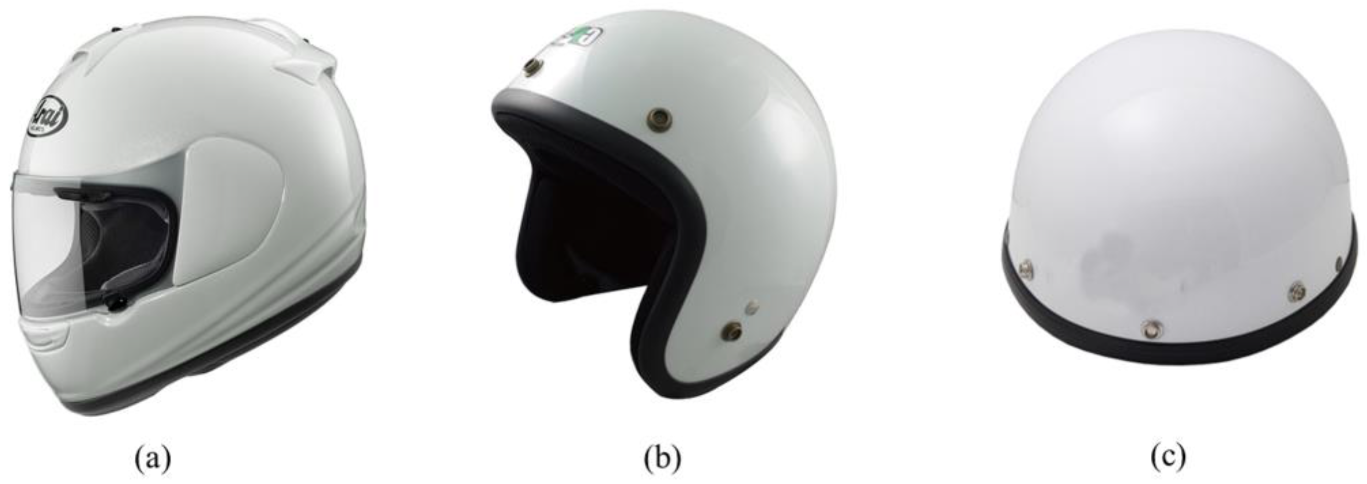
Figure 1 shows the three traditional helmet designs considered in the present study. The full-face helmet covers the entire head, and comprises a rear section which covers the back of the skull and the top of the neck, a protective section which covers the top of the head and the cheekbones, and a further protective section which covers the jaw bone and chin (
Figure 1a). The open-face helmet covers the same area as the full-face helmet, but leaves part of the face (usually the lower chin) exposed (
Figure 1b). Finally, the half helmet has essentially the same design as the open-face helmet, but leaves the lower rear region of the head and the cheeks exposed (
Figure 1c).
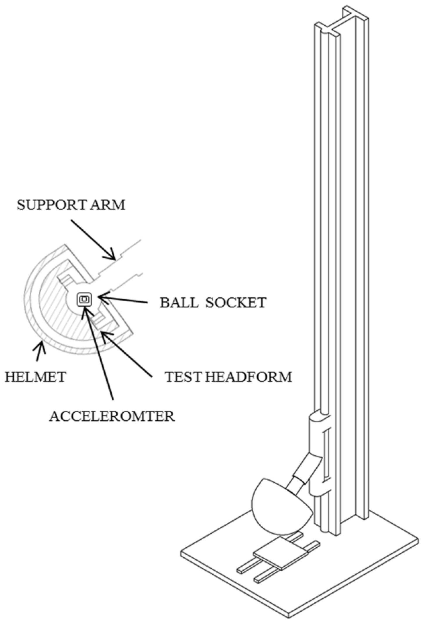
The crashworthiness of motorcycle helmets is generally evaluated by means of free-fall drop tests, in which the helmet is positioned on a test headform and then dropped vertically, onto a fixed steel anvil.
Figure 2 presents a schematic illustration of the test rig used in the present study to investigate the impact performance of the full-face helmet. When performing the test, the helmet was placed over an aluminum headform attached to a ball arm and was then dropped onto a flat tetragonal anvil containing a circular impact area with a diameter of 127 mm. The moving assembly (minus the helmet) had a total mass of 5 kg and exhibited no resonant frequencies below 2000 Hz. The free-fall height of the ball arm was set to 1830 mm; resulting in an impact velocity of 598.9 cm/s. The helmet was positioned on the headform in such a way that the impact occurred against the top of the helmet; thereby avoiding the air vent regions. The headform acceleration during impact was measured using a MAU-1055 accelerometer (Superpro Technology Corp., Taipei, Taiwan).
The present study evaluated the performance of the four helmets (i.e., full-face, open-face, half-face, and open-face with ventilation) with regards to three different standards, namely ECE R22.05, Snell M2010, and DOT FMVSS 218. As shown in
Table 1, all three standards prescribe a peak acceleration limit for the headform center of gravity (COG), while the DOT standard imposes an additional limit on the acceleration duration [
8].
2.1. Peak Linear Acceleration
The peak linear acceleration described in helmet safety standards is essentially the maximum allowed acceleration of the COG of the headform during impact. As shown in
Table 1, the peak acceleration is stated as a multiple of the gravitational acceleration constant G (1 G = 9.81 m/s
2). The peak acceleration value ignores the duration of the impact. However, there is a strong body of evidence to suggest that the severity of head injuries depends not only on the magnitude of the impact, but also on the duration over which the impact energy acts [
13]. Thus, DOT FMVSS 218 not only prescribes a maximum headform acceleration (400 G), but also places limits on the time for which certain accelerations are permitted to exist (e.g., an acceleration of more than 200 G should not persist for more than 2 ms) [
14].
2.2. Finite Element Models
Helmets were purchased from a commercial vendor in Taiwan and were scanned using a three-dimensional (3D) optical measurement system (COMET 5, Steinbichler Optotechnik, Munich, Germany). For each helmet, 3D modeling data were obtained through eight scans, performed at intervals of 45°. The eight scans were combined into a single 3D model using Geomagic Studio software (Geomagic, Morrisville, NC, USA). The dimensions of the helmet and solid structures in the 3D model were determined using SolidWorks software (version 2013, Dassault Systemes Corp., Waltham, MA, USA). Finally, the 3D model was converted to a finite element (FE) format, using ABAQUS software (Version 6.12, Dassault Systemes Corp., Waltham, MA, USA). When constructing the models, the small holes in the inner and outer surfaces of the helmet (e.g., those used for visor or chin strap attachment purposes) were retained, since they act as stress raisers, therefore affecting the mechanical response of the helmet. However, features such as air vents and plate surfaces, which are only used for aerodynamics and styling purposes, were excluded, in order to simplify the modeling process.
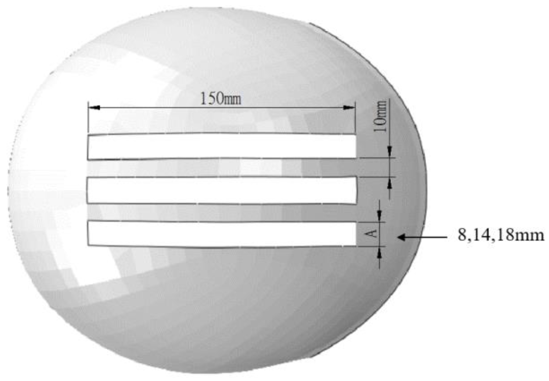
In addition to the three traditional helmet designs described above, the present study also considered a novel open-face helmet design in which three parallel ventilation slots were incorporated into the upper-head region. As shown in
Figure 3, each ventilation slot had a length of 150 mm and was separated from its neighbor by a distance of 10 mm. To determine the helmet design with an optimal compromise between user safety and user comfort, the simulations considered three different slot widths, namely 8, 14, and 18 mm.
2.3. Finite Element Models
Each of the helmets considered in the present study consisted of two components, namely a hard outer shell and a foam inner liner. When performing the simulations, the shell and liner were assumed to be fabricated of Acrylonitrile Butadiene Styrene (ABS) and Expanded Poly-Polystyrene (EPS), respectively. The material data for the ABS shell were taken from previous studies [
9,
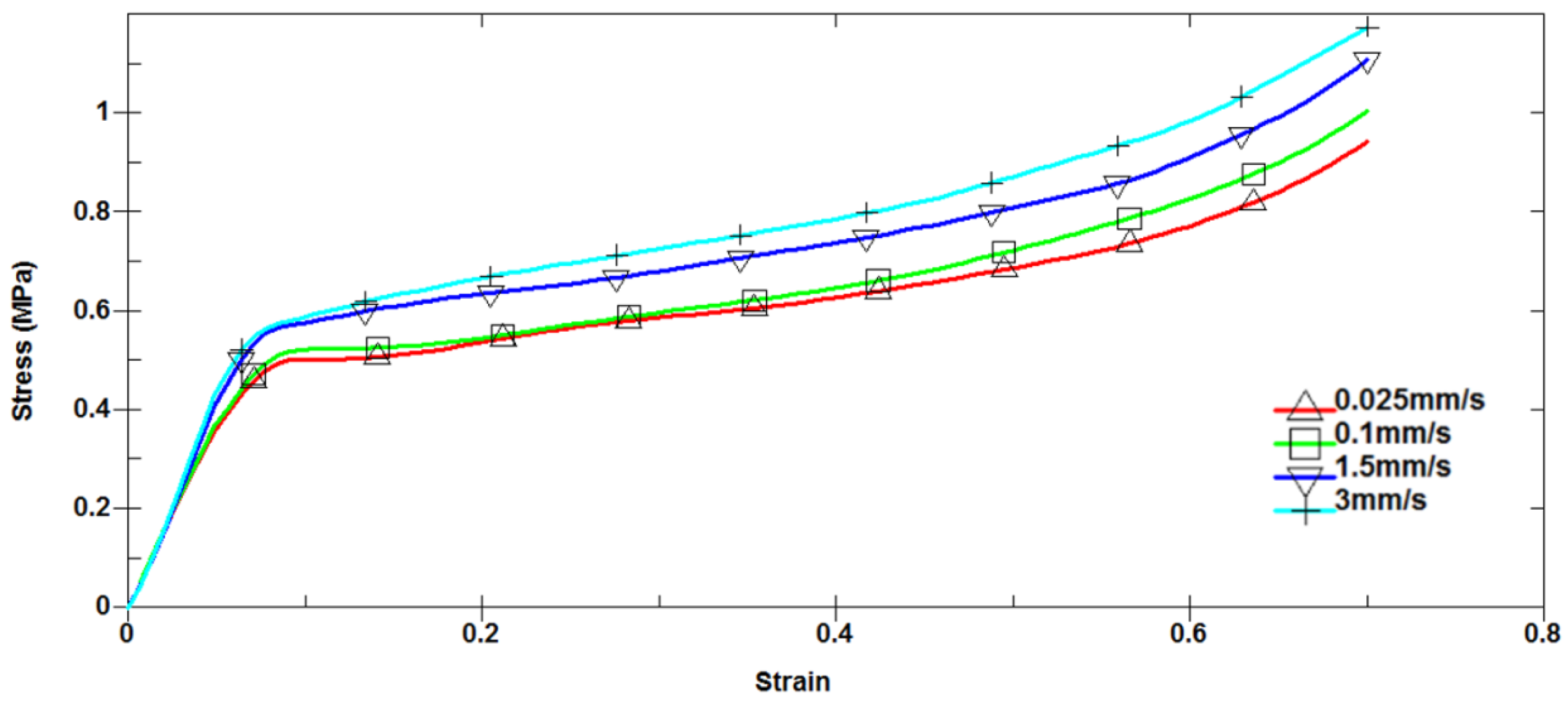
15]. Similarly, the material properties of the foam liner were derived from the stress-strain curves presented in previous experimental studies by Liu et al. [
15]. As shown in
Figure 4, the static stiffness of the foam material linearly increased with an increasing compression rate, in both the elastic regime and the plastic regime. It is worth noting that this finding is consistent with the results of Chang et al. [
16], based on an empirically-derived constitutive model. The headform was modeled using solid hexahedron elements with single integration points and was assumed to be fabricated of aluminum. The model stiffness was deliberately increased, in order to prevent elastic deformation of the headform during impact; thereby interfering with the foam energy absorption results. (Note that while the headform could have been modeled using a rigid material, contact with elastic materials is more stable).
Table 2 summarizes the material properties used for the various helmet components in the simulations.
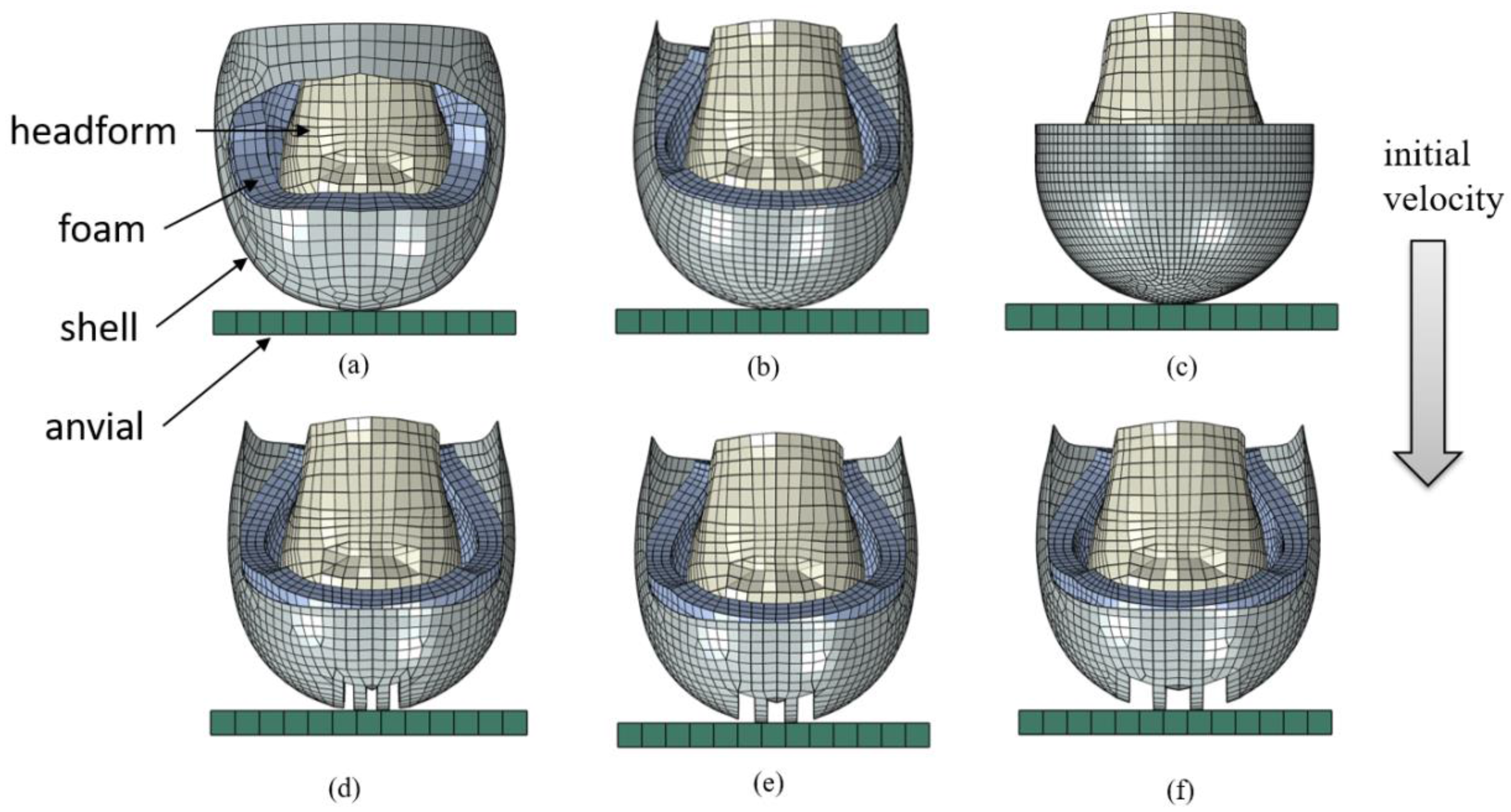
Figure 5a–c shows the FEA models of the full-face, open-face, and half helmets, respectively. (Note that the FE model of the prototype open-face helmet is shown in
Figure 5d–f.) The model used to simulate the impact test for the full-face helmet consisted of a total of 8950 elements, including 1864 quadrilateral type S4R elements for the ABS shell, 4775 hexahedral type C3D8R elements for the EPS liner, 1332 rigid hexahedral type C3D8R elements for the headform, and 979 hexahedral type C3D8R elements for the flat steel anvil. For the impact tests performed with the remaining helmets, the headform and anvil models were unchanged, and the open-face and half-face helmet models consisted of 2532/4875 and 2189/8784 (S4R/C3D8R) elements, respectively. For each helmet, the headform acceleration during impact was computed in the
Z-axis direction, over an interval of 20 ms. The simulations were performed using ABAQUS/Explicit software with the large deformation option.
2.4. Contact Conditions
The contact surfaces of the helmet models were implemented using general automatic contact type elements. The 3D dynamic FE models involved multipoint, tie, and contact constraints. Moreover, the relative motion between the contact surfaces was constrained to the parallel direction. In addition, penalty contact algorithms were applied at the interfaces, and automatic surface-to-surface contact options were used between the EPS foam liner and the ABS shell, as well as between the foam and the headform model, to prevent interpenetration. A friction coefficient of 0.3 was assigned between the outer shell and the foam liner, and between the foam liner and the headform [
17]. Finally, in accordance with the recommendations of the ABAQUS manual, the shear of the scalp layer prior to the slip was modeled using an elastic slip condition.
3. Results
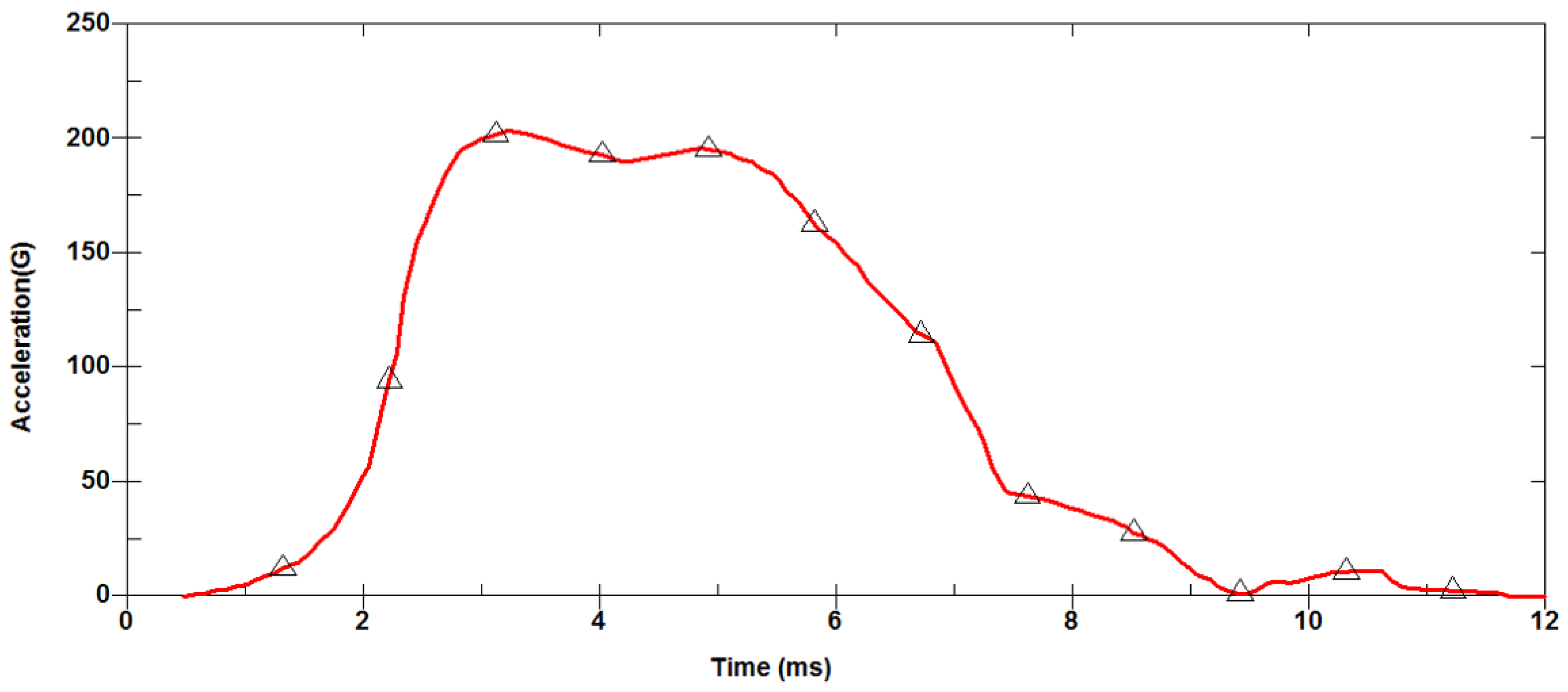
Figure 6 shows the experimental results obtained for the variation of the peak headform acceleration over time, in the impact test conducted using the full-face helmet. The acceleration increases rapidly to a maximum value of 204 G at 3 ms, falls to around 190 G at 4 ms, and then increases once again to a local maximum value of 196 G at 5 ms. The acceleration then reduces to zero, after approximately 12 ms. A small local acceleration peak is observed at approximately 11 ms.
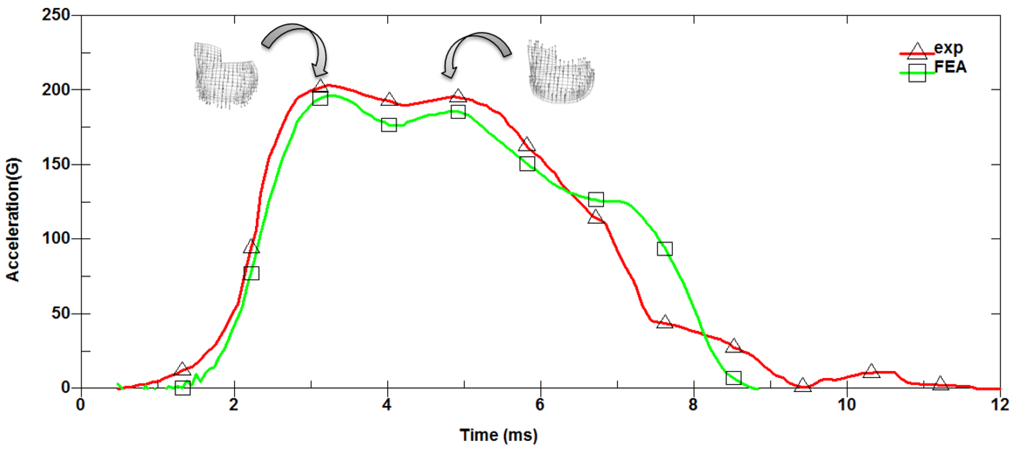
Figure 7 compares the simulation results for the headform acceleration in the full-face helmet impact test with the experimental results. It is observed that the simulated value of the global maximum acceleration (197 G) is slightly lower than the experimental value (204 G). Similarly, the simulated value of the local acceleration peak (186 G) is also slightly lower than the experimental value (196 G). The tendency of the simulation model to understate the acceleration is most likely due to the model error value. However, in general, the simulated acceleration profile is in good qualitative agreement with the experimental results, thus confirming the general validity of the modeling method.
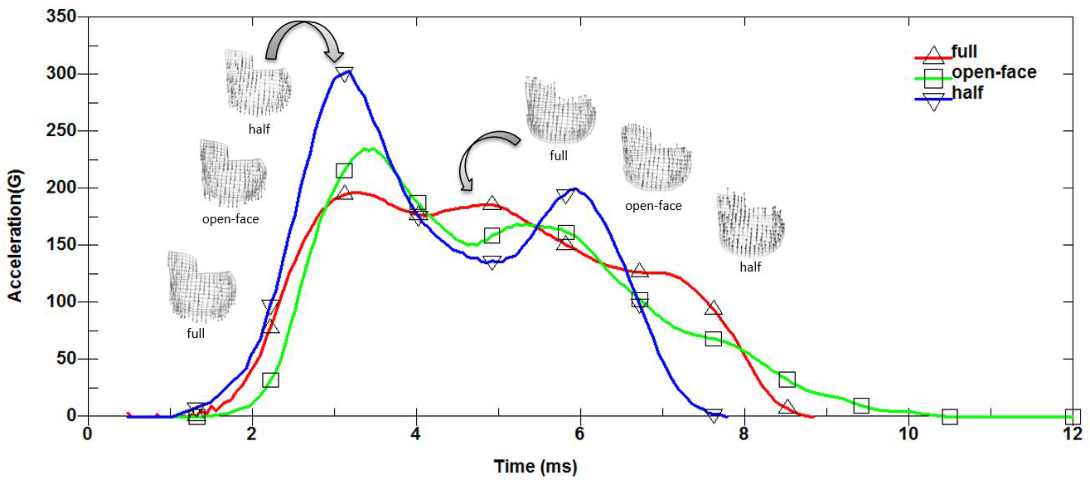
Figure 8 presents the simulated headform acceleration profiles for the full-face, open-face, and half-face helmets, given an impact speed of 6 m/s. A good general agreement exists between all three profiles. However, a close inspection reveals some subtle differences between them. For example, the half and open-face helmets have peak accelerations of 303 G and 235 G, respectively, whereas the full-face helmet has a much lower peak acceleration of 197 G.
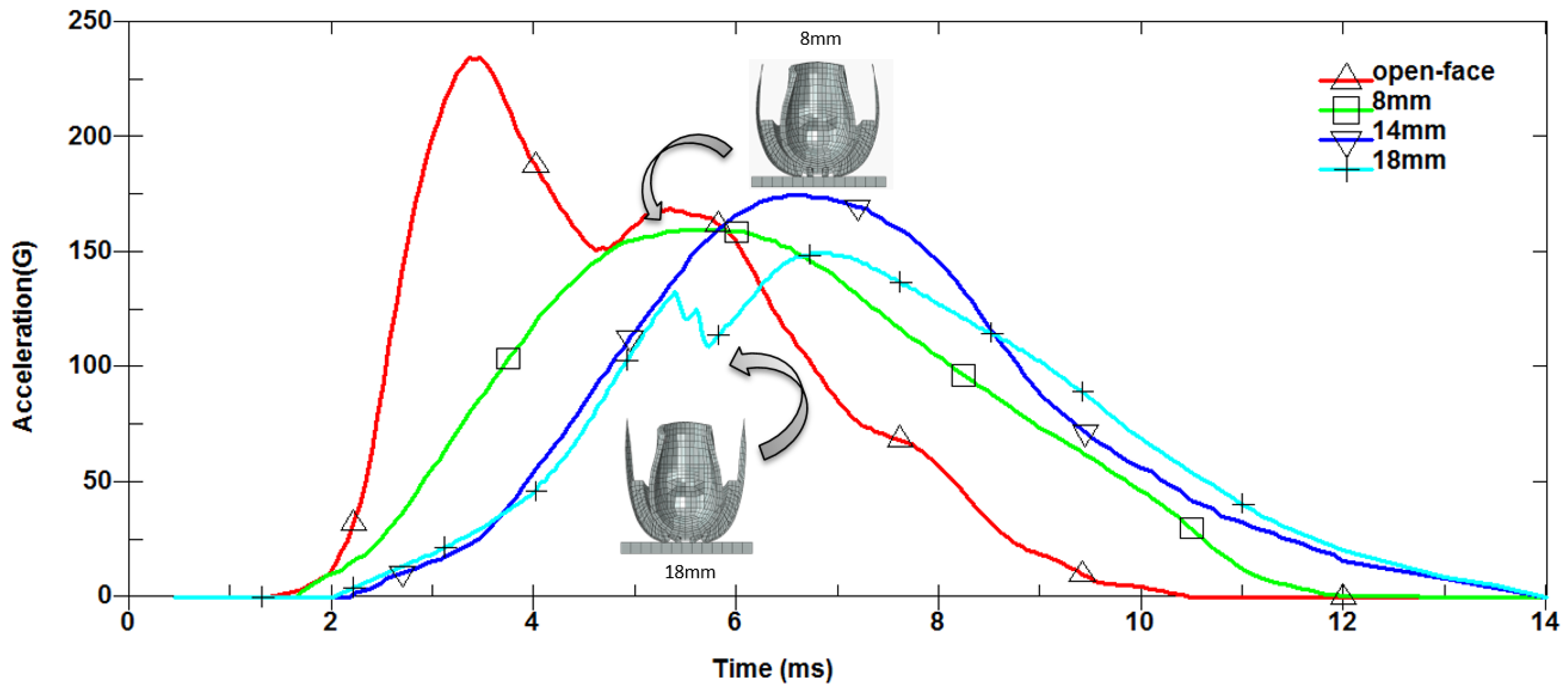
Figure 9 compares the simulated acceleration profile of the original open-face helmet, with the profiles obtained for the prototype helmet design with ventilation slot widths of 8 mm, 14 mm, and 18 mm, respectively. As discussed above, the original open-face helmet has a maximum acceleration value of approximately 235 G. In contrast, the peak acceleration value of the prototype helmet is 160 G for a slot width of 8 mm, 175 G for a slot width of 14 mm, and 150 G for a slot width of 18 mm. In other words, for all values of the ventilation slot width, the peak acceleration experienced by the headform during impact is lower than that produced by the original open-face helmet design.
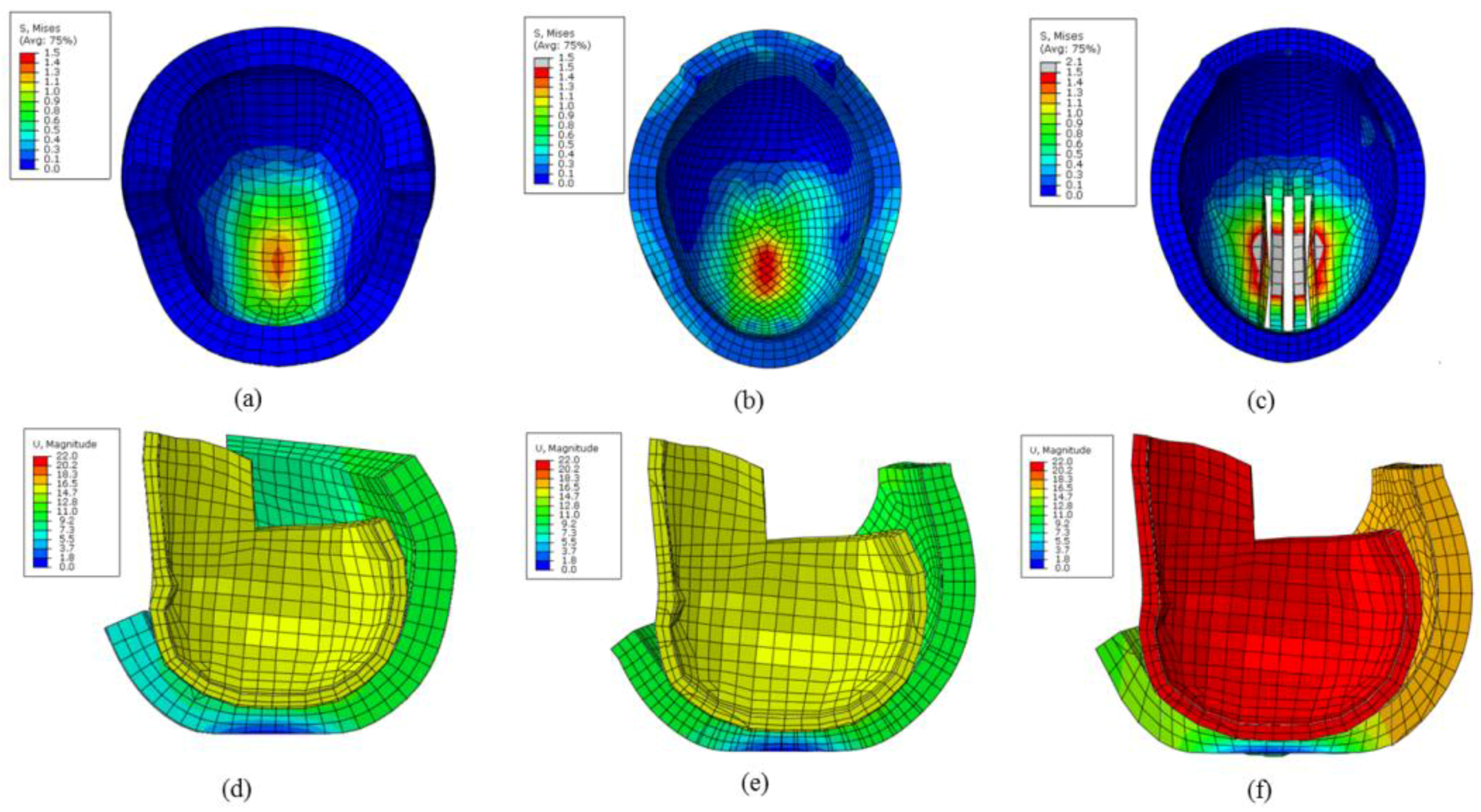
Figure 10 shows the magnitude of the stress and displacement contours of the full, open-face, and 8-mm ventilation slot helmets. The level of stress recorded for the 8-mm ventilation slot helmet is 2 Mpa, whereas the displacement value is 21 mm. However, in the case of a full helmet, the level of stress is 1.3 Mpa, whereas the displacement value is 15 mm; however, for an open-face helmet, the level of stress is 1.5 MPa and the displacement value is approximately 16 mm. Thus, the 8-mm ventilation slot helmet possesses the ability to achieve buffer distances that absorb energy.
4. Discussion
The experimental and simulation results show two main peaks in the headform acceleration profile for the full-face helmet: an initial peak with a value of 204 G/197 G (experimental/simulation) after nearly 3 ms, and a second peak with a value of 196 G/186 G (experimental/simulation) after approximately 5 ms (
Figure 6 and
Figure 7). The first peak corresponded to the initial moment of contact between the helmet and the anvil block, when the helmet first started to slow down and undergo rapid deceleration. In contrast, the second peak corresponded to the point of full contact between the helmet and the block. In particular, the second peak could be attributed to the high-density rebound of the liner material (EPS foam), which limited the amount of energy that could be absorbed by the liner, thus increasing the energy transferred to the shell upon impact with the anvil [
18].
The simulation results presented in
Figure 8 show that the full-face helmet resulted in a lower peak headform acceleration (197 G) than either the open-face helmet (235 G) or half-face helmet (303 G). Thus, of the three helmets, the full-face design provides the best user protection. Notably, however, both the full-face and open-face helmets were observed to satisfy the ECE standard (275 G), whereas all three designs were determined to conform to the Snell standard (300 G) and DOT standard (400 G). In general, half-face helmets are more easily fabricated than open-face (or full-face) helmets, because the need for additional vents and cooling structures is removed in such helmets. However, according to the results presented in
Figure 8, the peak headform acceleration associated with the use of the half-face helmet (303 G) was approximately 54% higher than that associated with the use of the full-face helmet (197 G) and 29% higher than that associated with the use of the open-face helmet (235 G). Hence, from a safety perspective, the use of a half-face helmet should be avoided. In other words, the open-face design provides a better compromise between rider safety and rider comfort under warm conditions.
Helmets protect the head in two ways. First, the hard outer shell resists penetration and absorbs the initial shock. Subsequently, the softer foam liner progressively absorbs the impact energy by gradually collapsing. Previous studies have shown that the stress–strain response of polystyrene foam contains three characteristic regions under compression loading, namely linear elasticity (because of cell wall bending), plastic deformation (because of cell wall collapse), and densification (because of contact and crushing between opposing cell walls). Thus, a study reported that the force rises rapidly at strains greater than approximately 80% [
19]. The results presented in
Figure 9 show that the prototype open-face helmet with ventilation slots resulted in a lower peak headform acceleration than the original open-face design, irrespective of the ventilation slot width. This finding is reasonable because the ventilation slots in the shell/liner increase the space available for the foam liner to freely deform under impact, thus increasing the amount of impact energy that can be absorbed prior to densification. Notably, however, the ability of the liner to absorb the impact energy is not directly correlated with the ventilation slot width. For example, the maximum headform acceleration associated with a slot width of 14 mm (175 G) was greater than that associated with a smaller slot width of 8 mm (160 G). This result is reasonable because the absorbed energy is greater at a smaller width, thus enabling the helmet to withstand more impact. The minimum headform acceleration (150 G) was obtained using the maximum slot width of 18 mm. However, as shown in
Figure 9, the acceleration profile obtained for this slot width had a two-peak characteristic (whereas those obtained for the 8-mm and 14-mm designs only had one). This suggests that, given a lower level of support of the foam liner by the outer shell, the foam more readily enters the densification region of the stress–strain curve, consequently resulting in the partial collapse of the liner material. Although the subsequent peak headform acceleration (150 G) was lower than that of the other two designs, the ability of the liner to support the head during impact was reduced, thus increasing the risk of head injury. Consequently, of the three prototype designs, the results presented in
Figure 9 suggest that a ventilation slot width of 8 mm yields the best compromise between rider comfort and rider safety.
The peak headform acceleration associated with the use of the 8-mm ventilation slot width (160 G) was approximately 32% lower than that of the original open-face design (235 G) and 19% lower than that of the full-face helmet (197 G). Thus, the suitability of the proposed open-face prototype design for head protection in warm climates is further confirmed.
Figure 10 shows the stress and displacement contours for the three helmet models. The 8-mm ventilation slot model exhibits significant stress and displacement induced in the headform and helmet. Thus, the suitability of the proposed open-face prototype design for head protection in warm climates is further confirmed.
5. Conclusions
Existing motorcycle helmets generally provide an adequate performance level in terms of protecting the head during impact. However, even the most sophisticated and expensive of helmets are ineffective when not actually worn. Many studies have shown that wearers in hot climates tend to dispense with helmets for comfort. Thus, during the design of a motorcycle helmet, it is necessary to consider not only the protection afforded to the rider, but also the level of comfort. Accordingly, this study proposes a novel open-face helmet design in which three parallel ventilation slots are incorporated into the upper-head region of the helmet structure. The impact performance level of the proposed helmet was compared with those of three traditional helmet designs (full-face, open-face, and half-face helmets), by simulating free-fall drop impact tests at a speed of approximately 6 m/s. The results obtained in this study support the following conclusions:
Of the three traditional helmet designs (full-face, open-face, and half-face helmets), the half helmet resulted in the greatest peak headform acceleration (303 G), whereas the full-face helmet resulted in the lowest acceleration (197 G). Thus, although the half-face helmet can provide the greatest degree of user comfort, because of its lighter weight and better ventilation, it offered the poorest head protection performance out of the three designs. Notably, however, all of the three helmets were seen to satisfy the Snell standard (300 G) and DOT standard (400 G) for the maximum headform acceleration.
The peak headform acceleration of the open-face helmet (235 G) was just 19% higher than that of the full-face helmet (197 G). Thus, if the additional protection afforded to the chin and frontal-face area of the rider in the event of an accident is disregarded, an open-face helmet provides both a good level of protection, and an improved level of user comfort. Consequently, it is a reasonable choice for motorcycle riders in warm climates. However, further research is required to improve the ventilation performance of open-face helmets, in order to enhance the number of riders which are actually wearing them.
The proposed prototype open-face helmet with ventilation was observed to result in a lower peak headform acceleration than the original open-face helmet, irrespective of the slot width (8, 14, or 18 mm). The improved energy absorption performance of the proposed design was attributed to the greater freedom of movement available to the liner; this freedom of movement enables the liner to deform under impact, due to the absence of foam in the slot regions of the helmet.
Of the three open-face helmets with ventilation slots, the helmet with the slot width of 18 mm resulted in the lowest peak headform acceleration (150 G). However, the acceleration profile for this helmet was observed to have a two-peak characteristic, indicating the partial collapse of the liner under impact, and thus, a lower protection afforded to the head. Therefore, the optimal prototype design was determined to be that with a ventilation slot width of 8 mm, for which the acceleration profile had a single-peak characteristic and a maximum headform acceleration of 160 G.
The peak headform acceleration associated with the use of the 8-mm ventilation slot width (160 G) was approximately 32% lower than that of the original open-face design (235 G) and 19% lower than that of the full-face helmet (197 G). Therefore, this confirms the feasibility of the proposed design for motorcycle riders in warm climates.
In general, the present results indicate that of all the helmet designs considered in this study, the full-face design provides the rider with maximum protection in the event of an accident. However, comfort is a decisive factor when selecting a helmet for use in SE Asia and other warm climes. Thus, effective helmet design must consider both user protection and user comfort. The simulation results presented in this study suggest that open-face helmets with additional ventilation slots in the upper-head region may allow both requirements to be simultaneously achieved. However, further research is required to explore the optimal size and configuration of the ventilation slots (e.g., their number, size, arrangement, and positioning).


