Article

Effects of a Nano-Silica Additive on the Rock Erosion Characteristics of a SC-CO2 Jet under Various Operating Conditions

1
School of Power and Mechanical Engineering, Wuhan University, Wuhan 430000, China
2
Hubei Key Laboratory of Water Jet Theory and New Technology, Wuhan University, Wuhan 430000, China
*
Author to whom correspondence should be addressed.
Appl. Sci. 2017, 7(2), 153; https://doi.org/10.3390/app7020153
Submission received: 6 December 2016 / Revised: 31 January 2017 / Accepted: 3 February 2017 / Published: 8 February 2017
(This article belongs to the Special Issue The Applications of Supercritical Carbon Dioxide)

Abstract

:
In order to improve the erosion capacity of a supercritical carbon dioxide (SC-CO2) jet, the influence of a nano-silica additive on the rock erosion characteristics was experimentally investigated. By impinging the SC-CO2 jets with nano-silica mass fractions of 0 wt % (pure SC-CO2 jet), 3 wt %, 6 wt %, 9 wt %, 12 wt %, 15 wt %, and 18 wt % on specimens of red sandstone, the erosion volumes under various operating conditions were measured and analyzed. Results show that an appropriate amount of nano-silica additive can greatly enhance the erosion ability of a SC-CO2 jet. The effect on the erosion ability largely depends on the operating conditions. For instance, when the other conditions are fixed, 6 wt %, 9 wt %, 12 wt %, and 15 wt % were the optimum mass fractions, successively, with the inlet pressure increasing from 30 MPa to 60 MPa. With the increase in ambient pressure, the optimum mass fraction is unchanged under the constant inlet pressure, while it increases under the constant pressure drop. Additionally, the optimum mass fraction decreases when the fluid temperature increases. In addition, the optimal standoff distances are about five times the nozzle diameter of the nano-silica SC-CO2 jet, and three times for the pure jet. This research provides a new method for effectively enhancing the rock erosion performance of a SC-CO2 jet.

1. Introduction

Supercritical carbon dioxide (SC-CO2) is an intermediate state between gas and liquid for carbon dioxide, when the pressure and temperature are both above the critical point (Pc = 7.38 MPa and Tc = 304.13 K) [1,2]. Due to its unique properties and the relatively easy critical conditions which need to be obtained, SC-CO2 fluid has been widely studied and used in numerous fields [3,4,5,6]. In recent years, SC-CO2 fluid, which has many advantages for improving the rates of penetration and single well recovery, has been applied in the field of drilling and completion engineering, especially for the exploitation of unconventional reservoirs [7,8,9,10]. Moreover, it is reported that a SC-CO2 jet has better rock erosion and fracturing capacity than a water jet does, thus, it has been widely considered as a promising and novel jet technology [11,12,13,14]. Besides, inside a reservoir bed, the dissolution of organic deposition by the seepage of SC-CO2 can increase the permeability of the reservoirs, and the absorbed natural gas can be displaced through competitive adsorption with SC-CO2 [15,16]. These processes help to reduce the blockage of oil and gas flow, and then enhance recovery [17,18]. In addition, using SC-CO2 as a drilling fluid will contribute to the reduction of greenhouse gas emissions and the pollution of water resources [19].
In the late 1990s, Kolle [20] first used SC-CO2 as the drilling fluid in coiled-tubing drilling technology, as shown in Figure 1, and conducted initiative research on the rock erosion of a SC-CO2 jet. The results showed that the rock erosion capacity of a SC-CO2 jet is stronger than that of a water jet, and that the threshold pressure is lower than that of a water jet. They also concluded that the rate of penetration in Mancos Shale, and the drilling specific energy using a SC-CO2 jet, is 3.3 times and approximately 20% of that when using a water jet, respectively. In recent years, to make better use of a SC-CO2 jet by maximally increasing the erosion capacity, many researchers have been trying to understand the jet impingement characteristics and optimize the operating parameters. For instance, an attempt was made by Du et al. [21] to comprehensively investigate the influences of various factors on the rock erosion performance of a SC-CO2 jet. The experimental data indicated that the erosion capability increases with the increase of the nozzle diameter or the standoff distance, until it reaches the optimum value. The increase of inlet pressure can improve the erosion capacity. Moreover, the SC-CO2 jet can always provide a better rock erosion performance than the subcritical liquid CO2 jet. Similarly, with the use of a simulation well bore device, Wang et al. [22] also conducted a series of experiments on the rock erosion efficiency of a SC-CO2 jet. The results showed that the rock erosion efficiency decreases with increasing ambient pressure, and initially increases, before decreasing, with the increase of fluid temperature. Additionally, the rotary speed of the core sample has an influence on the average width of the erosion grooves, but no obvious influence on the erosion depth. By employing methods of scanning electron microscopy (SEM) analysis, He et al. [23] carefully studied the rock failure mechanism and the change in the pore structure of rock specimens, after having been impinged by a SC-CO2 jet. They found that the SC-CO2 jet erodes rock substances, mainly in the brittle tensile failure mechanism, accompanied with shear failure mechanism. Furthermore, the SC-CO2 jet appears to be more efficient and suitable than a water jet forslim-hole radial drilling and hydraulic fracturing, particularly in unconventional reservoirs with low permeability. Simultaneously, the flow field of a SC-CO2 jet was studied using the computational fluid dynamic method, by Wang et al. [24]. The results showed that the SC-CO2 jet has a stronger impact pressure and a higher velocity than a water jet does, when under the same conditions. They also claimed that the maximum velocity and impact pressure of the SC-CO2 jet, increase with the increasing nozzle pressure drop. Moreover, the increasing fluid temperature has almost no effect on the impact pressure, but can increase the maximum velocity. Also, Long et al. [25] numerically investigated the impinging flow field in the bottom hole. Their results illustrated that the increasing inlet temperature can increase the axial velocity, and reduce both the mass flow rate and the impingement of the SC-CO2 jet. To further study the dynamic flow characteristics of a SC-CO2 jet at the bottom hole, Wang et al. [26] conducted a series of simulations and experiments to understand the bottom hole temperature and pressure distributions of SC-CO2 fluid. The results showed that the bottom hole impact pressure and temperature, increase with increasing nozzle diameter. When the standoff distance increases, the bottom hole temperature decreases, while the bottom hole pressure initially rises, before dropping. Additionally, the bottom hole pressure and temperature both increase with the ascent of inlet pressure. Moreover, by combining the method of computational fluid dynamic (CFD) and lab experiments, Tian et al. [27] investigated the influence of ambient pressure and standoff distance on the impinging pressure and perforation performance of a SC-CO2 jet. The results showed that, when the inlet pressure is constant, the effective impact pressure and erosion depth notably decrease, with increasing ambient pressure. When the nozzle pressure drop is constant, the erosion depth increases at first, but then decreases with increasing ambient pressure.
In spite of the many works that have been completed on the effects of thermodynamic conditions and operating parameters on the rock erosion capacity of a SC-CO2 jet, a study that associates the rock erosion events with an appropriate amount of proper additive, has not yet been pursued. It is commonly known that various additives have been applied in water jet technology, in order to enhance the cleaning, crushing, and erosion capacity. For instance, experimental studies were performed by Massimilinano et al. [28], to provide a quantitative assessment of the effect of additives on the erosion capacity of a water jet. The results indicated that both the erosion surface quality, and the erosion depth of the specimen, are greatly enhanced by this method. This suggests that a proper additive is able to alter the jet flow field, and subsequently, changes the erosion characteristics of a water jet. Similarly, Hu et al. [29] experimentally investigated the effect of additives on the erosion quality of marble cut by an abrasive water jet, concluding that a certain fraction of additive can improve the erosion quality. Therefore, it is reasonable to speculate that a proper additive should also have great effects on the erosion characteristics of a SC-CO2 jet. Moreover, nano-silica is an appropriate kind of additive for improving the filtration properties of drilling fluid and enhancing the well bore stability, especially under high temperature and pressure conditions [30,31,32,33]. Also, Li et al. experimentally investigated the effect of CO2 fracturing, influenced by a nano-silica additive, and concluded that the effect of nano-silica causes a decrease in CO2 fingering and an increase in the drainage area. Additionally, the argued that the CO2 fracturing effect can be enhanced by the nanoparticles [34].
Therefore, the present study is an attempt to understand the effects of a nano-silica additive on the rock erosion characteristics of a SC-CO2 jet under widely varying operating conditions, with the purpose of enhancing the erosion capacity of the jet for better utilization. This study also serves as a supplement to previous studies, in order to improve the fundamental understanding of a SC-CO2 jet.

2. Materials and Methods

2.1. Materials

The nano-silica adopted here was hydrophobic, having been modified by siloxane. The parameters of the nano-silica are shown in Table 1. With respect to the specimen, red sandstone was used. The physical and mechanical properties of the specimen are shown in Table 2. The purity of CO2 used was 99.8%.

2.2. Facilities

The experiments were conducted on a multifunction SC-CO2 jet testing system, independently developed by our team, as shown in Figure 2. The red arrows illustrate the direction of the flow of CO2, while the blue arrows show that of hot water. This system consisted of several parts, which are: the CO2 cartridge; the cooling part, transforming gaseous CO2 to liquid; the storage tank, storing CO2 temporarily; the high pressure plunger pump, pressurizing the liquid CO2; the surge tank, reducing the fluid fluctuation; the counterbalance valve, used to build the ambient pressure; and the cyclone de-sander, purifying the working SC-CO2. Simultaneously, a water-bath heater was used to heat the surge tank and jet chamber. The continuous regulation of the ranges of the nozzle inlet pressure and fluid temperature, were 2 MPa to 75 MPa and 290 to 373 K, respectively. The ambient pressure in the tests could be set up to 45 MPa. The pure SC-CO2 jet was provided through the pressurizing and heating processes, and then discharged into a rock erosion chamber and perpendicularly impinged on the specimen surface, as shown in Figure 2.
The nano-silica SC-CO2 jet was achieved in three steps. First, a certain mass fraction of the nano-silica additive was dispersed into liquid CO2 through 25 min of mechanical agitation, and was then sonicated by an ultrasonic probe (Hielscher Up400S, Hielscher Ultrasonics, Teltow, Germany) for another 25 min in the storage tank. Then, after flowing through the pressurizing and heating units, the liquid CO2 changed into a supercritical state. Finally, a high speed nano-silica SC-CO2 jet was formed after having passed through a convergent nozzle, which was then impinged on the specimen surface.
Pressure measurements were taken at the nozzle inlet and in the chamber at a 1 kHz sampling rate, using BD/SENSORS DMP334 transducers (BD|SENSORS, Therstein, Germany) with an accuracy of 0.175% FS. The temperatures in the chamber and at the nozzle inlet were measured using Omega T thermocouples, whose total accuracy was ±1 K. The real-time data were obtained by a QuantumXMX840 data acquisition and monitoring system. During each test, erosion of the rock by the SC-CO2 jet did not begin until the pressure and temperature obtained by the transducers was maintained at the wanted values. In this way, the practical application conditions for a SC-CO2 jet in the bottom hole were simulated.
As a convergent nozzle is a typical rock erosion nozzle of wide application, this kind of nozzle was used to investigate the effects of a nano-silica additive on the rock erosion characteristics of a SC-CO2 jet. The structure of the convergent nozzle used in the experiments is shown in Figure 3. The exit diameter was d0 = 1 mm, the length of the exit was l1 = 2d0, the length of the conical section was l2 = 11d0, and the convergent angle was α = 13.5°.
The rock erosion capacity of the SC-CO2 jet was evaluated by the erosion volume, V. The erosion volume was achieved in three steps, as shown in Figure 4. First, a certain amount of salt, which had a density of ρs = 2165 kg/m3, was measured using an electronic balance with a resolution of 0.001 g, and the mass was m1. Then, the erosion cavity was filled up with the salt, and the remaining salt was weighted on the balance, to record the mass, m2. Finally, the erosion volume was obtained using Equation (1). Each rock erosion experiment was repeated three times, and then the measured erosion volumes were averaged, in order to reduce the influence of accidental factors, making the results more reliable.
V = m 1 m 2 ρ s

2.3. Experimental Procedures

The rock erosion tests under high ambient pressure were conducted in a high pressure chamber, as is shown in Figure 2. In each test, after the specimen and nozzle were installed, the standoff distance could be regulated by changing the position of the specimen. Then, the kettle was securely tightened and could maintain a high temperature and pressure environment. Afterwards, the pump and water bath heater were switched on, and when the inlet pressure and fluid temperature had reached the desired value, and could be maintained, the side nozzle was then activated by a pneumatic valve, to establish a submerged environment within the chamber, with the wanted temperature and pressure. Thus, the erosion effect of the non-submerged jet on the specimen could be avoided. Once the submerged environment was established, the rock erosion by the impingement of the SC-CO2 jet discharging from the central nozzle began, and lasted for 120 s. Finally, the ambient pressure was released and the erosion volume could be obtained.

2.4. Experimental Uncertainty

The primary experimental uncertainty included the accuracy of the pressure transducers obtaining the inlet and ambient pressures, the thermocouples achieving the fluid temperture, and the repeatability of the electronic balance measuring the mass of the salt, which were less than 0.175% FS, ±1 K, and ±0.001 g, respectively. The method for calculating the erosion volume also contributed to the experimental uncertainty. In order to reduce this uncertainty, the averaged erosion volumes were used in the following experimental analysis, as mentioned above.

3. Results

A large number of specimens were tested at various mass fractions of nano-silica, standoff distances, inlet pressures, ambient pressures, and fluid temperatures. The most typical macroscopic appearances of the eroded specimens were presented and described, to give a qualitative analysis, while the erosion volume was plotted to quantitatively analyze the erosion characteristics of the nano-silica SC-CO2 jets.

3.1. Macroscopic Appearances of Eroded Specimens

Figure 5 illustrates the macroscopic appearances of the rock specimens eroded by the nano-silica SC-CO2 jet with a mass fraction of 12 wt %, and the pure SC-CO2 jet, respectively, at different standoff distances. The inlet pressure was set at a constant value of 50 MPa, the ambient pressure was set at 15 MPa, and the fluid temperature was set at 340 K. As is shown in the figure, it is obvious that a distinct cavity is formed at the center of each specimen, by the SC-CO2 jet impingement. This phenomenon indicates that the damage to the rock specimen, caused by the jet impingement, is a “drilling type” damage. This type of damage is characterized by rather deep cavities with small diameters, which can be found in rocks with comparatively high porosity, such as limestone, sandstone, and so on [35,36]. Moreover, the erosion diameters of the cavities on the surface of the rock specimens eroded by the nano-silica SC-CO2 jet, are larger than that of the cavities eroded by the pure SC-CO2 jet. Additionally, the difference in the erosion diameter of the two jets at the same standoff distance, becomes more obvious when the standoff distance is increased. This phenomenon indicates that the erosion capability of the SC-CO2 jet can be enhanced by the nano-silica additive, which seems to be attributed to the impact on the rock material, generated by the high speed nano-silica particles [37]. Apart from the erosion diameter, the macroscopic appearance of the specimens eroded by the two jets, show almost no difference. In addition, the macroscopic appearance of the eroded rock specimens is in good agreement with the high speed jet erosion results of previous articles [27,38], strengthening the reliability of this experiment.

3.2. Effect of Nano-Silica Additive under Different Standoff Distances

In this group of experiments, the dimensionless standoff distances, S, was normalized by the nozzle diameter, and increased from one, to 10. The inlet pressure was set at a constant value of 50 MPa, the ambient pressure was set at 15 MPa, and the fluid temperature was set at 340 K. The mass fractions of the nano-silica additive were 0 wt %, 3 wt %, 6 wt %, 12 wt %, and 18 wt %, respectively.
As is clearly shown in Figure 6, the standoff distance significantly affects the rock erosion ability of the SC-CO2 jet, which is demonstrated by evaluating the erosion volume of the cavity for each specimen. Regardless of the mass fraction of the nano-silica additive, each jet has an optimum standoff distance, at which position the erosion volume reaches a maximum value. This signals that the existence of an optimum standoff distance could be a typical feature of the SC-CO2 jets for erosion. This is because, the undeveloped jet and backflow resistance at small standoff distances, lead to a large energy loss and a poor erosion intensity. Moreover, a standoff distance larger than the optimal value, results in the significant entrainment of the jet flow, and large energy dissipation [21]. The curves suggest that the optimal standoff distance is about three times the nozzle diameter of the pure SC-CO2 jet, while it is about five times the nozzle diameter of the nano-silica SC-CO2 jets. It is inferred that the nano-silica SC-CO2 jets need a larger distance to reach their maximum erosion capacity. This is most likely due to the fact that the nano-silica particles in the jet flow require a longer time and distance to speed up to a velocity that causes a strong erosion effect, effectively damaging the rock [39,40,41]. In addition, after the standoff distance exceeds the optimum value, the erosion ability of the jets greatly decreases.
Furthermore, it can be observed in Figure 6 that, although the curves of the different mass fractions show a similar trend with an increase in the standoff distance, the jets with different mass fractions of nano-silica additive have different erosion capabilities at the same standoff distance. Specifically, the erosion volumes of the nano-silica SC-CO2 jets with a mass fraction of 3 wt %, 6 wt %, 9 wt %, and 12 wt %, are enhanced at all of the tested standoff distances. For mass fractions less than or equal to 12 wt %, an increase of the nano-silica mass fraction can increase the enhancement of the erosion capability. The maximum erosion volume is 595.13 mm3 with a mass fraction of 12 wt %, which is 1.8 times that of the pure SC-CO2 jet. For the mass fraction of 15 wt %, a reduction in the enhancement can be seen, when compared with that of 12 wt %. In terms of the mass fraction of 18 wt %, the erosion volumes of the nano-silica SC-CO2 jet are smaller than that of the pure jet, at most standoff distances. This indicates that the excessive addition of the nano-silica additive can attenuate the erosion capability enhancement generated by the nano-silica particles, and has an adverse effect on the erosion ability of the SC-CO2 jet.

3.3. Effect of the Nano-Silica Additive under Different Inlet Pressures

Figure 7 shows the rock erosion characteristics of the SC-CO2 jet against nozzle inlet pressures, which was set at between 30 MPa and 60 MPa. The ambient pressure was kept constant at 15 MPa, and the inlet fluid temperature was 340 K. The standoff distances were three and five for the pure and nano-silica SC-CO2 jets, respectively. The mass fractions of the nano-silica additive were 0 wt %, 3 wt %, 6 wt %, 12 wt %, and 18 wt %, respectively.
As is depicted in the figure, the inlet pressure greatly affects the rock erosion action of the nano-silica SC-CO2 jets, with different mass fractions. The erosion volumes for all of the jets show an increasing trend with the increase of inlet pressure. Moreover, it is clearly observed in the figure that the growth of each curve is different, which is dependent on the mass fraction of the nano-silica additive. In more specific terms, at inlet pressures of 30 MPa and 35 MPa, the erosion ability of the jet with a mass fraction of 6 wt % can achieve the largest enhancement of the erosion ability. Under the inlet pressures of 40, 45, and 50 MPa, the erosion ability of the jet with a mass fraction of 12 wt %, increases rapidly, reaching the optimum value. When the inlet pressure is increased to 60 MPa, the nano-silica jet with a mass fraction of 15 wt % is greatly strengthened, when compared with that at lower inlet pressures, and shows a better erosion capability than the jets with lower mass fractions of nano-silica additive, as well as the pure jet. This indicates that the optimum nano-silica mass fraction increases with the increase of inlet pressure.

3.4. Effect of Nano-Silica Additive under Different Ambient Pressures and Constant Inlet Pressure

Figure 8 shows the influence of ambient pressure on the rock erosion characteristics of the jets under constant inlet pressure. In this group of experiments, the ambient pressure increased from 5 MPa to 25 MPa. The inlet pressure was set at 50 MPa, and the fluid temperature was set at a constant value of 340 K. The standoff distances were three and five for the pure and nano-silica SC-CO2 jet, respectively. The mass fractions of nano-silica additive were 0 wt %, 3 wt %, 6 wt %, 12 wt %, and 18 wt %, respectively.
In the figure, it can be observed that, under a constant inlet pressure, the rock erosion volume for all of the jets decreases with the increase of ambient pressure. It is suggested that the increase in ambient pressure can weaken the erosion capability of all of the jets. This is because, when the inlet pressure is constant, the increase of ambient pressure can cause a dramatic reduction in the impact energy of the jet, due to the decrease of the pressure drop across the nozzles. Moreover, the effect of the ambient pressure under constant inlet pressure on the erosion ability of the nano-silica SC-CO2 jet, largely depends on the mass fraction of the nano-silica. To be more specific, the erosion volume is most significantly increased by a mass fraction of 12 wt %, at an ambient pressure of 5 MPa. The maximum erosion volume is 997.81 mm3, which is about 1.6 times larger than that of the pure jet. Furthermore, with the increase of ambient pressure, the optimum mass fraction is 12 wt %. In addition, the order of the erosion ability of the jets with different mass fractions of the nano-silica additive remains unchanged at each ambient pressure, so the jet with a mass fraction of 12 wt % is always the best, and the 18 wt % mass fraction always performs the worst.

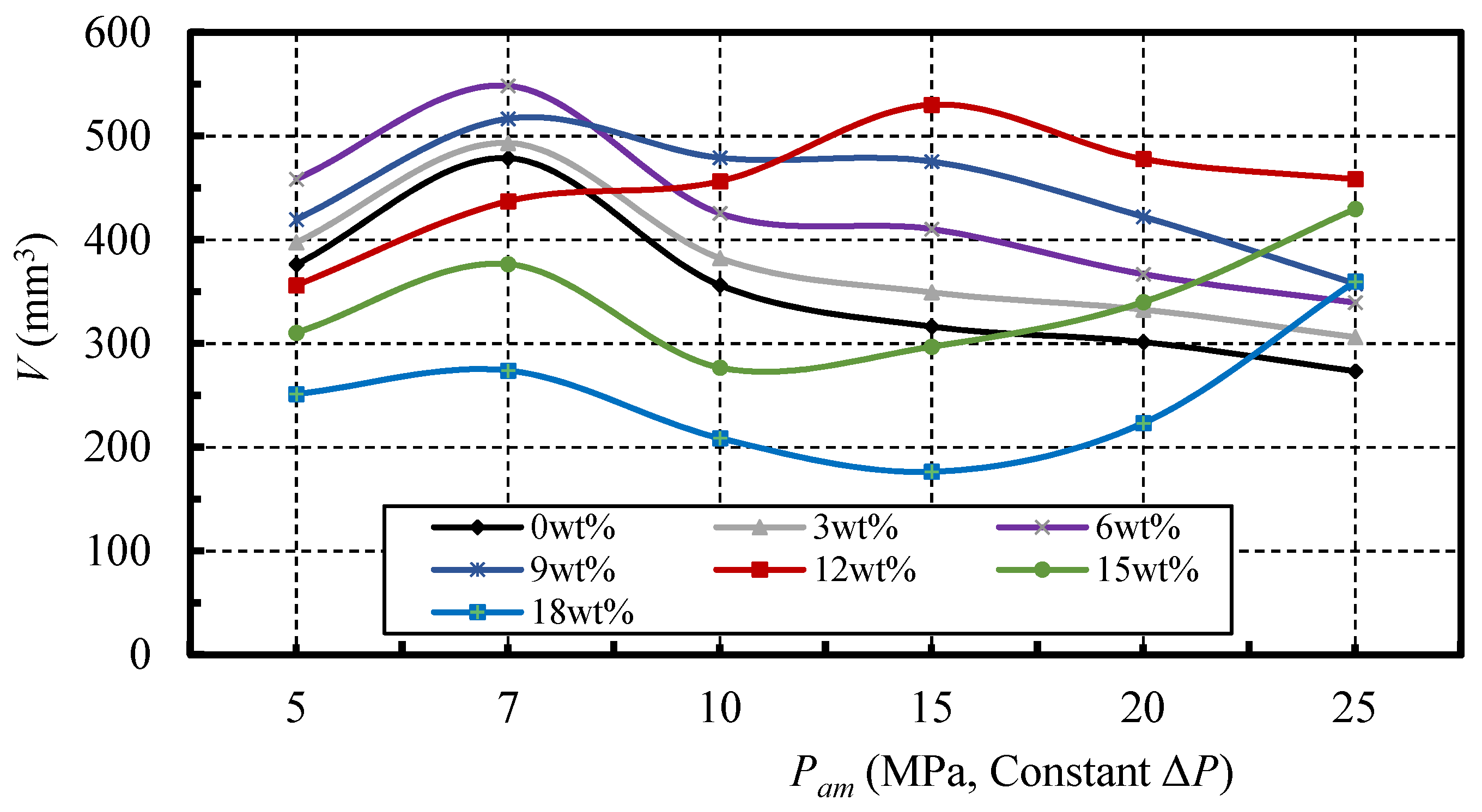
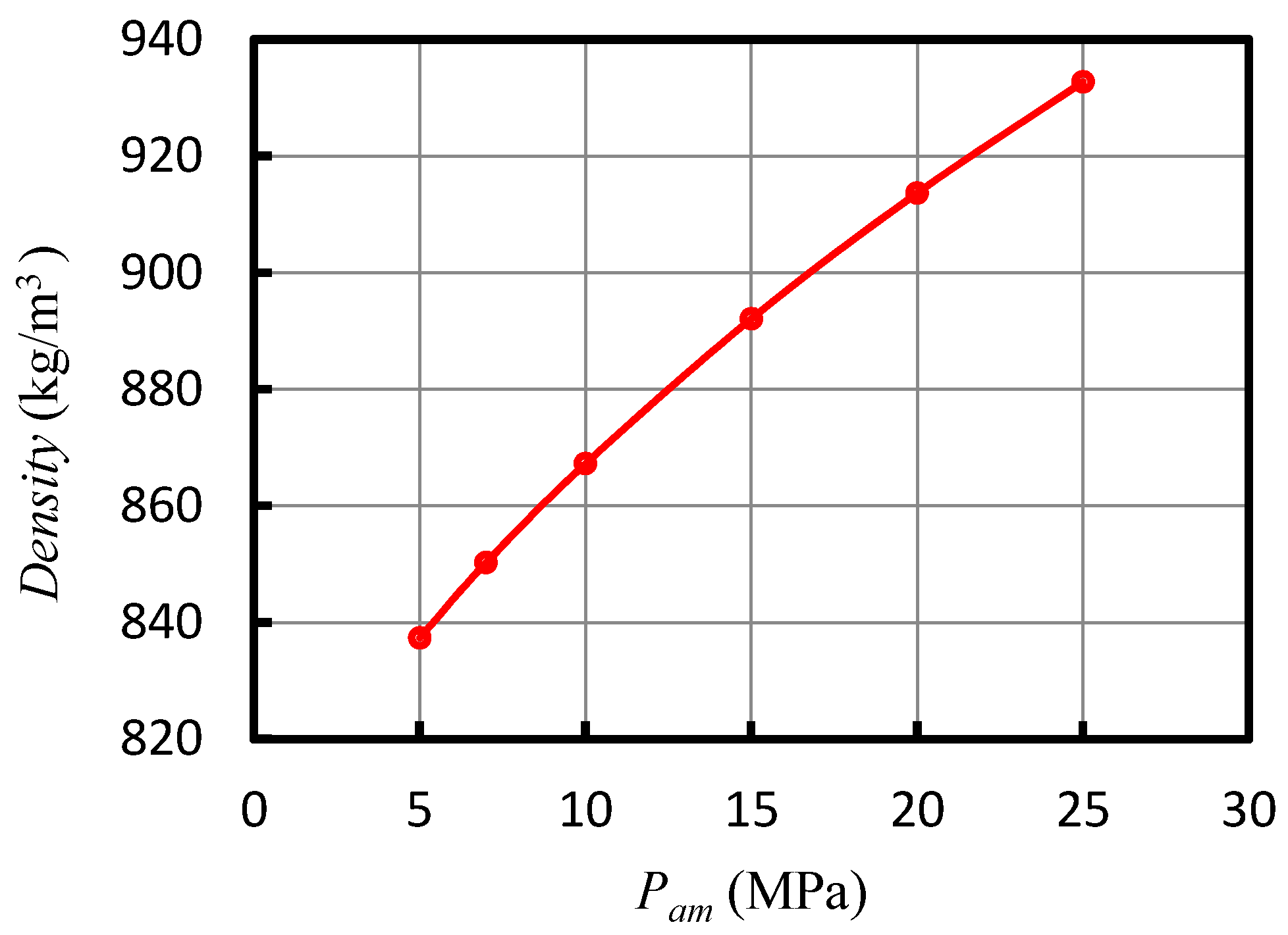
3.5. Effect of Nano-Silica Additive under Different Ambient Pressures And Constant Pressure Drop

Figure 9 shows the influence of ambient pressure on the rock erosion performance of the jets under a constant nozzle pressure drop, ΔP. In this group of experiments, ΔP was set at 30 MPa, the ambient pressure increased from 5 MPa to 25 MPa, and the fluid temperature was set at 340 K. The standoff distances were three and five for the pure and nano-silica SC-CO2 jet, respectively. The mass fractions of the nano-silica additive were 0 wt %, 3 wt %, 6 wt %, 12 wt %, and 18 wt %, respectively.
As is illustrated in the figure, it is obvious that the ambient pressure significantly affects the erosion ability, even though the ΔP value is constant. The curves increase at first and then decrease, for both the pure SC-CO2 jet and nano-silica SC-CO2 jet with a mass fraction of 3 wt %, which is much like that in the rock erosion experiment using the SC-CO2 jet, conducted by Wang et al. [22]. Additionally, the curves of the other nano-silica SC-CO2 jet show some deviations, which seems to be attributed to the erosion effect of the nano-silica particles in the jet flow. Moreover, when the ambient pressure is below the critical pressure of 7.38 MPa, the erosion volumes of all the jets show an increasing trend with the increase of ambient pressure, which is attributed to the increasing diffusivity and reducing viscosity of the CO2 fluid with increasing ambient pressure [27]. Moreover, the erosion ability of the jet with a comparatively low nano-silica mass fraction of 6 wt %, is the largest at ambient pressures of 5 MPa and 7 MPa. Then, with a further increase of the ambient pressure, the mass fraction of 9 wt % becomes the optimal condition, at an ambient pressure of 10 MPa, and the jet with a mass fraction of 12 wt % shows the best erosion performance, when compared to those with an ambient pressure of 15 MPa, 20 MPa, and 25 MPa. In addition, the further increase of ambient pressure can obviously enhance the erosion capabilities of the jets with mass fractions of 15 wt % and 18 wt %. These phenomena indicate that the optimum mass fraction shows an increasing trend with the increase of ambient pressure, under constant ΔP.

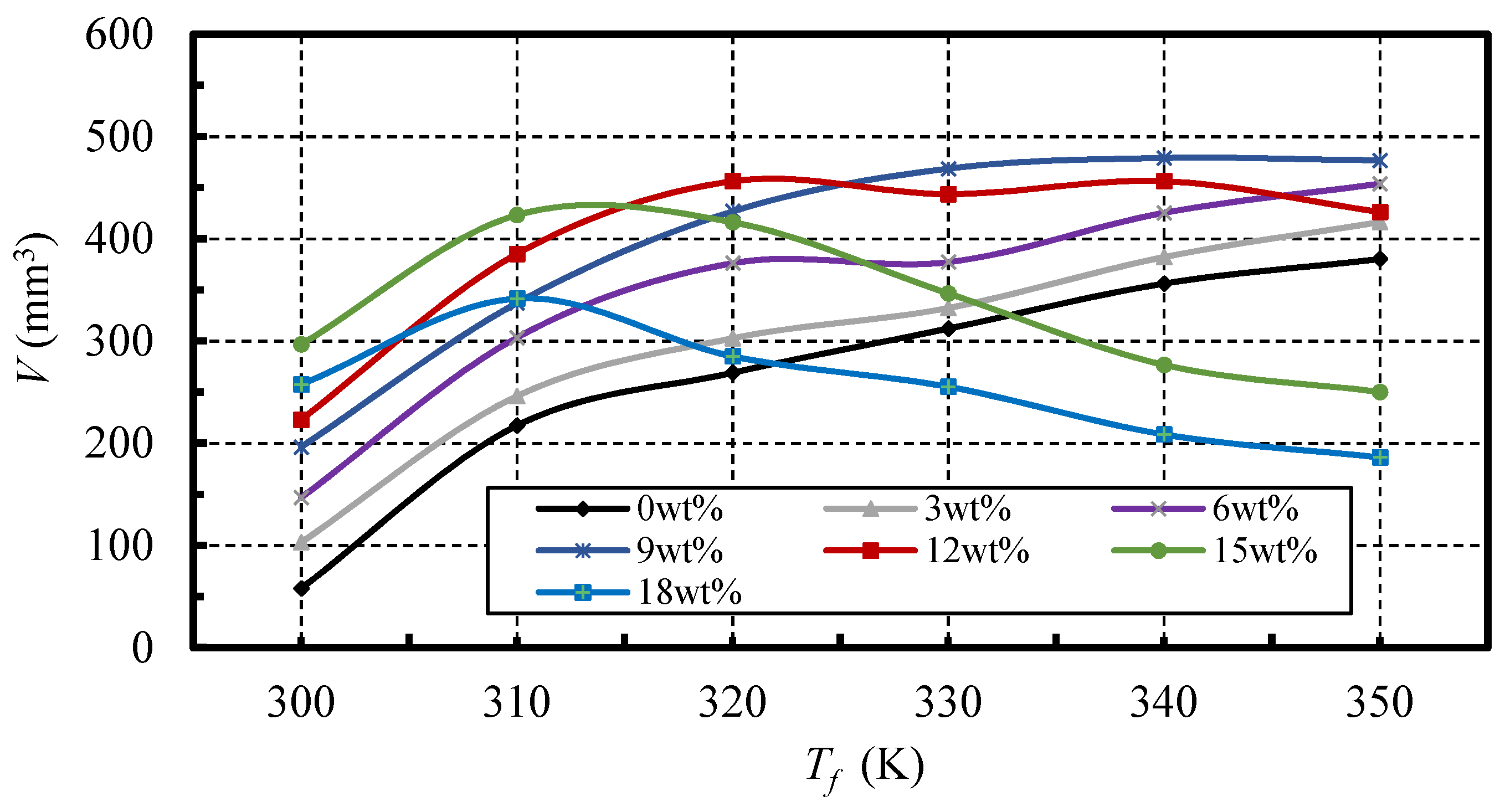
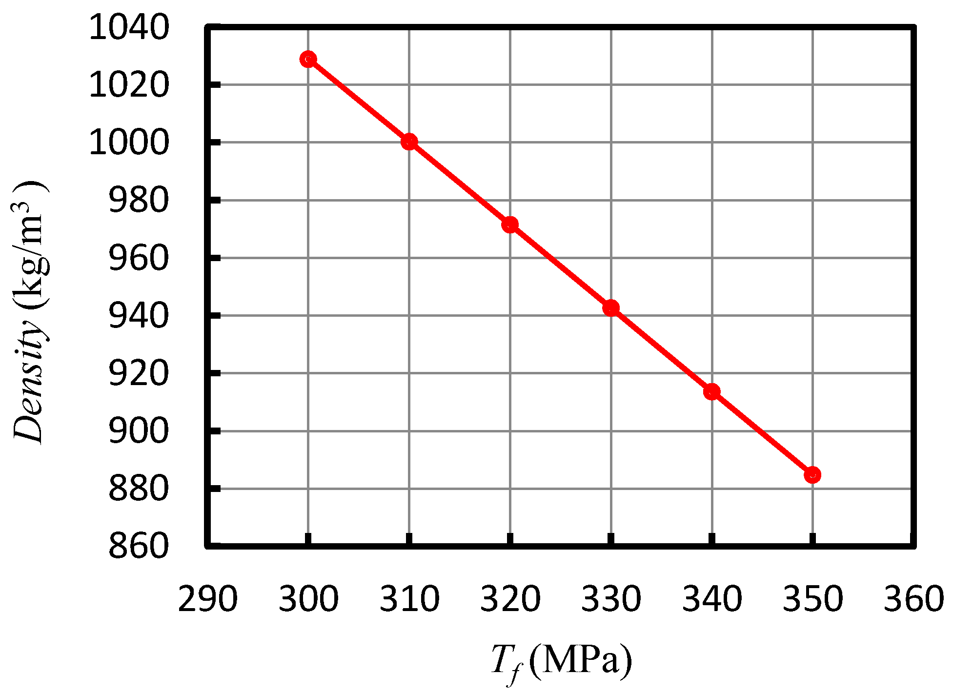
3.6. Effect of the Nano-Silica Additive under Different Fluid Temperatures

Figure 10 shows the effects of fluid temperature on the erosion action of the jets. In this group of experiments, the fluid temperature increased from 300 K to 350 K. The inlet pressure was set at 40 MPa, the ambient pressure was set at 15 MPa, the standoff distances were three and five for the pure and nano-silica CO2 jet, respectively. The mass fractions of the nano-silica additive were 0 wt %, 3 wt %, 6 wt %, 12 wt %, and 18 wt %, respectively.
As can be seen in the figure, it is obvious that the effect of the fluid temperature on the erosion ability of the CO2 jets, largely depends on the nano-silica mass fractions. Specifically, when the fluid temperature increases from the subcritical temperature of 300 K, to the supercritical temperature of 310 K, the erosion capability of all the jets shows an increasing trend with the increase of fluid temperature. This is due to the fact that the diffusivity of the SC-CO2 fluid is significantly higher than that of the liquid CO2, which results in a better erosion effect of the high pressure SC-CO2 fluid, through the permeation in the micro pores [21]. Moreover, at fluid temperatures of 300 K and 310 K, a nano-silica mass fraction of 15 wt % can achieve the largest erosion enhancement. Also, at a fluid temperature of 320 K, the mass fraction of 12 wt % becomes the optimum condition. When the temperature is increased to 330 K, 340 K, and 350 K, the mass fraction of 6 wt % can achieve the largest erosion ability. In addition, above the critical temperature of 304 K, the increase of fluid temperature can reduce the erosion ability of the jet with nano-silica mass fractions of 15 wt % and 18 wt %. These phenomena indicate that the optimum mass fraction has a decreasing trend with the increase of fluid temperature.

4. Discussion

From the experimental results, the nano-silica additive has significant effects on the rock erosion characteristics of the SC-CO2 jet. How the nano-silica additive influences the erosion ability of SC-CO2 jet, is likely to depend on the mass fraction of the nano-silica additive and the operating conditions. This is most likely due to the fact that operating conditions can have large effects on the physical properties of the SC-CO2 fluid [42], which in turn, directly affects the acceleration of the nano-silica particles, as well as the impact characteristics of the nano-silica SC-CO2 jet. In order to further understand the mechanism of the effects of nano-silica on the erosion characteristics of the SC-CO2 jet, a preliminary was performed, as follows.
According to the theory of the erosion of materials by solid particle impact, it is obvious that, when the other conditions are kept constant, the erosion intensity of nano-silica particles on the rock specimens is largely dependent on the impact velocity, which determines the magnitude of the impact loading and the stress wave energy [37]. Moreover, the impact velocity is affected by the forces which participate in the particle motion in the fluid [43]. These forces include interfacial drag, virtual mass, mechanical diffusion, friction, and gravitational forces. Also, the interfacial drag and the virtual mass force are the most important forces that act on the nano-silica particles. The interfacial drag acts in the same direction as the particles accelerate. Furthermore, the direction of the virtual mass force is opposite to the acceleration direction of the particles. The expressions of the forces are as follows [43]:
F d = 3 4 C d ρ f D a ( V f V p ) | V f V p |
F v = 1 2 ρ f V p d ( V f V p ) d x
According to Newton’s second law, the acceleration of the particles can be expressed as:
a = ( F d F v ) m = ρ f [ 3 4 m C d D a ( V f V p ) | V f V p | 1 2 m V p d ( V f V p ) d x ]
As expressed in the equations, the density of the SC-CO2 fluid can have large effects on the acceleration process of the nano-silica particles, and then affects the impact velocity and erosion action of the nano-silica SC-CO2 jet. More specifically, when the other conditions are constant, the increase of fluid density can enhance the acceleration effect of particles in the jet flow.
So, for the experiments on the effect of the inlet pressure on the erosion ability of the nano-silica SC-CO2 jet, the density of the SC-CO2 fluid, calculated by the property routine REFPROP 9.1 [44] at the nozzle inlet, increases with the increase of inlet pressure, as shown in Figure 11. The properties of the SC-CO2 were calculated using the default equations in REFPROP. The increase of density will enhance the acceleration effect of the nano-silica particles in the SC-CO2 fluid, as well as the impingement of the particles on the rock specimens. This can also be verified by the trend of the curves in Figure 7. With the increase of the inlet pressure, the mass fraction of 6 wt % initially has the largest erosion capability. Then, the mass fractions of 9 wt % and 12 wt % take the dominant place, at an inlet pressure between 40 MPa and 55 MPa. Finally, the mass fraction of 15 wt % shows the best erosion performance, at a pressure of 60 MPa. Similarly, for the experiments on the effect of the standoff distance (Figure 6) and the ambient pressure at constant inlet pressure (Figure 8), the density of SC-CO2 fluid at the nozzle inlet is constant. This can be used to explain the phenomenon where the optimum mass fraction of 12 wt % and the mass fraction of 18 wt %, show the weakest erosion capability all of the time, as shown in Figure 6 and Figure 8.
Moreover, for the experiments on the influence of the ambient pressure under constant ΔP, the density of the SC-CO2 fluid at the nozzle inlet increases with increasing ambient pressure, as shown in Figure 12. This results in the increase of the optimum nano-silica mass fraction with increasing ambient pressure, and the obvious enhancement of the erosion ability of the jet with the mass fraction of 18 wt %, at comparatively high ambient pressures of 20 MPa and 25 MPa, as shown in Figure 9.
In addition, for the experiments on the effect of fluid temperature, the density of CO2 fluid decreases with the increase of fluid temperature, as shown in Figure 13. As a result, the optimum nano-silica mass fraction has a decreasing trend with the increase of fluid temperature.
Another interesting phenomenon that can be observed in Figure 6, Figure 7, Figure 8, Figure 9 and Figure 10, is that the nano-silica additive can cause a reduction in the erosion capability of the SC-CO2 jet, under certain conditions. For instance, the erosion ability of the jet with a nano-silica mass fraction of 18 wt % is worse than that of the pure SC-CO2 jet at inlet pressures below 50 Mpa, as shown in Figure 7. This is likely to be due to the existence of competition between the erosion enhancement and the additional energy dissipation. To be more specific, the viscosity of the fluid can be increased by the nano-silica additive [45]. So, excessive mass fractions of the nano-silica additive will raise the viscous dissipation of the energy of the high speed turbulent SC-CO2 jet flow, thus resulting in the reduction of the erosion capability. On the other hand, impingement of the nano-silica particles, accelerated by the high speed SC-CO2 jet fluid, can enhance the rock erosion ability, and the better the acceleration effect is, the greater the enhancement is. Therefore, if the enhancement of the erosion caused by the impingement of nano-silica particles, is stronger than that of the energy dissipation, the erosion capability of the SC-CO2 jet will be improved by the nano-silica additive; if not, energy dissipation will be the dominated effect, resulting in a reduction of the erosion ability. This hypothesis can be used to explain the experimental phenomena where the acceleration effect is poor with a low density of SC-CO2 fluid, and the high mass fraction of the nano-silica additive tends to cause a negative effect on the erosion ability.
Finally, it is well known that the nozzle design, including structural parameters and nozzle types, can strongly affect the characteristics of the SC-CO2 jet, such as the focussing of the jet, Mach shock, jet collimation etc. Furthermore, it greatly affects the rock erosion behaviors of the SC-CO2 jet. Therefore, the impact of the nozzle design on the rock erosion characteristics of the SC-CO2 jet will be emphatically studied in the near future.

5. Conclusions

In pursuit of improving the rock erosion ability of the SC-CO2 jet, for better practical utilizations, experiments were conducted to investigate the effect of a nano-silica additive on the rock erosion characteristics, with a rock erosion test system of the SC-CO2 jet. The erosion capability was evaluated by the erosion volume on rock specimens. Some essential conclusions can be drawn as follows:
  • The erosion of the rock specimen caused by the impingement of the SC-CO2 jet, is the typical “drilling type” damage characterized by rather deep cavities with small diameters.
  • The optimal standoff distances are about five times the nozzle diameter of the nano-silica SC-CO2 jets, and three times those of the pure SC-CO2 jet. After the standoff distance exceeds the optimum value, the erosion ability of all the jets greatly decreases.
  • The erosion abilities of all the jets show an increasing trend with the increase of inlet pressure. At the inlet pressures of 30 MPa and 35 MPa, a mass fraction of 6 wt % can achieve a better erosion ability than the others, while at an inlet pressure of 40 MPa, 9 wt % is the optimum mass fraction. Also, at inlet pressures of 45 MPa and 50 MPa, a mass fraction of 12 wt % is the optimum condition. In addition, when the inlet pressure is increased to 60 MPa, the jet with a mass fraction of 15 wt % has the best erosion ability.
  • Under a constant inlet pressure, the rock erosion ability of all the jets decreases with the increasing ambient pressure. Also, the optimum mass fraction is 12 wt %.
  • Under the constant ΔP, the SC-CO2 jet with a nano-silica mass fraction of 6 wt % has the best erosion ability at ambient pressures of 5 MPa and 7 MPa. Then, with the increase of ambient pressure, mass fractions of 9 wt % and 12 wt %, take turns to achieve the best erosion ability. Moreover, a further increase of ambient pressure can enhance the erosion capability of the jets with mass fractions of 15 wt % and 18 wt %.
  • At fluid temperatures of 300 K and 310 K, a mass fraction of 15 wt % can achieve the strongest erosion ability. Additionally, at a fluid temperature of 320 K, a mass fraction of 12 wt % becomes the optimum condition. In addition, at fluid temperatures above 330 K, the mass fraction of 6 wt % is the most appropriate choice.

Acknowledgments

The authors express their appreciations to National Key Basic Research Program of China (No. 2014CB239203), National Natural Science Foundation of China (No. 51474158), and Program for New Century Excellent Talents in University of Ministry of Education (Grant No. NCET-12-0424) for the financial support of this work.

Author Contributions

Man Huang, Yong Kang, and Xinping Long conceived and designed the facilities and the experiments; Man Huang, Yi Hu and Mingxing Zhang performed the experiments; Xiaochuan Wang and Deng Li analyzed the data and made the analysis; Man Huang wrote the paper.

Conflicts of Interest

The authors declare no conflict of interest.

Nomenclatures

d0nozzle exit diameter, mm
αnozzle convergent angle,
l1length of the cylinder section of the nozzle, mm
l2length of the conical section of the nozzle, mm
Pinnozzle inlet pressure, MPa
Pamambient pressure, MPa
Tffluid temperature, K
ΔPpressure drop across the nozzle
Verosion volume, mm3
Sstandoff distance, mm
Vpparticle velocity, m/s
Vffluid velocity, m/s
ρffluid densiy, kg/m3
ρsdensity of salt, kg/m3
Fddrag force, N
Fvvirtual mass force, N
Cdinterfacial drag coefficient
Dadiameter of particle, mm
mmass of particle, kg
m1, m2mass of salt, kg
aacceleration of particle, m/s2

References

  1. Bellan, J. Supercritical (and subcritical) fluid behavior and modeling: Drops, streams, shear and mixing layers, jets and sprays. Prog. Energ. Combust. 2000, 26, 329–366. [Google Scholar] [CrossRef]
  2. Brunner, G. Applications of supercritical fluids. Annu. Rev. Chem. Biomol. 2010, 1, 321–342. [Google Scholar] [CrossRef] [PubMed]
  3. Vatai, T.; Škerget, M.; Knez, Ž. Extraction of phenolic compounds from elder berry and different grape marc varieties using organic solvents and/or supercritical carbon dioxide. J. Food. Eng. 2009, 90, 246–254. [Google Scholar] [CrossRef]
  4. Zhang, X.R.; Yamaguchi, H.; Uneno, D.; Fujima, K.; Enomoto, M.; Sawada, N. Analysis of a novel solar energy-powered rankine cycle for combined power and heat generation using supercritical carbon dioxide. Renew. Energy 2006, 31, 1839–1854. [Google Scholar] [CrossRef]
  5. Aroso, I.M.; Duarte, A.R.C.; Pires, R.R.; Mano, J.F.; Reis, R.L. Cork processing with supercritical carbon dioxide: Impregnation and sorption studies. J. Supercrit. Fluids 2015, 104, 251–258. [Google Scholar] [CrossRef]
  6. Knez, Ž.; Markočič, E.; Leitgeb, M.; Primožič, M.; Knez Hrnčič, M.; Škerget, M. Industrial applications of supercritical fluids: A review. Energy 2014, 77, 235–243. [Google Scholar] [CrossRef]
  7. Gupta, A.P.; Gupta, A.; Langlinais, J. Feasibility of supercritical carbon dioxide as a drilling fluid for deep underbalanced drilling operation. In Proceedings of the SPE Annual Technical Conference and Exhibition, Dallas, TX, USA, 9–12 October 2005.
  8. ALAdwani, F.A. Mechanistic Modeling of an Underbalanced Drilling Operation Utilizing Supercritical Carbon Dioxide. Ph.D. Thesis, Louisiana State University, Baton Rouge, LA, USA, August 2007. [Google Scholar]
  9. Shen, Z.; Wang, H.; Li, G. Feasibility analysis of coiled tubing drilling with supercritical carbon dioxide. Pet. Explor. Dev. 2010, 37, 743–747. [Google Scholar] [CrossRef]
  10. Middleton, R.S.; Carey, J.W.; Currier, R.P.; Hyman, J.D.; Kang, Q.; Karra, S.; Jiménez-Martínez, J.; Porter, M.L.; Viswanathan, H.S. Shale gas and non-aqueous fracturing fluids: Opportunities and challenges for supercritical CO2. Appl. Energy 2015, 147, 500–509. [Google Scholar] [CrossRef]
  11. Wang, H.; Li, G.; Shen, Z. A feasibility analysis on shale gas exploitation with supercritical carbon dioxide. Energy Source A 2012, 34, 1426–1435. [Google Scholar] [CrossRef]
  12. Lyu, Q.; Long, X.P.; Ranjith, P.G.; Kang, Y. Unconventional gas: Experimental study of the influence of subcritical carbon dioxide on the mechanical properties of black shale. Energies 2016, 9. [Google Scholar] [CrossRef]
  13. He, Z.; Tian, S.; Li, G.; Wang, H.; Shen, Z.; Xu, Z. The pressurization effect of jet fracturing using supercritical carbon dioxide. J. Nat. Gas Sci. Eng. 2015, 27, 842–851. [Google Scholar] [CrossRef]
  14. Zhang, X.; Lu, Y.; Tang, J.; Zhou, Z.; Liao, Y. Experimental study on fracture initiation and propagation in shale using supercritical carbon dioxide fracturing. Fuel 2017, 190, 370–378. [Google Scholar] [CrossRef]
  15. Merey, S.; Sinayuc, C. Analysis of carbon dioxide sequestration in shale gas reservoirs by using experimental adsorption data and adsorption models. J. Nat. Gas Sci. Eng. 2016, 36, 1087–1105. [Google Scholar] [CrossRef]
  16. Reznik, A.A.; Singh, P.K.; Foley, W.L. An analysis of the effect of CO2 injection on the recovery of insitu methane from bituminous coal—An experimental simulation. Soc. Pet. Eng. J. 1984, 24, 521–528. [Google Scholar] [CrossRef]
  17. Song, W.Q.; Wang, R.H.; Ni, H.J.; Huo, H.J.; Shen, Z.H. Multiphase flow mechanism of sand cleanout with supercritical carbon dioxide in a deviated wellbore. J. Nat. Gas Sci. Eng. 2015, 25, 140–147. [Google Scholar] [CrossRef]
  18. Sun, X.; Ni, H.J.; Qiao, H.S.; Wang, X.Y.; Ma, B.; Wang, R.H.; Shen, Z.H.; Zhao, M.Y. Experimental study on the mechanism of carbon dioxide removing formation paraffin deposits. J. Nat. Gas Sci. Eng. 2016, 32, 59–65. [Google Scholar] [CrossRef]
  19. Zhou, J.; Liu, G.; Jiang, Y.; Xian, X.; Liu, Q.; Zhang, D.; Tan, J. Supercritical carbon dioxide fracturing in shale and the coupled effects on the permeability of fractured shale: An experimental study. J. Nat. Gas Sci. Eng. 2016, 36, 369–377. [Google Scholar] [CrossRef]
  20. Kolle, J.J. Coiled-tubing drilling with supercritical carbon dioxide. In Proceedings of the SPE/CIM International Conference on Horizontal Well Technology, Calgary, AB, Canada, 6–8 November 2000.
  21. Du, Y.K.; Wang, R.H.; Ni, H.J.; Li, M.K.; Song, W.Q.; Song, H.F. Determination of rock-breaking performance of high-pressure supercritical carbon dioxide jet. J. Hydrodyn. 2012, 24, 554–560. [Google Scholar] [CrossRef]
  22. Wang, H.Z.; Li, G.S.; Shen, Z.H.; Tian, S.C.; Sun, B.J.; He, Z.G.; Lu, P.Q. Experiment on rock breaking with supercritical carbon dioxide jet. J. Pet. Sci. Eng. 2015, 127, 305–310. [Google Scholar] [CrossRef]
  23. He, Z.; Li, G.; Tian, S.; Wang, H.; Shen, Z.; Li, J. SEM analysis on rock failure mechanism by supercritical CO2 jet impingement. J. Pet. Sci. Eng. 2016, 146, 111–120. [Google Scholar] [CrossRef]
  24. Wang, H.Z.; Li, G.S.; Tian, S.C.; Cheng, Y.X.; He, Z.G.; Yu, S.J. Flow field simulation of supercritical carbon dioxide jet: Comparison and sensitivity analysis. J. Hydrodyn. 2015, 27, 210–215. [Google Scholar] [CrossRef]
  25. Long, X.; Liu, Q.; Ruan, X.; Kang, Y.; Lyu, Q. Numerical investigation of the flow of supercritical carbon dioxide injected into the bottom hole during drilling with special emphasis on the real gas effects. J. Nat. Gas. Sci. Eng. 2016, 34, 1044–1053. [Google Scholar] [CrossRef]
  26. Wang, R.H.; Huo, H.J.; Huang, Z.Y.; Song, H.F.; Ni, H.J. Experimental and numerical simulations of bottom hole temperature and pressure distributions of supercritical CO2 jet for well-drilling. J. Hydrodyn. 2014, 26, 226–233. [Google Scholar] [CrossRef]
  27. Tian, S.C.; He, Z.G.; Li, G.S.; Wang, H.Z.; Shen, Z.H.; Liu, Q.L. Influences of ambient pressure and nozzle-to-target distance on SC-CO2 jet impingement and perforation. J. Nat. Gas Sci. Eng. 2016, 29, 232–242. [Google Scholar] [CrossRef]
  28. Annoni, M.M.; Bertola, V.; Goletti, M. The role of polymeric additives in water jet cutting. Int. J. Mach. Mach. Mater. 2009, 6. [Google Scholar] [CrossRef]
  29. Hu, D.; Tang, C.L.; Kang, Y.; Li, X.Y. An investigation on cutting quality by adding polymer in abrasive water jet. Part. Sci. Technol. 2016, 34, 352–358. [Google Scholar] [CrossRef]
  30. Mao, H.; Qiu, Z.S.; Shen, Z.H.; Huang, W.A.; Zhong, H.Y.; Dai, W.H. Novel hydrophobic associated polymer based nano-silica composite with core-shell structure for intelligent drilling fluid under ultra-high temperature and ultra-high pressure. Prog. Nat. Sci. Mater. 2015, 25, 90–93. [Google Scholar] [CrossRef]
  31. Li, G.; Zhang, J.; Zhao, h.; Hou, Y. Nanotechnology to improve sealing ability of drilling fluids for shale with micro-cracks during drilling. In Proceedings of the SPE International Oilfield Nanotechnology Conference and Exhibition, Noordwijk, The Netherlands, 12–14 June 2012.
  32. Hoelscher, K.P.; De Stefano, G.; Riley, M.; Young, S. Application of nanotechnology in drilling fluids. In Proceedings of the SPE International Oilfield Nanotechnology Conference and Exhibition, Noordwijk, The Netherlands, 12–14 June 2012.
  33. Huang, T.; Crews, J.B.; Agrawal, G. Nanoparticle pseudocrosslinked micellar fluids: Optimal solution for fluid-loss control with internal breaking. In Proceedings of the SPE International Oilfield Nanotechnology Conference and Exhibition, Noordwijk, The Netherlands, 12–14 June 2012.
  34. Li, Y.Z.; DiCarlo, D.; Li, X.F.; Zang, J.L.; Li, Z.N. An experimental study on application of nanoparticles in unconventional gas reservoir CO2 fracturing. J. Pet. Sci. Eng. 2015, 133, 238–244. [Google Scholar] [CrossRef]
  35. Gnirk, P.F.; Grams, W.H. Rock Drilling with Pulsed High-Velocity Water Jets; American Rock Mechanics Association: Alexandria, VA, USA, 1972. [Google Scholar]
  36. Daniel, I.M. Experimental studies of water jet impact on rock and rocklike materials. In Proceedings of the 3rd International Symposium on Jet Cutting Technology, Chicago, IL, USA, 11–13 May 1976; pp. 27–46.
  37. Zeng, J.; Kim, T.J. An erosion model of polycrystalline ceramics in abrasive waterjet cutting. Wear 1996, 193, 207–217. [Google Scholar]
  38. Momber, A.W. Deformation and fracture of rocks due to high-speed liquid impingement. Int. J. Fract. 2004, 130, 683–704. [Google Scholar] [CrossRef]
  39. Zuo, W.Q. Abrasive Accelerated Mechanisms and Distribution Law in Pre-Mixed Abrasive Jet. Ph.D. Thesis, Chongqing University, Chongqing, China, February 2012. [Google Scholar]
  40. Woolley, R.M.; Fairweather, M.; Wareing, C.J.; Falle, S.A.E.G.; Proust, C.; Hebrard, J.; Jamois, D. Experimental measurement and Reynolds-averaged Navier–Stokes modelling of the near-field structure of multi-phase CO2 jet releases. Int. J. Greenh. Gas Control 2013, 18, 139–149. [Google Scholar] [CrossRef] [Green Version]
  41. Woolley, R.M.; Fairweather, M.; Wareing, C.J.; Falle, S.A.E.G.; Mahgerefteh, H.; Martynov, S.; Brown, S.; Narasimhamurthy, V.D.; Storvik, I.E.; Sælen, L.; et al. CO2 PipeHaz: Quantitative hazard assessment for next generation CO2 pipelines. Energy Procedia 2014, 63, 2510–2529. [Google Scholar] [CrossRef]
  42. Lv, Q.; Long, X.P.; Kang, Y.; Xiao, L.Z.; Wu, W. Numerical investigation on the expansion of supercritical carbon dioxide jet. IOP Conf. Ser. Matesr. Sci. Eng. 2013, 52, 072011. [Google Scholar] [CrossRef]
  43. Tazibt, A.; Parsy, F.; Abriak, N. Theoretical analysis of the particle acceleration process in abrasive water jet cutting. Comp. Mater. Sci. 1996, 5, 243–254. [Google Scholar] [CrossRef]
  44. Lemmon, E.W.; Huber, M.L.; McLinden, M.O. Refprop; 9.1; National Institute of Standards and Technology (NIST): Gaithersburg, MD, USA, 2016. [Google Scholar]
  45. Mao, H.; Qiu, Z.S.; Shen, Z.H.; Huang, W.A. Hydrophobic associated polymer based silica nanoparticles composite with core-shell structure as a filtrate reducer for drilling fluid at utra-high temperature. J. Pet. Sci. Eng. 2015, 129, 1–14. [Google Scholar] [CrossRef]
Figure 1. Schematic of coiled-tubing drilling technology using a SC-CO2 jet [20].
Applsci 07 00153 g001
Figure 2. Schematic diagram of the rock erosion test system of a SC-CO2 jet.
Applsci 07 00153 g002
Figure 3. Schematic diagram of the convergent nozzle.
Applsci 07 00153 g003
Figure 4. Schematic diagram of the measurement of the erosion volume.
Applsci 07 00153 g004
Figure 5. Photos of rock specimens after erosion: top ones for the nano-silica SC-CO2 jet with a mass fraction of 12 wt %, bottom ones for the pure SC-CO2 jet, Pin = 50 MPa, Pam = 15 MPa, Tf = 340 K.
Applsci 07 00153 g005
Figure 6. Effect of standoff distance on rock erosion capability of the SC-CO2 jet.
Applsci 07 00153 g006
Figure 7. Rock erosion characteristics under various nozzle inlet pressures.
Applsci 07 00153 g007
Figure 8. Rock erosion characteristics under various ambient pressures and a constant inlet pressure.
Applsci 07 00153 g008
Figure 9. Rock erosion characteristics under various ambient pressures and constant ΔP.
Applsci 07 00153 g009
Figure 10. Rock erosion characteristics under various fluid temperatures.
Applsci 07 00153 g010
Figure 11. The density of SC-CO2 fluid versus nozzle inlet pressure (Data from REFPROP).
Applsci 07 00153 g011
Figure 12. The density of SC-CO2 fluid versus ambient pressure under constant ΔP (Data from REFPROP).
Applsci 07 00153 g012
Figure 13. The density of SC-CO2 fluid versus fluid temperature (Data from REFPROP).
Applsci 07 00153 g013
Table 1. Properties of nano-silica.
Specific Surface Area (m2/g)Purity (%)Density (g/cm3)Particle Size (nm)
200 ± 20≥99.81.8~2.130 ± 5
Table 2. Physical and mechanical properties of the rock specimens.
NumberLength (mm)Diameter (mm)Density (g/cm3)Compressive Strength (MPa)Modulus of Elasticity (GPa)Poisson’s Ratios
198.5502.638.28.380.12
2100.5502.538.58.320.11
399.3502.537.98.350.12

