
Performance Evaluation of Waterproofing Membrane Systems Subject to the Concrete Joint Load Behavior of Below-Grade Concrete Structures


Abstract
:1. Introduction
2. Below-Grade Waterproofing Membrane Systems
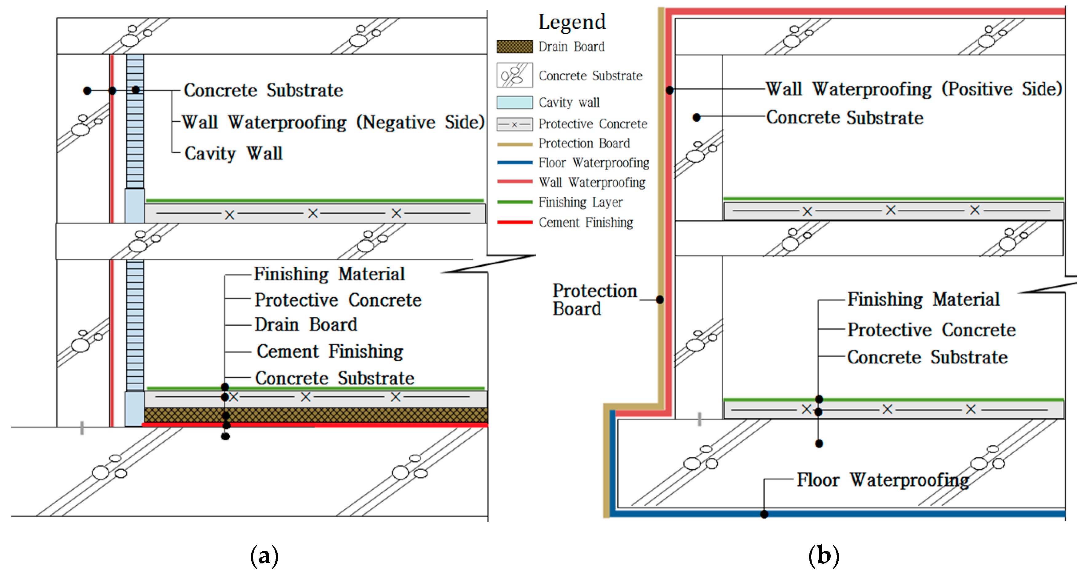
2.1. Below-Grade Concrete Structure Waterproofing Methods
2.2. Selected Waterproofing Membrane Systems for Evaluation
3. Loading Modes and Exposure Conditions
3.1. Effects of Zero-Span Tensile Stress, Displacement Range, and Speed of Concrete Joint on Waterproofing Membrane
3.1.1. Zero-Span Tensile Stress
3.1.2. Joint Displacement Range, Speed, and Cycle
3.2. Workmanship and Adhesion Property of Waterproofing Sheet Membrane Overlap Joint
3.3. Adhesion on Wet Concrete Substrate and Waterproofing Membrane
3.4. Existing Evaluation Methods for Waterproofing Membrane Systems
3.5. New Proposed Evaluation Method and Criteria
4. Test Method and Apparatus
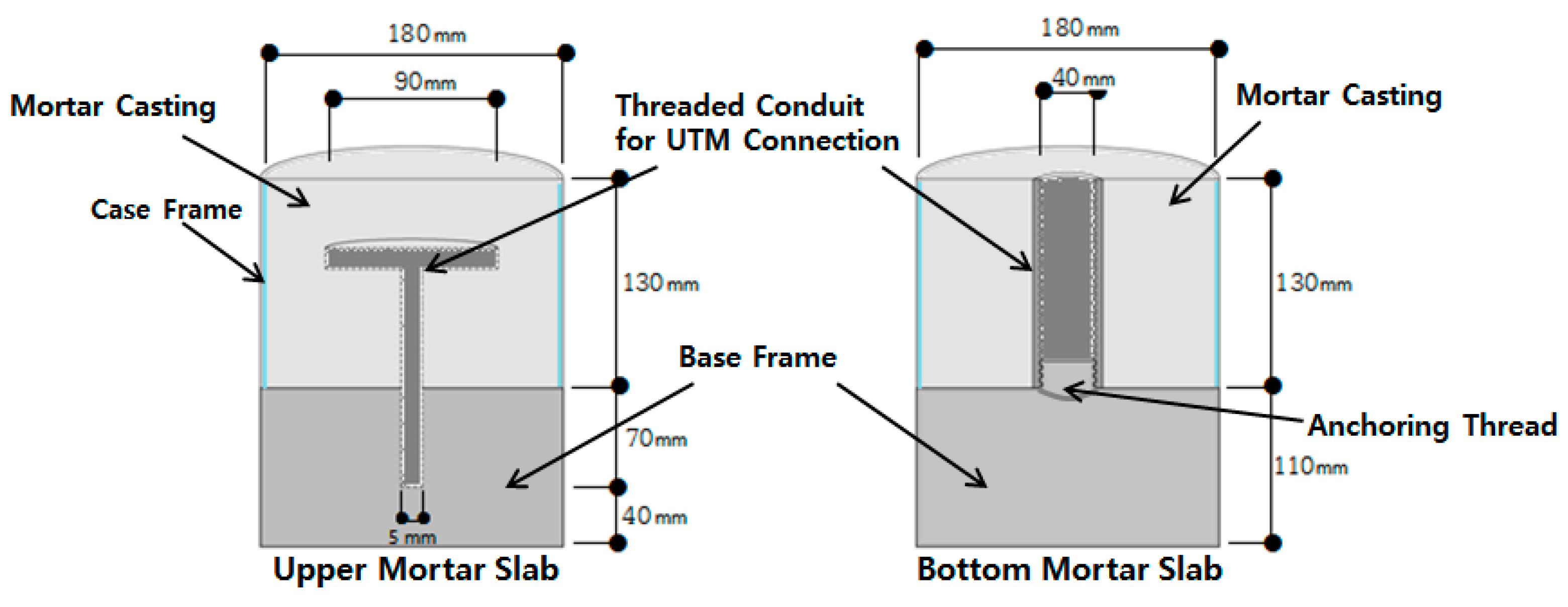
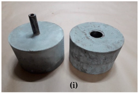
4.1. Mold Assembly
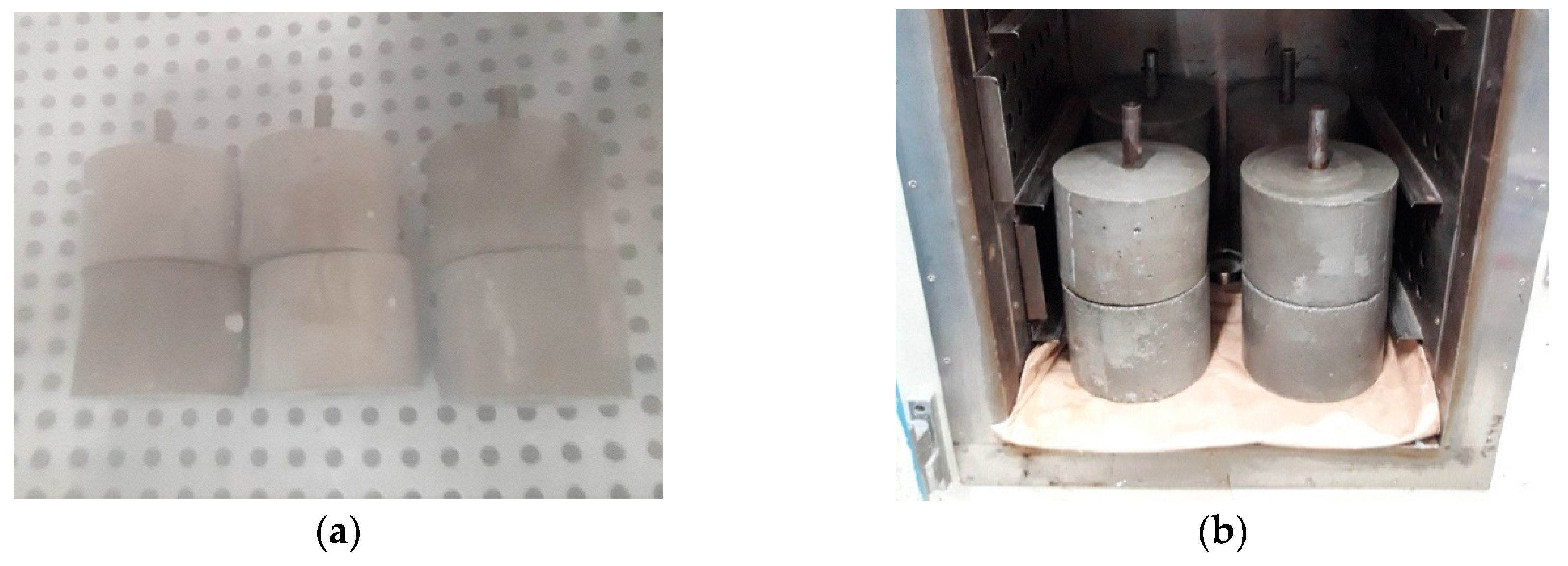
4.2. Mortar Slab Casting and Curing
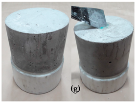
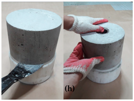
4.3. Mortar Slab Demolding
4.4. Conditioning of Mortar Slab
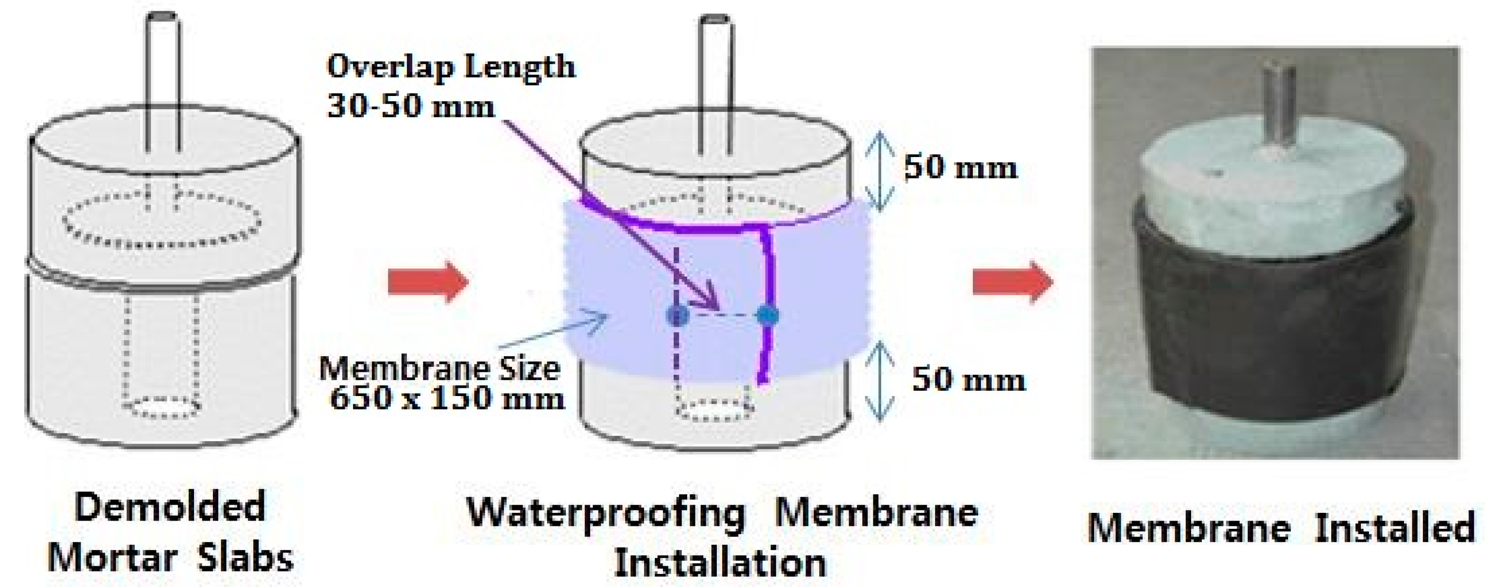
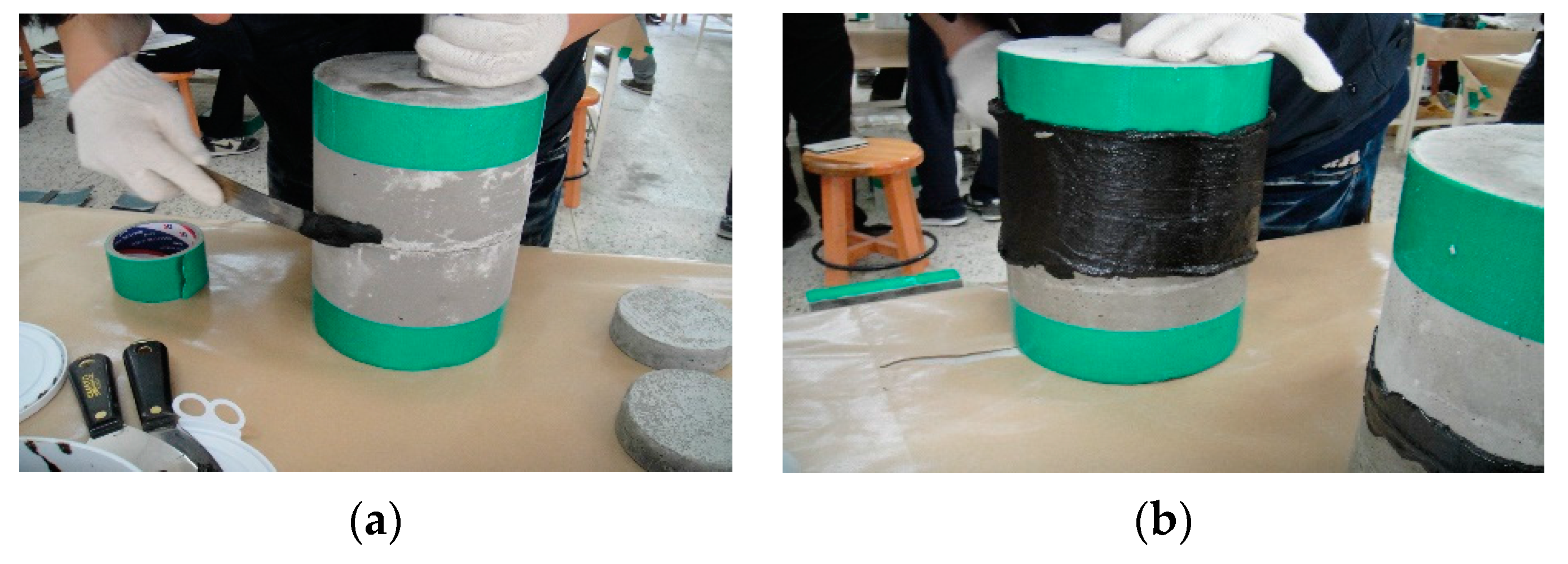
4.5. Installation of Waterproofing Membrane on Mortar Slabs
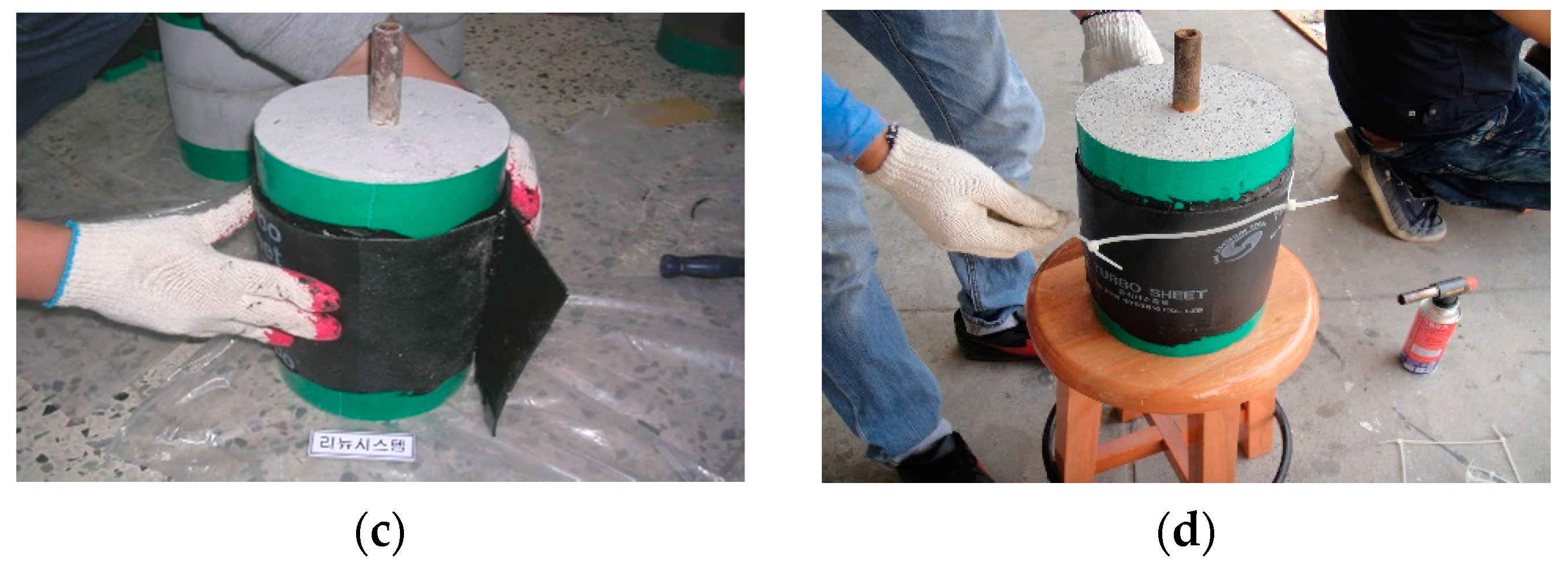
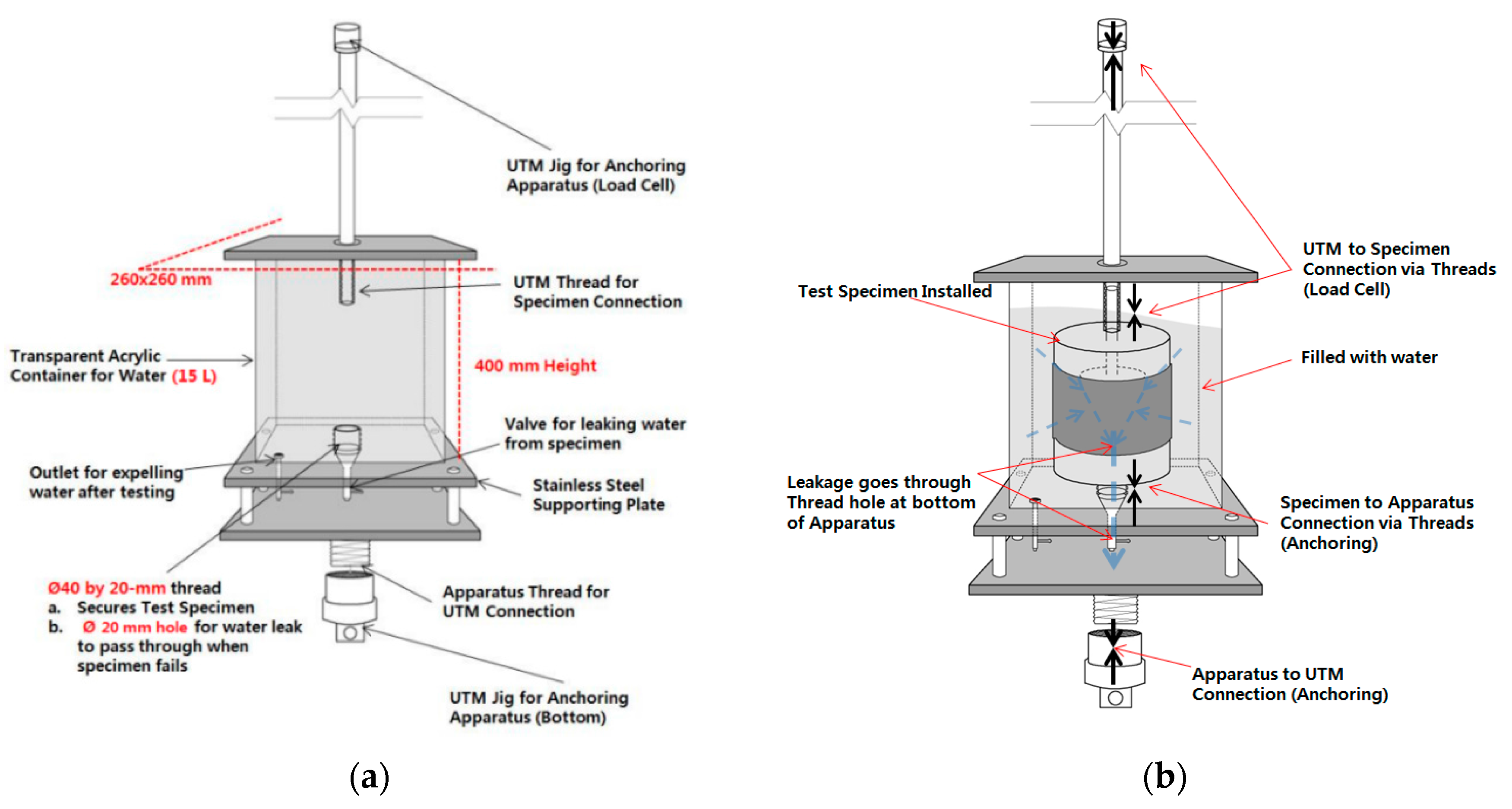
4.6. Testing Apparatus Design and Setting for Joint Displacement Testing
- (1)
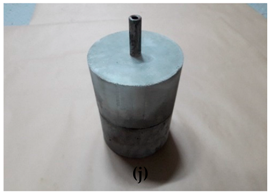
- The test specimen is installed into the acrylic chamber apparatus by screwing the threaded conduit of the bottom mortar slab onto the metallic thread at the bottom of the chamber.
- (2)
- The container is filled with approximately 15 L of water. The specimen should be completely submerged in water.
- (3)
- The chamber is installed onto the UTM. The bottom connection is anchored with a rivet to the jig of the UTM. The upper mortar slab threaded conduit is then anchored to the upper jig of the UTM.
- (4)
- The joint displacement speed (construction joint movement rate) is set to 50 mm/min.
- (5)
- The test is initiated in the conditions outlined in Table 7.
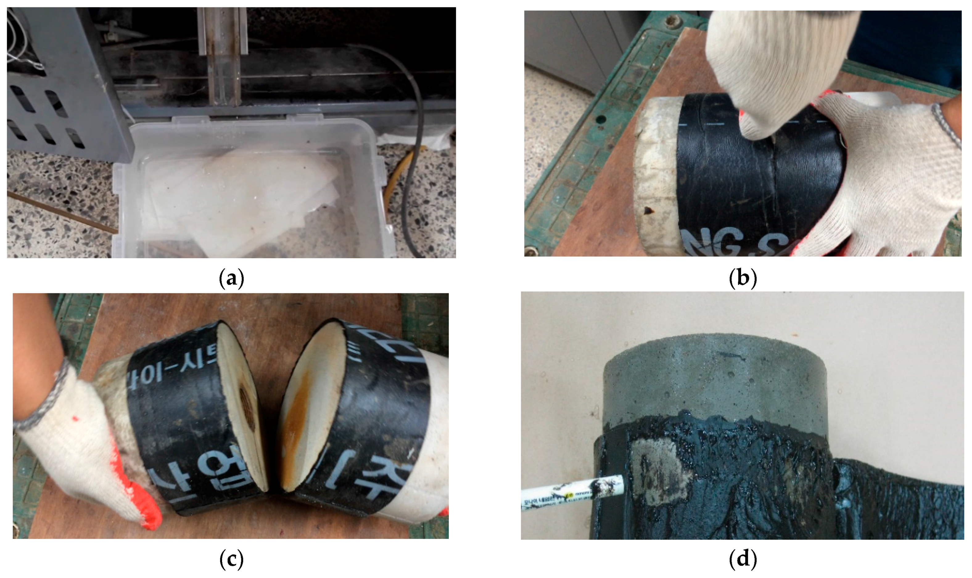
4.7. Failure Type Analysis Method of Tested Waterproofing Membrane
5. Evaluation of Six Waterproofing Membranes Using the Proposed Testing Method
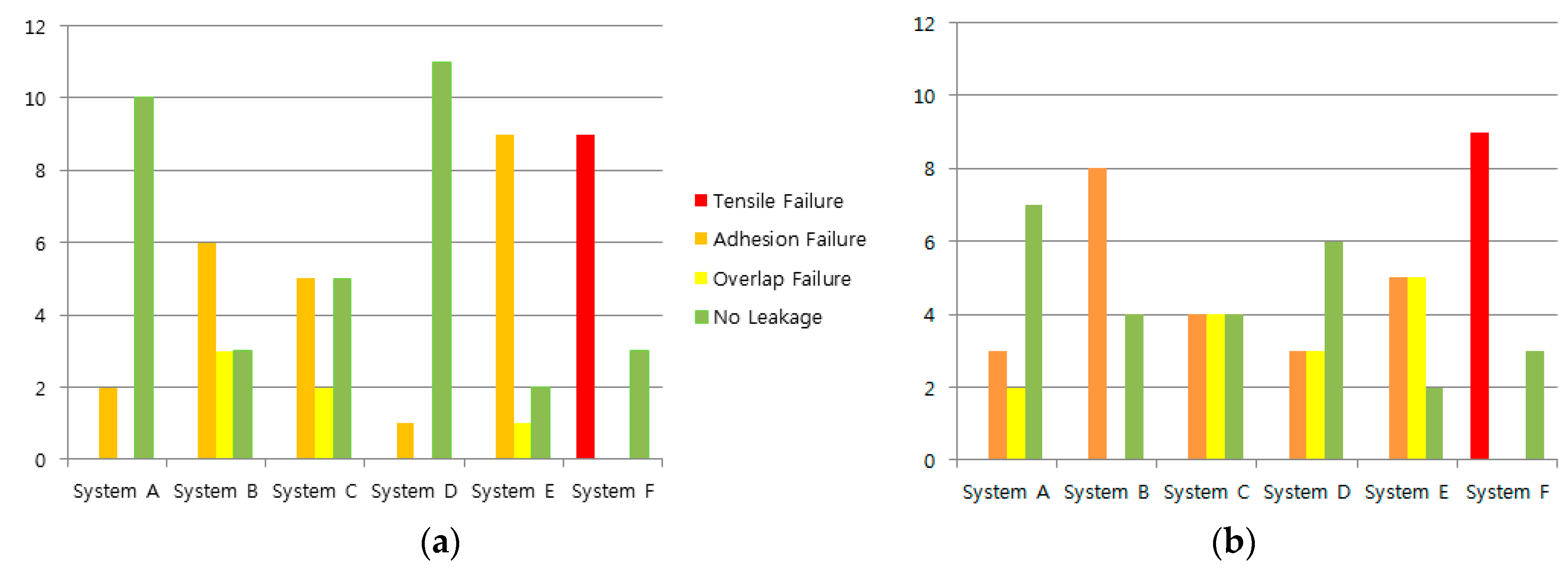
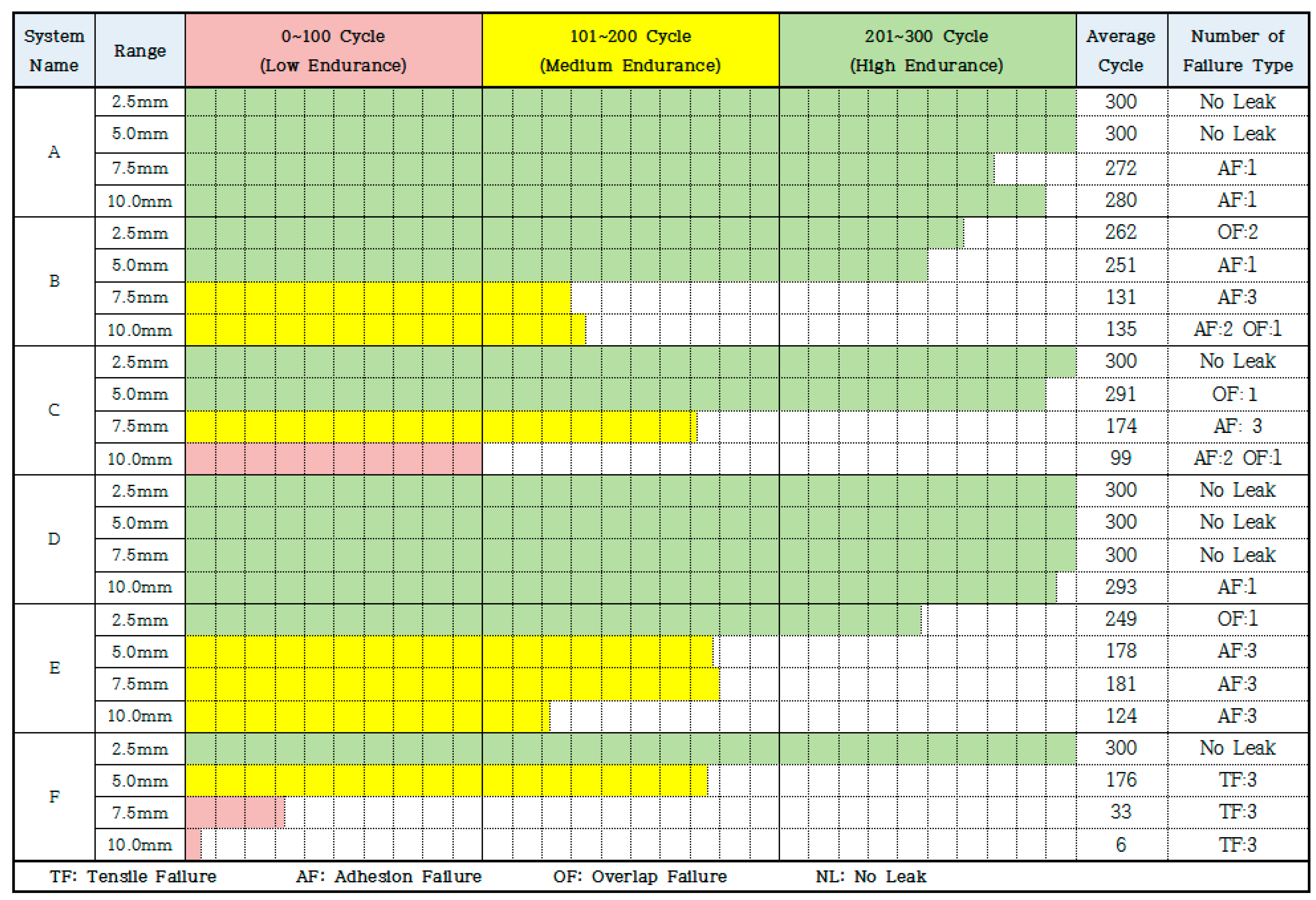
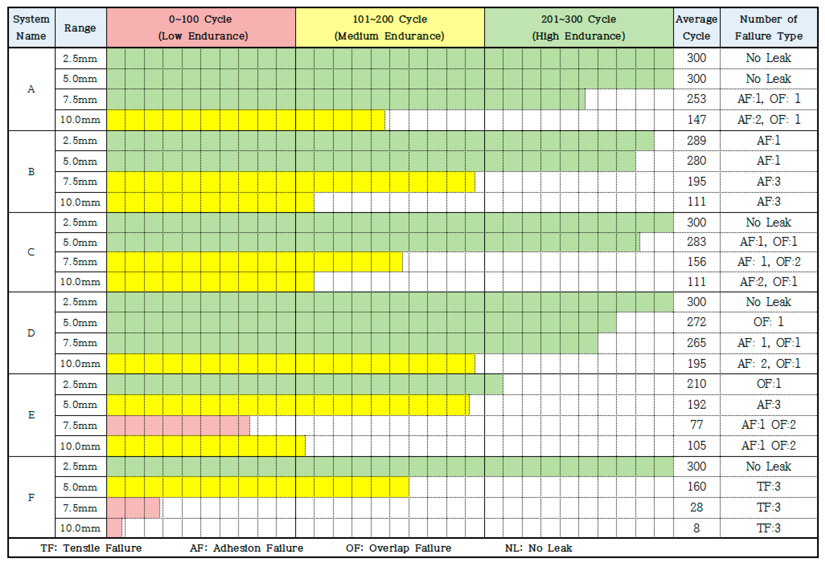
5.1. Evaluation Results
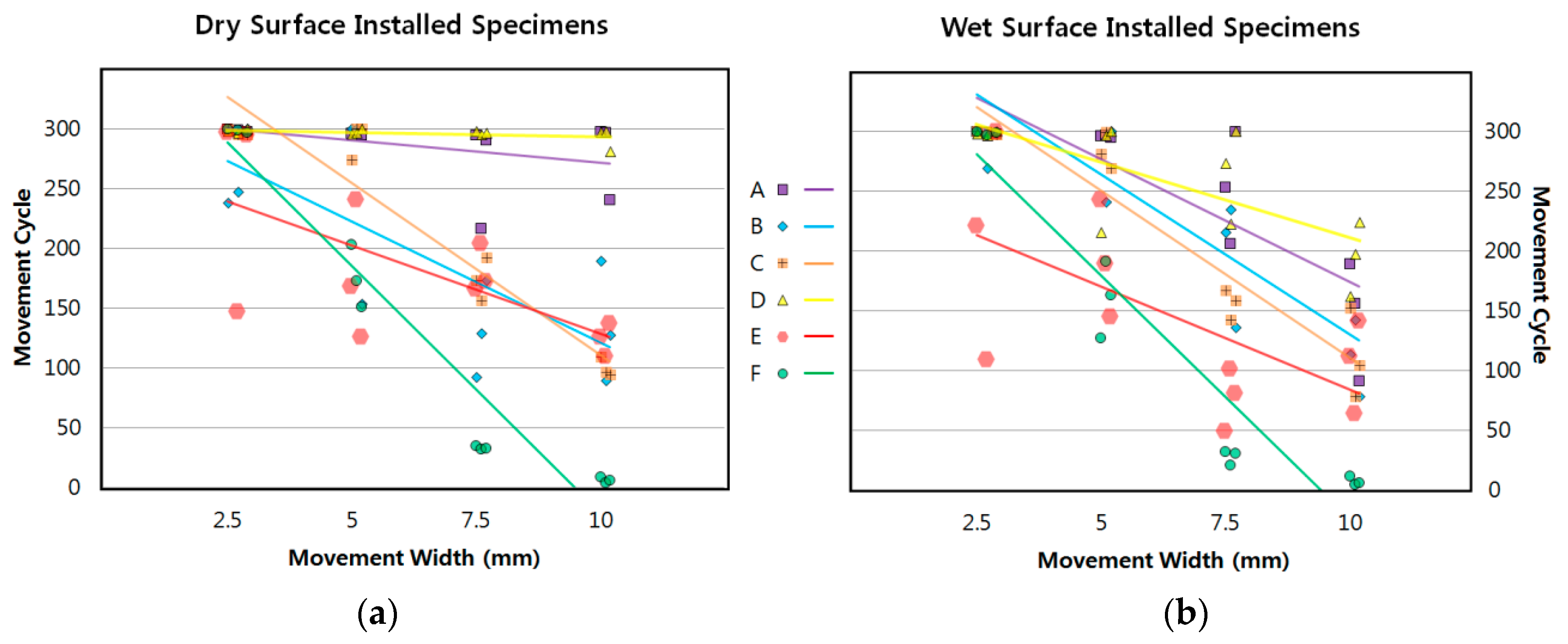
5.2. Expected Trend of Performance on Dry and Wet Surface Installation per Movement Widths
5.3. Estimation Method for Determining Successful Installation/Performance Rate for Waterproofing Membrane Systems
6. Conclusions
- The results of the test method show that a more accurate evaluation of waterproofing membranes is possible for below-grade construction. Out of the possible load modes and exposure conditions of the below-grade construction environment, concrete joint displacement and concrete surface humidity were particularly focused on as part of the evaluation criteria.
- Future applications of this test method should be designed to accommodate a larger range of parameters such as movement speed, cycle number, joint displacement width, and humidity level.
- To reduce reliance on visual inspection, a more accurate and non-destructive leakage cause analysis method is currently being developed. Many improvements are needed before this test method can be officially standardized.
Acknowledgments
Author Contributions
Conflicts of Interest
Abbreviations
| AF | Adhesion Failure |
| AIW | Australian Institute of Waterproofing |
| AS | Australian Standards |
| ASTM | American Standards for Test Methods |
| GB | Guo Biao |
| JIS | Japanese Industrial Standards |
| KCS | Korean Construction Specification |
| KS | Korean Industrial Standards |
| JSCE | Japanese Society of Civil Engineers |
| NL | No Leakage |
| OF | Overlap Failure |
| TF | Tensile Failure |
| UTM | Universal Testing Machine |
References
- Kim, S.Y.; Oh, S.K.; Kim, B.I. Artificial-Crack-Behavior Test Evaluation of the Water-Leakage Repair Materials Used for the Repair of Water-Leakage Cracks in Concrete Structures. Appl. Sci. 2016, 6, 253. [Google Scholar] [CrossRef]
- Oh, S.K. Test Method of Waterproofing System for Safety of Water Leakage and Waterproofing on the Underground Structure; Facility Safety: Seoul, Korea, 2005; pp. 64–77. [Google Scholar]
- Oh, S.K.; Kwak, K.S.; Choi, S.M.; Kwon, S.W. Improvement of Selection System of Waterproofing Method for Concrete Structure. J. Korea Inst. Build. Constr. 2007, 7, 99–106. [Google Scholar] [CrossRef]
- Kunieda, M.; Rokugo, K. Recent Progress of HPFRCC in Japan—Required Performance and Applications. J. Adv. Concr. Technol. 2006, 4, 19–33. [Google Scholar] [CrossRef]
- Ministry of Land, Transport and Maritime Affairs. KCS 41 40 01: Standard Specification on Waterproofing Construction; Architectural Institute of Korea: Seoul, Korea, 2016.
- Emmons, P.H. Concrete Repair and Maintenance Illustrated; R.S. Means Company: Los Angeles, CA, USA, 1994; p. 30. [Google Scholar]
- Oh, S.K.; Choi, S.Y.; Kim, S.Y.; Choi, S.M. A Study on the Characteristic of Responsiveness to the Movement by Construction Method Types of Exterior Wall Waterproof to Applied in Underground Concrete Structures. J. Korea Constr. Inst. 2014, 5, 903–904. [Google Scholar]
- BK Institute of Technology. Proposal on Composite Waterproofing Method Evaluation Method; Seoul National University of Science and Technology, Construction Technology Research Center: Seoul, Korea, 2016; pp. 40–43. [Google Scholar]
- Chungwoo Media. Guide to Design and Construction for Architectural Water Proofing System; Chungwoo Media Co., Ltd.: Seoul, Korea, 1992; pp. 33–44. [Google Scholar]
- Chang, S.-M.; Choi, S.M.; Oh, S.-K. Analysis of the temperature-humidity changing characteristics by the applying type of the waterproofing methods. Adv. Mater. Sci. Eng. 2015, 2015, 959502. [Google Scholar] [CrossRef]
- Lee, K.W.; Heo, T.S.; Yang, S.B. Review on the Proper Waterproofing Methods and Waterproof Agents for Underground Structures under Chloride Attack Environment in Incheon International Airport; Yoo Shin Engineering Corporation: Seoul, Korea, 2004; pp. 181–206. [Google Scholar]
- Kim, J.S.; Oh, S.K. An Experimental Study on the Non-Exposure Composite Waterproofing Method Used Adhesion Liquid and Sheet Integrate Waterproofing Material. Available online: http://www.riss.kr/link?id=T11194834 (accessed on 12 June 2017).


| System A: Non-Curable Asphalt Coating + Modified Asphalt Sheet (Composite Sheet) | System B: Curable (Hardening) Asphalt Coating + Modified Asphalt Sheet (Composite Sheet) |
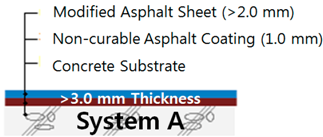 | 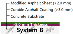 |
| System C: Half-Curable Asphalt Coating + Modified Asphalt Sheet (composite sheet) | System D: High Density Poly Ethylene (HDPE) Film + Rubber Sheet (composite sheet) |
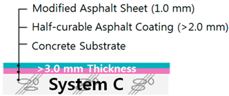 | 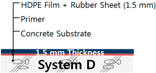 |
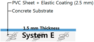
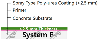
| System E: Polyvinyl Chloride (PVC) Sheet + Elastic Coating (composite sheet) | System F: Spray Type Poly-urea Coating (single-ply sheet) |
 |  |
| Item | Zero-Span Tensile Stress on Waterproofing Membranes | |||||
|---|---|---|---|---|---|---|
| Diagram | 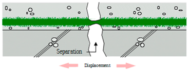 | |||||
| Fluid Type Waterproofing Membranes | Sheet Type Waterproofing Membranes | |||||
| Interaction Based on Types of Membrane | 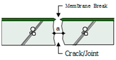 | 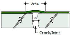 | ||||
| Principle | Before Break | After Break | Elongation | Before Break | After Break | Elongation |
| 0 | → ∽ | A | A + | 1 + | ||
| Standard | Tested Property | Speed/Rate | Movement Range | Cycle Number/Criteria | Applied Area |
|---|---|---|---|---|---|
| ASTM C1305 | Crack Bridging | 3.2 mm/h | 3.2 mm | 10×, breaking of membrane | roof/below-grade |
| ASTM D5849 | Fatigue Resistance | 1–2 mm/h (5 different ranges) | 1–2 mm (±0.05) | 500× for unexposed, 200× for exposed | roof/below-grade |
| KS F4934 | Fatigue Resistance Tensile Strength/Tearing Strength | 1 cycle/min or 200 mm/min | 2.0 mm | 20 °C 500× −20 °C 500× | below-grade |
| KS F 3211 | Fatigue Resistance Tensile Strength/Tearing Strength | 5 cycles/min or 500 mm/min | 2.0 mm | 2000× | roof/below-grade |
| KS F 4922 | Fatigue Resistance Tensile Strength/Tearing Strength | 5 cycles/min or 500 mm/min | 2.0 mm | 2000× | roof/below-grade |
| KS F 2622 | Fatigue Resistance | 1 cycle/min | 2.0 mm | 400× | roof/below-grade |
| KS F 4917 | Fatigue Resistance Tensile Strength/Tearing Strength | 1 cycle/2 min or 100 mm/min | 2.0 mm | 400× | below-grade |
| KS F 4919 | Crack Bridging Tensile Strength/Tearing Strength | 1 mm/min or 100 mm/min | 100 mm | Until break | roof |
| KS F 4935 | Substrate Movement | 1 cycle/min | 4.5 mm | 600 cycles | below-grade |
| Width Range | Description |
|---|---|
| 2.5 mm | Lower end of dry shrinkage range of normal weight concrete (400 to 800 microstrains, 1 microstrain = 1 × 2.54−5 mm) [6]. Waterproofing membrane systems unable to withstand this range of concrete displacement can be considered to be unsuitable for any below-grade concrete structure. |
| 5.0 mm | Higher end of dry shrinkage range of normal weight concrete. Waterproofing membranes that are able to withstand this range of concrete displacement can be considered to be suitable for well reinforced concrete structures without any cracks present. Direct installation over concrete joints should be avoided. Example of suitable application area: below grade wall and floor installation. |
| 7.5 mm | Higher than normally expected movement range of concrete structures. These types of movements could be caused by exposure to complex sources including freeze-thaw, dry shrinkage, structural settlement, water pressure and/or vibration from loads. Waterproofing membranes that are able to withstand this range of concrete displacement can be considered to be suitable for below-grade concrete structures. Examples of suitable application area: walls and floors with micro cracks, contraction joints. |
| 10.0 mm | Very high movement range of concrete structures. These types of movements could be caused due to extreme exposure to complex sources including freeze-thaw, dry shrinkage, structural settlement, water pressure and/or vibration from loads. Such length of movement can also be expected from expansion joints of large scale concrete slabs. Waterproofing membranes that are able to withstand this range of concrete displacement can be considered to be excellent for below-grade concrete structures. Examples of suitable application area: walls and floors with micro cracks, contraction joints, expansion joints, construction joints. |
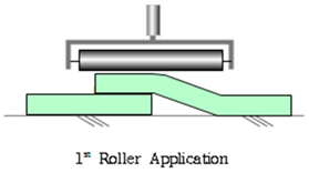
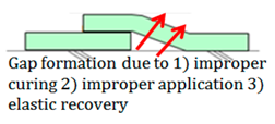
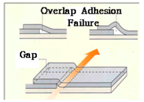
| Standard Application Method for Waterproofing Membrane Sheet Overlap Joint (Roller) | |
|---|---|
 |  |
 |  |
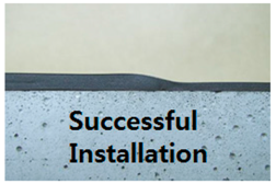 | 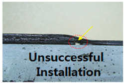 |
| Standard Name | Description/Relevance |
|---|---|
| ASTM D 7832 | A standard guide that oulines the minimum level of acceptable performance and properties of waterproofing membranes in below-grade walls. |
| KS F 4917, KS F 4935 | These test methods outline the required properties of waterproofing membranes. The two standards concern injection type sealants and waterproofing sheet membranes systems in below-grade walls and roofing. |
| GB 50108 | A standard that provides guidelines, list of testing methods, and description of proper workmanship and waterproofing membrane installation in below-grade construction. |
| JASS 8, JIS A 6909, JIS A 6021 JIS A 6008, etc. | JASS 8 is part of a list of specifications that provide installation practices of waterproofing membranes in concrete structures. JIS provides an extensive list of test methods for various types of waterproofing membranes and required properties, but mostly applies to roofing and above-grade walls. |
| BS 8102:2009 | Practice code for recommended waterproofing design guidelines (3 representative types) in below-grade construction. The code itself does not present a list of performance requirements for specific waterproofing membrane properties but refers to relevant BS standard testing methods. |
| AS 4858, AS 3740 | Standards that outline the performance requirement for waterproofing membranes in the wet areas of building interiors. |
| Criteria | Condition Interpretation | |||
|---|---|---|---|---|
| Surface Condition of Mortar Substrate | Surface | Number of specimens | ||
| Dry Surface: bewteen 8% and 12% surface relative humidity | 12 | |||
| Wet Surface: Above 12% surface relative humidity | 12 | |||
| Joint movement condition of Specimens | Movement Range | Number of Specimens | Displacement speed | |
| 2.5 mm | 3 | 50 mm/min | ||
| 5.0 mm | 3 | |||
| 7.5 mm | 3 | |||
| 10.0 mm | 3 | |||
| Cycle condition of Joint | Total Cycle Number | Durability Evaluation Grading Based on Cycle Number Endured | ||
| 300 cycles | Low Durability: 0–100 cycles | |||
| Medium Durability: 101–200 cycles | ||||
| High Durability: 201–300cycles | ||||
| Failure Type | Abbreviation | Examples and Illustrations of Each Failure Type | |
|---|---|---|---|
| Principle Illustration | Example Case | ||
| Tensile Failure | TF | 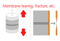 | 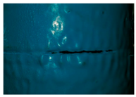 |
| Adhesion Failure | AF | 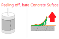 |  |
| Overlap Failure | OF |  | 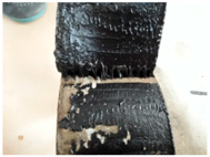 |
| Components | Dimensions + Parts | Illustration |
|---|---|---|
| 1. Case frame (for shaping mortar) |
| 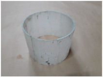 |
| 2. Threaded conduit | (a) Threaded conduit for upper slab
| 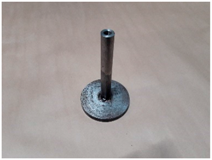 |
(b) Threaded conduit for bottom slab
| 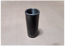 | |
| 3. Base frame | (a) Base Frame for upper slab
| 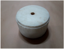 |
(b) Base Frame for bottom slab
| 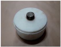 |
| Step 1 Mold Assembly | 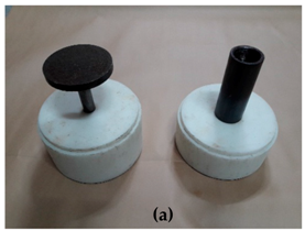 | 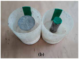 |
| Step 2 Casting and Curing | 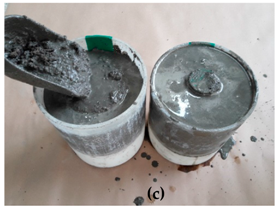 | 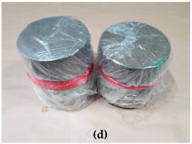 |
| Step 3 Demolding | 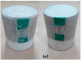 |  |
 |  | |
 |  |
| Tensile Failure | Adhesion Failure | Overlap Failure |
|---|---|---|
 | 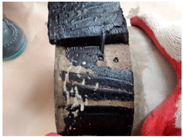 | 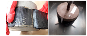 |
| Observable Conditions | ||
| Membrane tear | Bare concrete patches | Air bubble localization and gap |
| System | Surface & Specimen | Leaked Cycle Averaged per Specimens of Each Movement Width | ||||||||||||
|---|---|---|---|---|---|---|---|---|---|---|---|---|---|---|
| 2.5 mm | Fail. Type | Avg. | 5.0 mm | Fail. Type | Avg. | 7.5 mm | Fail. Type | Avg. | 10.0 mm | Fail. Type | Avg. | |||
| A | Dry | 1 | 300 | NL | 300 | 300 | NL | 300 | 300 | NL | 272 | 300 | NL | 280 |
| 2 | 300 | NL | 300 | NL | 217 | AF | 300 | NL | ||||||
| 3 | 300 | NL | 300 | NL | 300 | NL | 241 | AF | ||||||
| Wet | 1 | 300 | NL | 300 | 300 | NL | 300 | 253 | OF | 253 | 189 | AF | 147 | |
| 2 | 300 | NL | 300 | NL | 206 | AF | 156 | AF | ||||||
| 3 | 300 | NL | 300 | NL | 300 | NL | 96 | OF | ||||||
| B | Dry | 1 | 238 | OF | 262 | 300 | NL | 251 | 92 | AF | 131 | 189 | AF | 135 |
| 2 | 247 | OF | 300 | NL | 129 | AF | 89 | OF | ||||||
| 3 | 300 | NL | 153 | AF | 173 | AF | 127 | AF | ||||||
| Wet | 1 | 300 | NL | 289 | 300 | NL | 280 | 215 | AF | 195 | 113 | AF | 111 | |
| 2 | 269 | AF | 241 | AF | 234 | AF | 142 | AF | ||||||
| 3 | 300 | NL | 300 | NL | 136 | AF | 78 | AF | ||||||
| C | Dry | 1 | 300 | NL | 300 | 274 | OF | 291 | 176 | AF | 174 | 109 | AF | 99 |
| 2 | 300 | NL | 300 | NL | 156 | AF | 96 | AF | ||||||
| 3 | 300 | NL | 300 | NL | 192 | AF | 94 | OF | ||||||
| Wet | 1 | 300 | NL | 300 | 281 | OF | 283 | 167 | OF | 156 | 152 | AF | 111 | |
| 2 | 300 | NL | 300 | NL | 142 | OF | 72 | OF | ||||||
| 3 | 300 | NL | 264 | AF | 158 | AF | 104 | AF | ||||||
| D | Dry | 1 | 300 | NL | 300 | 300 | NL | 300 | 300 | NL | 300 | 300 | NL | 293 |
| 2 | 300 | NL | 300 | NL | 300 | NL | 300 | NL | ||||||
| 3 | 300 | NL | 300 | NL | 300 | NL | 281 | AF | ||||||
| Wet | 1 | 300 | NL | 300 | 215 | OF | 272 | 273 | OF | 265 | 162 | AF | 195 | |
| 2 | 300 | NL | 300 | NL | 222 | AF | 197 | AF | ||||||
| 3 | 300 | NL | 300 | NL | 300 | NL | 224 | OF | ||||||
| E | Dry | 1 | 300 | NL | 249 | 168 | AF | 178 | 166 | AF | 181 | 126 | AF | 124 |
| 2 | 147 | OF | 241 | AF | 204 | AF | 110 | AF | ||||||
| 3 | 300 | NL | 126 | AF | 172 | AF | 137 | AF | ||||||
| Wet | 1 | 221 | AF | 210 | 243 | OF | 192 | 49 | OF | 77 | 112 | AF | 105 | |
| 2 | 109 | AF | 189 | AF | 101 | AF | 64 | OF | ||||||
| 3 | 300 | NL | 145 | AF | 81 | OF | 141 | AF | ||||||
| F | Dry | 1 | 300 | NL | 300 | 203 | TF | 176 | 35 | TF | 33 | 9 | TF | 6 |
| 2 | 300 | NL | 173 | TF | 32 | TF | 4 | TF | ||||||
| 3 | 300 | NL | 151 | TF | 33 | TF | 6 | TF | ||||||
| Wet | 1 | 300 | NL | 300 | 127 | TF | 160 | 32 | TF | 28 | 12 | TF | 8 | |
| 2 | 300 | NL | 191 | TF | 21 | TF | 5 | TF | ||||||
| 3 | 300 | NL | 163 | TF | 31 | TF | 6 | TF | ||||||
© 2017 by the authors. Licensee MDPI, Basel, Switzerland. This article is an open access article distributed under the terms and conditions of the Creative Commons Attribution (CC BY) license (http://creativecommons.org/licenses/by/4.0/).
Share and Cite
Song, J.; Oh, K.; Kim, B.; Oh, S. Performance Evaluation of Waterproofing Membrane Systems Subject to the Concrete Joint Load Behavior of Below-Grade Concrete Structures. Appl. Sci. 2017, 7, 1147. https://doi.org/10.3390/app7111147
Song J, Oh K, Kim B, Oh S. Performance Evaluation of Waterproofing Membrane Systems Subject to the Concrete Joint Load Behavior of Below-Grade Concrete Structures. Applied Sciences. 2017; 7(11):1147. https://doi.org/10.3390/app7111147
Chicago/Turabian StyleSong, Jaeyoung, Kyuhwan Oh, Byoungil Kim, and Sangkeun Oh. 2017. "Performance Evaluation of Waterproofing Membrane Systems Subject to the Concrete Joint Load Behavior of Below-Grade Concrete Structures" Applied Sciences 7, no. 11: 1147. https://doi.org/10.3390/app7111147
APA StyleSong, J., Oh, K., Kim, B., & Oh, S. (2017). Performance Evaluation of Waterproofing Membrane Systems Subject to the Concrete Joint Load Behavior of Below-Grade Concrete Structures. Applied Sciences, 7(11), 1147. https://doi.org/10.3390/app7111147