You are currently viewing a new version of our website. To view the old version click .
Applied Sciences
  • Article
  • Open Access

7 November 2017

Performance Evaluation of Waterproofing Membrane Systems Subject to the Concrete Joint Load Behavior of Below-Grade Concrete Structures

,
,
and
1
Architectural Program of Graduate School, Seoul National University of Science and Technology, 232 Gongneung-ro, Nowon-gu, Seoul 01811, Korea
2
Graduate School of Housing and Urban Planning, Seoul National University of Science and Technology, 232 Gongneung-ro, Nowon-gu, Seoul 01811, Korea
3
School of Architecture, Seoul National University of Science and Technology, 232 Gongneung-ro, Nowon-gu, Seoul 01811, Korea
*
Author to whom correspondence should be addressed.
This article belongs to the Section Materials Science and Engineering

Abstract

Below-grade structures such as parking lots, underground subway tunnels, and basements are growing in scale and reaching deeper below-ground levels. In this type of environment, they become subject to higher water pressure. The concrete material of the structures is exposed to wet conditions for longer periods of time, which makes the proper adhesion of waterproofing membranes difficult. Joint movements from increased structural settlement, thermal expansion/shrinkage, and physical loads from external sources (e.g., vehicles) make securing durable waterproofing challenging. While ASTM Guides, Korean Codes, and BS Practice Codes on below-grade waterproofing stress the importance of manufacturer specification for quality control, ensuring high quality waterproofing for the ever-changing scale of construction remains a challenge. This study proposes a new evaluation method and criteria which allow for the selection of waterproofing membranes based on specific performance attributes and workmanship. It subjects six different waterproofing membrane systems (installed on dry and wet surface conditioned mortar slab specimens with an artificial joint to different cyclic movement widths) to 300 cycles in water to demonstrate that inadequate material properties and workmanship are key causes for leakages.

1. Introduction

For both above and below-grade concrete structures, waterproofing materials have often been selected based on minimum performance requirements and physical durability tests. The scale of below-grade construction today is larger and deeper, and structures face degrees of degradation that have not been properly considered before. Construction and expansion joints in particular are subject to heavier loads due to structural settlement and higher water pressure []. In these cases, conventional waterproofing methods are not viable in these types of environments. For example, cementitious systems have been considered as a proper waterproofing method for shallow foundation, below-grade construction due to their high adhesion performance on humid concrete surfaces, and easy access for repairs and maintenance []. In larger and deeper below-grade construction, however, cementitious materials are not recommended due to their lack of crack-bridging properties and responsiveness to structural settlement and joint movement.
Many Asian countries are beginning to replace their waterproofing membranes with new types designed specifically for below-grade construction. Existing standards, guidelines (specifications), and test methods have not been updated to reflect the changing scale of below-grade construction. Proper evaluation of waterproofing membranes can therefore be difficult. To remedy the issue, this study proposes a new test method and evaluation criteria designed to assure quality control for construction personnel including designers, manufacturers, engineers, and inspectors. The demonstration of the test method shows that an objective evaluation of waterproofing membrane installation workmanship is possible.

2. Below-Grade Waterproofing Membrane Systems

2.1. Below-Grade Concrete Structure Waterproofing Methods

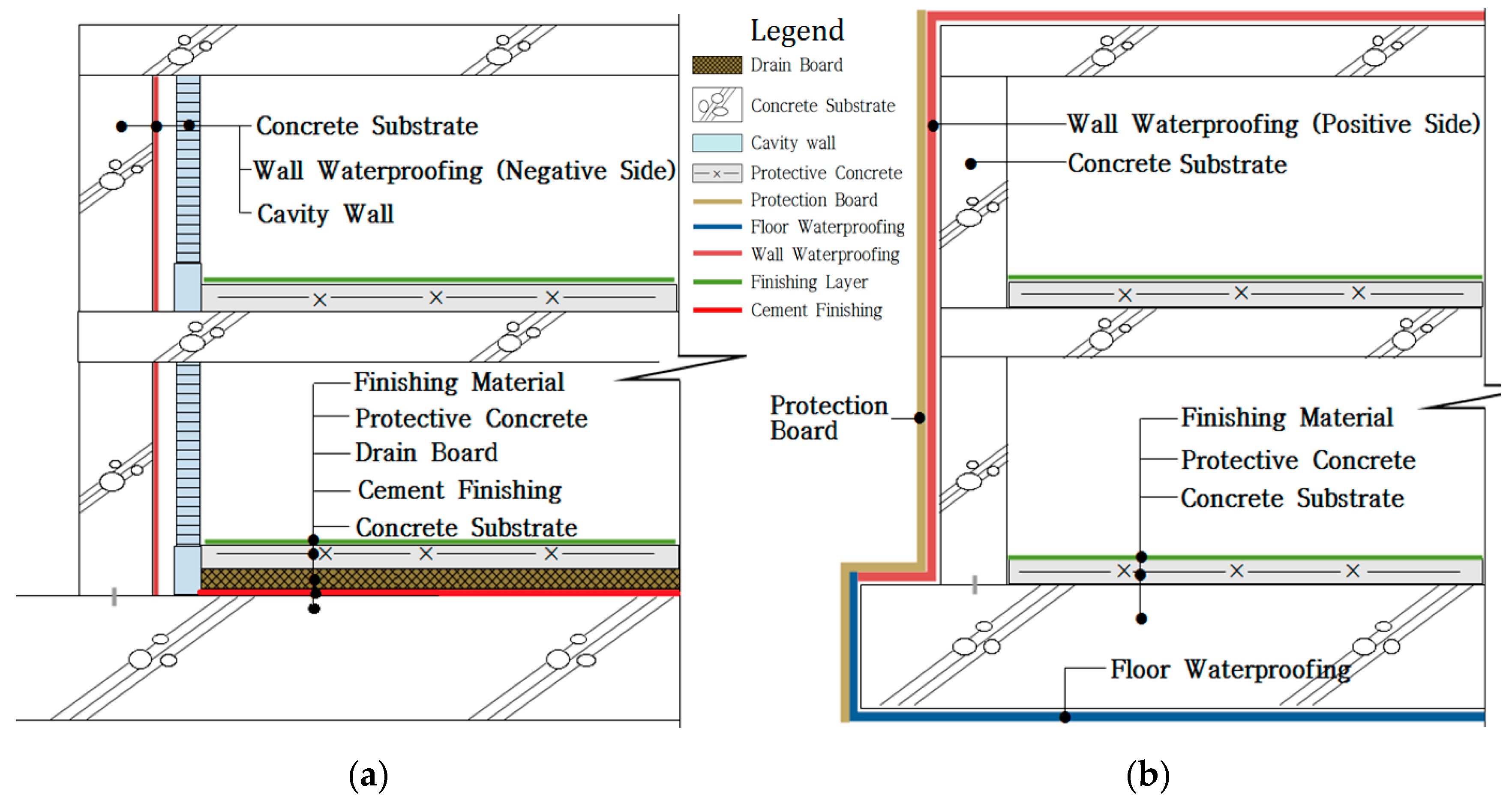
In the case of below-grade concrete structures, there are positive side and negative side waterproofing methods. Refer to Figure 1 for an illustration of this.
Figure 1. Comparison of positive and negative side waterproofing methods; (a) negative side waterproofing; (b) positive side waterproofing.
Negative side waterproofing allows for the penetration of water into the interior space of the structure, where the water is discharged by the drainage system. This method commonly uses cementitious materials which lack crack-bridging properties and chemical resistance. As it naturally allows substrates to contact water, there is also a risk of corrosion. Positive side waterproofing on the other hand, provides a barrier-like protection by preventing water penetration and substrate contact []. This method commonly uses elastomeric membranes with high tensile strength and chemical resistance. The downside is the high workability requirements and extra care required during installation on wet surfaces. Many physical durability test methods evaluate both positive and negative side waterproofing materials using the same criteria, without properly accounting for the differences between the materials. The test method proposed in this study aims to avoid such problems.

2.2. Selected Waterproofing Membrane Systems for Evaluation

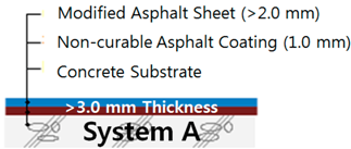
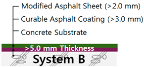
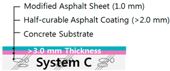
Five different types of composite sheet waterproofing membranes, and one single ply sheet waterproofing membrane commonly used for positive side waterproofing were selected. The membranes were tested with Korean Industrial Standards (KS F 4917 and KS F 4935) compliant methods. The details of each membrane are described below with an illustration shown in Table 1.
Table 1. Waterproofing membranes system installation layout on substrate surface (exposed).
System A: Non-curable asphalt coating + modified asphalt sheet (composite sheet)
This membrane is an asphalt waterproof sealant with 95% solidity. It is normally applied on concrete substrates with a 1 mm thickness. A modified asphalt impregnated into a non-woven fabric layer (>2.0 mm) is adhered onto the sealant, resulting in a total thickness of >3.0 mm. This membrane is a composite type which does not require a primer.
System B: Curable (hardening) asphalt coating + modified asphalt sheet (composite sheet)
This membrane is a soluble asphalt waterproof sealant with 85% high solidity. It is normally applied on concrete substrates two times in succession to form a layer with a thickness of >3.0 mm. A modified asphalt impregnated into a non-woven fabric layer (>2.0 mm) is adhered onto the sealant, resulting in a total thickness of >5.0 mm. This membrane is a composite type which does not require a primer.
System C: Half-curable asphalt coating + modified asphalt sheet (composite sheet)
This membrane is a half-curing (hardening) asphalt compound comprised of high elasticity rubber and high durability mineral filler agent with a >2.0 mm thickness. A modified asphalt impregnated into a non-woven fabric layer (1.0 mm) is adhered onto the sealant, resulting in a total thickness of >3.0 mm. This membrane is a composite type which does not require a primer.
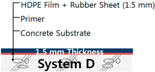
System D: High density poly ethylene (HDPE) film + rubber asphalt (composite sheet)
This membrane is a composite, self-adhesive type comprised of a 1.5 mm thick HDPE film and a rubber sheet. Normally, a primer compound designed for asphalt adhesion is applied on the concrete substrate in conjunction. The overlap joint is finished with asphalt sealant.
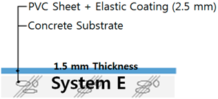
System E: Polyvinyl chloride (PVC) sheet + elastic coating (composite sheet)
This membrane is a polyvinyl chloride film combined with an elastic coating to form a layer with a thickness of 2.5 mm. The PVC sheet is produced by combining nonwoven fabric and a mineral elastic sealant film. The PVC sheet is applied on the concrete base and the overlap joint is finished by hot-air welding.
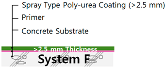
System F: Spray type poly-urea coating (single-ply sheet)
This membrane is a poly-urea spray type coating material applied after primer application on concrete substrates. In normal practice, the poly-urea is uniformly sprayed on the entire concrete surface with spraying equipment to form a waterproof layer with a thickness of >2.5 mm.

3. Loading Modes and Exposure Conditions

The load factors in below-grade construction environments have not yet been clearly defined in current international standards and test methods. The current test methods cannot provide clear evaluation criteria, and relying on manufacturer specifications for quality control often leads to poor waterproofing workmanship. It is important to clearly define the loading modes as they can have a significant effect on waterproofing membrane durability. This study proposes three main loading modes and exposure conditions in Section 3.1, Section 3.2 and Section 3.3. Section 3.4 compares existing international standards to disclose a lack of connection between manufacturer specifications and performance evaluation criteria. Section 3.5 explains in detail the proposed evaluation criteria, which are used while demonstrating the test method.

3.1. Effects of Zero-Span Tensile Stress, Displacement Range, and Speed of Concrete Joint on Waterproofing Membrane

Most tensile strength tests today are conducted with free-film specimens. A more realistic testing method would require studying the effects of zero-span tensile stress on waterproofing membranes applied on moving cracks. The JSCE Standard (JSCE 2002) lists zero-span tensile evaluation as one of the requirements for determining waterproofing membrane performance. Studies in Japan have revealed that the localization of waterproofing membrane cracking occurs directly over the concrete joint displacement area [].

3.1.1. Zero-Span Tensile Stress

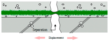
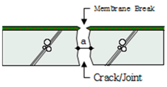
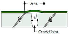
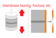
Table 2 displays the effect of zero-span tensile stress on different types of waterproofing membranes adhered over concrete cracks/joints. In the case of fluid-applied/coated/cementitious waterproofing membranes, the elongation reaches from 0 to a (span) directly. The membrane breaks as the tensile stress is applied directly on the adhesive bond between the membrane and the concrete surface, as well as and the cohesive bond within the membrane itself.
Table 2. Zero-span tensile stress mechanism of waterproofing membrane on concrete joint.
In the case of composite membrane sheets, tensile stress distribution is interrupted by the heterogeneous layers of the membrane structure. This mechanism explains why membrane types should be evaluated by the same load modes. An evaluation of the displacement load response can produce more realistic data on the performance of waterproofing membranes adhered over a moving crack/joint, and is included in the proposed test method.

3.1.2. Joint Displacement Range, Speed, and Cycle

To assign a value for the variables that define the range, speed, and cycle number of the joint displacement load, existing test methods on fatigue resistance, tensile strength, and crack bridging have been studied. The studies reveal that the load behaviors of concrete joints/cracks differ by the environmental parameters relevant to the respective national standards. The movement width, speed, and cycle numbers are all subject to change based on the requirements of the test purpose. Refer to Table 3 for the list of relevant test methods studied.
Table 3. Joint displacement range, speed, and cycle number conditions in ASTM and KS.
For this proposed test method, the crack/joint movement range outlined in “KS F 2622 Performance Evaluation Testing Methods on Membrane Waterproofing Method”, [] was used to design the evaluation criteria. The displacement load speed was set to 50 mm/min and the total cycle number was set to 300.
The displacement load width range was divided into four different widths to ensure that the results take into account various types of movements that occur in below-grade construction. Refer to Table 4 for the crack/joint movement ranges in the KS F 2622 standard.
Table 4. Crack/joint movement range in “Proposal on Composite Waterproofing Method Evaluation Method”.

3.2. Workmanship and Adhesion Property of Waterproofing Sheet Membrane Overlap Joint

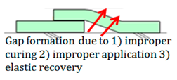
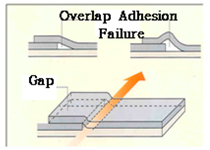
During the installation of waterproofing membranes, overlap joints naturally form []. If the waterproofing membranes are not sufficiently cured, or if the concrete surfaces are not cleaned prior to installation, gaps can form along the interface of these overlap joints. Thicker waterproofing sheets have a higher elastic modulus, and elastic recovery applies additional straining force on the adhesion [].
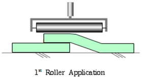
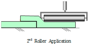
In most cases, overlap joint adhesion is a highly technical procedure, and poor workmanship can easily lead to the gaps forming. As illustrated in Table 5, a second rolling operation on the lower portion of the overlap joint is required to ensure that the membranes securely bond to the concrete substrate [].
Table 5. Illustration of application method for waterproofing membrane sheet overlap.
In order to account for these factors, the proposed test method includes a visual inspection of the overlap joints for signs of leakages as a measure of workmanship.

3.3. Adhesion on Wet Concrete Substrate and Waterproofing Membrane

In high rainfall regions, the humidity of below-grade construction sites can reach above preferred levels, and it becomes difficult to keep the concrete substrates dry. According to Korean Construction Specification (KCS 41 40 01:2016, Standard Specification on Waterproofing Construction), waterproofing membranes should be installed on a concrete surface with less than 8% humidity. In many below-grade construction sites, however, the surface relative humidity of concrete can be higher than 12%. This results in poor adhesion and low-quality installations. Due to labor costs and construction schedules, the consideration of humidity is often omitted from manufacturer specifications [].
Manufacturers in many Asian countries have begun to develop waterproofing materials that can maintain high levels of adhesion on wet substrate surfaces []. However, there is still a lack of standardized test methods for this type of performance. Therefore, the proposed test method includes evaluation criteria designed for measuring adhesion performance, specifically on wet surfaces.

3.4. Existing Evaluation Methods for Waterproofing Membrane Systems

International test methods today evaluate the physical durability of waterproofing membranes using a number of categories: tensile/tearing strength, adhesion strength, water pressure resistance, thermal resistance, chemical resistance (alkali and chlorine), and elongation []. Table 6 below lists the specific reference materials from each national standard body.
Table 6. International standards on required waterproofing membrane properties.
While the above standards define what ideal waterproofing should be, they do not provide clear instructions on how ensure proper workmanship. In general, the standards recommend following manufacturer specifications, but do not provide quality control instructions for each specification. This reiterates the absence of proper quality assurance methods for below-grade construction.

3.5. New Proposed Evaluation Method and Criteria

Based on the loading modes and exposure condition outlined in the above sections, a new evaluation method has been designed and proposed in this study. This method is intended to evaluate the concrete joint load behavior response performance and workability performance of waterproofing membrane systems intended to be used in below-grade construction. Table 7 and Table 8 display the evaluation criteria that include all the loading modes outlined above to be used in the test method demonstration.
Table 7. Test specimen degradation evaluation criteria for concrete joint load behavior performance.
Table 8. Material property and workability evaluation based on failure types and causes.

4. Test Method and Apparatus

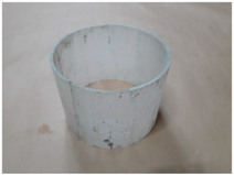
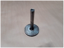
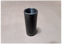
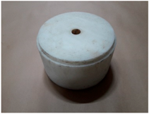
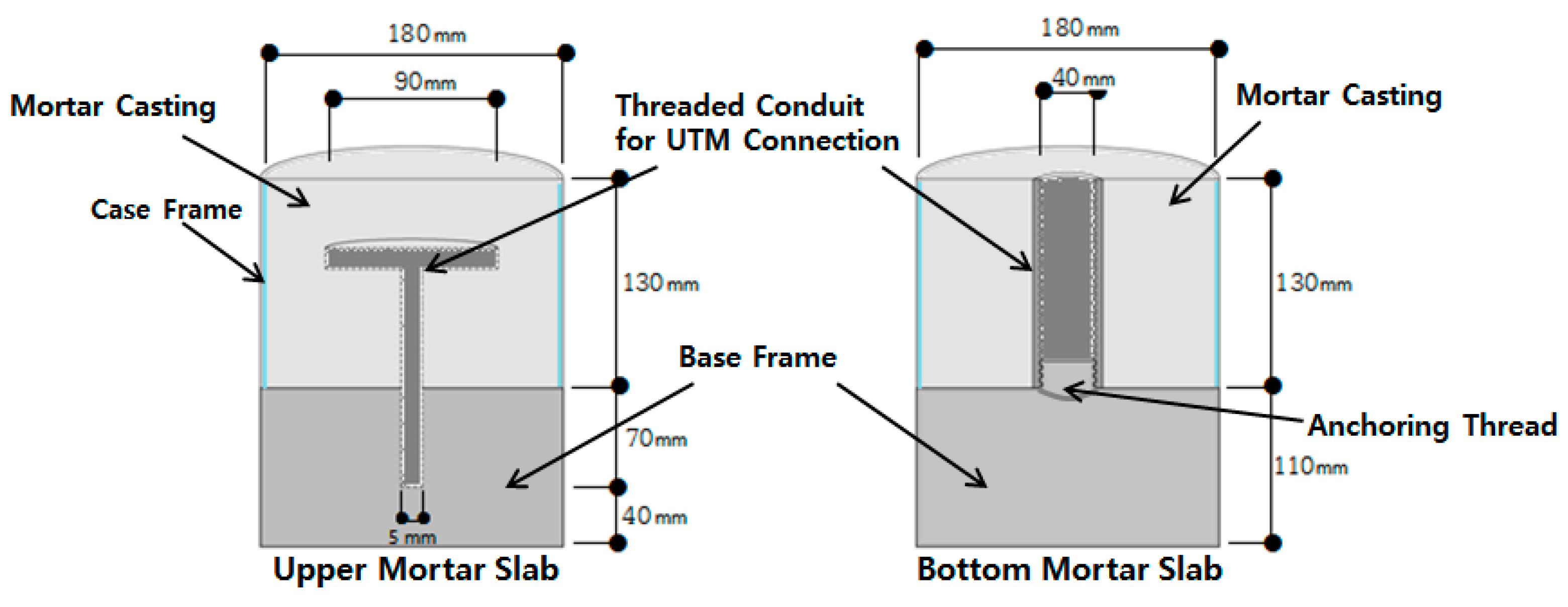
The test specimen is comprised of upper and bottom cylindrical mortar slab parts. The two parts are placed together to form a separation gap at the interface. This gap represents a concrete joint or crack. The waterproofing membrane is installed perpendicular to the gap of the mortar slab specimen. For this test demonstration, mortar was used instead of concrete for easier workability. The mixture ratio of water to cement to sand is 0.5:1:3. Refer to Table 9 for the details on the assembly. Once the mortar is mixed and cast into the mold, the mortar forms a cylindrical slab. Refer to Figure 2 for details on the dimensions of the mortar slab casting in the mold.
Table 9. Components and details of mold to make mortar slabs.
Figure 2. Mortar specimen casting in mold concept diagram.

4.1. Mold Assembly

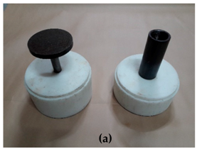
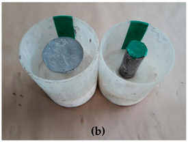
The threaded conduits are installed onto their corresponding bases, and the case frame is placed on each of the base frames (upper and bottom slabs) {Step 1 (a) of Table 10}. Masking tape is used to seal the split section of the case frame to prevent bleeding during casting. A rounded tape is cut out (Ø 50 by 5 mm) to cover the hole of the threaded conduit for the bottom mortar slab to prevent any loose mortar entering and blocking the conduit hole {Step 1 (b) of Table 10}.
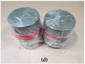
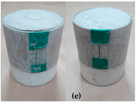
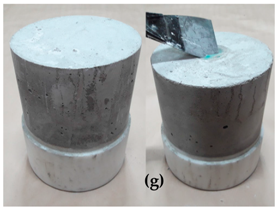
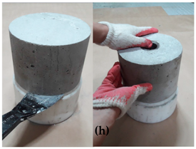
Table 10. Procedure for mortar specimen preparation.

4.2. Mortar Slab Casting and Curing

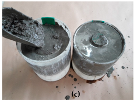
Once the mold preparation is complete, mortar is cast into the molds. The threaded conduit is entirely covered with mortar. The bottom mortar slab mold should be completely full as well, but the mortar should not reach up to the opening of the threaded conduit. Rod tamping is used to ensure that air voids are eliminated as much as possible {Step 2 (c) of Table 10}. The casted fresh mortar is then cured in the laboratory for three days in ambient conditions (24 ± 3 °C, 65 ± 3% RH). Plastic sheets should be used to cover the molds while curing to prevent evaporation {Step 2 (d) of Table 10}.

4.3. Mortar Slab Demolding

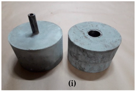
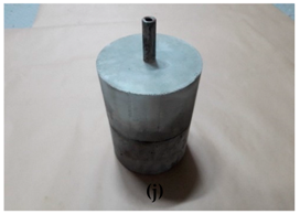
Once the mortar slabs are cured, the plastic sheet is removed {Step 3 (e) of Table 10}. The masking tape is peeled off and the case frame is removed by peeling the case at the split section using a spatula or any edged tool {Step 3 (f) of Table 10}. For the bottom mortar slab, if a mortar layer forms at the threaded conduit opening, a metal scraper is used to remove the layer. The edges must be clean from any mortar debris to ensure a smooth connection with the testing apparatus {Step 3 (g) of Table 10}. For mortar removal from the base frames, the upper mortar slab is pulled out, and the bottom mortar slab is screwed off. A scraper or some other sharp-edged tool is used to separate the mortar from the base frame interface for easier removal {Step 3 (h) of Table 10}. Once the mortar slabs are demolded {Step 2 (i) of Table 10}, the upper mortar slab is placed on top of the bottom mortar slab to form a mortar specimen set {Step 3 (j) of Table 10}.

4.4. Conditioning of Mortar Slab

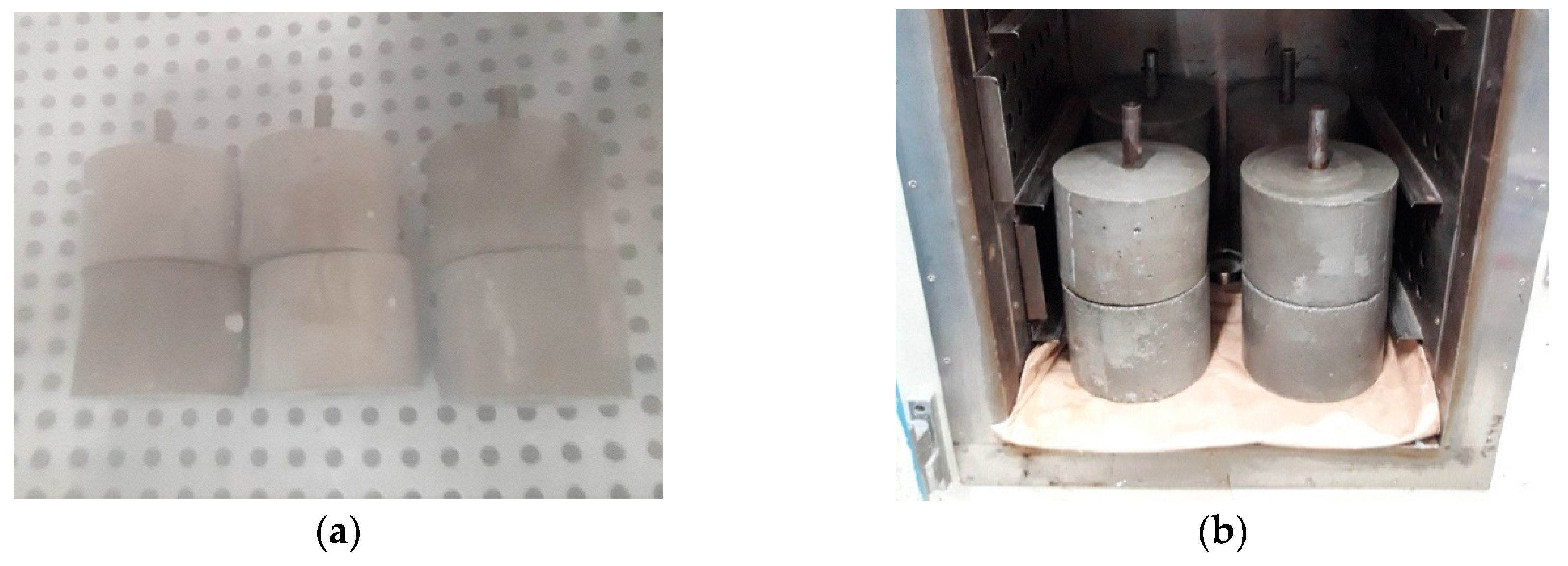
The demolded mortar specimens are placed in water for seven days for curing and saturation. After they are removed from water, their surfaces are wiped with a cloth until they are moderately dry. The specimens are then placed in a desiccator with a relative humidity of between 8% and 12% (inclusive) for dry surface conditioned specimens, and above 12% for wet surface conditioned specimens. When the specimens are taken out of the desiccators, their surfaces are measured with a high frequency relative humidity sensor in ambient conditions (temperature at 20 ± 3 °C, and relative humidity at 60 ± 5%). Prior to membrane installation, a relative humidity sensor should read higher than 12% for the wet surface condition, and between 8~12% for the dry surface condition. Refer to Figure 3 for details.
Figure 3. Mortar section preparation for surface conditioning (a) curing in water chamber; (b) placement in desiccator chamber.

4.5. Installation of Waterproofing Membrane on Mortar Slabs

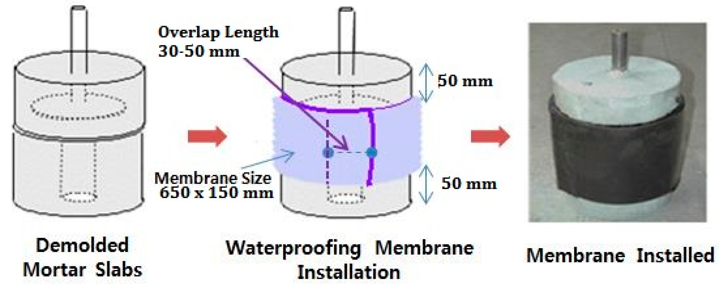
The waterproofing membrane is cut into a 650 by 150 mm rectangular piece. The membrane is installed on the mortar slabs placed together with the short dimension applied perpendicular to the joint gap. When applying the waterproofing membrane sheets, an overlap joint with a minimum width of 30–50 mm is made. When the waterproofing membrane is adhered over the joint, 50 mm of the exposed area from the slab edge to the waterproofing membrane should be formed. Details are shown in Figure 4.
Figure 4. Waterproofing membrane installation dimension.
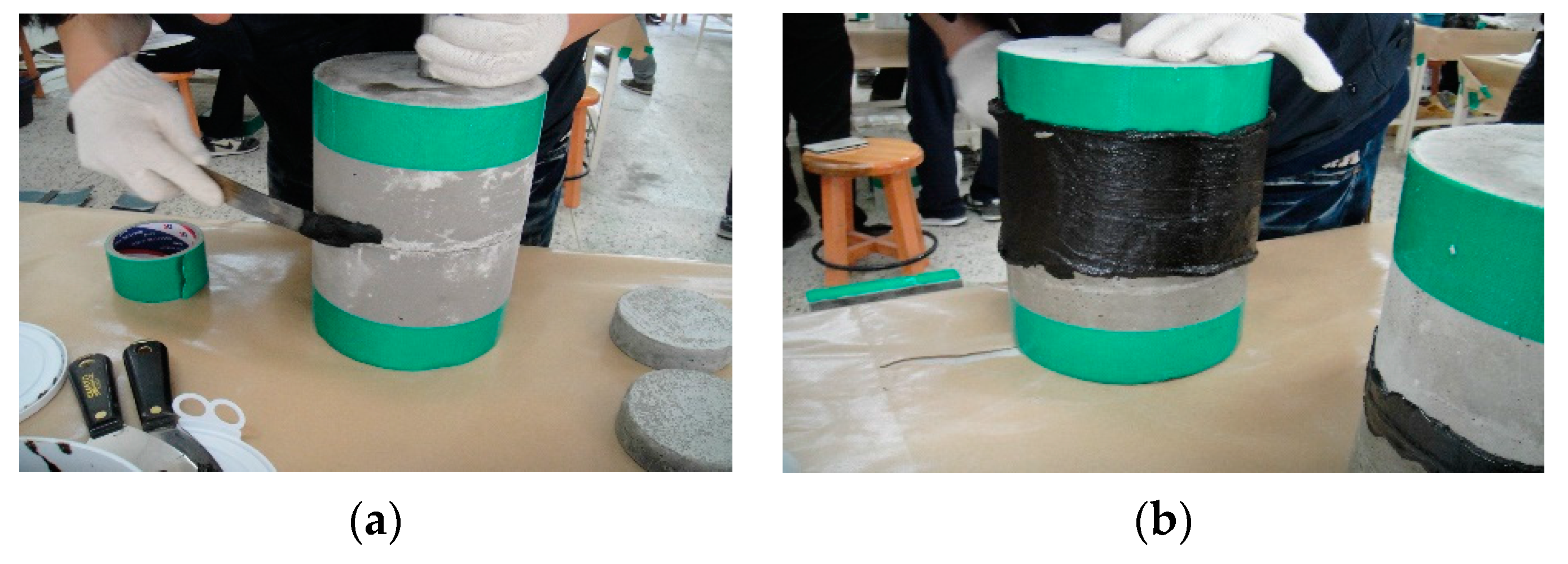
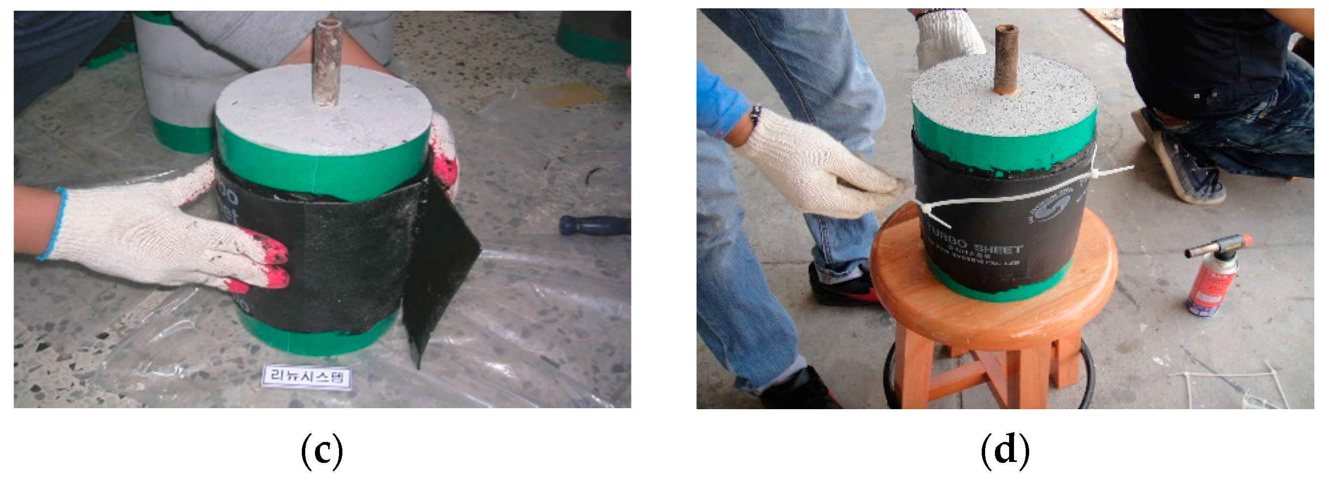
Waterproofing membranes are installed following manufacturer specifications. For this demonstration, installation was conducted in front of licensed representatives from each waterproofing membrane manufacturer to ensure that the installation process was carried out properly. The installation is conducted in a laboratory setting with ambient conditions (temperature of 20 ± 3 °C, relative humidity of 60 ± 5%). Refer to Figure 5 for details.
Figure 5. Waterproofing membrane installation process illustrated (a) mortar sections placement and surface treatment; (b) primer, adhesive, or other adhesion material application; (c) waterproofing sheet application; (d) Test specimen complete and ready for testing.
Once the assembly is complete, the specimens are set to rest in a curing room for a maximum of seven days (for this demonstration, the manufacturer specifications were followed).

4.6. Testing Apparatus Design and Setting for Joint Displacement Testing

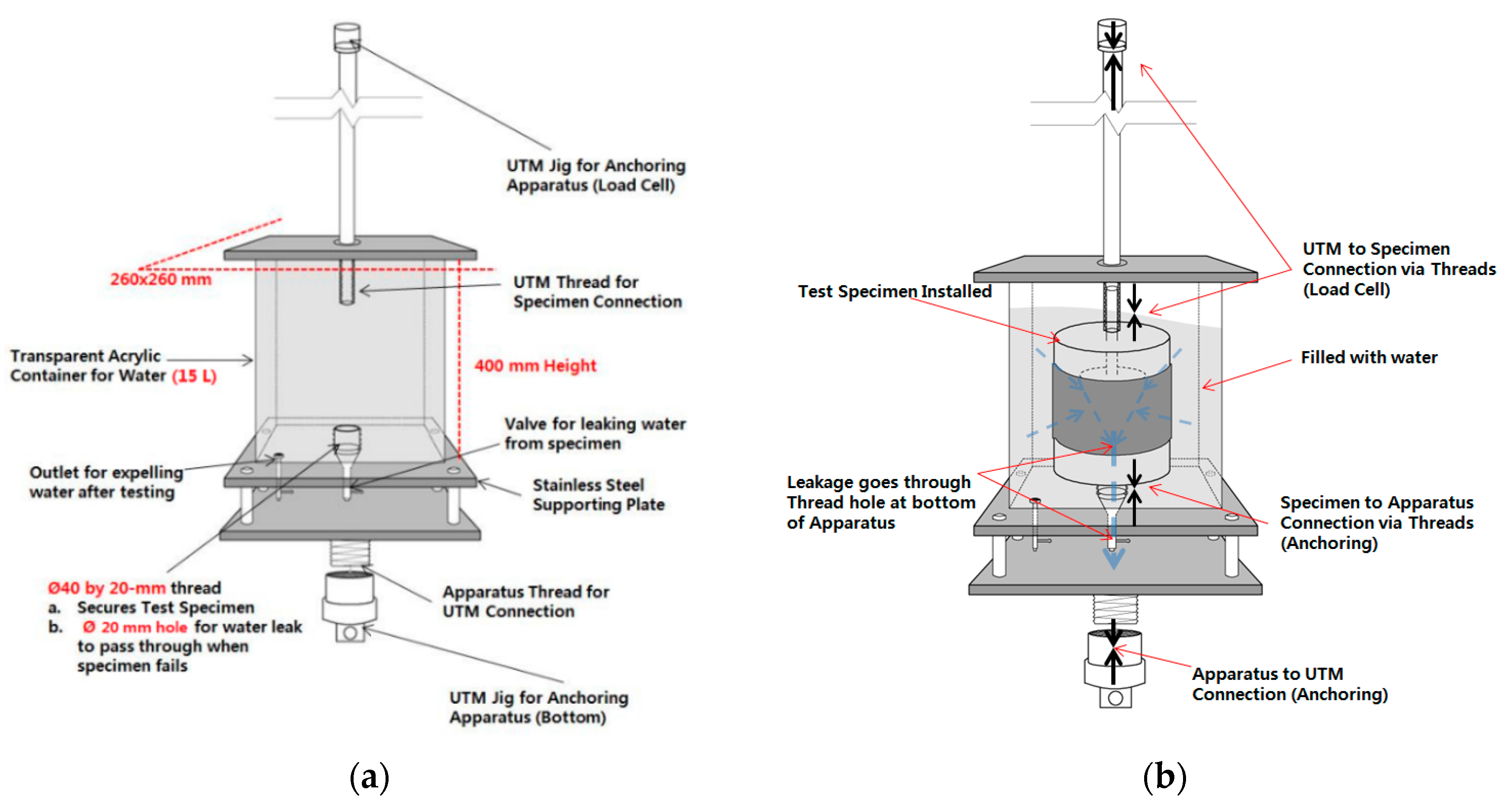
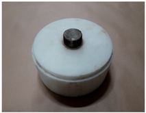
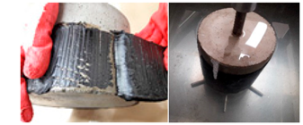
The apparatus consists of a UTM (Universal Testing Machine) and a specially structured acrylic container. The test specimen is first installed in the acrylic container, which is then filled with water, and inserted into the UTM for displacement load testing. Once installed, the upper mortar slab section of the specimen is pulled up and down vertically in relation to the bottom slab, which is fixed to the apparatus. Refer to Figure 6 for details.
Figure 6. Testing apparatus illustrated (a) Container and components; (b) Setting in apparatus.
Below is a set of more detailed steps for installing the specimen onto the testing apparatus:
(1)
The test specimen is installed into the acrylic chamber apparatus by screwing the threaded conduit of the bottom mortar slab onto the metallic thread at the bottom of the chamber.
(2)
The container is filled with approximately 15 L of water. The specimen should be completely submerged in water.
(3)
The chamber is installed onto the UTM. The bottom connection is anchored with a rivet to the jig of the UTM. The upper mortar slab threaded conduit is then anchored to the upper jig of the UTM.
(4)
The joint displacement speed (construction joint movement rate) is set to 50 mm/min.
(5)
The test is initiated in the conditions outlined in Table 7.

4.7. Failure Type Analysis Method of Tested Waterproofing Membrane

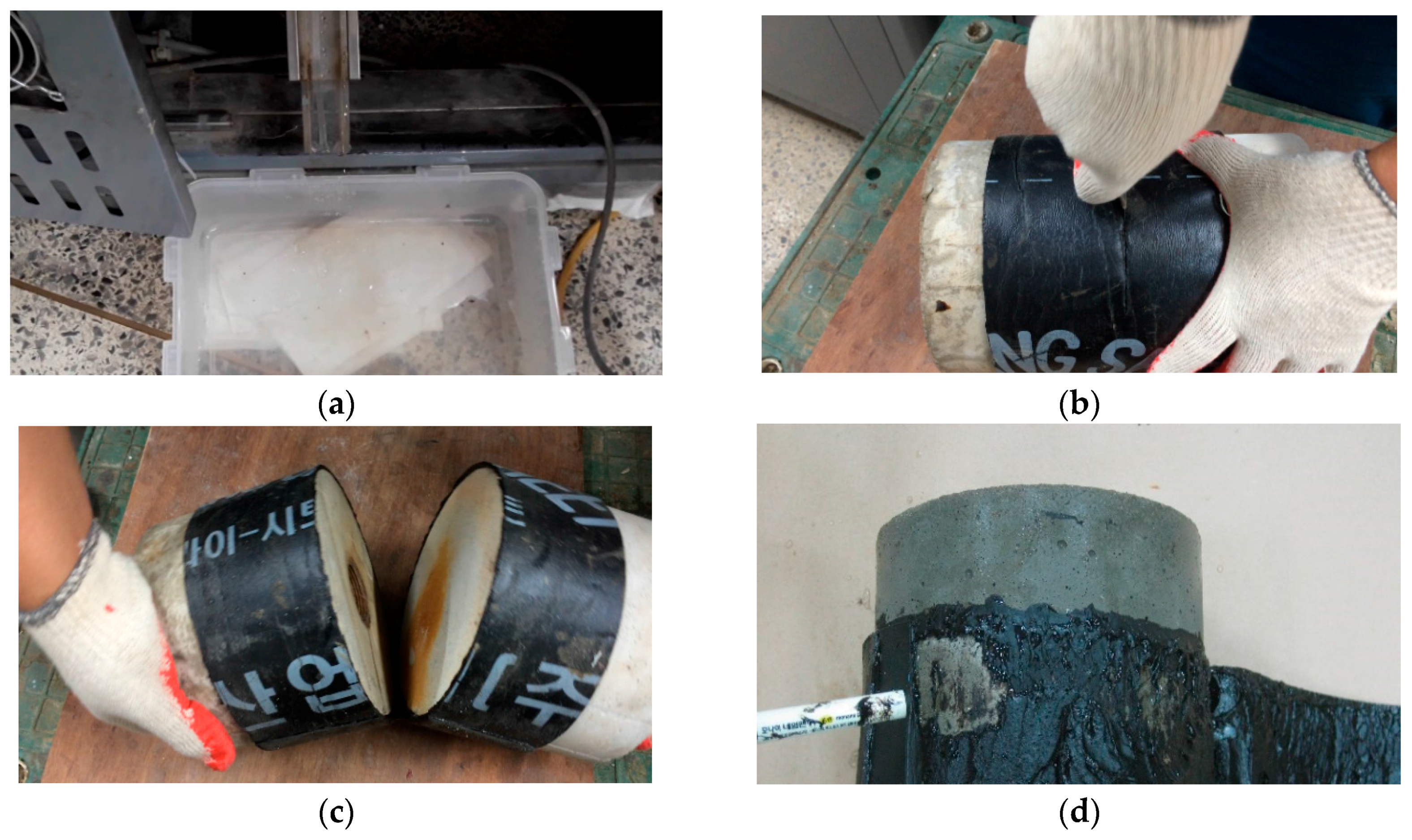
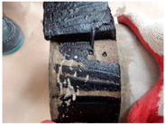
When leakage occurs with a specimen during testing, the conditions of the specimen inside the testing apparatus are observed, and anomalies such as tearing are recorded. The specimen is then taken out of the apparatus and undergoes a membrane removal process as shown in Figure 7.
Figure 7. Waterproofing membrane evaluation after testing (a) leakage detection; (b) incision to separate mortar slabs; (c) checking interior surface; (d) analysis.
The main cause of the leakage is then classified into one of following three types of failure; Tensile Failure (TF), Adhesion Failure (AF), and Overlap Failure (OF). This process is mostly visual as the identification is difficult at this stage of the test. A close approximation is made by identifying key observable patterns that correspond to each failure type.
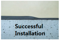
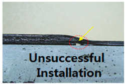
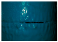
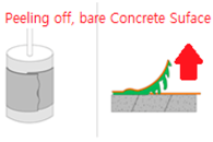
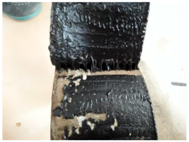
Any visible tears in the membrane surface indicate ‘Tensile Failure’. If there are no tears, the waterproofing membrane is peeled off using a knife. The exposed areas can form a direct leakage path at the interface of the membrane and the mortar surface. This failure type is indicated as ‘Adhesion Failure’. If traces of air bubbles localize over the overlap joint, and if a gap is clearly visible under the overlap section during membrane removal, this indicates ‘Overlap Failure’. Refer to Table 11 for an illustration of this.
Table 11. Identification of failure types for leaked specimens.

5. Evaluation of Six Waterproofing Membranes Using the Proposed Testing Method

The results of the tests on the six waterproofing membranes are displayed in Table 12. For membranes that leaked during the testing, the number of cycles and the failure type were recorded respective to the surface condition (dry and wet) and movement width. Specimens that did not leak during the 300 cycles were recorded as ‘no leak’ (NL). Most of the membranes were able to withstand at 2.5 mm, and varied in terms of the results at 5.0 mm, 7.5 mm and 10.0 mm. The nature of the failures was determined using the observable conditions and methods in Section 4.4 (Failure Type Analysis Method of Tested Waterproofing Membrane System) and Table 12.
Table 12. Results of the leaked cycles per each waterproofing system averaged.

5.1. Evaluation Results

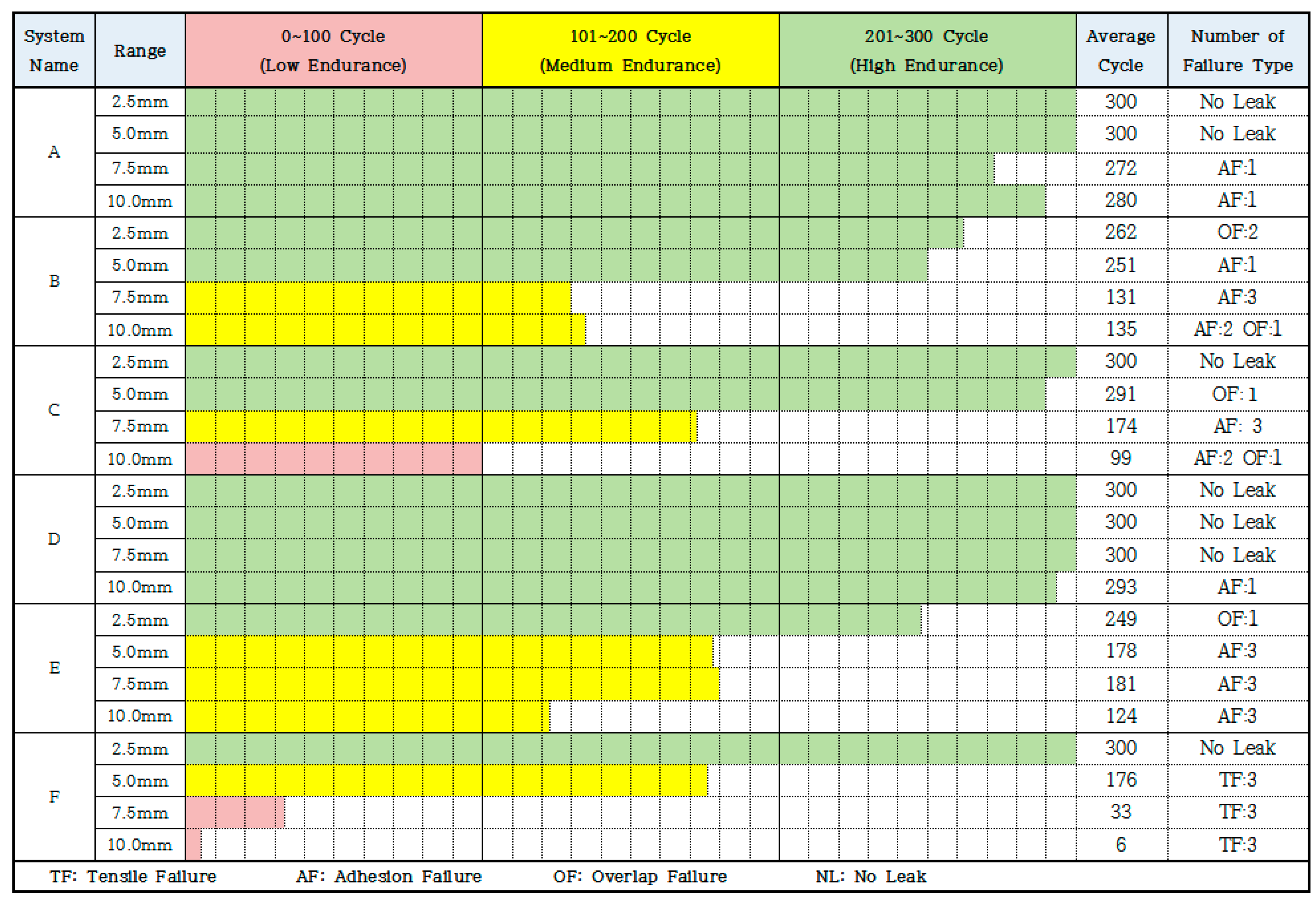
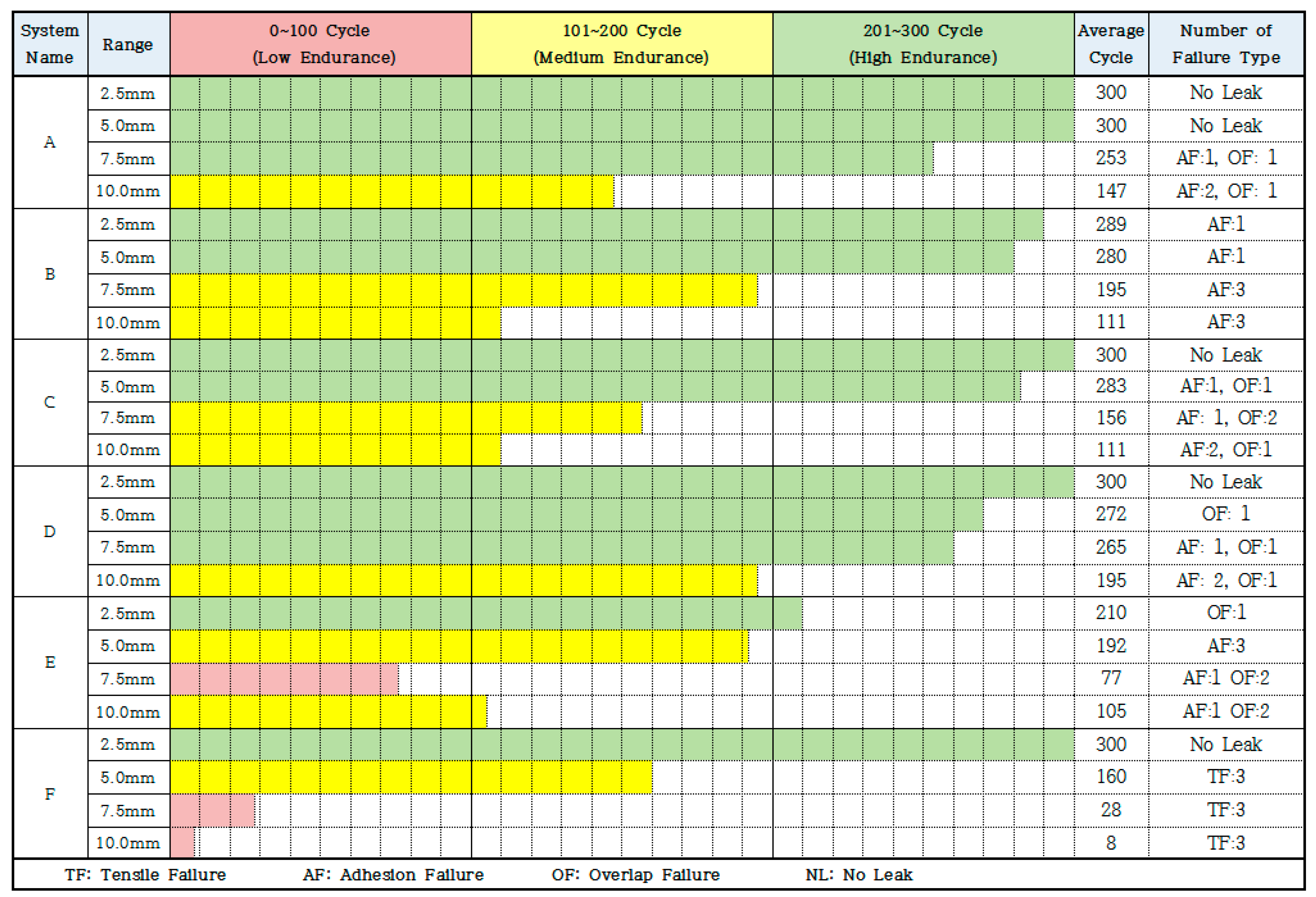
Most of the failures were adhesion failures with the exception of the spray type poly-urea waterproofing membrane (System F), whose lack of tensile property was visible from 5.0 mm onwards, suggesting its unsuitability for below-grade waterproofing construction.
The non-curable asphalt coating composite sheet (System A) and polyvinyl chloride (PVC) + elastic coating composite sheet (System D) displayed the highest performance. Systems A and D had a few specimens that leaked water with high performance on dry surfaces, but showed failures in the higher width range of joint displacements. Overlap failure was more common with wet conditioned specimens, confirming that wetness has a negative effect on adhesion at overlap sections.
Lastly, the number of cycles was averaged between the results of three specimens for each movement width range to express an estimation of the endurance performance. Each membrane system’s endurance performance was evaluated by the following expressions; the 201–300 cycle range expresses high endurance performance with the corresponding load behavior (represented in green), 101–200 cycle range expresses medium endurance performance (represented in yellow), and 0–100 cycle range expresses low endurance performance (represented in red). The averaged cycle numbers of the three specimens for the individual systems from Table 12 were displayed separately for dry surface installed specimens and wet surface installed specimens, as shown in Figure 8 and Figure 9.
Figure 8. Endurance cycles of dry surface test specimens (Averaged).
Figure 9. Endurance cycles of wet surface test specimens (Averaged).

5.2. Expected Trend of Performance on Dry and Wet Surface Installation per Movement Widths

The averaged leaked cycle numbers of each type of specimen were taken and separately analyzed between the results derived from the dry surface specimens and the wet surface specimens. The results of the dry surface conditioned specimens represent the expected performance results based on the requirements of the standard installation procedure. The results of the wet surface conditioned specimens represent the expected performance results based on the humidity conditions closer to the below-grade construction sites. Refer to the graphs shown in Figure 10.
Figure 10. Comparison of specimen movement cycle leakage on dry and wet surface specimens; (a) estimated performance trends of dry surface installed specimens; (b) estimated performance trends of wet surface installed specimens
The graphs show that the average performance of wet surface conditioned specimens is lower than that of dry surface adhered specimens. The following conclusions can be made: (1) waterproofing membranes perform below the expectation when installed on a wet concrete surface; (2) proper workmanship should include plans to ensure proper installation on a wet concrete surface; and (3) waterproofing membrane systems that innately possess strong wet surface adhesion properties should be favored.

5.3. Estimation Method for Determining Successful Installation/Performance Rate for Waterproofing Membrane Systems

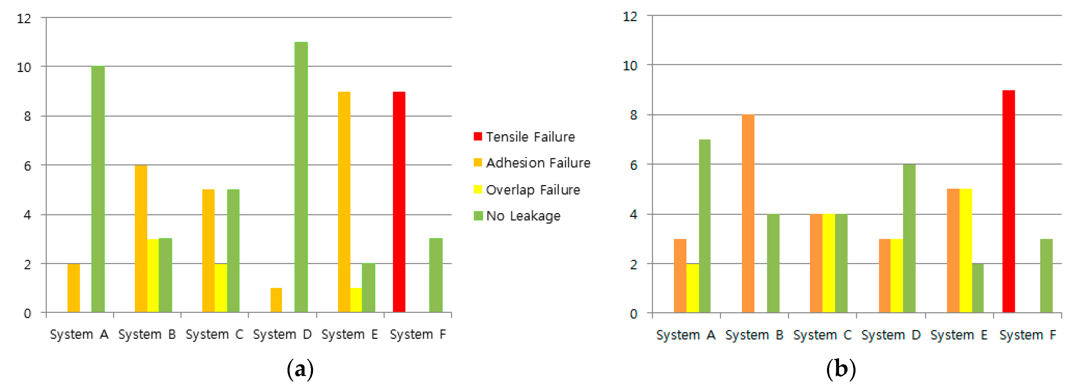
The occurrence numbers of each failure type were plotted in a bar graph. The bar graph expresses an estimation for determining the successful installation rate of each tested waterproofing membrane. The graph on the left is from dry surface conditioned specimen test results and the graph on the right is from the wet surface conditioned specimens. The occurrence rate of each failure type across different movement widths (from 2.5 mm to 10.0 mm) is compared to the number of specimens that completed the 300 displacement cycles. Refer to Figure 11 for details.
Figure 11. Failure type occurrence rates of waterproofing membrane system types; (a) dry surface installed specimen results; (b) wet surface installed specimen results.
Tensile failure of waterproofing membranes shows a clear connection between membrane durability and concrete joint load behavior. For adhesion and overlap failures, the cause could be low material quality and/or poor workmanship. In the case of systems A and D, some of the specimens were able to withstand all 300 cycles of movement for all movement widths for both surface conditions. This indicates that the membranes meet the bar for below-grade waterproofing construction. The occurrence rates of specific failure types in dry surface conditioning ((a) in Figure 11) and wet surface conditioning ((b) in Figure 11) were compared. It was clear from the occurrence rate of overlap failure (OF) and adhesion failure (AF) that the humidity affected the material adhesion on mortar surfaces. For wet surface conditioning, seven specimens for System A and six specimens for System D were able to complete the 300-cycle regime. This suggests that the respective systems may have adequate wet surface adhesion properties, but also suggests that workmanship planning and/or adhesion property on a wet surface could still be improved.
Based on the results outlined above, a decisive evaluation of the tested waterproofing membranes cannot be made. The above graph is designed to only introduce the model. It is expected that with repeated testing over a larger sample pool, more reliable data can be produced in the future and assessing the workability of waterproofing membranes will become feasible with this test method.

6. Conclusions

  • The results of the test method show that a more accurate evaluation of waterproofing membranes is possible for below-grade construction. Out of the possible load modes and exposure conditions of the below-grade construction environment, concrete joint displacement and concrete surface humidity were particularly focused on as part of the evaluation criteria.
  • Future applications of this test method should be designed to accommodate a larger range of parameters such as movement speed, cycle number, joint displacement width, and humidity level.
  • To reduce reliance on visual inspection, a more accurate and non-destructive leakage cause analysis method is currently being developed. Many improvements are needed before this test method can be officially standardized.

Acknowledgments

This research was supported by a grant (16RERP-B082204-03) from the Residential Environment Research Program Funded by the Ministry of Land, Infrastructure, and Transport of the South Korean government.

Author Contributions

Sangkeun Oh and Jaeyoung Song conceived and designed the experiments; Kyuhwan Oh and Jaeyoung Song performed the experiments; Byoungil Kim, Kyuhwan Oh and Jaeyoung Song analyzed the data; Jaeyoung Song wrote the paper.

Conflicts of Interest

The authors declare no conflict of interest. The founding sponsors had no role in the design of the study; in the collection, analyses, or interpretation of data; in the writing of the manuscript, and in the decision to publish the results.

Abbreviations

AFAdhesion Failure
AIWAustralian Institute of Waterproofing
ASAustralian Standards
ASTMAmerican Standards for Test Methods
GBGuo Biao
JISJapanese Industrial Standards
KCSKorean Construction Specification
KSKorean Industrial Standards
JSCEJapanese Society of Civil Engineers
NLNo Leakage
OFOverlap Failure
TFTensile Failure
UTMUniversal Testing Machine

References

  1. Kim, S.Y.; Oh, S.K.; Kim, B.I. Artificial-Crack-Behavior Test Evaluation of the Water-Leakage Repair Materials Used for the Repair of Water-Leakage Cracks in Concrete Structures. Appl. Sci. 2016, 6, 253. [Google Scholar] [CrossRef]
  2. Oh, S.K. Test Method of Waterproofing System for Safety of Water Leakage and Waterproofing on the Underground Structure; Facility Safety: Seoul, Korea, 2005; pp. 64–77. [Google Scholar]
  3. Oh, S.K.; Kwak, K.S.; Choi, S.M.; Kwon, S.W. Improvement of Selection System of Waterproofing Method for Concrete Structure. J. Korea Inst. Build. Constr. 2007, 7, 99–106. [Google Scholar] [CrossRef]
  4. Kunieda, M.; Rokugo, K. Recent Progress of HPFRCC in Japan—Required Performance and Applications. J. Adv. Concr. Technol. 2006, 4, 19–33. [Google Scholar] [CrossRef]
  5. Ministry of Land, Transport and Maritime Affairs. KCS 41 40 01: Standard Specification on Waterproofing Construction; Architectural Institute of Korea: Seoul, Korea, 2016.
  6. Emmons, P.H. Concrete Repair and Maintenance Illustrated; R.S. Means Company: Los Angeles, CA, USA, 1994; p. 30. [Google Scholar]
  7. Oh, S.K.; Choi, S.Y.; Kim, S.Y.; Choi, S.M. A Study on the Characteristic of Responsiveness to the Movement by Construction Method Types of Exterior Wall Waterproof to Applied in Underground Concrete Structures. J. Korea Constr. Inst. 2014, 5, 903–904. [Google Scholar]
  8. BK Institute of Technology. Proposal on Composite Waterproofing Method Evaluation Method; Seoul National University of Science and Technology, Construction Technology Research Center: Seoul, Korea, 2016; pp. 40–43. [Google Scholar]
  9. Chungwoo Media. Guide to Design and Construction for Architectural Water Proofing System; Chungwoo Media Co., Ltd.: Seoul, Korea, 1992; pp. 33–44. [Google Scholar]
  10. Chang, S.-M.; Choi, S.M.; Oh, S.-K. Analysis of the temperature-humidity changing characteristics by the applying type of the waterproofing methods. Adv. Mater. Sci. Eng. 2015, 2015, 959502. [Google Scholar] [CrossRef]
  11. Lee, K.W.; Heo, T.S.; Yang, S.B. Review on the Proper Waterproofing Methods and Waterproof Agents for Underground Structures under Chloride Attack Environment in Incheon International Airport; Yoo Shin Engineering Corporation: Seoul, Korea, 2004; pp. 181–206. [Google Scholar]
  12. Kim, J.S.; Oh, S.K. An Experimental Study on the Non-Exposure Composite Waterproofing Method Used Adhesion Liquid and Sheet Integrate Waterproofing Material. Available online: http://www.riss.kr/link?id=T11194834 (accessed on 12 June 2017).
Article Metrics

Citations

Article Access Statistics

Multiple requests from the same IP address are counted as one view.