Article

Analytical Solution for Interference Fit for Multi-Layer Thick-Walled Cylinders and the Application in Crankshaft Bearing Design

Institute for Aero-Engine, School of Aerospace Engineering, Tsinghua University, Beijing 100084, China
*
Author to whom correspondence should be addressed.
Appl. Sci. 2016, 6(6), 167; https://doi.org/10.3390/app6060167
Submission received: 4 April 2016 / Revised: 16 May 2016 / Accepted: 25 May 2016 / Published: 2 June 2016

Abstract

:
Interference fit is an important contact mode used for torque transmission existing widely in engineering design. To prevent trackslip, a certain magnitude of interference has to be ensured; meanwhile, the interference needs to be controlled to avoid failure of the mechanical components caused by high assembly stress. The finite element method (FEM) can be used to analyze the stress, while the computational cost of FEM involving nonlinear contact algorithm is relatively high, and likely to come across low precision and convergence problems. Therefore, a rapid and accurate analytical method for estimation is of vital need, especially for the initial design stage when the parameters vary in a large range. In this study, an analytical method to calculate the contact pressure and stress between multi-layer thick-walled cylinders (MLTWC) with multi-contact pairs and temperature-raising effect is proposed, and evaluated by FEM. The analytical solution of the interference for tri-layer thick-walled cylinders is applied to the design of engine crankshaft bearing. The results indicate that the analytical method presented in this study can reduce complexity of MLTWC problems and improve the computational efficiency. It is well suited to be used for the calculation model of parameter optimization in early design.

Graphical Abstract

1. Introduction

Key pins and spline are commonly used as the connect device to transmit torque from transmission shaft to gear, pulley, belt pulley and the chain wheel. Besides, the torque can also be transferred by interference fit [1,2] with lower costs, since no connecting devices, such as keyway, pin hole and spline tooth, are in need. In addition, interference fit has the advantages of high bearing capacity, and able to withstand composite loads [3,4], and has been widely applied in heavy machinery, ship engine, general machinery and engines [1,5,6,7], such as the contacts between the main bearing seat and the engine body, the engine bearing liner and the camshaft bearing seat, the cam and the hollow camshaft and so on.
In interference fit, the assembly bore of gear or sprocket is smaller than the axle diameter, and the transmission device is usually set on the shaft by compress fit or shrinkage fit [8,9]. Design of the interference is the crux of the matter, which determines the mechanical state in the connection and significantly affects the life of the fretting wear and connection [10,11]. The application of interference fit on transferring torque involves complex fits among multi-coaxial components, the stress calculation of which is relatively complicated [12]. FEM can be used to analyze the distribution and concentration of stress [8,11,13,14,15,16], while the computational cost of FEM involving contact algorithm is relatively high [9,17], and likely to come across low precision and convergence problems [18]. Due to the complexity and high cost of the modeling and optimization of the FEM [19,20], the early design of mechanical products often relies on the experience of the designers to set some key parameters, such as the interference in MLTWC problems, which is a simplification of the interference fit problems in engineering machinery [5]. FEM is in most cases used for the later design to do finer optimization [9,21]. Some rapid but accurate analytical methods are in need for the early design.
Under the hypothesis of the same axial length for the multi-layer thick-walled cylinders, the theoretical pressure are constant on the whole contacting surface; in contrast, if the shaft extends beyond the hub there is a stress concentration occurring at the extremities of the contact zone [22], which can be evaluated by performing numerical investigations, such as finite element analysis. The above stress concentration phenomenon can be hardly presented by regular theoretical solution based on Lamé’s solution for the thick-walled cylinders. Past theoretical studies also only concern the stress distributions away from the region of stress concentration. For instant, Croccolo and Vincenzl [23] provided a mathematical model that is applicable to a system of n axial symmetric elements, made of different materials, eventually coupled together with a radial interference and that can rotate at a given angular velocity.
In this study, a general analysis method for MLTWC with multi-contact pairs and temperature-raising effect is developed according to the solution from elastic theory of axisymmetric thick-walled cylinder [24]. A full set of analytical solution of the MLTWC problem, including the contact pressure and stress analysis solutions is derived. Compared with previous research, this study proposes interference solutions for MLTWC from a perspective closer to the engineering design, and establishes the relations between dimensional tolerance and the reaction torque bearable for the interference. Proceeding from bi-layer and tri-layer cylinders, the theoretical solutions are promoted to a general form, taking temperature effect into account. A stiffness reduction factor is also introduced to describe the geometric effects of irregular thick-walled cylinders. Its consistency with the results from the sophisticated FEM is verified using the instances of bi-layer and tri-layer thick-walled cylinders. The analytical solution of the MLTWC problem is finally applied to design a diesel engine crankshaft bearing support system. The calculation and design is rapidly accomplished with comparable accuracy to FEM. Compared with FEM, there is no complex modeling nor costly calculation is in need for analytical method to get results with comparative accuracy. In addition, the analytic method is able to avoid the loss of accuracy in FEM resulting from nonlinearity, and it is well suited for calculation model of parameter optimization in early design. All the calculation in this study can be easily transformed into executable computation procedure, providing great convenience for engineering application.

2. Analytical Solution of Multiple Contact Pairs for the MLTWC

2.1. Interference Quantity Design of MLTWC

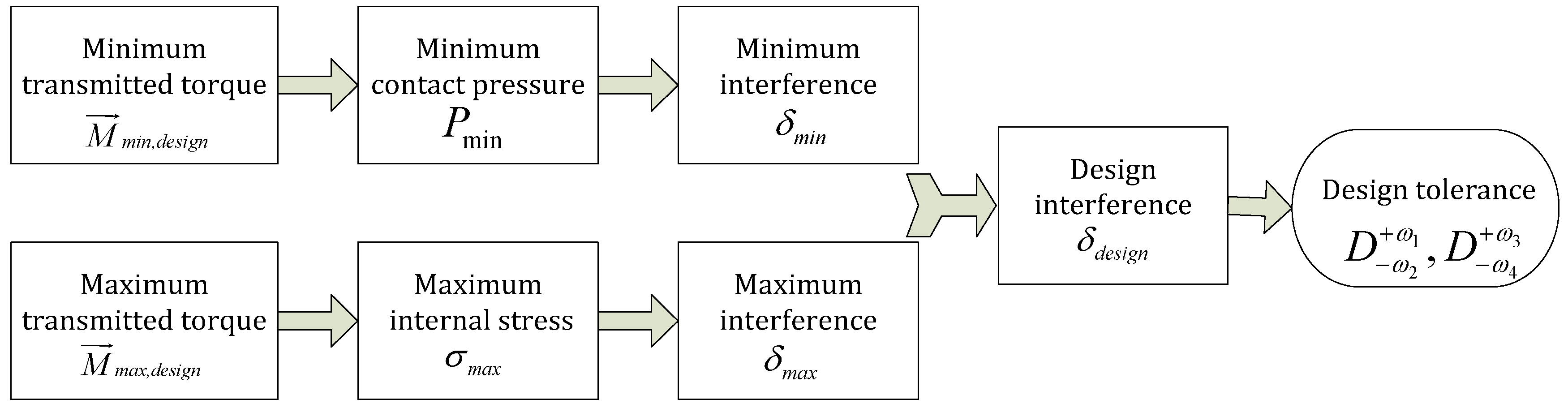
Certain interference has to be assured to prevent interference surface skid in mechanical transmission device. Meanwhile, the interference cannot be too big to avoid that the component stress falls into plastic zone and lose efficacy. Therefore, the size and tolerance of components must be designed in a reasonable range to realize a befitting interference quantity and thus the effective torque transmission.
The designed transmission torque M d e s i g n can be determined according to design requirements, which is the maximum torque that can be transmitted by the interference surfaces. The actual maximum torque needs to be larger than the designed transmission torque by a rational interference quantity, i.e., M i > M d e s i g n , i . There exists simple quantitative relationships between contact pressure P and the actual maximum torque M , i.e., M = g ( P , μ , S , R ) , here, μ , S , R represents static friction coefficient, contact area and radius of the contact face, respectively. Thus, the relationship between the interference δ and the maximum transmission torque M can be found if the quantitative description of δ and P is determined. The lower limit of the interference quantity δ m i n can be determined by the designed torque.
Excessive interference leads to such high contact pressure that there will be stress concentration inside the components. If the stress exceeds the plastic yield stress, i.e., σ m a x , i > σ s , i , the MLTWC loses efficacy due to unrecoverable local deformation. Hence, there exists an upper limit δ m a x resulting from the limit of the maximum stress. Figure 1 shows the calculation principle for interference.

2.2. Relationships between Interference and Tolerance

Suppose the axial diameter is D ω 2 + ω 1 , and the bore diameter is D ω 4 + ω 3 , where D is diameter, and superscript + ω 1   and   + ω 3 represent ecart superieur, and subscript ω 2   and   ω 4 represent ecart inferieur. There exists relationship between maximum interference δ m a x and the tolerance for a certain pair of interference fit, as shown in Equation (1):
δ m a x = 0.5 · ( ω 1 + ω 4 )
The minimum interference δ m i n also has relationship with the tolerance, as in Equation (2):
δ m i n = 0.5 · ( ω 2 ω 3 )
The deviation value of axis and bore in the interference pair can be totally determined with the given tolerance zone, i.e., the value of ( ω 1 + ω 2 ) and ( ω 3 + ω 4 ) .

2.3. Relationships between Interference and Temperature

The interference fit for torque transmission often works within certain temperature range. The contact pressure changes when the temperature changes if the coefficients of linear expansion of the contacted pair disagree, and leads to sliding failure. Therefore, the temperature effect has to be taken into account when designing the tolerance system of the MLTWC. Suppose the interference of the contact surface is δ 0 , and the working temperature is Δ T higher than the design temperature. If the linear expansion coefficient of inner cylinder wall is larger than that of outer cylinder wall, the interference increases; otherwise, the interference decreases. The relationship between the interference and the temperature rise is shown in Equation (3),
δ = δ 0 + δ T = δ 0 + ( α i α o ) × R × Δ T
where δ T is interference change resulting from temperature rise; α i and α o represent the coefficients of inner and outer cylinder walls, respectively; and R is the radius at the contact surface.

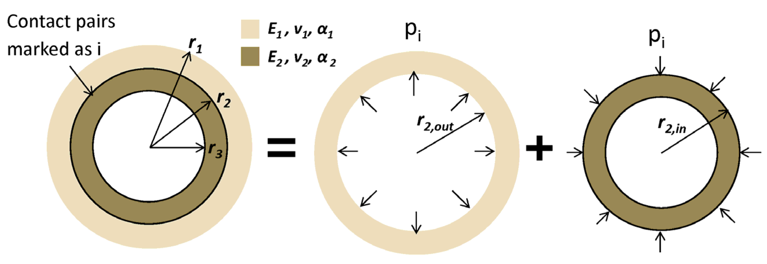
2.4. Analytical Solution of Bi-layer Thick-walled Cylinders

The left subgraph in Figure 2 describes the interference problem of bi-layer thick-walled cylinders. Within small elastic deformation, such problems satisfy superposition principle, and can be decomposed into two independent space axisymmetric problems of thick-walled cylinder, as shown in right side of the equal sign in 
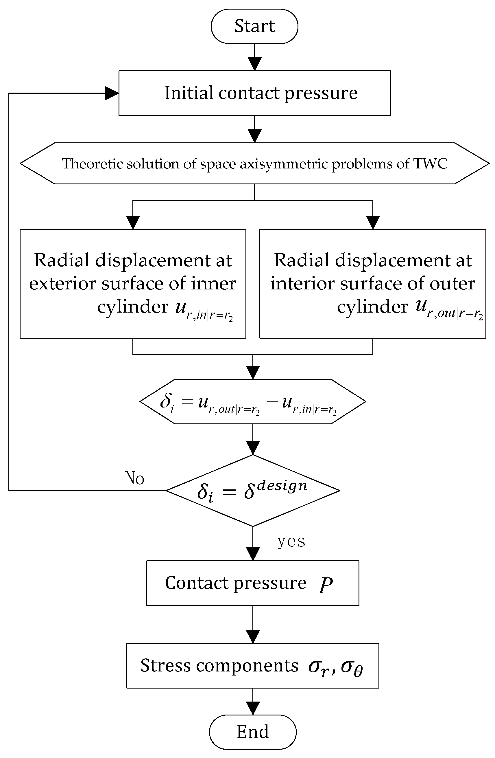
Figure 2. The overall calculation process of interference algorithm for BTC is shown in the flow diagram, Figure 3.
The thick-walled cylinder with inner and outer radius of r2,out and r1 respectively as shown in Figure 2 is under uniform internal pressure Pi, and there is no external pressure. The Young modulus of this cylinder is E1; its Poisson’s ratio is v1, and the thermal linear expansion coefficient is α1. According to the theoretic solution of space axisymmetric problems of thick-walled cylinder, the radial displacement at the inner surface of this cylinder can be expressed as:
u r ,   o u t | r = r 2 = r 2 , o u t 3 P i ( 1 v 1 ) E 1 ( r 1 2 r 2 , o u t 2 ) + r 1 2 r 2 , o u t P i ( 1 + v 1 ) E 1 ( r 1 2 r 2 , o u t 2 )
where the subscript r in u r ,   o u t | r = r 2 represents radial direction, and the subscript out indicates outside of the contact surface.
The thick-walled cylinder with inner and outer radius of r3 and r2,in respectively as shown in Figure 2 is under uniform external pressure Pi, and there is no internal pressure. The Young modulus of this cylinder is E2; its Poisson's ratio is v2, and the thermal linear expansion coefficient is α2. According to the theoretic solution of space axisymmetric problems of thick-walled cylinder, the radial displacement at the outer surface of this cylinder can be expressed as:
u r ,   i n | r = r 2 = r 2 , i n 3 P i ( 1 v 2 ) E 2 ( r 2 , i n 2 r 3 2 ) r 2 , i n r 3 2 P i ( 1 + v 2 ) E 2 ( r 2 , i n 2 r 3 2 )
where the subscript r in u r ,   i n | r = r 2 represents radial direction, and the subscript in indicates inside of the contact surface.
Assembling two concentric thick-walled cylinders together, r2,out is slightly smaller than r2,in, and the difference between them is the interference δi as shown in Equation (6), which determines the displacement coordination between the inner and outer cylinders on the contact surface.
δ i = u r , o u t | r = r 2 u r , i n | r = r 2
The displacement along the radial direction is set to be positive, otherwise it is negative.
Derived from the displacement coordination in Equation (6), the contact pressure Pi can be obtained as shown in Equation (7):
P i = δ i r 2 , o u t ( r 2 , o u t 2 ( 1 + v 1 ) + r 1 2 ( 1 + v 1 ) ) E 1 ( r 1 2 r 2 , o u t 2 ) + r 2 , i n ( r 2 , i n 2 ( 1 + v 2 ) r 3 2 ( 1 + v 2 ) ) E 2 ( r 3 2 r 2 , i n 2 )
Approximately regarding r2,out is equal to r2,in, and denoting both of them as r2, the simplified pressure is expressed in Equation (8).
P i = δ i r 2 ( r 2 2 ( 1 + v 1 ) E 1 ( r 1 2 + r 2 2 ) + r 1 2 ( 1 + v 1 ) E 1 ( r 1 2 r 2 2 ) r 2 2 ( 1 + v 2 ) E 2 ( r 2 2 r 3 2 ) + r 3 2 ( 1 + v 2 ) E 2 ( r 2 2 r 3 2 ) )
Few coaxial components in contact can be found in actual structure as flawless thick-walled cylinders as in theoretical assumptions. Various local reinforced or lightened structures are added. Therefore, the actual material stiffness needs to be discounted according to the volume fraction of the material, which is defined as the percentage of the actual component volume to the volume of an ideal thick-walled cylinder taking component outer contour as the boundary. Such volume fraction is regarded as the stiffness discount factor ϕ , so that the contact pressure between the bi-layer thick-walled cylinders is:
P = δ r 2 ( r 2 2 ( 1 + v 1 ) E 1 φ 1 ( r 1 2 + r 2 2 ) + r 1 2 ( 1 + v 1 ) E 1 φ 1 ( r 1 2 r 2 2 ) r 2 2 ( 1 + v 2 ) E 2 φ 2 ( r 2 2 r 3 2 ) + r 3 2 ( 1 + v 2 ) E 2 φ 2 ( r 2 2 r 3 2 ) )
Equations (8) and (9) indicate that the contact pressure is in direct proportion to the interference, the proportionality coefficient of which depends on the geometrical characteristic and material property of the contact pair. Material with larger Young modulus has larger proportionality coefficient, resulting in higher contact pressure.
Given the contact pressure of the bi-layer cylinders P i , the stress of the inner and outer cylinder are shown in Equations (10) and (11), respectively, from the theoretic solution of space axisymmetric problems of thick-walled cylinder.
Stress of the inner cylinder,
{ σ r , i n = P i r 2 2 r 2 2 r 3 2 + 1 r 2 r 3 2 r 2 2 P i r 2 2 r 3 2 σ θ , i n = P i r 2 2 r 2 2 r 3 2 1 r 2 r 3 2 r 2 2 P i r 2 2 r 3 2 σ z , o u t = 0 τ z r , o u t = 0
Stress of the outer cylinder,
{ σ r , o u t = P i r 2 2 r 1 2 r 2 2 1 r 2 r 2 2 r 1 2 P i r 1 2 r 2 2 σ θ , o u t = P i r 2 2 r 1 2 r 2 2 + 1 r 2 r 2 2 r 1 2 P i r 1 2 r 2 2 σ z , o u t = 0 τ z r , o u t = 0

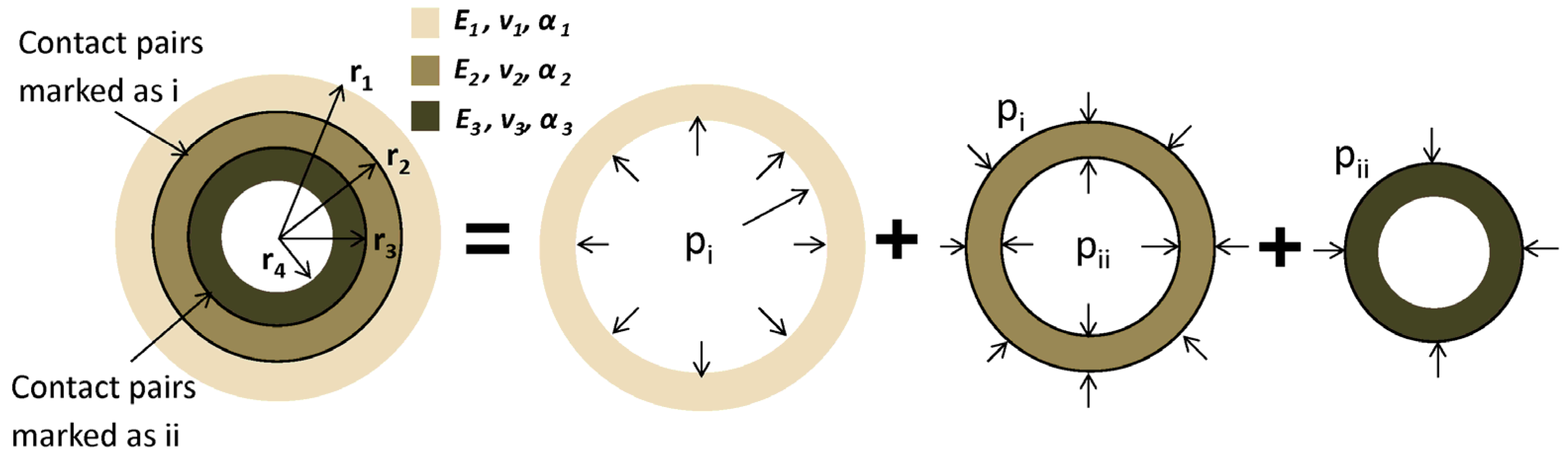
2.5. Analytical Solution of Tri-layer Thick-walled Cylinders

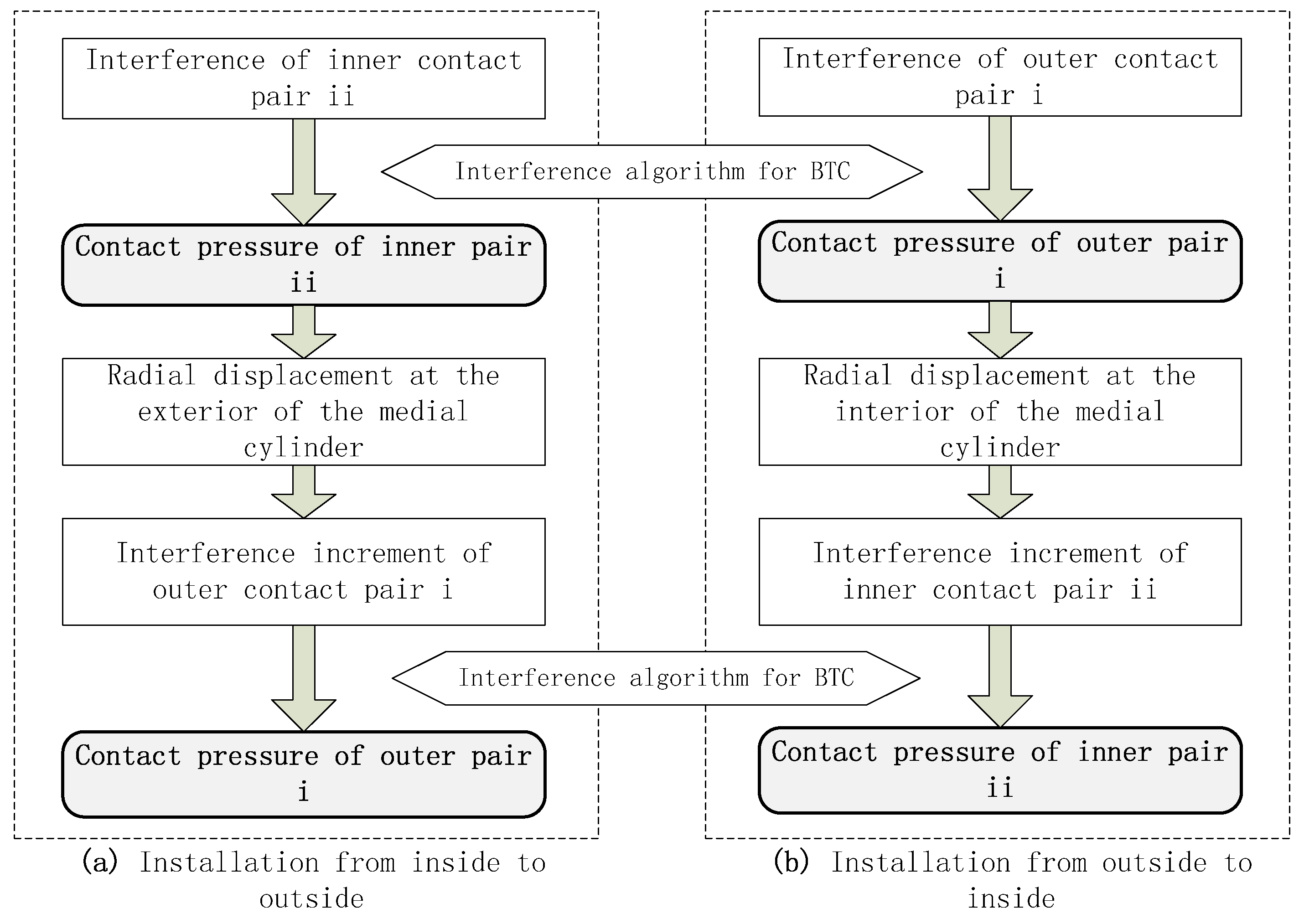
Three nested thick-walled cylinders go with one another for interference. The calculation flow for contact pressure and interference of tri-layer thick-walled cylinders with different assembly sequence is shown in Figure 4. 
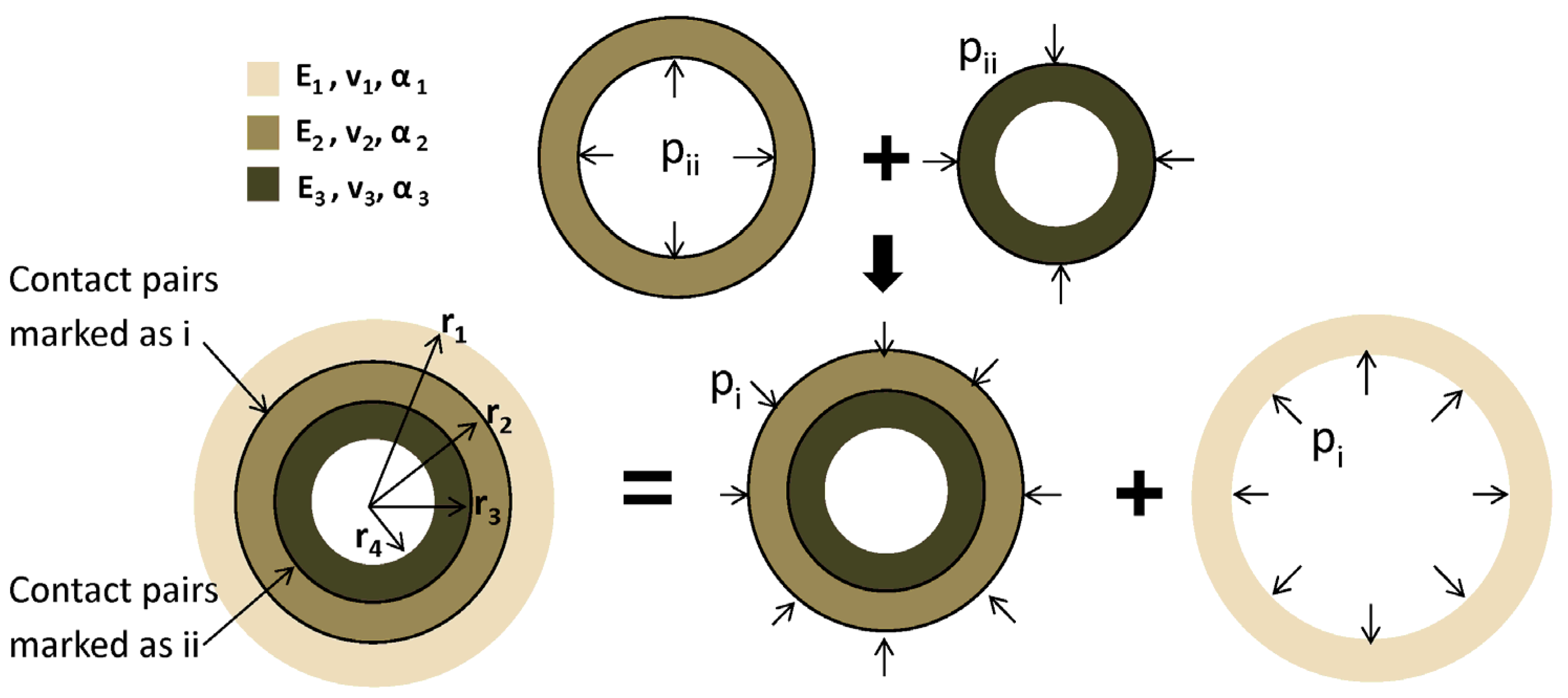
Figure 5 shows the superposition principle of tri-layer thick-walled cylinders installed from inside to outside; while Figure 6 indicates the installation from outside to inside. Figure 7 presents the installation when the contact pairs are formed simultaneously. From Figure 5, Figure 6 and Figure 7, different colors represent different coaxial thick-walled cylinders with the material parameters of E1, v1, α1; E2, v2, α2; and E3, v3, α3, respectively, wherein E is the Young's modulus, v the Poisson ratio, and α the thermal linear expansion coefficient. The outer cylinder in light gray and the medial cylinder in gray form a contact pair at radius r2, denoted as contact pair i, and the variable relevant to this pair are represented with the subscript i. In the same manner, the contact pair composed of the medial cylinder in gray and the inner cylinder in dark gray radius r3 is represent by ii.

2.5.1. Installation from Inside to Outside

The installation is split into two steps: the inner contact pair ii goes first, and then the outer contact pair i is assembled. To calculate contact pressure, the two pairs are analyzed separately, and then the results of them are superposed on the basis of superposition principle, as shown in Figure 5.
The interference of the inner contact pair δii can be solved by Equation (3). Using the simplified Formula (8) to calculate the contact pressure between two thick-walled cylinders, the contact pressure of the inner pair ii is derived as:
P i i = δ i i r 3 ( r 3 2 ( 1 + v 2 ) E 2 ( r 2 2 + r 3 2 ) + r 2 2 ( 1 + v 2 ) E 2 ( r 2 2 r 3 2 ) r 3 2 ( 1 + v 3 ) E 3 ( r 3 2 r 4 2 ) + r 4 2 ( 1 + v 3 ) E 3 ( r 3 2 r 4 2 ) )
According to the solution of the thick-walled cylinder axisymmetric problem, the contact pair ii will lead to a radial displacement at the exterior of the medial cylinder, as shown in Equation (13).
u r | r = r 2 = 2 P i i r 2 r 3 2 E 2 ( r 2 2 r 3 2 )
Such radial displacement results in an increase of the interference of the outer contact pair i. Denoting this increase as δ c : i i i , the value of which is equal to u r | r = r 2 . δ c : i i i indicates the monodirectional effect from contact pair ii to i. Based on the Formula (3), the interference δ i of contact pair i should be expressed as:
δ i = δ 0 + δ T + δ c : i i i
Applying the simplified computational formula (8) to calculate the contact pressure Pi of the contact pair i, Equation (15) can be derived:
P i = δ 0 + δ T + 2 r 2 r 3 2 E 2 ( r 2 2 r 3 2 ) δ ii r 3 ( r 3 2 ( 1+ v 2 ) E 2 ( r 2 2 + r 3 2 ) + r 2 2 ( 1+ v 2 ) E 2 ( r 2 2 r 3 2 ) r 3 2 ( 1+ v 3 ) E 3 ( r 3 2 r 4 2 ) + r 4 2 ( 1+ v 3 ) E 3 ( r 3 2 r 4 2 ) ) r 2 ( r 2 2 ( 1+ v 1 ) E 1 ( r 1 2 + r 2 2 ) + r 1 2 ( 1+ v 1 ) E 1 ( r 1 2 r 2 2 ) r 2 2 ( 1+ v 2 ) E 2 ( r 2 2 r 3 2 ) + r 3 2 ( 1+ v 2 ) E 2 ( r 2 2 r 3 2 ) )
Such calculation is in accordance with the component installation from inside to outside. The calculated contact pressure of the inner contact pair ii is not the final result. The outer contact pair i increases the material stiffness of the exterior of the inner contact pair, and thus increases the contact pressure of the inner contact pair. The calculated contact pressure of the inner pair is smaller than the actual value. Besides, the calculation of the contact pressure of the outer pair also does not consider the impact of the innermost material stiffness, as a result, the calculated value is as well smaller than the actual value.

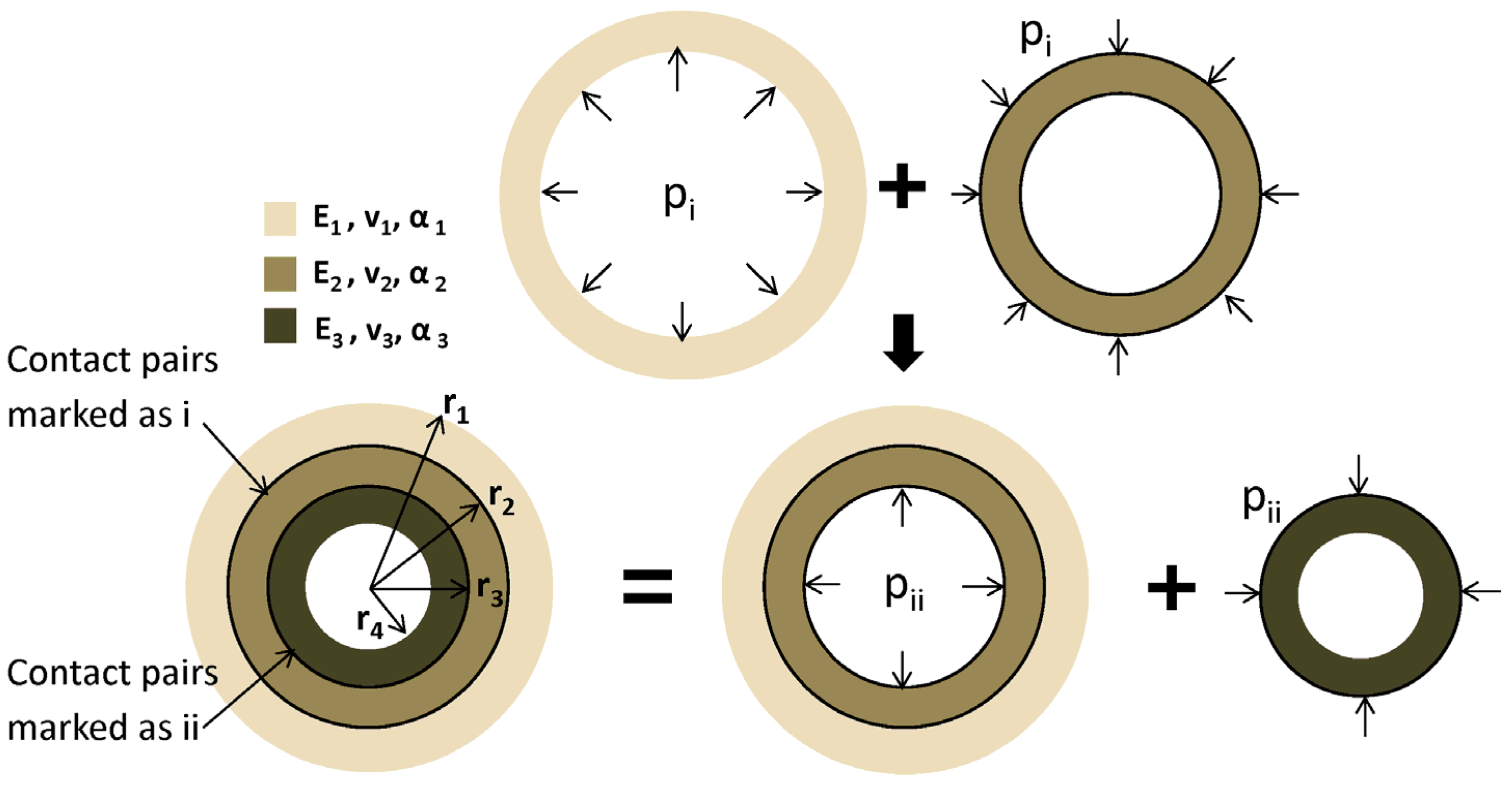
2.5.2. Installation from Outside to Inside

This time, the outer contact pair i is assembled firstly, and then the inner contact pair i is fit. Similar with the calculation in Section 2.5.1, the superposition principle of the contact pressure of the two contact pairs is shown in Figure 6.
The interference of the outer contact pair δi can be solved by Equation (3). Using Formula (8) to calculate the contact pressure between two thick-walled cylinders, the contact pressure of the outer pair i is derived as:
P i = δ i r 2 ( r 2 2 ( 1 + v 1 ) E 1 ( r 1 2 + r 2 2 ) + r 1 2 ( 1 + v 1 ) E 1 ( r 1 2 r 2 2 ) r 2 2 ( 1 + v 2 ) E 2 ( r 2 2 r 3 2 ) + r 3 2 ( 1 + v 2 ) E 2 ( r 2 2 r 3 2 ) )
The radial displacement at the interior of the medial cylinder resulting from the outer contact pair i is:
u r | r = r 3 = 2 P i r 3 r 2 2 E 2 ( r 2 2 r 3 2 )
This displacement leads to an interference increase of inner contact pair ii, denoted as   δ c : i i i with the value of u r | r = r 3 . δ c : i i i indicates the monodirectional effect from contact pair i to ii, and the interference δ i i of contact pair ii is:
δ i i = δ 0 + δ T + δ c : i i i
The contact pressure Pii of the contact pair ii is calculated by Formula (8):
P ii = δ 0 + δ T + 2 r 3 r 2 2 E 2 ( r 2 2 r 3 2 ) δ i r 2 ( r 2 2 ( 1+ v 1 ) E 1 ( r 1 2 + r 2 2 ) + r 1 2 ( 1+ v 1 ) E 1 ( r 1 2 r 2 2 ) r 2 2 ( 1+ v 2 ) E 2 ( r 2 2 r 3 2 ) + r 3 2 ( 1+ v 2 ) E 2 ( r 2 2 r 3 2 ) ) r 3 ( r 3 2 ( 1+ v 2 ) E 2 ( r 2 2 + r 3 2 ) + r 2 2 ( 1+ v 2 ) E 2 ( r 2 2 r 3 2 ) r 3 2 ( 1+ v 3 ) E 3 ( r 3 2 r 4 2 ) + r 4 2 ( 1+ v 3 ) E 3 ( r 3 2 r 4 2 ) )
The calculation above is in accordance with the component installation from outside to inside. The calculated contact pressure of the outer contact pair i is smaller than the actual value, since the existence of the inner contact pair enlarges the interior material stiffness of the outer contact pair, and thus enlarges the contact pressure of the outer pair. The calculation of the contact pressure of the inner pair also does not take the impact of the outermost material stiffness into account, and the calculated value is thus smaller than the actual value too.

2.5.3. Holistic Coupling Analysis

Within a small elastic deformation range, the interference problems of tri-layer thick-walled cylinders satisfy the principle of superposition, which can be divided into three separate thick-walled cylinders problems of space axially symmetry. The calculated results of these separate parts are then superposed based on the principle of superposition, as shown in Figure 7.
According to the theoretical solution of thick-walled cylinder axisymmetric problem, the radial displacement at the interior surface of the outermost cylinder u r , o u t | r = r 2 , the radial displacement at the exterior surface of the medial cylinder u r , i n | r = r 2 , the radial displacement at the interior surface of the medial cylinder u r , o u t | r = r 3 , and the radial displacement at the exterior surface of the inner cylinder u r , i n | r = r 3 can be derived, as shown in Equations (20)–(23).
u r , o u t | r = r 2 = P i r 2 3 ( 1 υ 1 ) E 1 ( r 1 2 r 2 2 ) + P i r 1 2 r 2 ( 1 + υ 1 ) E 1 ( r 1 2 r 2 2 )
u r , i n | r = r 2 = ( P i r 2 3 + P i i r 2 r 3 2 ) ( 1 υ 2 ) E 2 ( r 2 2 r 3 2 ) + ( P i + P ii ) r 2 r 3 2 ( 1 + υ 2 ) E 2 ( r 2 2 r 3 2 )
u r , o u t | r = r 3 = ( P i r 2 2 r 3 + P i i r 3 3 ) ( 1 υ 2 ) E 2 ( r 2 2 r 3 2 ) + ( P i + P i i ) r 2 2 r 3 ( 1 + υ 2 ) E 2 ( r 2 2 r 3 2 )
u r , i n | r = r 3 = P i i r 3 3 ( 1 υ 3 ) E 3 ( r 3 2 r 4 2 ) P i i r 3 r 4 2 ( 1 + υ 3 ) E 3 ( r 3 2 r 4 2 )
The interference of the inner and outer contact pair of the nested thick-walled cylinders determines the displacement coordination of the corresponding cylinders on the contact surface.
u r , o u t | r = r 2 u r , i n | r = r 2 = δ i
u r , o u t | r = r 3 u r , i n | r = r 3 = δ i i
Substituting the radial displacement in Equations (20)–(23) into displacement coordination in Equations (24) and (25), the contact pressure can be derived.

2.5.4. Stress Analysis

Given the contact pressure P i and P i i of the tri-layer cylinders, the stress of the inner, medium and outer cylinder are shown in Equations (26)–(28), respectively, from the theoretic solution of space axisymmetric problems of thick-walled cylinder.
Stress of the inner cylinder,
{ σ r , i n = P i i r 3 2 r 3 2 r 4 2 + 1 r 2 r 4 2 r 3 2 P i i r 3 2 r 4 2 σ θ , i n = P i i r 3 2 r 3 2 r 4 2 1 r 2 r 4 2 r 3 2 P i i r 3 2 r 4 2 σ z , i n = 0 τ z r , i n = 0
Stress of the medium cylinder,
{ σ r,medium = P ii r 3 2 P i r 2 2 r 2 2 r 3 2 + 1 r 2 r 3 2 r 2 2 ( P i P ii ) r 2 2 r 3 2 σ θ,medium = P ii r 3 2 P i r 2 2 r 2 2 r 3 2 1 r 2 r 3 2 r 2 2 ( P i P ii ) r 2 2 r 3 2                       σ z,medium =0 τ zr,medium =0
Stress of the outer cylinder,
{ σ r , o u t = P i r 2 2 r 1 2 r 2 2 1 r 2 r 2 2 r 1 2 P i r 1 2 r 2 2 σ θ , o u t = P i r 2 2 r 1 2 r 2 2 + 1 r 2 r 2 2 r 1 2 P i r 1 2 r 2 2 σ z , o u t = 0 τ z r , o u t = 0

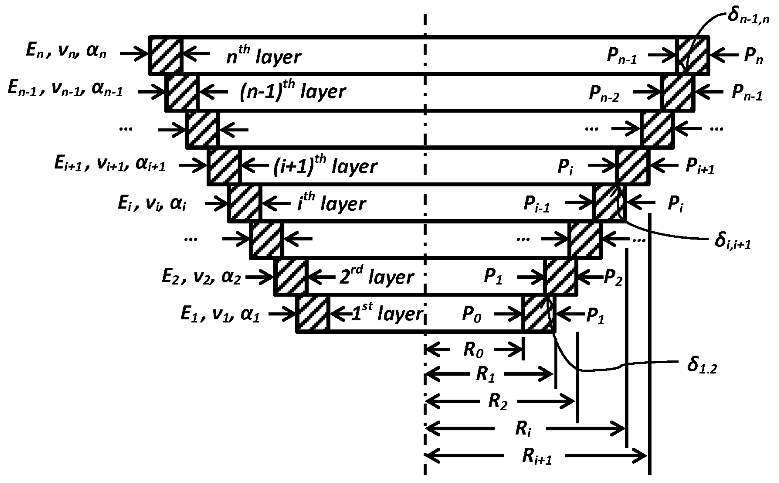
2.6. General Analytical Solution of Multiple Contact Pairs for the MLTWC

Without loss of generality, the interference fit of a MLTWC system with n thick-walled cylinders is studied, as shown in 
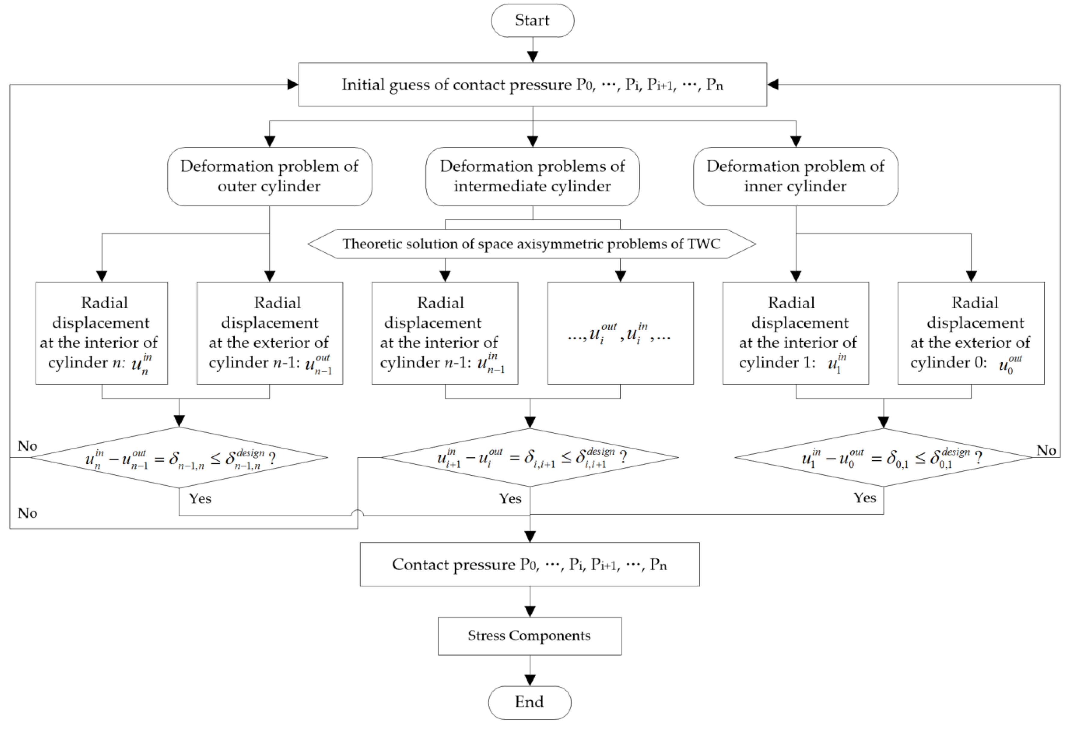
Figure 8. A holistic coupling method is developed to analyze the interference of MLTWC. The calculation flow diagram for the interference algorithm without consideration of assembly sequence is illustrated in Figure 9.
The interference fit between the ith layer and (i + 1)th layer of the MLTWC is shown in Figure 8, which is composed of the outer surface of the ith thick-wall cylinder and the inner surface of the (i + 1)th cylinder. The radial displacement u of these two surface needs to satisfy the displacement coordination described in Equation (29), so that there is no gap or penetration between these two surfaces.
u i + 1 i n u i o u t = δ i , i + 1 ( i = 1 , 2 , , n 1 )
where the superscript represents the inner and outer surface, respectively.
Under the hypothesis of small elastic deformation, the interference fit of n MLTWC satisfies superposition principle, which can be equivalent to n axisymmetric thick-wall cylinders with uniformly distributed interior and exterior pressure. According to the elastic theory solution, the radial displacement of the outer surface of the ith cylinder is shown in Equation (30).
u i o u t = R i [ P i 1 ( R i 1 δ i 1 , i ) 2 P i R i 2 ] ( 1 υ i ) E i ( R i 2 ( R i 1 δ i 1 , i ) 2 ) + ( P i 1 P i ) ( R i 1 δ i 1 , i ) 2 R i ( 1 + υ i ) E i ( R i 2 ( R i 1 δ i 1 , i ) 2 )
Since δ i 1 , i is small compared to R i 1 , Equation (30) can be simplified as in Equation (31).
u i o u t = R i [ P i 1 R i 1 2 P i R i 2 ] ( 1 υ i ) E i ( R i 2 R i 1 2 ) + ( P i 1 P i ) R i 1 2 R i ( 1 + υ i ) E i ( R i 2 R i 1 2 )
Similarly,
u i + 1 i n = R i ( P i R i 2 P i + 1 R i + 1 2 ) ( 1 υ i + 1 ) E i + 1 ( R i + 1 2 R i 2 ) + ( P i P i + 1 ) R i R i + 1 2 ( 1 + υ i + 1 ) E i + 1 ( R i + 1 2 R i 2 )
Put Equations (31) and (32) into Equation (29), then
δ i , i + 1 = R i ( 2 P i 1 R i 1 2 P i ( R i 2 ( 1 + υ i ) + R i 1 2 ( 1 + υ i ) ) E i ( R i 1 2 R i 2 ) + 2 P i + 1 R i + 1 2 P i ( R i 2 + R i + 1 2 ) + P i ( R i 2 R i + 1 2 ) υ i + 1 E i + 1 ( R i 2 R i + 1 2 ) )
Expand it and group terms, Equation (34) can be derived.
δ i,i+1 = 2 R i1 2 R i E i ( R i1 2 R i 2 ) P i1 +[ R i ( R i 2 + R i1 2 ) E i ( R i 2 R i1 2 ) R i υ i E i + R i ( R i+1 2 + R i 2 ) E i+1 ( R i+1 2 R i 2 ) + R i υ i+1 E i+1 ] P i + 2 R i R i+1 2 E i+1 ( R i 2 R i+1 2 ) P i+1
It can be seen from Equation (34) that P i 1 , P i , and P i + 1 all have their own contributions to δ i , i + 1 , which is determined by the parameters of material and geometrical characteristics. Represent the coefficients of P i 1 , P i , and P i + 1 in Equation (34) by S i , i 1 , S i , i , and S i , i + 1 , respectively, and Equation (34) can be rewritten as:
{          δ i,i+1 = S i,i1 P i1 + S i,i P i + S i,i+1 P i+1                S i,i1 = 2 R i1 2 R i E i ( R i1 2 R i 2 ) S i,i = R i ( R i 2 + R i1 2 ) E i ( R i 2 R i1 2 ) R i υ i E i + R i ( R i+1 2 + R i 2 ) E i+1 ( R i+1 2 R i 2 ) + R i υ i+1 E i+1              S i,i+1 = 2 R i R i+1 2 E i+1 ( R i 2 R i+1 2 ) ( i=1,2n1 )
Combining n thick-wall cylinders together, there appears n − 1 pair of interference fit, and n − 1 Equations can be established as in Equation (36).
{                 δ 1,2 = S 1,0 P 0 + S 1,1 P 1 + S 1,2 P 2 , i=1                δ 2,3 = S 2,1 P 1 + S 2,2 P 2 + S 2,3 P 3 , i=2   δ n2,n1 = S n2,n3 P n3 + S n2,n2 P n2 + S n2,n1 P n1 ,i=n2 δ n1,n = S n1,n2 P n2 + S n1,n1 P n1 + S n1,n P n ,i=n 1
Rewrite Equation (36) to matrix form:
[ δ 1,2 δ 2,3 δ n2,n1 δ n1,n ]=[ S 1,0 S 1,1 S 1,2     S 2,1 S 2,2 S 2,3                 S n2,n3 S n2,n2 S n2,n1     S n1,n2 S n1,n1 S n1,n ][ P 0 P 1 P n1 P n ]
n − 1 values of P 1 ,   P 2 , , P n 1 can be derived from Equation (37) in total.
Based on the elastic theory solution of axisymmetric thick-wall cylinders under uniformly distributed interior and exterior pressure, the principal stress of the ith thick-wall cylinder is shown in Equation (38).
{ σ r = P i1 R i1 2 P i R i 2 R i 2 R i1 2 + 1 r 2 R i1 2 R i 2 ( P i P i1 ) R i 2 R i1 2 σ θ = P i1 R i1 2 P i R i 2 R i 2 R i1 2 1 r 2 R i1 2 R i 2 ( P i P i1 ) R i 2 R i1 2                               σ z =0                                  τ zr =0
when degenerated to a contact problem between two thick-walled cylinders, assuming P 0 = P 2 = 0 , Equation (39) can be derived from Equation (37):
P 1 = δ 1 , 2 S 1 , 1 = δ 1 , 2 R 1 ( R 1 2 + R 0 2 ) E 1 ( R 1 2 R 0 2 ) R 1 v 1 E 1 + R 1 ( R 2 2 + R 1 2 ) E 2 ( R 2 2 R 1 2 ) + R 1 v 2 E 2
After simplification, it can be found that Equation (39) accords with Equation (8).
When degenerated to a contact problem of tri-layer thick-walled cylinders, assuming P 0 = P 3 = 0 , P1 and P2 can be derived from Equation (37), which accords with the results from holistic coupling analysis.
The solution of Equation (37) is the contact pressure of n-layer thick-walled cylinders, substituting which into Equation (38), the stress of the arbitrary ith layer cylinder can be derived.

3. Validation of Analytical Solution

When complicated MLTWC is degenerated to bi-layer or tri-layer thick-walled cylinders, superposition principle of elastic mechanics can be used to obtain the relationship between contact pressure and the magnitude of interference, as shown in Section 2.4 and Section 2.5.
Commercial finite element software ABAQUS (6.14, Dassault Systèmes, Boston, MA, USA, 2015) is adopted for FE modeling and analysis. Both of the bi-layer and tri-layer thick-walled cylinders FE models use 3D FE model with 20-node hexahedral element (C3D20) to discrete, the axial and circumferential degree of freedom (DOF) of the thick-walled cylinders is constrained, and the mechanical behavior of materials is described by linear elastic constitutive relationship. Grid convergence analysis was carried out before calculation.

3.1. Soluation of Bi-Layer Thick-Walled Cyliners

Taking single contact pair between bi-layer thick-walled cylinders as an example, the contact radius is 33.5 mm with interference of 28.71 μm; the outer cylinder is made of aluminum alloy with the maximum radius of 70 mm; and the inner cylinder is made of steel with the minimum radius of 31 mm.
The relative error between theoretical solution and finite element analysis solution is around 1%, as shown in Table 1. The consistency of the results from FEM and theoretical method validates the correctness of the form of the derived theoretical solution.

3.2. Soluation of Tri-Layer Thick-Walled Cyliners

For tri-layer thick-walled cylinders, the contact radius are 33.5 mm and 70 mm, respectively; the interference of both contact pairs are 28.71 μm; the outer cylinder is made of gray iron with the maximum radius of 115 mm; the medium cylinder is made of aluminum alloy; and the inner cylinder is made of steel with the minimum radius of 31 mm.
By sequence analysis method, the contact pressure of the outer contact pair can be calculated in the analysis order of inside to outside, while the contact pressure of the inner contact pair can be calculated in the analysis order of outside to inside. Thus, two-way sequential coupling calculations are needed to get the contact pressure of the two contact surfaces. It can be seen in Section 2.5.1 and Section 2.5.2 that these calculated contact pressure are the lower limits of the actual values. The example in this section shows that the contact pressure calculated by sequence analysis is 10%–20% lower than the actual value, shown in Table 2. In contrast, the holistic coupling analysis is proved to be a reliable method with high accuracy, the relative errors of which is less than ±0.6%, shown in Table 2.
The analytical method educes results consistent with FEM for both the examples of bi-layer and tri-layer thick-walled cylinders with high accuracy, as shown in Table 1 and Table 2, and which verifies the correctness of the analytical solutions. Besides, the stress on the interference contact surface derived from FEM tends to perform circumferential fluctuation, especially for the inner cylinder. In our simple example, the stress component of the nodes selected randomly on the contact surface of the inner cylinder disperses distinctly. Further numerical analysis indicates that such dispersion depends on the mesh scale, and it is caused by the numerical error in finite element discretization, which is difficult to avoid. There are no such problems with the analytical method.

4. Application in Crankshaft Bearing Design

4.1. Interference Assembly Problem of Crankshaft Bearing

The method proposed in this study is applied to the structural design of a new electronically controlled single-cylinder diesel engine. The crankshaft bearing support of this new designed engine adopts sliding mode, the support system of which is shown in Figure 10. At operating temperature, bearing sleeve, bearing block and cylinder expand freely. Interference fit is formed between the bearing sleeve and block, as well as between bearing block and cylinder bearing hole. Therefore, only appropriate assembly interference can ensure that the contact pair is able to resist certain friction torque without causing excessive assembly stress.
The material property of the components of crankshaft bearing support system is shown in Table 3.
The initial design at normal temperature (25 °C) indicates that the interference between bearing sleeve and the bearing block is 0.0825 mm, and the gap between bearing block and cylinder bearing bore is 0.025 mm. Iterative calculations around the initial design are needed to determine the allowable range of the interference, and then determine the tolerances of components. Minimum interference (i.e., the assembly interference between bearing sleeve and bearing block is minimum, and the gap between bearing block and cylinder bearing bore is maximum) corresponds to the minimum contact pressure, when it needs to be ensured that no relative rotation occurs between the contact components. Maximum interference (i.e., the assembly interference between bearing sleeve and bearing block is maximum, and the gap between bearing block and cylinder bearing bore is minimum) corresponds to the maximum contact pressure, when it needs to be ensured that no plastic yielding occurs for the contact components.

4.2. Analytic Solution Procedure

The interference between bearing sleeve and block calculated by Equation (3) at operating temperature (100 °C) is 0.0614 mm; the interference between front bearing block and cylinder bearing bore is 0.028 mm; and that between back bearing block and cylinder bearing bore is 0.037 mm.
The modulus reduction coefficients of this problem are all set to be 70% with the definition in Section 2.4. Taking the height of the cylinder as its characteristic length, the value is assigned as the diameter of the outer cylinder in tri-layer thick-walled cylinder model.
The interference fit in sliding crankshaft bearing is equivalent to a tri-layer thick-walled cylinder problem, the contact pressure of which is solved by Equations (14) and (24). The results are then substituted into Equations (26)–(28) to get the stress of each component.

4.3. FE Modeling Process

FEM software, ABAQUS, is used to model a filmatic bearing support system. The model simulates interference and thermal expansion process in sequence. The interference is realized by setting up the amount of interference in surface-to-surface contact; while the thermal expansion is implemented by assigning the expansion coefficient in material constitutive relation and setting the temperature field as predefined field.
The type and size of the element in FE model greatly affects the accuracy of the simulation. The first-order linear complete integral element is adopted instead of reduced integration to prevent hour-glassing numerical problem. The avoidance of quadratic element results from that no obvious bend condition is observed in the components and thus shear locking is less likely to occur. In order to reduce calculation error of the contact stress, regular hexahedral elements are used to discretize the area around both sides of the contact pair. Due to the irregular geometry of other regions, they are discretized by tetrahedral meshes with strong border adaptability. The element type and quantity of the components in FE model is shown in Table 4.

4.4. Comparison between Analytical Method and FEM

4.4.1. Contact Pressure

The contact pressure derived from the analytical method and FEM are compared in Table 5. As the actual structure is not a completely regular cylinder nested structure geometrically, there still exist certain errors in the computed results even though the modulus of the cylinders have been reduced. Although some differences are found comparing the two methods, they are basically at the same level, and both of them present that the contact pressure between bearing sleeve and bearing block is larger than that between bearing block and cylinder bearing bore.

4.4.2. Von Mises Stress

The von Mises stress magnitude and distribution of the interference in sliding crankshaft bearing support system under temperature loading is solved by FE method, as shown in Figure 11.
As for the FE calculation results, the non-uniform distribution of the stress on contact surface differs from analytical solutions, in which both the circumferential and axial stress of the contact surface distributes evenly. Such characteristics of the FE solution relates to the local structural features of the components in support system.
The von Mises stress distribution resulting from FE analysis indicates that for all layers of the cylinders, the von Mises stress of the inner circle is higher than that of the outer circle. This rule is also demonstrated by the analytical solution. Therefore, the von Mises stress of the inner circle of each component is paid particular attention, as shown in Table 6. For analytical solution, the obtained σ r and σ θ are principal stress components, so that the von Mises stress is equal to 0.5 r ( ( σ r σ θ ) 2 + σ r 2 + σ θ 2 ) .
Table 6 shows that on a certain contact surface, the von Mises stress obtained by FE analysis is not evenly distributed, but varies within a range, as in Figure 11. Such non-uniformity of stress distribution results from the non axial-symmetry of the actual geometry as well as the boundary conditions, and partly due to the numerical error; while the stress on contact surface derived from analytical solution is uniformly distributed, which makes the assessment of the maximum reaction torque afforded by the contact more convenient. In addition, both the FE analysis and analytical solution indicate that the radial stress on both sides of a contact is continuous, but the circumferential stress is not, nor the von Mises stress.
Based on the data in Table 6, the analytic solution of stress in different components basically falls into the scope of the FE element solution or approaches the boundary of the FE solution. After all, the analytical solution is based on ideal multi-layer cylinders interference model, which highly abstracts the real mechanical problems, especially in structural characteristics and mechanical boundary conditions. FEM is able to simulate the real mechanical model more completely. Therefore, that the FE solution can be regarded as a reference for analytical solution. Such a close approximation of the analytical solution to FE solution verifies the applicability and reliability of the analytical solutions from multi-layer cylinder interference mechanical model.

4.4.3. Computing Cost

Both the FE and analytic solutions in this study are obtained from a micro computing server with Xeon processors of 8 cores, 32 threads and 3.1 GHz main frequency, 127 GB of RAM.
It takes 1 h to complete the calculation by FE method, and the analytical method proposed in this study costs far less than 1 s. The computational resources cost by FEM is several orders of magnitude higher than that of analytical method. Thus, analytical method takes minimal computational cost to obtain an approximate result from time-consuming FEM.

5. Conclusions

The multi-layer thick-walled cylinders (MLTWC) problem is a significant class in engineering design, which mainly relies on FEM in previous studies and applications. This study starts from interference fit of bi-layer thick-walled cylinders, analyzes tri-layer cylinders, and then generalizes it to MLTWC with arbitrary layers. The analytical solution of contact pressure as well as the stress in arbitrary layer of cylinders is derived, and the systematic solution of MLTWC is also provided. Compared with FEM, the analytical method proposed in this study avoids complex modeling and time-consuming calculation with equivalent accurate results. In addition, it overcomes the difficulties caused by non-linearity. In early phase of engineering design, experiences of designers are often used to set up some key parameters, such as the interference in MLTWC, instead of FEM due to its complexity and expensive calculation. The analytical method proposed in this study is capable of reducing the complexity of MLTWC problems and enhancing the computational efficiency, thus it is well suited for parameter optimization in early design.

Acknowledgments

This research was supported by National Natural Science Foundation of China (Grant No.11402136).

Author Contributions

Jun Qiu and Ming Zhou conceived and designed the study; Jun Qiu performed the theoretical derivation, numerical modeling and wrote the paper.

Conflicts of Interest

The authors declare no conflict of interest.

Abbreviations

The following abbreviations are used in this manuscript:
BTCBi-layer Thick-walled Cylinders
FEMFinite Element Method
MLTWCMulti-layer Thick-walled Cylinders
TWCThick-walled Cylinder

References

  1. Sackfield, A.; Barber, J.R.; Hills, D.A.; Truman, C.E. A shrink-fit shaft subject to torsion. Eur. J. Mech. A Solids 2002, 21, 73–84. [Google Scholar] [CrossRef]
  2. Gutkin, R.; Alfredsson, B. Growth of fretting fatigue cracks in a shrink-fitted joint subjected to rotating bending. Eng. Fail. Anal. 2008, 15, 582–596. [Google Scholar] [CrossRef]
  3. Sen, S.; Aksakal, B. Stress analysis of interference fitted shaft-hub system under transient heat transfer conditions. Mater. Des. 2004, 25, 407–417. [Google Scholar] [CrossRef]
  4. Mack, W.; Plochl, M. Transient heating of a rotating elastic-plastic shrink fit. Int. J. Eng. Sci. 2000, 38, 921–938. [Google Scholar] [CrossRef]
  5. Wang, J.; Tao, D.; Huang, Q.; Kang, J.; Tang, L. Algorithm research on contact pressure and magnitude of interference for multi-layer cylinders interference fit. Eng. Mech. 2013, 30, 270–275. [Google Scholar]
  6. Truman, C.E.; Booker, J.D. Analysis of a shrink-fit failure on a gear hub/shaft assembly. Eng. Fail. Anal. 2007, 14, 557–572. [Google Scholar] [CrossRef]
  7. Lee, H.C.; Saroosh, M.A.; Song, J.H.; Im, Y.T. The effect of shrink fitting ratios on tool life in bolt forming processes. J. Mater. Process. Technol. 2009, 209, 3766–3775. [Google Scholar] [CrossRef]
  8. Zhao, H. Numerical analysis of the interference fitting stresses between wheel and shaft. Int. J. Mater. Prod. Technol. 1997, 12, 514–526. [Google Scholar]
  9. Sun, M.Y.; Lu, S.P.; Li, D.Z.; Li, Y.Y.; Lang, X.G.; Wang, S.Q. Three-dimensional finite element method simulation and optimization of shrink fitting process for a large marine crankshaft. Mater. Des. 2010, 31, 4155–4164. [Google Scholar] [CrossRef]
  10. Zeng, F.; Cai, Z.B.; Feng, Z.Q.; Zhou, Z.R. In situ observation and analysis of a shrink-fitted PMMA shaft subjected to rotating bending. Tribol. Int. 2012, 48, 149–154. [Google Scholar] [CrossRef]
  11. Lanoue, F.; Vadean, A.; Sanschagrin, B. Finite element analysis and contact modelling considerations of interference fits for fretting fatigue strength calculations. Simul. Model. Pract. Theory 2009, 17, 1587–1602. [Google Scholar] [CrossRef]
  12. Pedersen, P. On shrink fit analysis and design. Comput. Mech. 2006, 37, 121–130. [Google Scholar] [CrossRef]
  13. Ozel, A.; Temiz, S.; Aydin, M.D.; Sen, S. Stress analysis of shrink-fitted joints for various fit forms via finite element method. Mater. Des. 2005, 26, 281–289. [Google Scholar] [CrossRef]
  14. Croccolo, D.; De Agostinis, M.; Vincenzi, N. Normalization of the stress concentrations at the rounded edges of a shaft-hub interference fit: Extension to the case of a hollow shaft. J. Strain Anal. Eng. Des. 2012, 47, 131–139. [Google Scholar] [CrossRef]
  15. Zhang, Y.; McClain, B.; Fang, X.D. Design of interference fits via finite element method. Int. J. Mech. Sci. 2000, 42, 1835–1850. [Google Scholar] [CrossRef]
  16. Strozzi, A.; Baldini, A.; Giacopini, M.; Bertocchi, E.; Bertocchi, L. Normalization of the stress concentrations at the rounded edges of a shaft-hub interference fit. J. Strain Anal. Eng. Des. 2011, 46, 478–491. [Google Scholar] [CrossRef]
  17. Hao, D.S.; Wang, D.L. Finite-element modeling of the failure of interference-fit planet carrier and shaft assembly. Eng. Fail. Anal. 2013, 33, 184–196. [Google Scholar] [CrossRef]
  18. Franke, D.; Rank, E.; Duster, A. Computational contact mechanics based on the rp-version of the finite element method. Int. J. Comput. Methods 2011, 8, 493–512. [Google Scholar] [CrossRef]
  19. Kim, H.Y.; Kim, C.; Bae, W.B.; Han, S.M. Development of optimization technique of warm shrink fitting process for automotive transmission parts (3D FE analysis). J. Mater. Process. Technol. 2007, 187, 458–462. [Google Scholar] [CrossRef]
  20. Biron, G.; Vadean, A.; Tudose, L. Optimal design of interference fit assemblies subjected to fatigue loads. Struct. Multidiscip. Optim. 2013, 47, 441–451. [Google Scholar] [CrossRef]
  21. Eyercioglu, O.; Kutuk, M.A.; Yilmaz, N.F. Shrink fit design for precision gear forging dies. J. Mater. Process. Technol. 2009, 209, 2186–2194. [Google Scholar] [CrossRef]
  22. Merah, N.; Al-Zayer, A.; Shuaib, A.; Arif, A. Finite element evaluation of clearance effect on tube-to-tubesheet joint strength. Int. J. Press. Vessel. Pip. 2003, 80, 879–885. [Google Scholar] [CrossRef]
  23. Croccolo, D.; Vincenzi, N. A generalized theory for shaft-hub couplings. Proc. Inst. Mech. Eng. Part C J. Mech. Eng. Sci. 2009, 223, 2231–2239. [Google Scholar] [CrossRef]
  24. Lu, M.; Luo, X. (Eds.) Foundations of Elasticity; Tsinghua University Press: Beijing, China, 2001.
Figure 1. Calculation principle for interference: based on the minimun transmitted torque and maximum internal stress in need, minimum and maximum interference are obtained by solving inverse problems, and then the design interference as well as design tolerance can be derived.
Applsci 06 00167 g001
Figure 2. Superposition principle for interference problem of bi-layer thick-walled cylinders (BTC). The inner and outer cylinders are represented by two different colors. E, v, and α represent Young modulus, Poisson's ratio, and coefficient of thermal expansion, respectively, and the index 1 and 2 represent outer and inner cylinders, respectively. The pressure on the contact surface is pi. Before the contacting, the inside radius of the outer cylinder is r2,out, and the outside radius of the inner cylinder is r2,in. After the contacting, the radius of the contact surface is r2, and the inside radius of the inner cylinder is r3, and the outside radius of the outer cylinder is r1.
Applsci 06 00167 g002
Figure 3. Calculation flow diagram for interference algorithm for BTC. Contact pressure is the key of solving interference problem of bi-layer thick-walled cylinders. With the contact pressure meeting all the constraints, the interior stress of the contact can be derived.
Applsci 06 00167 g003
Figure 4. Calculation flow diagram for interference algorithm for tri-layer thick-walled cylinders (TTC) with different assembly sequence. (a) installation from inside to outside: proceeding from the interference of inner contact pair ii, the contact pressure of outer pair i can be calculated by updating the interference of outer contact pair i; (b) installation from outside to inside: proceeding from the interference of outer contact pair i, the contact pressure of inner pair ii can be calculated by updating the interference of inner contact pair ii.
Applsci 06 00167 g004
Figure 5. Superposition principle of tri-layer thick-walled cylinders installed from inside to outside.
Applsci 06 00167 g005
Figure 6. Superposition principle of tri-layer thick-walled cylinders installed from outside to inside.
Applsci 06 00167 g006
Figure 7. Superposition principle of tri-layer thick-walled cylinders without consideration of assembly order.
Applsci 06 00167 g007
Figure 8. Sketch of interference fit of MLTWC.
Applsci 06 00167 g008
Figure 9. Calculation flow diagram for interference algorithm for multi-layer thick-walled cylinders (MTC) without consideration of assembly sequence.
Applsci 06 00167 g009
Figure 10. Support system of sliding crankshaft bearing.
Applsci 06 00167 g010
Figure 11. Von Mises stress distribution of (a) front bearing support system and (b) back bearing support system.
Applsci 06 00167 g011
Table 1. Contact pressure and stress of bi-layer thick-walled cylinders by FEM and analytical method.
Contact PressureFEM Solution (MPa)Theoretical Solution (MPa)Relative Error
9.88949.84980.40%
Stress *Inner cylinder σ r −10.00 ± 0.51−9.851.52%
σ θ −127.55 ± 0.22−127.250.24%
Outer cylinder σ r −9.805 ± 0.032−9.85−0.46%
σ θ 15.715 ± 0.01315.700.10%
* Statistical analysis of 20 nodes selected randomly on the contact surface was conducted, with the expression of mean ± STD; only the stress component on contact surface was concerned.
Table 2. Contact pressure and stress analysis for tri-layer thick-walled cylinders by FEM and analytical method.
Mechanical Variables and LocationsFEM Solution (MPa)Analytical Solution (MPa)Relative Error
Contact pressure #Interior contact14.587913.0753 (Sequence)−10.37% (Sequence)
14.5441 (Coupling)−0.30% (Coupling)
Exterior contact10.95968.5253 (Sequence)−22.21% (Sequence)
11.0214 (Coupling)0.56% (Coupling)
Stress *inner cylinder σ r −14.88 ± 0.64−14.58762.00%
σ θ −188.05 ± 0.58−188.4664−0.22%
medium cylinder σ r (in)−14.503 ± 0.029−14.5879−0.58%
σ θ (in)−5.355 ± 0.016−5.17563.47%
σ r (out)−10.986 ± 0.055−10.95960.24%
σ θ (out)−8.895 ± 0.021−8.80391.03%
outer cylinder σ r −10.965 ± 0.055−10.95960.05%
σ θ 23.945 ± 0.02723.86100.35%
# “Sequence” and “Coupling” represent sequential analysis and holistic coupling analysis, respectively; * Statistical analysis of 20 nodes selected randomly on the contact surface was conducted, with the expression of mean ± STD; only the stress component on contact surface was concerned; for medium cylinder, the “in” and “out” represent the interior and exterior contact pair, respectively.
Table 3. Material property of the components of crankshaft bearing support system.
ComponentMaterialElasticity Modulus (GPa)Poisson RatioExpansion Coefficient
CylinderGrey iron1400.251.039 × 10−5
Front bearing blockAluminum alloy74.50.32.05 × 10−5
Back bearing block
Bearing sleeveSteel2100.331.112 × 10−5
Table 4. Element type and quantity of the components in FE model.
ComponentsElement TypeElement Quantity
CylinderC3D41,240,988
Bearing sleeves (2 pieces)C3D815,548
Front bearing blockC3D4124,290
C3D817,908
Back bearing blockC3D4198,250
C3D814,216
Table 5. Comparison of contact pressure between analytical method and FEM.
Contact PairFEM Solution (MPa)Analytical Solution (MPa)
Between bearing sleeve and front bearing block23.9425.68
Between front bearing block and cylinder bearing bore15.9112.61
Between bearing sleeve and back bearing block24.0528.19
Between back bearing block and cylinder bearing bore15.4117.09
Table 6. Comparison of the von Mises stress on contact surface between analytical method and FEM.
Components the Contact Belongs toContact Pair the Contact Surface Belongs toFEM Solution (MPa)Analytical Solution (MPa)
Cylinder(free end)Between front bearing block and cylinder bearing bore30–5228.1
Bearing block (free end)Between bearing sleeve and front bearing block30–5030.6
Bearing sleeve (free end)Between bearing sleeve and front bearing block310–370357.5
Cylinder (flywheel end)Between back bearing block and cylinder bearing bore37–6042.9
Bearing block (flywheel end)Between bearing sleeve and back bearing block21–3127.5
Bearing sleeve (flywheel end)Between bearing sleeve and back bearing block300–371392.4

