Article

Building an Interoperability Test System for Electric Vehicle Chargers Based on ISO/IEC 15118 and IEC 61850 Standards

1
Human-centric Mobile Computing Laboratory, Department of Computer Engineering, Myongji University, 116 Myongji-ro, Cheoingu, Yongin 449-728, Korea
2
Advanced Computer Communication System, Department of Computer Engineering, Myongji University, 116 Myongji-ro, Cheoingu, Yongin 449-728, Korea
*
Author to whom correspondence should be addressed.
Appl. Sci. 2016, 6(6), 165; https://doi.org/10.3390/app6060165
Submission received: 7 January 2016 / Revised: 13 May 2016 / Accepted: 16 May 2016 / Published: 26 May 2016
(This article belongs to the Special Issue Smart Grid: Convergence and Interoperability)

Abstract

:
The electric vehicle market is rapidly growing due to its environmental friendliness and governmental support. As electric vehicles are powered by electricity, the interoperability between the vehicles and the chargers made by multiple vendors is crucial for the success of the technology. Relevant standards are being published, but the methods for conformance testing need to be developed. In this paper, we present our conformance test system for the electric vehicle charger in accordance with the standards ISO/IEC 15118, IEC 61851 and IEC 61850-90-8. Our test system leverages the TTCN-3 framework for its flexibility and productivity. We evaluate the test system by lab tests with two reference chargers that we built. We also present the test results in two international testival events for the ISO/IEC 15118 interoperability. We confirmed that our test system is robust, efficient and practical.

Graphical Abstract

1. Introduction

The Electric Vehicle (EV) is gaining popularity as an alternative transportation means due to its environmental friendliness. The EV market is rapidly growing, led by the U.S.A., Japan and France. Governments are actively supporting EV consumers in America and Europe, as well as Asian countries. In particular, many countries have set strategies for the growth of the EV market: France aims to sell two million EVs by 2020, Germany one million EVs by 2020 and China five million EVs by 2020 [1].
EV is powered by electricity, and the EV charger, called the EV Supply Equipment (EVSE), plays the main role in the EV charging infrastructure. Without interoperability, however, EV technology cannot become a practical solution for future transportation. Different EV, EVSE and back-end system manufacturers will release their products to the market, but these will not necessarily be compatible with each other. To address this problem, standard bodies have been working on relevant standards [2], such as ISO/IEC 15118 [3,4,5], IEC 61851 [6,7] and IEC 61850-90-8 [8], as well as CHAdeMO (CHArge de MOve) [9] and DIN (Deutsches Institut für Normung; in english, German Institute for Standardization) [10]. At the center of standardization efforts for EV charging is ISO/IEC 15118. This standard defines the use cases (Part 1 [3]) and the communication interface between EV and EVSE from the physical layer to the application layer under the OSI (Open System Interconnection) seven-layer model (Parts 2 [4] and 3 [5]); in particular, the standard adopted HPGP (HomePlug Green PHY T M ) [11] PLC (Power Line Communication) for the physical communication medium. Related standards will be discussed in Section 2.
Some studies investigated the technology around the EV charging standards. Schmutzler and Wietfeld [12] investigated the efficiency of ISO/IEC 15118 message exchange, and Lewandowski et al. [13] evaluated the performance of PLC over the IEC 61851 control pilot signal and suggested improvements of the standard. Käbisch et al. [14] also discussed how the communication between EV and EVSE can be integrated with the smart grid communication.
While the standards provide guidelines to interoperable implementation, interoperability cannot be guaranteed. Explicit testing for the standard conformance is necessary to provide an authorized verification on the interoperability of an implementation. In the same light, ISO/IEC 15118 Parts 4 [15] and 5 [16] define testing methodologies, but they are still under development. Meanwhile, Groning et al. [17] and Hansch et al. [18] described approaches for interoperability testing of vehicle to grid communication interfaces based on ISO/IEC 15118. On the other hand, Kim et al. [19,20] and Awan et al. [21] built a testing system for EV charging based on CAN (Controller Area Network) communication [22].
In this paper, we present our test system according to ISO/IEC 15118, IEC 61850-90-8, IEC 61851 and HPGP. We use the TTCN-3 testing framework for the maximum flexibility of the test system to support various testing scenarios. Our contribution is as follows:
  • (i) We built a test system for EVSE in accordance with relevant standards, including ISO/IEC 15118, IEC 61851, IEC 61850-90-8 and HPGP.
  • (ii) We built the first conformance test system for ISO/IEC 15118 that can test the communication between EVSE and the operator.
  • (iii) We developed a reference EV charger that implements IEC-61850-90-8.
The paper is organized as follows. In Section 2, we describe the technologies related to EV charging. In Section 3, we illustrate the design and implementation of the test system, and in Section 4, we evaluate the test system. We conclude in Section 5.

2. Background: Electric Vehicle Charging Systems and Standards

In this section, we introduce EV charging systems; we describe the architecture, relevant international standards and the detailed charging procedure defined in the standards.

2.1. EV Charging Architecture

Figure 1 depicts the architecture of an EV charging system and relevant standards. In EV charging, EV and EVSE are the main actors. The EV makes a physical connection to the EVSE using a charging cable [23]. They communicate through two standards: IEC 61851 for low-level communication and ISO/IEC 15118 for high-level communication. In particular, the EV Communication Controller (EVCC) in EV and Supply Equipment Communication Controller (SECC) perform high-level communication to control the overall charging procedure.
On the other side of EVSE, the secondary actors play supporting roles, such as billing and power control. In this work, we are interested in a secondary actor, called the operator, which is involved in charging by dealing with power-related values. We assume the IEC 61850 standard for the exchange of power-related values between EVSE and the operator. However, the messages generated in ISO/IEC 15118 and that of IEC 61850 are incompatible. To bridge ISO/IEC 15118 and IEC 61850 communication, a technical report IEC 61850-90-8 was proposed [8]. In the following, we discuss relevant standards in more detail.

2.2. IEC 61851: Basic Signaling

IEC 61851 [6,7] defines how an EV and an EVSE can synchronize their states during a charge. It can only express simple states, such as connection status or readiness for charging, thus called basic signaling, and more complex information is left to the high-level communication defined in ISO/IEC 15118. In IEC61851, EV and EVSE exchange information by voltage levels and Pulse Width Modulation (PWM) through the control pilot line. PWM indicates a state by duty cycle, the proportion of voltage-on time over a period.

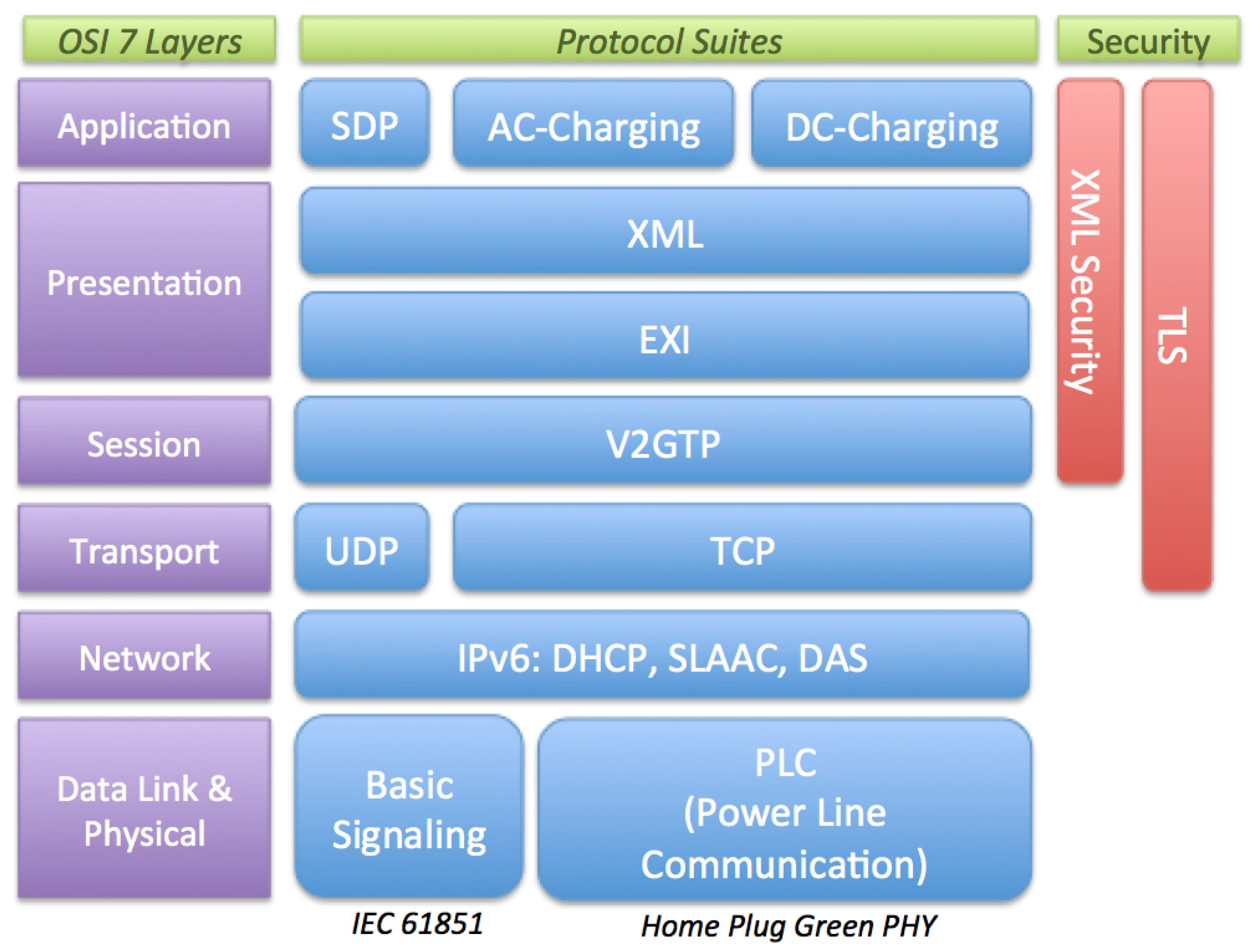
2.3. ISO/IEC 15118: High-Level Communication

At the heart of the EV charging mechanism is the ISO/IEC 15118 standard, and our test system mainly focuses on the conformance test to this standard. ISO/IEC 15118 defines its concepts and use cases in Part 1, communication details in Parts 2 and 3 and testing methods in Parts 4 and 5. ISO/IEC 15118 defines the communication details in all seven layers of OSI; physical and data-link layers are defined in Part 3, and all upper layers are defined in Part 2, as shown in Figure 2. Other parts of the standard are out of scope of this paper.
In the physical and data-link layer, Power Line Communication (PLC) is used. In particular, HPGP [11] standard is adopted for PLC, but other kinds of PLC technologies could be used if HPGP cannot be used in certain countries. For testing, ISO/IEC 15118 Part 5 only focuses on the pairing protocol of HPGP, called SLAC (Signal Level Attenuation Characterization). Our test system also follows this approach, and other parts of HPGP are out of the scope of this paper.
On top of PLC, IPv6 is used for the network layer, and UDP (User Datagram Protocol)/TCP (Transmission Control Protocol) is used for the transport layer. As these protocols are well implemented by off-the-shelf operating systems, such as Windows or Linux, to name a few, our testing system does not test these protocols explicitly, although the incorrect implementation of these layers will be indirectly detected by the test system.
For session management, ISO/IEC 15118 defines V2GTP (Vehicle-to-Grid Transfer Protocol), and all of the messages are delivered in V2GTP packets. The V2GTP protocol simply indicates the version of ISO/IEC 15118 in action and the packet type enclosed therein. The first packet type of the V2GTP packet is SDP (SECC Discovery Protocol). By this protocol, the EVCC broadcasts an SDP request packet and waits for a reply from an SECC. From the reply, EVCC learns about the IP address and the communication port of the SECC. The second packet type is the application message. Each application message is internally represented in XML (Extensible Markup Language) for maximum flexibility and portability, but the actual message in transit is encoded by the EXI (Efficient XML Interchange) algorithm for the compactness of the packet.
The communication of ISO/IEC 15118 is in the client-server model; for each application message type, the client, EV, sends a request message, and the server, EVSE, replies with a response message. By a series of request and response messages, the EV and EVSE exchange necessary information before, during and after charging. For example, for the session setup message type, EV sends the SessionSetupRequest message to EVSE and EVSE replies with the SessionSetupResponse message. The order of the application message types in the table roughly matches the actual communication order, but they are not necessarily the same.
For security, TLS (Transport Layer Security) helps EV to authenticate EVSE, protecting the confidentiality and integrity of the application messages. Additional protection of sensitive information is provided by XML security features. With XML encryption and signature features, EV can protect the confidentiality and authenticity of sensitive information, such as credit card numbers. The explicit test of theses functionalities is out of the scope of this work.

2.4. Home Plug Green PHY: Physical/Data-Link Layer

As the communication medium, ISO/IEC 15118 recommends Home Plug Green PHY. In particular, its pairing mechanism SLAC (Signal Level Attenuation Characterization) is a crucial step in EV-EVSE connection. EVSE measures and calculates the signal level from EV to find out which EV is connected with it through the charging plug, and our test system tests this procedure.
In SLAC, the EV first broadcasts the parameter exchange request message CM_SLAC_PARM.REQ, and the EVSE responds with CM_SLAC_PARM.CNF. Then, the EV broadcasts CM_START_ATTEN_CHAR.IND three times and CM_MNBC_SOUND.IND 10 times. The receiving EVSE measures the attenuation of the messages and reports back to the EV in the CM_ATTEN_CHAR.IND message. The EV then determines which EVSE to communicate with and sends CM_ATTEN_CHAR.RSP to the chosen EVSE. Finally, the EV requests logical network parameters of the EVSE in CM_SLAC_MATCH.REQ message, and the EVSE responds with CM_SLAC_MATCH.CNF.

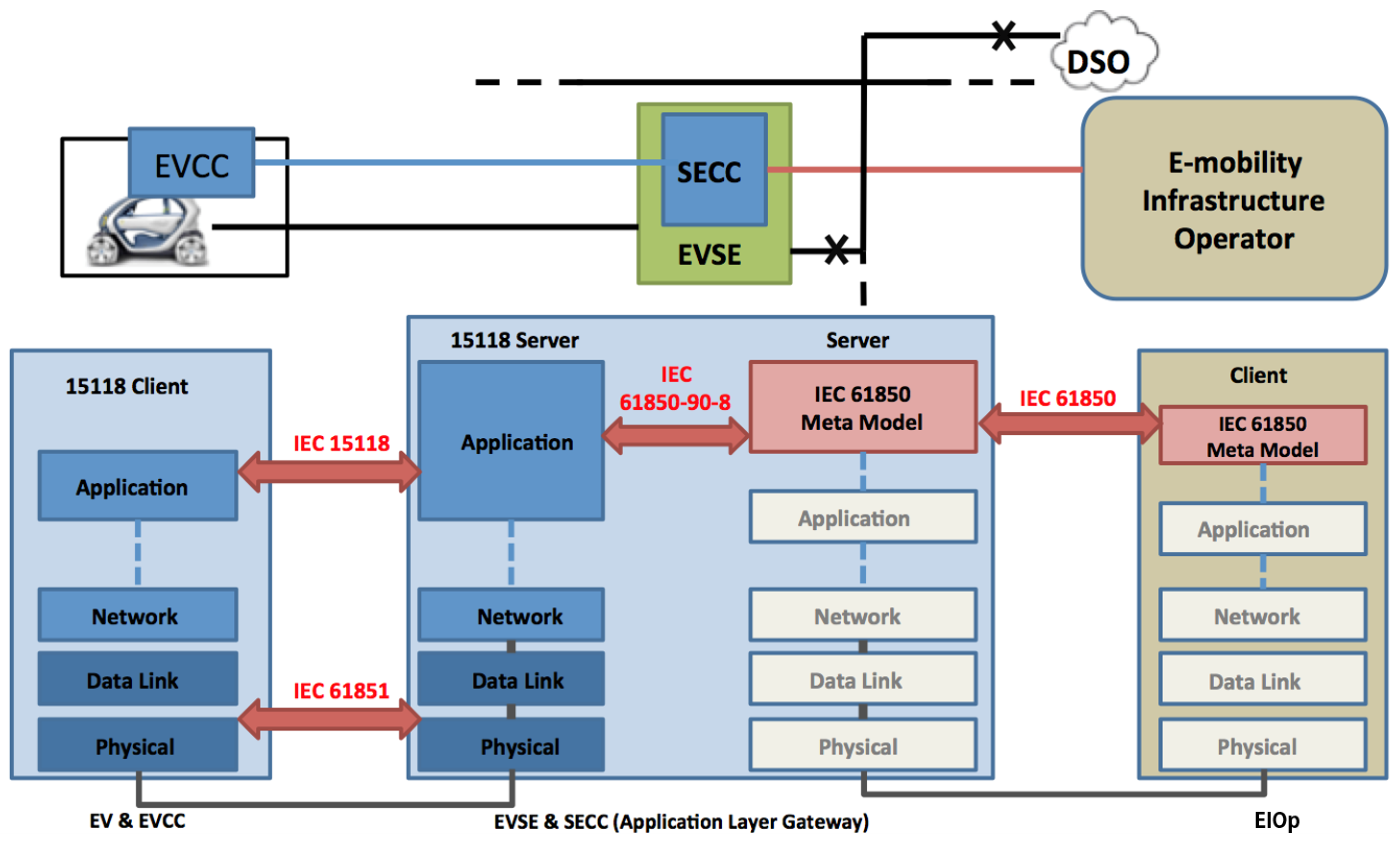
2.5. IEC 61850 and IEC 61850-90-8: Communication with the Operator

For the EV charging to be practical, the operator, a representative name of secondary actors, needs to get involved in user identification and authorization, billing and power control. Although there are protocols for management purposes between the operator and EVSE, such as CIM (Common Information Model) , OPC UA (Open Platform Communications Unified Architecture) and DMTF (Distributed Management Task Force) , we are mainly interested in the exchange of electric power-related values between them. In this regard, we assumed that all of the communication between EVSE and the operator is based on the IEC 61850 standard, as the EV and EV charger become part of the power grid from the operator’s point of view.
When EV and EVSE communicate by ISO/IEC 15118 and EVSE and the operator communicate by IEC 61850, there should be a bridging mechanism to transform 15118 messages to 61850 and vice versa. The transform work is done by converting the 15118 schema-based XML message to the 61850 schema-based XML message in the XSL (EXtensible Stylesheet Language) processor [24]. Although not complete, a technical report IEC 61850-90-8 defines such a transformation. We implemented this bridging mechanism in our reference EV charger, as shown in Figure 3. The bridging mechanism dynamically converts ISO/IEC 15118 messages to and from the IEC 61850 messages based on the corresponding XML schemas. Our test system assumes that the target EV charger implemented this feature if it claims to communicate with the operator.

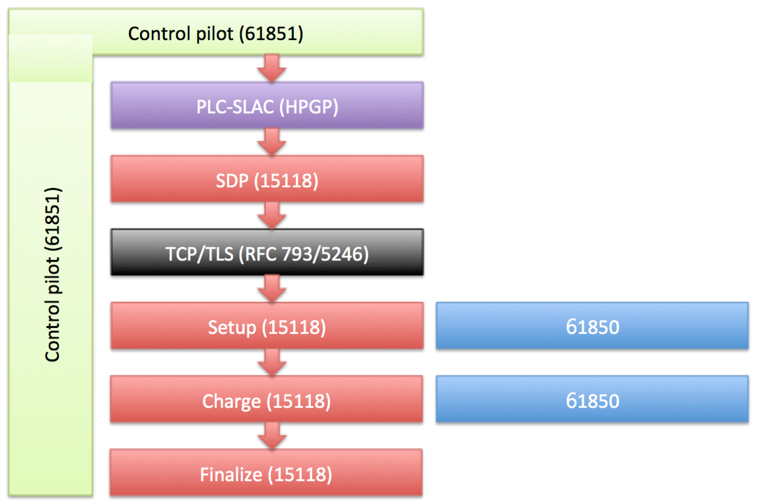
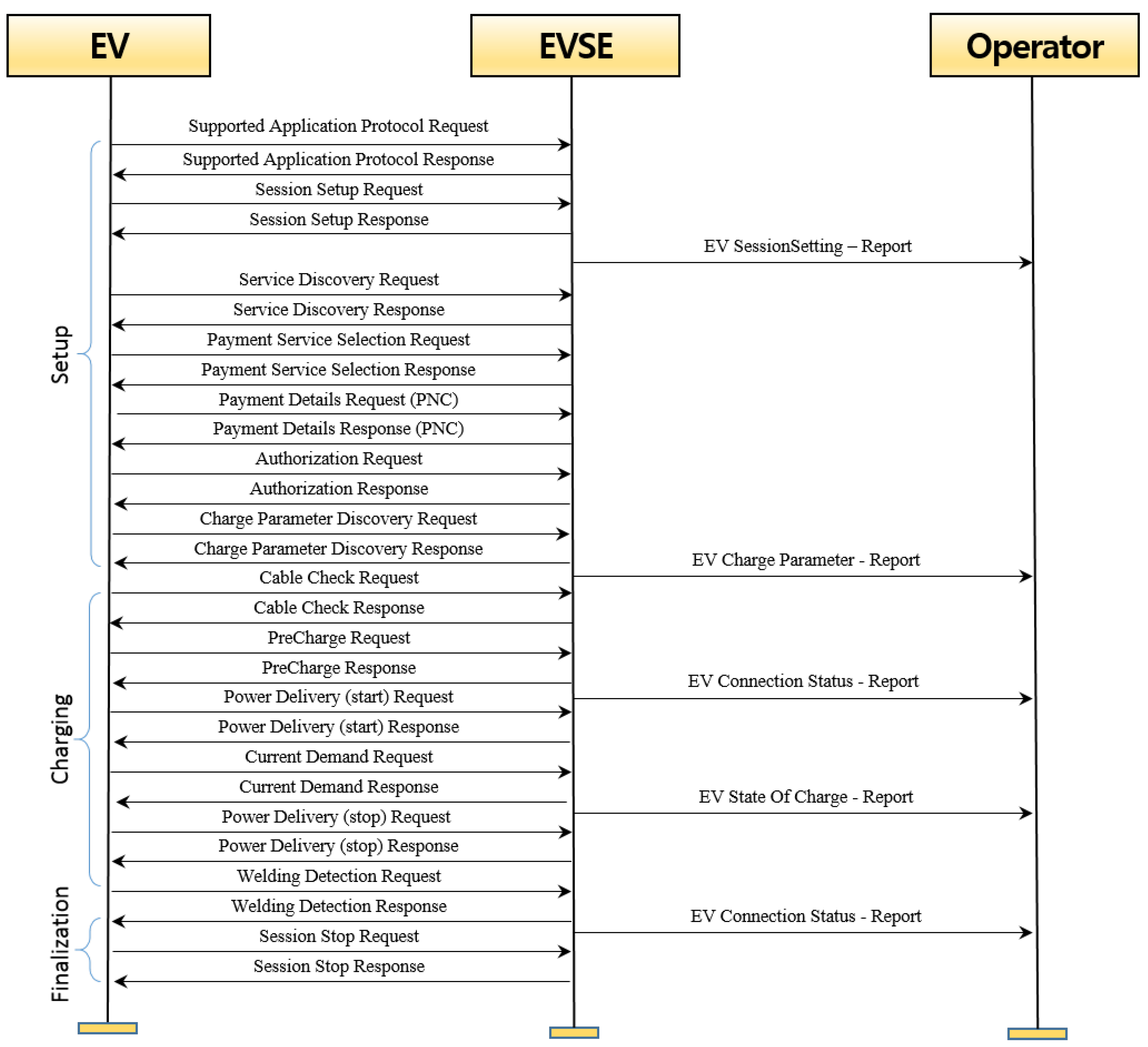
2.6. EV Charging Procedure

In this section, we describe the procedure of EV charging as defined in ISO/IEC 15118 and related standards. Our test system aims to verify if the target EVSE conforms to this procedure. For brevity, we focus on the DC (Direct Current) charging procedure. However, our test system can test AC (Alternating Current) chargers, as well.

Overview

Figure 4 describes the overall procedure of EV charging. Relevant standards are indicated in parentheses. When the user connects the charging cable: (i) the EV and EVSE detect the flow of current and start the control pilot protocol, as defined in IEC 61851. By the protocol, both parties can recognize different states throughout the charging procedure. Once EV and EVSE are ready: (ii) they initiate a PLC connection by the SLAC protocol as defined in HPGP. Once the PLC connection is established: (iii) the EV broadcasts an SDP packet onto the LAN (Local Area Network) to identify the IP address and port number of the EVSE. After receiving the information: (iv) the EV makes a TCP connection to the EVSE, secured by TLS.
At this point, the EV and EVSE can securely exchange TCP packets to control the charging procedure. We divided the procedure into three phases: Setup, Charging and Finalization. In the Setup phase, the EV and EVSE negotiate various parameters, including protocol version, user identity, service information, payment methods and charging parameters. In the Charging phase, they make an actual transfer of energy from the charger to the EV. During the transfer, they continuously exchange their status until the termination condition is met or an interruption is requested for any reason. In finalization, they perform safety checks before disconnection.
During the procedure, the EVSE reports to the operator regarding the charging session. The interaction between EVSE and the operator is not well defined yet in any standards. However, the technical report IEC 61850-90-8 describes the information model for data exchange between the EVSE and the operator. See Figure 5 for the detailed message sequence during the setup, charging and finalization phases.

3. Test System

We developed our EV charger test system using TTCN-3 (Testing and Test Control Notation Version 3) testing framework. In this section, we describe our testing methodology in detail.

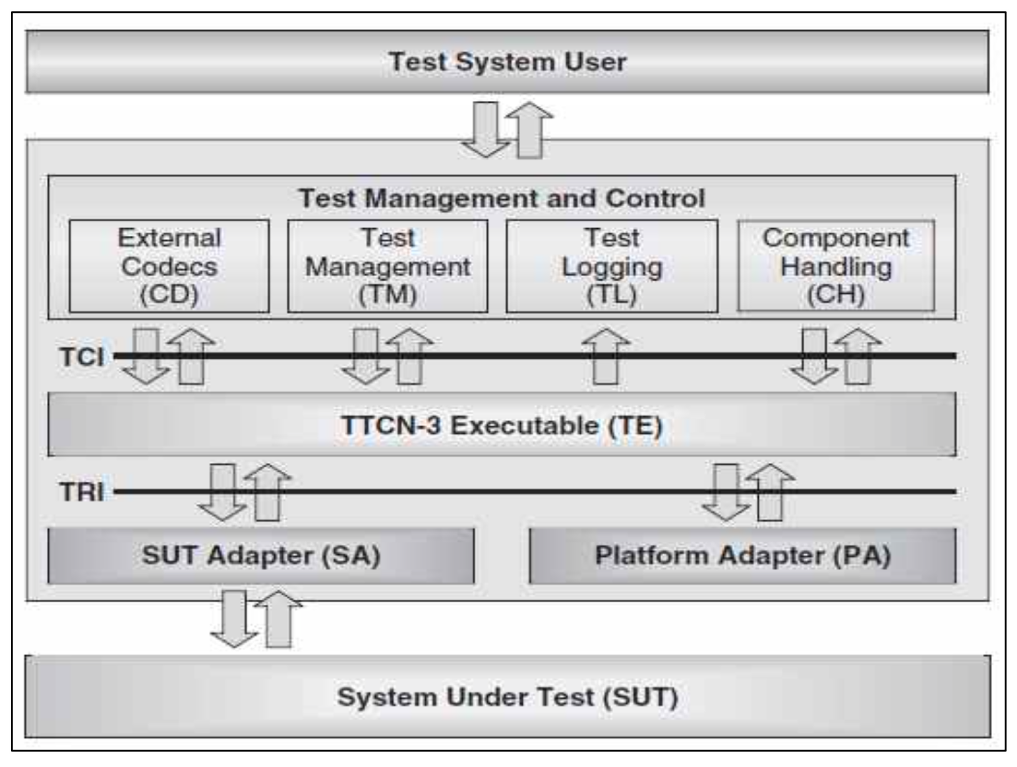
3.1. Test Language and Tools

TTCN-3 is a testing framework that has been used for testing many communication protocols for decades. It defines the TTCN-3 test scripting language, architecture of a test system and the interfaces between the components. Figure 6 depicts a typical TTCN-based test system architecture.
In a TTCN-3 framework, the TTCN-3 Executable (TE), compiled from a testing script written in TTCN-3 language, interacts with supporting components via TCI (Test Control Interface) or TRI (Test Runtime Interface) to control the testing procedure. The components above TCI in the figure are self-explanatory. Below, the Platform Adapterallows TE to utilize services from the operating system, such as the timer. The System Under Test (SUT) Adapter (SA) actually is involved in the message exchange between the test system and the SUT. The separation of testing logic (TE) and communication implementation (SA) makes the testing architecture flexible and extensible for various situations.
Most commercial and non-commercial TTCN-3 tools implement most components and interfaces of the testing framework. The user has to write a testing logic in TTCN-3 language. Although the tools support some SAs, most cases require the user to implement SA to customize the interaction with SUT for the specific communication technology. We used a commercial TTCN-3 tool, and we developed the SAs for Ethernet, PLC, 61850, the codec for EXI encoding C++, as well as the testing scripts in TTCN-3.

3.2. Testing Goals

Our test system aims to perform the conformance tests of a target EVSE against the following standards:
  • Conformance to ISO/IEC 15118 Part 2;
  • (Optional) Conformance to ISO/IEC 15118 Part 3, in particular, the SLAC protocol;
  • (Optional) Conformance to IEC 61851 basic signaling;
  • (Optional) Conformance to 61850-90-8 for interactions with the operator.
Some conformance tests are optional, as the target EVSE may not support all of the standards in the early stages of the EV charger development. We aim to build our test system flexibly to test EVSEs with different capabilities.
The reason why we only test SLAC for PLC is: (i) testing the full specification of the PLC modem is unnecessary; and (ii) SLAC is considered an important step in EV charging, because it ensures that the EV and EVSE is communicating with the right opponent. For testing IEC 61851 and PLC, we follow the recommended approach in ISO/IEC 15118 Parts 4 and 5.
Although evaluations were performed only for DC charging, our system supports AC charging, as well.

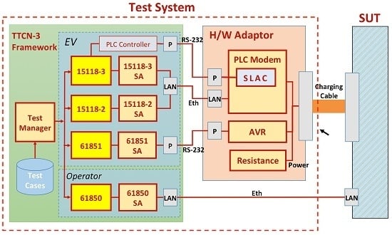
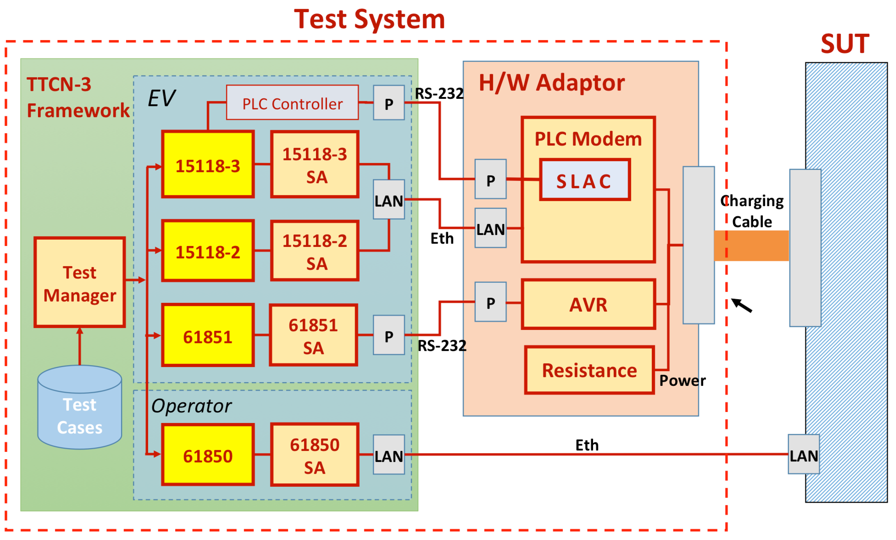
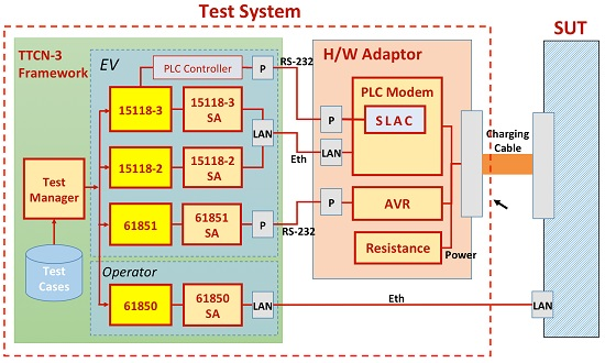
3.3. Test System Architecture

Our test system consists of a TTCN-3 framework [25] and a hardware adaptor (Figure 7). The TTCN-3 framework controls the testing logic. The test manager provides a user interface to choose a test scenario defined by the use case elements as in ISO/IEC 15118 Part 1. The test manager also allows the user to choose the capabilities of the SUT so that unnecessary software/hardware components are disabled accordingly. Once the test configuration is set, the test manager runs pre-determined test cases in order.
During a test, each module (yellow rectangles in Figure 7) plays independent roles simultaneously: Modules 15118-2 and 15118-3 perform the EVCC’s high-level communication and low-level communication, respectively; Module 61851 performs the basic signaling; and Module 61850 takes the operator’s role. Each module can be turned off depending on the testing scenario. The modules, which are unaware of the underlying communication protocols, can communicate with SUT because the SUT Adaptors (SAs) translate the high-level data from the modules to the actual communication protocol to SUT. For maximum flexibility in testing scenarios, the TTCN-3 framework provides only basic interfaces (Ethernet and serial ports), and the hardware adaptor supplements the full interface to the target EVSE.
The hardware adaptor consists of a PLC modem, AVR (Alf and Vegard’s RISC) microcontroller and a set of resistance. The PLC modem performs the SLAC protocol and converts the Ethernet packets from the framework to PLC packets and vice versa. The AVR component monitors the control pilot signal from the SUT and reports abnormal events to the testing framework through the serial connection. The resistance consumes the electricity during the charge to emulate a battery.
We separated the testing logic from the hardware interface for the flexibility of the test system. As the EVSE development is in its early stages in the industry, it is rare to find an EV charger with all of the features of PLC communication, control pilot, 15118 and 61850. Often, EVSE manufacturers are interested in testing only their implementation of high-level communication, setting aside low-level capabilities, such as PLC and actual energy transfer. In this case, the test system directly connects to the SUT over Ethernet, bypassing the hardware adaptor and disabling the 15118-3 and 61851 modules. Without the support of IEC 61850, we can also disable the 61850 module.

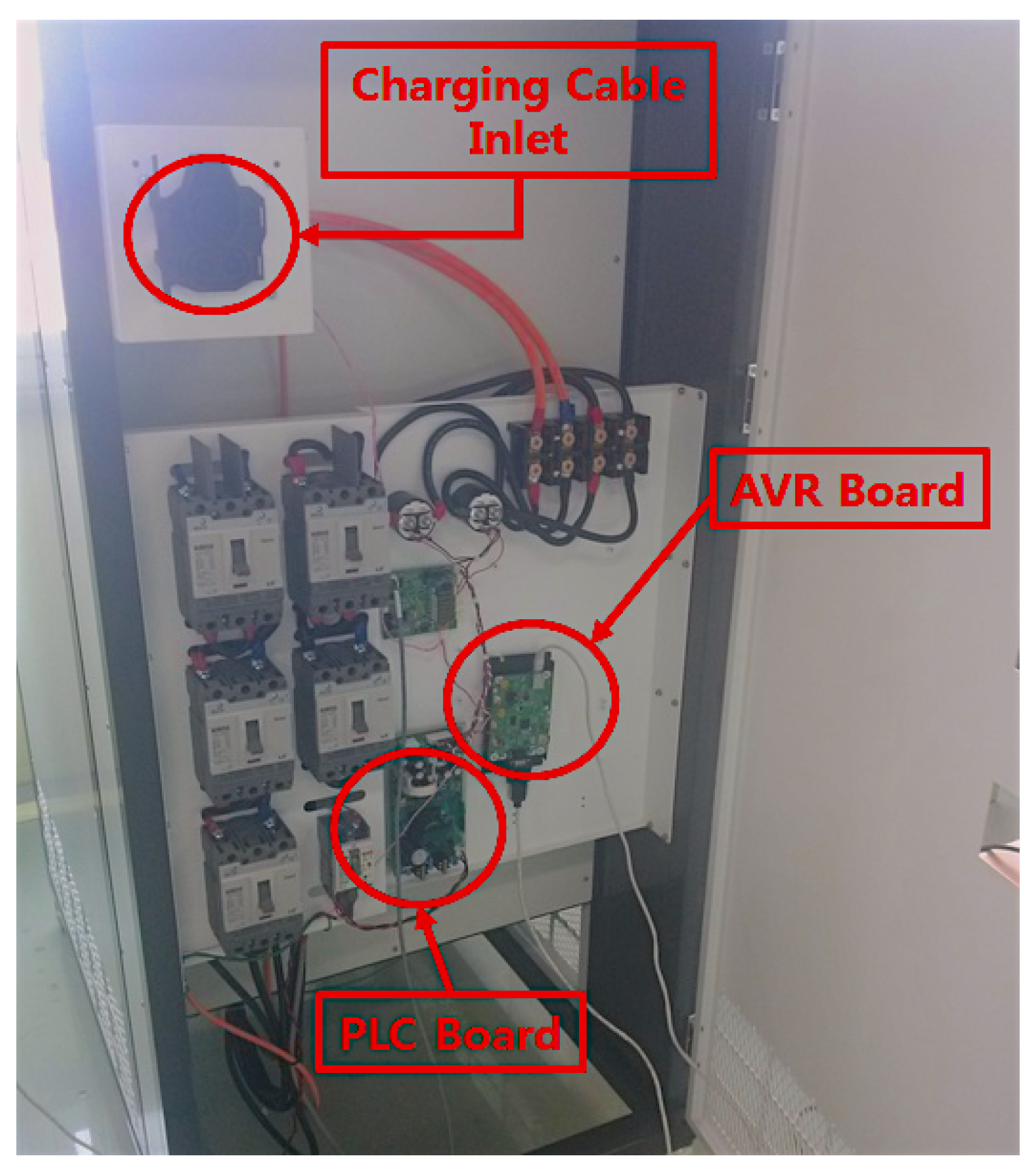
3.4. Test System Implementation

For the TTCN-3 framework, we used TestCast T3 Version 6.8.0.15, 2015 by Elvior (Tallinn, Estonia). On top of TestCast, we implemented the EXI codec, 15118-2 SUT adaptor, 15118-3 SUT adaptor, 61851 SUT adaptor and 61850 SUT adaptor. The 15118-3 SA implemented the SLAC protocol using the Winpcap library. The 15118-2 SA was implemented using XML support by TestCast, and the relevant EXI codec was implemented using a commercial library, Efficient XML by AgileDelta. For TLS connection in 15118-2 SA, we used an open-source library, GNUTLS (GNU Transport Layer Security) . The 61851 SA sends commands and receives reports to and from AVR through a serial connection. The 61850 SUT adaptor was implemented with IEC 61850 Version 2.02.00 DLL by SystemCorp (Perth, Australia, 2014). The TTCN-3 framework runs on a Windows 7 laptop computer (Samsung, Suwon, Korea) with CPU i5-4210U 1.7 2.4 GHz, RAM 4 GB and HDD 120 GB.
We built the hardware adaptor using Qualcomm Atheros QCA7000 IC (Qualcomm, San Diego, USA) for a PLC modem with a charging cable inlet of the SAE J1772 DC Extended Type (KET, Incheon, Korea). Figure 8 shows our implementation of the hardware adaptor.

4. Evaluation

In this section, we evaluate our test system. We first examine the coverage of test scenarios and test cases that our system supports. We then provide our lab test results against a reference EV charger that we built for evaluation purposes. Finally, we discuss the results of two testing events, the Chicago testival in 2014 and the Tokyo testival in 2015, where our test system was evaluated against EV chargers and EV testers from other vendors.

4.1. Test Case Coverage

A test case represents a single issue of conformance against one or more standard requirements. The ISO/IEC 15118 Part 4 (Committee Draft, CD version) presents 14 test cases for high-level communication and three test cases for basic signaling (IEC 61851), while Part 5 (CD version) presents five test cases for SLAC testing. Among the 17 test cases in Part 4, our test system covers 15 test cases, missing one for AC charging and one for renegotiation. In addition, we added four new test cases for high-level communication (including one negative test case) and seven new test cases for IEC 61850-90-8. For Part 5, we support only three test cases related to SLAC. In total, we support 29 test cases, three for basic signaling, 16 for high-level communication, seven for grid communication and three for the SLAC protocol. Table 1 summarizes the test case coverage of our test system.

4.2. Lab Testing Results

For evaluation purposes, we implemented two reference chargers. In this section, we report the implementation of reference chargers and testing results.

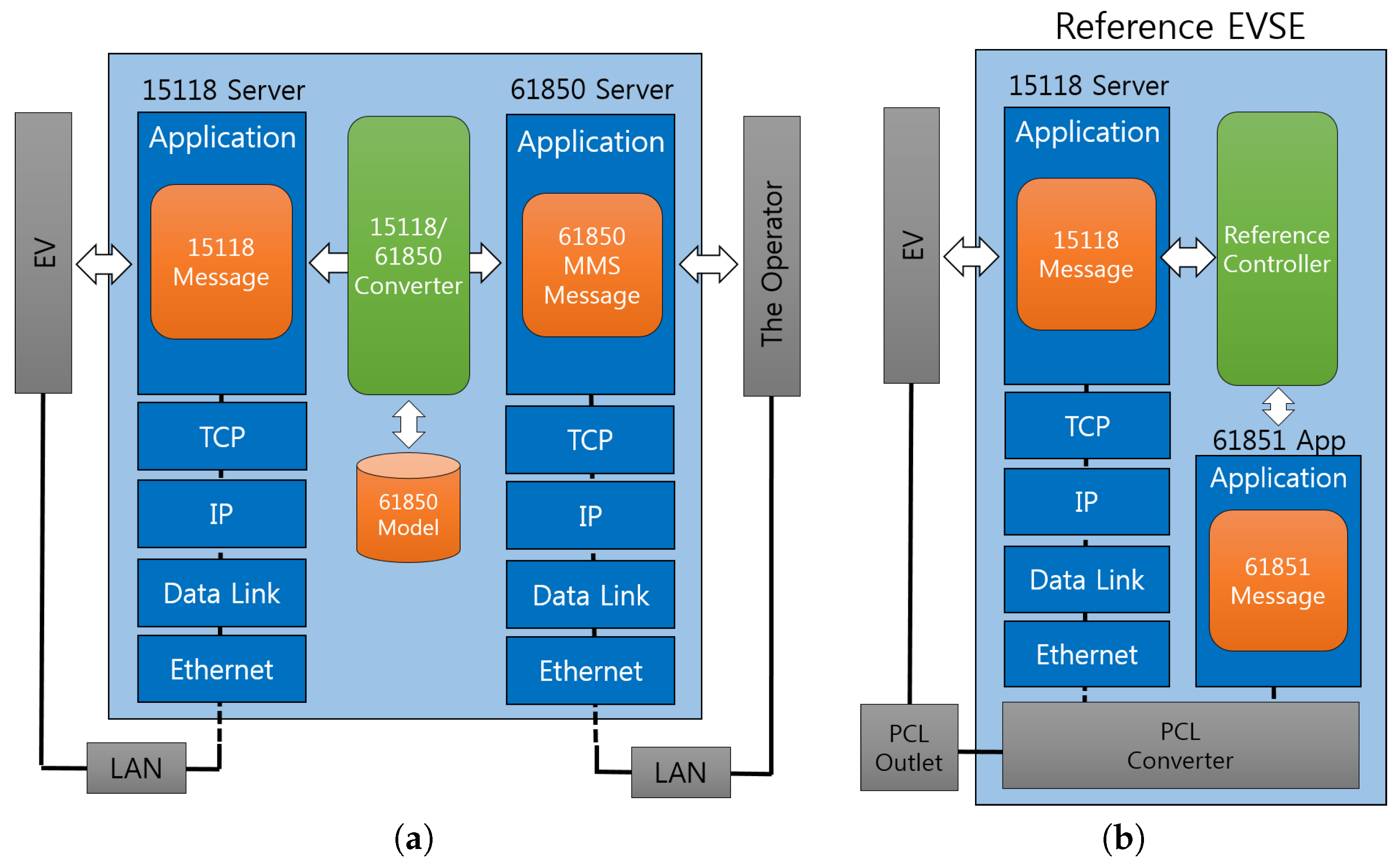
4.2.1. Reference Charger with High-Level Stack and IEC 61850

The first reference charger implements the high-level communication stack defined in 15118-2 and IEC 61850-90-8 to enable interactions with the grid operator and data mapping between 15118 and 61850 messages. Figure 9a illustrates the internal architecture of the reference charger with the 61850 capability.
To our best knowledge, this is the first reference charger that can interact with the operator using the IEC 61850 information model according to IEC 61850-90-8. This reference charger, however, lacks the IEC 61851 basic signaling and PLC communication stack. Instead, it connects with EV by Ethernet. While no real power transfer occurs, this reference charger can demonstrate how our testing system can perform conformance tests of high-level communication and the interactions with the operator.
The charger consists of the 15118 server, the 61850 server and a conversion engine between them. On the ISO/IEC 15118 side, the charger implements the SECC as defined in 15118 Part 2. On the IEC 61850 side, an IEC 61850 server is running in the charger. Between 15118 and 61850, there exists a 15118/61850 converter. This converter translates the IEC 15118 messages encoded in EXI to the IEC 61850-90-8 information model represented in MMS (Manufacturing Message Specification) messages, and vice versa.
The reference charger is developed in Windows 7 in C and C++, deployed in a laptop computer with CPU i5-4210U 1.7 2.4 GHz, RAM 4 GB and HDD 120 GB. The communication between 15118 and 61850 is implemented by shared memory. We based our implementation of the 15118 server on OpenV2G Version 0.9.2. We used PIS10 Stack Version 2 to implement the 61850 server.

4.2.2. Reference Charger with Full ISO/IEC 15118 Stack

The second reference charger implements the full stack of ISO/IEC 15118 Parts 2 and 3, including IEC 61851 basic signaling. This charger is a real DC charger that can deliver energy to an EV connected by a combo-type connector [23]. Using this reference charger, we can demonstrate how our testing system can test a charger that implements the full functions of the EV charger, except the capability of interacting with the operator.
This reference charger includes the 15118 server, the 61851 module and the reference controller (see Figure 9b). The reference controller controls the overall function of the EVSE by communicating with the 15118 server and the 61851 module. To communicate with the EV, the 15118 server and 61851 module communicate with the PLC converter, which transforms the data to control pilot and vice versa. The reference charger supports the combo-type coupler for the connection with the EV.

4.2.3. Results

In this section, we provide the test results against two independent reference chargers.
Against the reference charger with high-level stack and IEC 61850, we ran tests for PnC DC charging scenarios. The EV charger passed all of the test cases, including negative tests (see Table 2). The test system could properly take the role of EV and the operator simultaneously. We manually examined all of the communication between the EV and the EVSE and the EVSE and the operator, checked the timings of message deliveries and concluded that the test system properly tested the target EV charger.
Against the reference charger with the full ISO/IEC 15118 stack, we ran tests for EIM DC charging scenarios. The EV charger passed all of the test cases, including negative tests (see Table 3). The test system could perform the test cases for high-level communication and basic signaling simultaneously. We demonstrated out-of-range control pilot values and confirmed that the test system monitored the current condition in a timely manner. The SLAC test was also performed correctly. We manually examined all of the communication between EV and EVSE, checked the timings of message deliveries and concluded that the test system properly tested the target EV charger.

4.3. Testival Results

Lab testing has limitations. It may not cover all of the possibilities that can happen with the EV charging procedure. It may not work for different implementations of the target system from difference vendors. The test system itself may not pass the testing by other EV testing systems built by different test system vendors. In this section, we provide the testing results we obtained in two authorized international testing festivals (called testivals) where various EV manufacturers, EVSE manufacturers and test system vendors gather in one place and test their prototype systems with each other for interoperability tests. Due to non-disclosure-agreements (NDA), we suppress the details of the events, participants and test results.
Because of the size and weight of the test system for travel, we built a portable version of the hardware adaptor in a compact housing, without real power transfer, and a different connection type, as instructed by the testival.

4.3.1. 2014 Chicago Testival

The Chicago testival was held at Argonne National Laboratory in Lemont, IL, USA, from 13 to 14 November 2014. At this event, more than 20 companies and organizations participated. Our test system had opportunities to test against five EVSEs or testing systems. Below, we summarize the results in the testival (Table 4), but due to NDA, we suppress the counterpart’s information and the problem details.
When testing the SUT by Company A, the test system found three problems of the SUT: the SUT was using an old version of the SLAC protocol; SupportedAppProtocolRes was not received; and ChargeParameterDiscoveryRes was malformed. When testing with Company B, we found several problems in our test system: we found that the test system did not fill a necessary field in the CM_START_ATTEN_CHAR.IND message in SLAC; the test system was mistaken about the correct response code in the SessionSetupRes message and failed to send an application message. We fixed these problems at the site, and they never occurred afterwards. When testing with Company C, the SUT stopped working after the SDP response message because of some internal problem of the SUT. When testing Company E’s SUT, we found several defects of the SUT (see Table 4).

4.3.2. 2015 Tokyo Testival Event

The Tokyo testival was held at the Japan Automobile Research Institute (JARI) in Tokyo, Japan, from 15 to 17 April 2015. More than 10 companies and organizations participated in this event. Our test system tested seven other systems. Our test system at this event was an improved version of the system used at the Chicago testival.
The testing results are shown in Table 5. The test system found a defect of the SUT by Company A in the SLAC protocol. As in the Chicago testival, DIN-based SUTs (by Companies A, D, F) were not compatible after the SupportedAppProtocolRes message. The test system also found a timing problem of the SUT by Company C. The SUT systems by Companies B, E and G successfully passed all of the tests by our test system.

5. Conclusions

We built a conformance test system for the EV charger in accordance with the ISO/IEC 15118 standards, IEC 61851 and IEC 61850-90-8. The test system leveraged the TTCN-3 framework for its flexibility and productivity. To evaluate the system, we built two reference EV chargers: One that supports the communication with the operator with limited charging capabilities and one that is a full-fledged EV charger, but without interactions with the operator. We also participated in two international testival events for interoperability tests with other vendors. Our system evolved through these events, and at the end of the second testival, we confirmed that our test system is robust, efficient and practical.

Acknowledgments

This work was supported by the 2014 Research Fund of Myongji University.

Author Contributions

Minho Shin contributed to the research idea, design and implementation, as well as the evaluation of the system. Hwimin Kim contributed to the implementation and evaluation of the system. Hyoseop Kim contributed to the implementation, and Hyuksoo Jang supervised the research. All of the authors contributed to the writing of the paper.

Conflicts of Interest

The authors declare no conflict of interest.

References

  1. Gomez Vilchez, J.J.; Jochem, P.; Fichtner, W. The Impact of Electric Vehicles on the Global Oil Demand and CO2 Emissions; WCTR: Rio, Brazil, 2013. [Google Scholar]
  2. Falvo, M.; Sbordone, D.; Bayram, I.; Devetsikiotis, M. EV charging stations and modes: International standards. In Proceedings of the 2014 International Symposium on Power Electronics, Electrical Drives, Automation and Motion (SPEEDAM), Ischia, Italy, 18–20 June 2014; pp. 1134–1139.
  3. ISO technical committee. Road Vehicles–Vehicle to grid communication interface–Part 1: General information and use-case definition; ISO Technical Committee: Geneva, Switzerland, 2013. [Google Scholar]
  4. ISO technical committee. Road Vehicles–Vehicle to grid communication interface–Part 2: Network and application protocol requirements; ISO Technical Committees: Geneva, Switzerland, 2014. [Google Scholar]
  5. ISO technical committees. Road Vehicles–Vehicle to grid communication interface–Part 3: Physical and data link layer requirements; ISO Technical Committees: Geneva, Switzerland, 2015. [Google Scholar]
  6. International Electrotechnical Commission. Electric vehicle conductive charging system-Part 23: DC electric vehicle charging station; International Electrotechnical Commission: Geneva, Switzerland, 2014. [Google Scholar]
  7. International Electrotechnical Commission. Electric vehicle conductive charging system-Part 24 : Digital communication between a d.c. EV charging station and an electric vehicle for control of d.c. charging; International Electrotechnical Commission: Geneva, Switzerland, 2014. [Google Scholar]
  8. International Electrotechnical Commission. Communication networks and systems for power utility automation- Part 90-8: IEC 61850 object models for electric mobility; International Electrotechnical Commission: Geneva, Switzerland, 2014. [Google Scholar]
  9. CHAdeMO Association. Technical Specifications of Quick Charger for the Electric Vehicle: CHAdeMO 1.0.1; CHAdeMO Association: Tokyo, Japan, 2013. [Google Scholar]
  10. German Institute for Standardization. Electomobility-Digital Communication Between a d.c. EV Charging Station and an Electric Vehicle for Control of d.c. Charging in the Combined Charging System; German Institute for Standardization: Berlin, German, 2014. [Google Scholar]
  11. HomePlug Powerline Alliance, Inc. HomePlug Green PHY Specification Release Version 1.1.1.; HomePlug Alliance: Portland, OR, USA, 2013. [Google Scholar]
  12. Schmutzler, J.; Wietfeld, C. Analysis of Message Sequences and Encoding Efficiency for Electric Vehicle to Grid Interconnections. In Proceedings of the 2010 IEEE Vehicular Networking Conference (VNC) 2010, Jersey City, NJ, USA, 13–15 December 2010; pp. 118–125.
  13. Lewandowski, C.; Gröning, S.; Schmutzler, J.; Wietfeld, C. Performance evaluation of PLC over the IEC 61851 control pilot signal. In 5th Workshop on Power Line Communications; IEEE: Arnhem, The Netherlands, 2011. [Google Scholar]
  14. Käbisch, S.; Schmitt, A.; Winter, M.; Heuer, J. Interconnections and communications of electric vehicles and smart grids. In Proceedings of the 2010 First IEEE International Conference on Smart Grid Communications (SmartGridComm), Gaithersburg, MD, USA, 4–6 October 2010; pp. 161–166.
  15. ISO technical committee. Road Vehicles–Vehicle to grid communication interface–Part 4: Network and application protocol conformance test; ISO Technical Committee: Geneva, Switzerland, 2015. [Google Scholar]
  16. ISO Technical Committee. Road Vehicles–Vehicle to grid communication interface–Part 5: Physical layer and data link layer conformance test; ISO Technical Committee: Geneva, Switzerland, 2015. [Google Scholar]
  17. Groning, S.; Lewandowski, C.; Schmutzler, J.; Wietfeld, C. Interoperability testing based on TTCN-3 for V2G communication interfaces. In Proceedings of the 2012 International Conference on Connected Vehicles and Expo (ICCVE), Beijing, China, 12–16 December 2012; pp. 298–303.
  18. Hansch, K.; Pelzer, A.; Komarnicki, P.; Groning, S.; Schmutzler, J.; Wietfeld, C.; Heuer, J.; Muller, R. An ISO/IEC 15118 conformance testing system architecture. In Proceedings of the 2014 IEEE PES General Meeting/Conference Exposition, National Harbor, MD, USA, 27–31 July 2014; pp. 1–5.
  19. Kim, I.; Al-Hilo, A.; Jang, H.S.; Yoo, J.G. Conformance testing of SGSF-064-1 using CANoe. Korean Inst. Electr. Eng. 2015, 5, 1086–1101. [Google Scholar] [CrossRef]
  20. Kim, I.; Awan, T.W.; Abed, A.M.; Jang, H.S. Conformance testing of SGSF-064-1. Adv. Mater. Mech. Ind. Eng. 2014, 598, 704–708. [Google Scholar] [CrossRef]
  21. Awan, T.W.; Abed, A.M.; Kim, I.; Jang, H.S.; Shin, M. CAN based conformance testing using TTCN-3. Int. J. Comput. Commun. Eng. 2014, 3, 417–423. [Google Scholar] [CrossRef]
  22. ISO Technical Committee. Road vehicles-Controller area network(CAN); ISO Technical Committee: Geneva, Switzerland, 2015. [Google Scholar]
  23. SAE International. SAE Electric Vehicle and Plug in Hybrid Electric Vehicle Conductive Charge Coupler; SAE International: Warrendale, PA, USA; Troy, MI, USA, 2013. [Google Scholar]
  24. Ah, H.; Minho, S.; Intaek, K.; Hyuk-Soo, J. A study on communication controller of electric vehicle supply equipment for information exchange between electric vehicle and power grid. Korean Inst. Electr. Eng. 2014, 63, 1564–1570. [Google Scholar]
  25. European Telecommunications Standards Institute. Methods for Testing and Specification (MTS); The Testing and Test Control Notation Version 3; European Telecommunications Standards Institute: Sophia Antipolis, France, 2012. [Google Scholar]
Figure 1. Architecture and standards for the Electric Vehicle (EV) charging.
Applsci 06 00165 g001
Figure 2. The protocol stack of ISO/IEC 15118.
Applsci 06 00165 g002
Figure 3. Charging procedure overview with relevant standards in parenthesis.
Applsci 06 00165 g003
Figure 4. Charging procedure overview with relevant standards in parenthesis.
Applsci 06 00165 g004
Figure 5. Message sequence of EV charging.
Applsci 06 00165 g005
Figure 6. Testing and Test Control Notation (TTCN) testing framework.
Applsci 06 00165 g006
Figure 7. The architecture of the test system.
Applsci 06 00165 g007
Figure 8. Hardware adaptor of the test system.
Applsci 06 00165 g008
Figure 9. Architecture of the reference chargers. (a) Reference charger with high-level stack and IEC 61850; (b) Reference charger with full ISO/IEC 15118 stack.
Applsci 06 00165 g009
Table 1. Test case coverage. EVSE, EV Supply Equipment; HPGP, Home-Plug Green PHY; SLAC, Signal Level Attenuation Characterization.
CategoryOur Test SystemISO/IEC 15118 (Parts 4 and 5)
ISO/IEC 15118-2 DC1613
ISO/IEC 15118-2 AC01
IEC 61851 (Basic signaling)33
IEC 61850-90-8 (EVSE-Grid)70
HPGP SLAC35
Total2922
Table 2. Test result of the reference charger with high-level stack and IEC 61850. EVCC, EV Communication Controller.
No.Test caseBTargetProtocolVerdict
115118-TC1SECC Discovery Protocol (SDP)EVCCIEC/ISO15118Pass
215118-TC2Supported Application ProtocolEVCCIEC/ISO15118Pass
315118-TC3Session Setup MessageEVCCIEC/ISO15118Pass
415118-TC4Service DiscoveryEVCCIEC/ISO15118Pass
515118-TC5Payment Service SelectionEVCCIEC/ISO15118Pass
615118-TC6Payment DetailsEVCCIEC/ISO15118Pass
715118-TC7AuthorizationEVCCIEC/ISO15118Pass
815118-TC8Charge parameter DiscoveryEVCCIEC/ISO15118Pass
915118-TC9Cable CheckEVCCIEC/ISO15118Pass
1015118-TC10PreChargeEVCCIEC/ISO15118Pass
1115118-TC11Power Delivery (Start)EVCCIEC/ISO15118Pass
1215118-TC12Current DemandEVCCIEC/ISO15118Pass
1315118-TC13Power Delivery (Stop)EVCCIEC/ISO15118Pass
1415118-TC14Welding DetectionEVCCIEC/ISO15118Pass
1515118-TC15Session StopEVCCIEC/ISO15118Pass
1615118-NTC1Power Delivery (Negative)EVCCIEC/ISO15118Pass
1761850-TC1Connection CheckEVCCIEC 61850Pass
1861850-TC2TCP/IP Connection ReportEVCCIEC 61850Pass
1961850-TC3Session Setup CheckEVCCIEC 61850Pass
2061850-TC4Charge Parameter Discovery ReportEVCCIEC 61850Pass
2161850-TC5PreCharge ReportEVCCIEC 61850Pass
2261850-TC6Current Demand ReportEVCCIEC 61850Pass
2361850-TC7Welding Detection ReportEVCCIEC 61850Pass
Table 3. Test result of the reference charger with the full ISO/IEC 15118 stack.
No.Test caseContentsTargetProtocolVerdict
1SLAC-TC1Slack Parameter ExchangeEVCCHPGPPass
2SLAC-TC2Signal Strength MeasurementEVCCHPGPPass
2SLAC-TC3Logical Network Parameter ExchangeEVCCHPGPPass
461851-TC1Control Pilot Voltage RangeEVCCIEC 61851Pass
561851-TC2Control Pilot Frequency RangeEVCCIEC 61851Pass
661851-TC3Control Pilot Duty Cycle RangeEVCCIEC 61851Pass
715118-TC1SECC Discovery Protocol (SDP)EVCCIEC/ISO15118Pass
815118-TC2Supported Application ProtocolEVCCIEC/ISO15118Pass
915118-TC3Session Setup MessageEVCCIEC/ISO15118Pass
1015118-TC4Service DiscoveryEVCCIEC/ISO15118Pass
1115118-TC5Payment Service SelectionEVCCIEC/ISO15118Pass
1215118-TC6Payment DetailsEVCCIEC/ISO15118Pass
1315118-TC7AuthorizationEVCCIEC/ISO15118Pass
1415118-TC8Charge parameter DiscoveryEVCCIEC/ISO15118Pass
1515118-TC9Cable CheckEVCCIEC/ISO15118Pass
1615118-TC10PreChargeEVCCIEC/ISO15118Pass
1715118-TC11Power Delivery (Start)EVCCIEC/ISO15118Pass
1815118-TC12Current DemandEVCCIEC/ISO15118Pass
1915118-TC13Power Delivery (Stop)EVCCIEC/ISO15118Pass
2015118-TC14Welding DetectionEVCCIEC/ISO15118Pass
2115118-TC15Session StopEVCCIEC/ISO15118Pass
2215118-NTC1Power Delivery (Negative)EVCCIEC/ISO15118Pass
Table 4. Test results at the Chicago test event.
CounterpartScenarioResults
AISO/IEC 15118 DC chargingWrong SLAC version detected
SupportedAppProtocolRes not received
Wrong ChargeParameterDiscoveryRes was received
BISO/IEC 15118 DC chargingTester sent a wrong SLAC message
Tester’s incorrect behavior detected during SessionSetup
Tester’s incorrect behavior detected during CableCheck
CISO/IEC 15118 DC chargingFailed after SDP
DDIN70121 DC chargingFailed after SupportedAppProtocolRes
EISO/IEC 15118 DC chargingUnknown error occurred during SLAC
SDP response was not received
Authorization response was not received
Table 5. Test results at the Tokyo test event.
CounterpartScenarioResults
ADIN 70121 DC chargingWrong SLAC message was received
Failed after SupportedAppProtocolRes
BISO/IEC 15118 DC chargingSuccess
CISO/IEC 15118 DC chargingSLAC timing problem detected
DDIN 70121 DC chargingFailed after SupportedAppProtocolRes
EISO/IEC 15118 DC chargingSuccess
FDIN 70121 DC chargingFailed after SupportedAppProtocolRes
GISO/IEC 15118 DC chargingSuccess

